
Abstract
On the verge of the 50th anniversary of Vander Lugt's formulation for pattern matching based on matched filtering and optical correlation, we acknowledge the very intense research activity developed in the field of correlation-based pattern recognition during this period of time. The paper reviews some domains that appeared as emerging fields in the last years of the 20th century and have been developed later on in the 21st century. Such is the case of three-dimensional (3D) object recognition, biometric pattern matching, optical security and hybrid optical–digital processors. 3D object recognition is a challenging case of multidimensional image recognition because of its implications in the recognition of real-world objects independent of their perspective. Biometric recognition is essentially pattern recognition for which the personal identification is based on the authentication of a specific physiological characteristic possessed by the subject (e.g. fingerprint, face, iris, retina, and multifactor combinations). Biometric recognition often appears combined with encryption–decryption processes to secure information. The optical implementations of correlation-based pattern recognition processes still rely on the 4f-correlator, the joint transform correlator, or some of their variants. But the many applications developed in the field have been pushing the systems for a continuous improvement of their architectures and algorithms, thus leading towards merged optical–digital solutions.
Export citation and abstract BibTeX RIS
1. Introduction
In the forthcoming years we are going to celebrate the fiftieth anniversary of the Vander Lugt's formulation for pattern matching based on matched filtering and optical correlation. The paper was submitted on 31 May 1963 and was published in April 1964 [1]. According to Vander Lugt's seminal work, the presence of a given object of interest (soon after, referred to as the reference pattern or target) can be automatically detected, located and identified in a scene by using a filter with the complex conjugated Fourier transform of the object in a optical processor that performs the correlation between the two images, namely, the scene and the reference. Optical correlation thus becomes the operational principle on which pattern matching is based: the output correlation intensity is taken as a metric that refers the similarity between two images. Real-time pattern recognition broke through quickly as one of the most promising applications of optical processing. Two basic architectures were proposed to implement optical correlation, namely, the 4f-correlator, so called since the distance between the input and the output plane is four times the focal length of two similar lenses [2], and the joint transform correlator (JTC) [3], where the reference and the scene are placed side by side in the input plane of a single lens Fourier transformer. These two architectures to produce optical correlation have been intensively analysed and compared [4] for decades and, with many variants, are still widely used today. Referring to digital methods in computer vision, correlation is also a common and extensively used operation utilized in low-level vision tasks to localize and identify patterns in scenes. Correlation is the dot product of two images (when they are suitably normalized and considered as vectors), so it represents the angle between them and can be properly taken as a measure of their similarity [5].
In the frame of this paper, it is not possible to list and describe all the lines of research developed in the domain. A large number of books, special sections and review papers in scientific journals and conferences report on the different approaches, research and applications developed in the field of correlation-based pattern recognition during this period of time (e.g. [6–26]). There exists the scientific society for Pattern Recognition and seven indexed journals with the topic 'pattern recognition' in their titles in the subject category of Computer Science and Pattern Recognition of the SCImago Journal Rank of 2011 (e.g. Pattern Recognition since 1968, Pattern Recognition Letters since 1982). Conferences named 'Optical Pattern Recognition', 'Automatic Target Recognition', and 'Signal Processing, Sensor Fusion, and Target Recognition'—all of them organized by the International Society on Optical Engineering (SPIE)—go beyond their twentieth edition in 2012. Overall, it can be said that the progress in pattern recognition is broad, deep and intense. The research activity takes place not only within the optics community, but it also involves many other disciplines. It does not just concern the process segment, but also the related areas of systems and devices that make many of the new processes feasible and meaningful. The continuous progress of computers in terms of performance, power, and flexibility and, at the same time, reduced cost, is remarkable. So is the technological maturity of spatial light modulators (SLMs) and cameras, the development of photosensitive materials for massive optical storage, among other important components and sub-systems of current hybrid optical–digital correlators used for pattern matching.
In the following, we will mainly focus on some relevant aspects of the research developed in the 21st century, and we apologize for some important advances that may be missing. We review some domains that appeared as emerging fields in the last years of the 20th century and have been intensively developed since then. Such is the case of three-dimensional (3D) object recognition, which is a challenging case of multidimensional image recognition because its implications in the recognition of real-world objects independent of their perspective. Time-variant information and colour content add more dimensions and, hence, complexities to 3D object recognition. In pattern matching, the success of detecting and identifying the correct object strongly depends on the object information provided to and processed by the recognition system. A way to improve the accuracy of the pattern matching processes may involve the introduction of additional information about the target to be detected, such as colour or depth. On the other hand, to avoid useless complications derived from an excessive amount of information, one must carefully choose the most distinctive piece of information that precisely describes the target and makes it different from other possible objects in the scene. Thus, depending on the application, depth can be either crucial and distinctive, or just irrelevant. The principles and evolution of three-dimensional (3D) object correlation and recognition are reviewed in section 2.
Biometric recognition is essentially pattern recognition for which the personal identification is based on the authentication of a specific physiological characteristic that is possessed by the subject. Traditionally fingerprints, and later on the face, iris and retina, have been used to define a person's identity. But a biometric recognition process based solely on a single biometric signal or factor is often insufficient to meet the requirements for a secure and complete identification. Multifactor systems integrate several single signals for a more reliable recognition of a person. Quite often, security applications involve the use of encryption–decryption techniques that can be implemented by optical processors. Biometric recognition often appears combined with encryption–decryption processes. The use of correlation techniques in biometric verification and optical security is surveyed in section 3.
The architectures designed for the processors so far described mostly correspond to the well-known 4f-correlator, or the JTC, or some of their variants. In fact, many applications of correlation-based pattern matching need continuously improved systems, architectures and algorithms that produce merged optical–digital solutions, some of which are described in section 4. Finally, section 5 outlines the conclusions of this analysis in the context of the research done so far in the 21st century. It aims to contribute to the celebration of the 50th anniversary of Vander Lugt's formulation of matched spatial filtering and optical correlation for signal detection.
2. Three-dimensional (3D) object correlation and recognition
Traditionally, most of the correlation techniques for pattern recognition have dealt with two-dimensional (2D) objects or images. The natural extension to 3D objects, which reflects real-world needs, has motivated the development of new correlation techniques for 3D pattern recognition. Given rotation, scale variation, colour, and change in the illumination of the object soon arose as serious difficulties to overcome in early 2D pattern recognition algorithms, these problems have appeared again in 3D pattern recognition and become yet more complicated because of the third dimension.
In general, a 3D object is represented by a function located in the spatial coordinate system. The recognition of this object with respect to a reference involves storing the information contained in both the reference and the object 3D functions, and scanning over six degrees of freedom (three axes for translation and three more axes for rotation) to achieve the best match. To simplify the problem, many proposed algorithms rely on processing a set of planar images generated from 2D projections of the 3D scene. Since optical correlation, particularly the correlation performed by the JTC architecture, has proved to be a powerful tool in 2D pattern recognition, it has been extended to 3D problems through a variety of ingenious algorithms. Although most of them are inspired by the performance of the optical processors, they also require digital computation in some extent. The overall process of 3D pattern matching can be divided into three main stages: optical image acquisition, digital computation, and correlation. Very often, there is no clear distinction between the second and third stages and, thus, correlation can be found in the last part of digital processing.
In this section we review the optical–digital correlation methods for 3D pattern recognition and, in some representative cases, we provide detailed descriptions of their fundamentals. The methods are classified into five main categories: methods based on multiple viewpoint projections, methods based on digital holography, methods based on Fourier transform profilometry, methods based on range images, and polychromatic 3D pattern recognition. Such a large number and variety of approaches reveals, on the one hand, the importance of the issue and the great efforts devoted to investigating it, and on the other hand, the non-existence of a single route to solve the problem, but rather a multiplicity of possibilities usually defined by the application.
2.1. Methods based on multiple viewpoint projections
Rosen proposed a method [27–30] based on an optically inspired scheme for 3D Fourier transforming and correlating a set of 2D perspectives of the reference and the scene. This collection of 2D projections of the 3D scene can be recorded in different ways: for instance, either by lateral shift of the camera (parallel observation [29]), or by rotating the camera around the origin point of the scene space (converging observation [29]). In parallel observation, the multiple viewpoint projections are acquired by shifting the camera mechanically, so that the camera captures a single perspective projection at each position. This method was employed the earliest and is briefly described here. It is relatively simple because it does not require any special capturing hardware or algorithms. However, two main drawbacks have been reported. One drawback is the need for a camera with a wide field of view and good field aberration compensation in the extreme points of view. The second drawback is that the acquisition process becomes a slow mechanical scan procedure. The first drawback can be overcome by using the converging observation as an alternative configuration. Thus, for different locations of the camera, the captured image plane is orthogonal to the line that connects the origin point of the 3D scene space and the camera sensor plane. In such a case, the field angle is independent of the lateral shift, and therefore, the field of view requirements are limited to the scene width. The second drawback can be overcome by positioning a number of cameras in an array (top part of figure 1), however the entire camera array is then generally too expensive. Instead, as we will describe later, a method inspired in integral imaging [31] uses a microlens array combined with a common lens that allows the simultaneous acquisition of a large number of multiple viewpoint projections in a single camera shot (figure 2(a)).
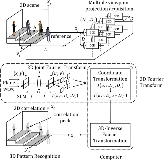
Figure 1. Schematic diagram of the correlation based process for 3D object recognition. It consists of optical 3D Fourier transforming and correlating a set of 2D perspectives of the reference and the scene. The collection of multiple 2D viewpoint projections of the 3D scene is recorded by means of an array of cameras.
Download figure:
Standard image
Figure 2. Principle of integral imaging to capture multiple 2D viewpoint projections of a 3D scene. (a) General scheme, (b) definition of distances, (c) generation of sub-images from the elementary images.
Download figure:
Standard imageLet us review the mathematical concept of 3D JTC with parallel observation for 3D pattern recognition as it was proposed by Rosen in [27, 28] and as depicted in figure 1. Camera coordinates (Dm,Dn) are defined as Di = iD in figure 1. The Fourier transform of a 3D input function t(xs,ys,zs) for a given location (Dm,Dn) of the camera is given by
where λ is the wavelength of the plane wave, (u,v) are the transverse coordinates of the spatial frequency domain, and f is the focal length of the lens l used for Fourier transforming the scene (central part of figure 1). Using geometrical considerations from figure 1, the coordinates (x,y) of the 2D projections displayed on the SLM can be written in terms of the spatial coordinates of the 3D scene (xs,ys,zs). Assuming a small depth of the input scene in comparison with the observation distance L, some straightforward approximation [27] can be applied to obtain the expressions
where M is the image magnification factor at the SLM plane and L is the distance between the camera plane and the front plane of the scene (xs,ys,0) (figure 1). Substituting equations (2) into (1) yields
Equation (3) represents a 3D Fourier transform, multiplied by a linear phase function, which transforms a scene function t(xs,ys,zs) into a 3D spatial frequency function T(wx,wy,wz), where wx = Mu/λf,wy = Mv/λf, and wz = M(Dmu + Dnv)/λfL. It can be remarked that wz depends on the transverse spatial frequency variables u and v, which is rather unusual. The Fourier transform contained in equation (3) (without the linear phase function) satisfies the convolution theorem [2] and, therefore, it can be used in the spatial correlation process. As for the limitations of the system, if we assume that Dmax represents the maximum size of the camera array in both the xs and ys directions and B represents the maximum transverse frequency also in both directions (i.e., umax = vmax = B), then the condition DmaxB ≥ λfL/Mδzs must be satisfied in order not to lose the information on the smallest input element of longitudinal size δzs.
The 3D input function t(xs,ys,zs) contains a reference r(xs,ys,zs) at the origin and a scene (generally consisting of a single object or a few objects) represented by function o(xs,ys,zs) located around another point (a,b,c) (top part of figure 1). Therefore, the 3D input function is

Taking this into consideration, the concept of the JTC can be thus adopted into the new 3D correlator. Applying the 3D Fourier transform to the input function of equation (4), the intensity distribution of the joint power spectrum in the focal plane of the lens l (central part of figure 1) is
where R and O are the 3D Fourier transform defined by equation (3) of r and o, respectively. The intensity I(u,v,Dm,Dn) is recorded and sent to the computer for a simple coordinate transform to obtain  . After an inverse 3D Fourier transform of
  , the output result is
where symbols ⊗ and ∗ represent the correlation and the convolution, respectively, and δ(⋅) is the Dirac delta function. Equation (6) is reminiscent of the result obtained with a classical 2D JTC. Thus, the first two terms of the autocorrelation in equation (6), which are not relevant, are centred at the origin, whereas the third and the fourth terms, which contain the cross correlations between the reference and the scene, appear centred at the points (a,b,c) and (−a, − b, − c), respectively. If at least one of the distances (a,b,c) is longer than the respective size of the tested scene o, then the cross-correlation does not overlap and is spatially separated from the central irrelevant terms and can thus be detected. An intense correlation peak reveals the presence of an object in the scene that is similar to the reference at a given location in the 3D space (bottom part of figure 1).
This 3D pattern recognition method shows shift invariance in the entire 3D space, but it is sensitive to geometrical distortions, including rotation. To overcome the latter problem, a computer-generated complex function that replaces the reference was proposed in [30]. Although it made the implementation more complicated, positive experimental results were obtained by increasing the computational burden in a 3D hybrid optical–digital correlator.
Although the conventional JTC algorithm has proved to be a powerful tool for matching and tracking applications in the area of 2D pattern recognition, it has some drawbacks as well. For instance, JTC produces a low-correlation peak intensity with broad peak width and low peak-to-sidelobe ratio that may affect the target detection and location process [9, 11]. For JTC performance improvement, several techniques have been proposed. Among them, it is worth mentioning the fringe-adapted JTC [32], which has been extended to 3D pattern recognition [33]. According to this technique, the joint power spectrum of equation (5) is multiplied by a real valued filter, called the fringe-adjusted (FA) filter, which is defined as

where B(u,v,Dm,Dn) and A(u,v,Dm,Dn) are either constants or functions. B(u,v,Dm,Dn) is used to control the gain, and A(u,v,Dm,Dn) is used to eliminate the pole problem that would otherwise be associated with an inverse filter. The FA joint power spectrum is obtained by multiplying the FA filter of equation (7) with equation (5). When |R(u,v,Dm,Dn)|2 ≫ A(u,v,Dm,Dn), B(u,v,Dm,Dn) = 1, and r(xs,ys,zs) = o(xs − a,ys − b,zs − c), then the FA joint power spectrum can be rewritten as
The rest of the process applied before to the joint power spectrum of equation (5) would be now applied to IFA(u,v,Dm,Dn) of equation (8), that is, a coordinate transformation to obtain  and an inverse 3D Fourier transform. As a result, the correlation output would be
It can be observed that the correlation peak distribution for the case r(xs,ys,zs) = o(xs − a,ys − b,zs − c) is no longer a set of broad peaks but, instead, in equation (9) it becomes a set of Dirac delta functions.
The correlation output can be further enhanced by using the Fourier-plane image subtraction technique [34, 35]. With this technique, the reference power spectrum and the tested scene power spectrum are subtracted from the joint power spectrum before inverse Fourier transforming. This subtraction removes the zero order and the correlation terms corresponding to the intraclass associations of similar tested objects, thus reducing false alarms while enhancing the correlation output. As a result of combining 3D JTC with FA filtering and Fourier-plane subtraction, the recognition of 3D objects improves, not only in a more accurate location, but also in other performance metrics such as the correlation peak intensity, the peak-to-correlation energy, the peak-to-sidelobe ratio, and the peak-to-clutter ratio [33].
As mentioned earlier, the multiple viewpoint projections can be advantageously acquired in a single shot by using a microlens array attached to the camera (figure 2(a)). With this technique, called integral imaging [31], a large number of elementary images of a 3D scene are obtained by the microlens array and can be recorded by a camera. Integral imaging has been combined with classical 2D correlation in [36] and used for 3D object recognition. The processor can be implemented all-optically, but it lacks precision in the longitudinal segmentation of 3D objects. In a different approach, integral imaging is used to reconstruct the 3D objects of the scene as a prior step to computing the 3D correlation [37]. Several assumptions have to be made on the microlens imaging performance. First, the depth of focus of the microlenses and the spatial 3D configuration of the scene allow one to assume that the images of all the objects are obtained in the same plane P (approximately the focal plane), independently of their location in the scene. Second, the elementary images generated by neighbouring microlenses do not overlap. Third, the second imaging step, performed by the camera lens onto the CCD sensor, does not introduce any distortion. With these assumptions, all the calculations for retrieving the depth information of the imaged 3D objects can be conducted by considering plane P. Figure 2(b) illustrates the imaging principle of the microlens array. The coordinate xp of an object point projected onto plane P by microlens number p depends on both the scene lateral coordinate xs and the distance from the object point z (depth). From the geometry of figure 2(b), (pΦ − xs)/z = (xp − pΦ)/d, which yields

where Φ is the microlens diameter and d the image distance (in general, d can be approximated by the microlens focal length). The distance between two projections of the same object point given by two microlenses p and q is

Thus, from equation (11), it is possible to recover the depth of an object point z by comparing the projections through different microlenses. Although, in principle from equation (11), two elementary images would suffice to retrieve the depth z of every object point, the use of several views allows a more accurate identification of the features and hence, a more precise calculation of depth. This multiple identification of the object points is possible by taking into account the multiple viewpoint projections imaged by the microlens array. In fact, a particular feature has to appear at regular locations in the various elementary images. All these considerations have been taken into the design of a stereo-matching algorithm to determine the depth of every object point of the 3D scene [37, 38]. From the reconstructed depth value z of each particular object point and from the values of its projected lateral coordinates (x0,y0) in the central elementary image, the lateral scene coordinates (xs,ys) of such object point can be computed using equation (10), thus giving (xs,ys) =− [z/d](x0,y0). These equations allow the reconstruction of the 3D object shape (xs,ys,z) independently of its distance from the microlens array and, therefore, this 3D scene can be used to compute the 3D correlation. A direct 3D correlation between a reconstructed reference r(xs,ys,z) and a reconstructed tested object o(xs,ys,z), calculated in intensity units, gives a measurement of their true similarity in all three spatial coordinates, with full shift invariance in every direction. The correlation intensity can be computed in the Fourier domain, from the expression |r⊗o|2 = |FT−1(RO*)|2. To further improve the discrimination capability of the recognition system, a strong nonlinearity within the frame of the kth-law nonlinear correlation [39] can be used instead of ordinary correlation.
The location of the correlation peak reveals the location of an object identical to the reference object in the 3D scene. An advantage of using integral imaging for 3D pattern recognition is that it provides real reconstructed volumes that are 3D models of the input scenes. However, the process necessary to recover the 3D information from the integral images can be complicated for complex scenes [40]. The recognition system is capable of finding a 3D shift of the reference object in the scene, but not rotations. This problem can be overcome by using a sub-image array [41]. A schematic diagram of the digital transformation of the captured elementary images in sub-image arrays is shown in figure 2(c). The pixels at the same location in all the elementary images, or equivalently, at the same angular position with respect to the optic axis of the microlenses, are collected to form the corresponding sub-image [42]. The sub-image has two useful properties that can be exploited to carry out the 3D correlation. First, each sub-image represents a specific angle in which an object is observed regardless of its position in the 3D scene. In other words, the perspective of an object contained in a given sub-image does not change as the object shifts in the 3D scene. The angle invariance of the sub-image makes it possible to select a certain angle of observation deterministically regardless of the object position. Second, the perspective size is invariant independently of the scene depth. If an object moves closer to or farther from the microlens array, its perspective size in a given sub-image is constant, only its position changes. This size-invariant property overcomes the need for a scale invariant detection technique, even though the tested object shifts in the longitudinal (depth, z) direction. Using these two properties of the sub-image, the presence of the reference object can be detected even if it appears 3D shifted and out-of-plane rotated in the scene [41].
Photon-counting three-dimensional (3D) passive sensing and object recognition using integral imaging [43] have been applied to automatic target recognition (ATR). Photon-counting images generate distributions with far fewer photons than conventional imaging. Photon events are modelled with a Poisson distribution. A microlens array generates photon-limited multi-view (elementary) images to discriminate unknown 3D objects. In general, the nonlinear correlation of photon-limited images provides better performance than the linear matched filter. Photon-counting imaging, optical correlation and pattern recognition are also applied to improve security in information authentication, as will be described later in section 3.2.
2.2. Methods based on digital holography
Holography has been applied to 3D pattern recognition because a hologram is a record of the 3D information of an object. In this field, Poon and Kim [44] proposed a 3D acousto-electro-optical recognition system that used heterodyne scanning interferometry to separately record the single holograms of a reference and a tested object. Optical recognition of 3D objects was achieved by 2D correlation of holographic information from the reference and the tested object. This is possible because holograms have all the 3D object information in the form of a 2D fringe pattern. Initially, the system was not fully 3D shift invariant; more specifically, it was not invariant to the shift of the tested object along the depth axis (z axis). This problem was overcome by using FA filtering and Wigner analysis [45]. Subsequently, the correlation between the phase-only information of the respective holograms of the 3D reference and tested objects, through the Wigner analysis, allowed them to determine the 3D location of any matched 3D object [46].
In digital holography, a digital camera is used as the recording medium that allows immediate image acquisition and digital processing of the holograms. A method for 3D pattern recognition based on phase-shifting interferometry, digital holography and correlation has been proposed in [47–49]. The optical system for the digital holographic recording step is based on a Mach–Zehnder interferometer, as depicted in figure 3(a). A linear polarized laser beam is split into two beams. One of them illuminates the object and the other one forms an interference pattern together with the light diffracted by the object onto the CCD sensor of a camera. By using phase-shifting interferometry, four interference patterns between the diffraction field generated by the object o(xs,ys,zs) and the reference beam are recorded. The phase of the reference parallel beam is shifted using a combination of phase retardation plates that introduce four different phase values αp = {α1,...,α4} = {0, − π/2, − π, − 3π/2} during the recording process (four-step method). The reference beam at the recording plane can be written as B(x,y;αp) = Abexp{j(φb + αp)}, where Ab and φb are arbitrary constants of the amplitude and phase, respectively. The amplitude distribution due to the object beam at the detector, Ho(x,y), within the Fresnel approximation and neglecting secondary diffraction, can be evaluated from the superposition integral
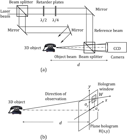
Figure 3. (a) Phase-shifting interferometer for recording a digital hologram of a 3D object. (b) Relation between the displacement of the hologram window and the angle of view.
Download figure:
Standard imageThe intensity of the interference pattern recorded by the device is then given by
From this equation, the complex field Ho(x,y) at the detector plane can be obtained by combining the four intensity patterns resulting from the interference of the object beam with the reference beam with its phase shifted by the aforementioned αp values. Thus, apart from constant values, the amplitude and phase of Ho(x,y) can be computed using the expressions
As in conventional holography, different regions of the digital hologram record different perspectives of the 3D object, which can be reconstructed by numerical propagation of Ho(x,y). The discrete amplitude distribution in the window W of the hologram used for reconstruction  is modified by a linear phase factor that takes into account the direction of observation (figure 3(b)). Assuming that the hologram window W is defined by the rectangle function rect(m,n) of the discrete spatial coordinates (m,n) in the detector plane, that (ax,ay) are the pixel coordinates of the window function, and that (Wx,Wy) denote the transverse size,
  can be written as
The discrete complex amplitude distribution at any plane in the object beam, within the paraxial approximation and with the limitations imposed by the sensor size, can be calculated, apart from constant factors, by the discrete Fresnel transform of  or, alternatively, by using the propagation transfer function method
where FT denotes Fourier transform, (u,v) are discrete spatial frequencies, (ms,ns) correspond to the object plane coordinates, Nx and Ny are the number of samples in the x and y directions, (Δxs,Δys) is the spatial resolution at the object plane, and d is the distance between the front object plane and the detector plane (hologram) [47].
The correlation step for 3D object recognition uses a Fourier-matched filter approach that is applied to the information obtained by digital holography. Let us consider a 3D reference object r(xs,ys,zs) also located at a distance d from the camera, and its corresponding Fresnel hologram Hr(x,y). The correlation between different views of the 3D tested object with a given perspective of the reference object can be evaluated by extracting partial windows from Ho(x,y) at different positions in the hologram, followed by reconstructing the tested object at a distance d and computing the correlation with the reconstruction of the reference. The correlation intensity of one perspective of the reference  with one perspective of the tested object
  , generated from the holograms, is
From equation (17), it can be seen that by correlating different regions of the two digital holograms, properly modified by a linear phase factor, the correlation between different perspectives of the 3D reference and tested objects is determined and, therefore, the possibility of 3D pattern matching is evaluated. It is to be noted, however, that the correlation of equation (17) is not shift invariant under axial displacements (z axis). Moreover, rough objects involve fast fluctuations of the reconstructed phase for lateral translations, thus affecting the transversal shift invariance. It is possible to modify the described technique to achieve 3D recognition with extended 3D shift invariance [48, 49]. Once the holograms have been obtained, the amplitude and phase of the complex wavefronts generated by the 3D objects are calculated in a set of planes parallel to the detector plane within the Fresnel approximation. In this way, the diffraction volume of the object scene is reconstructed. This procedure allows one to apply the 3D correlation to the diffraction volume generated by the objects. Because of the coherent light used for the hologram recording, a speckle pattern is unavoidably generated and this noise affects the reconstruction. Some improvement can be achieved by discarding the phase of the complex field and by using the irradiance distribution in the reconstruction plane. It is also possible to reproduce the complex amplitude in planes tilted with respect to the detector plane by using displaced windows in the digital hologram that are illuminated with tilted plane waves. This is equivalent to comparing different perspectives of the objects, thus allowing the recognition of the reference object with small rotations, typically less than 1°. It is possible to make the 3D recognition more tolerant to distortions caused by rotation and changes in scale by using a composite filter [10]. With this composite filter the rotation tolerance obtained is limited to a few degrees. To generalize the recognition of the object to any arbitrary rotation and, in addition, to classify the out-of-plane orientation of the object, a bank of composite filters and a two-layer neural network have been used in [50]. Several lossless and lossy data compression techniques have been applied to digital holograms created by phase-shift interferometry. The results in 3D object reconstruction and recognition have been presented and evaluated in [51]. Compression permits a more efficient storage of digital holograms. In order to be useful for a real-time 3D object recognition system, the compression strategy requires efficient algorithms that make it advantageous to spend time compressing and decompressing rather than transmitting the original data. In an interesting overview paper [52], Javidi and co-workers compared the use of integral imaging and phase-shift digital holography for 3D object recognition and presented the relative advantages and drawbacks of each method.
It is possible to eliminate most of the limitations of the laser-based holographic recording stage by using holographic techniques for incoherently illuminated scenes. Thus, multiple viewpoint projection holograms are digital holograms generated from the acquisition of multiple projections of a 3D scene from various viewpoints. As has been detailed in section 2.1, a shifting digital camera, or alternatively, an array of imaging elements, can perform this recording stage on a 2D grid basis. Multiple viewpoint projection holograms are synthesized by spatial correlation between the incoherently illuminated 3D scene and a point spread function (PSF). Different PSFs generate different types of holograms [53]. Among them, the digital incoherent modified Fresnel hologram is generated by directly correlating the multiple viewpoint projections of the 3D scene with a PSF of a quadratic phase function [53–55]. All the multiple viewpoint projections are processed with the same quadratic PSF. In contrast to conventional imaging systems, in the reconstructed hologram there appears a constant magnification of objects despite their axial position in the 3D scene. This anomalous behaviour concerning scale, which can be explained from the parallax effect, needs to be compensated in normal image reconstruction. However, it has been advantageously exploited in 3D pattern recognition [56]. With this hologram, one requires just a single 2D filter to detect all objects identical to the reference in the 3D scene, independently of their distance from the camera. This is a relevant improvement compared to other holographic and non-holographic 3D recognition methods, in which a number of filters are required to recognize identical objects that are located at different axial distances from the camera. As mentioned earlier, a similar axial distance independence on the image scale has been already proved by a 3D object pattern recognition method that works with sub-image arrays [41].
2.3. Methods based on Fourier transform profilometry
Fourier transform profilometry is a powerful technique for the automatic measurement of 3D object shapes [57]. It is based on projecting a fringe pattern onto an object surface and capturing the image by camera. The image looks like a distorted fringe pattern that conveys the information about the object shape and depth. For a proper application of the method, only objects with smooth surfaces can be considered, so that the spatial frequency on the object, with regard to both reflectivity and the 3D surface, is small in comparison with the frequency of the projected fringes. The distorted pattern is digitally analysed through its Fourier series expansion. It has been shown that the object height information is encoded in the phase of the first order. This principle has been used in [58] to compare the 3D shape of an object with a reference in a modified JTC setup for optical recognition purposes. In the first stage, the distorted fringe patterns of both the reference and the tested object are displayed side by side at the input plane of the JTC. In the Fourier plane, the joint power spectrum is filtered and only the first order is captured. In the second stage, this image is sent to the SLM placed at the input plane of the JTC, which produces the desired 3D correlation at the output plane. It is worth mentioning that this method achieves the correlation between the phase-encoded 3D input objects and not that between the fringe patterns themselves. The recognition method is invariant to transverse and axial shifts, but is sensitive to rotations and other distortions of the object. With this method, there is no need for electronic or digital processing of the initial patterns, the JTC only requires simple equipment and the whole optical system can operate at nearly video rates. To achieve rotation invariance, this technique has been combined with circular harmonic decomposition in [59]. Some improvement in the correlation performance can yet been achieved by replacing the first Fourier transformation of the JTC by a fractional Fourier transformation [60]. With this architecture of joint fractional transform correlator, narrower and sharper correlation peaks, higher peak intensities and improved discrimination capability can be obtained for 3D object recognition.
2.4. Methods based on range images
In comparison with the 2D approach, 3D pattern matching methods show, in general, an increase in the computation burden that cannot be always alleviated by optical implementation. Recognition tolerant to rotations in the object is still a challenge. Most attempts to achieve it add severe limitations to the problem or very heavy calculation. However, it is worth commenting on the success obtained by some proposals, particularly those oriented to a specific application, such as the correlation based on range images. A range image of a 3D object in the spatial coordinates (x,y,z) is defined as z = f(x,y), where z is the distance from a reference plane to the object (figures 4(a) and (b)). The correlation of range images has been used to evaluate the shape conformity of a tested object with respect to a reference object [61]. The Fourier transform of a phase-encoded range image can be denoted by

where ω is a scaling factor. To illustrate its properties [62] let us consider a 3D object as a set of elemental polygons or facets. A facet fc(x,y) is defined as a plane p(x,y) = ax + by + c bounded by a support function s(x,y) that is a constant different from zero only in the region of support, so that


Figure 4. (a) 3D object (pyramid) and definition of coordinates; (b) range image of the pyramid (a); (c) PhFT intensity in rectangular coordinates of the spatial frequency domain; (d) PhFT intensity in angular coordinates of the spatial frequency domain.
Download figure:
Standard imageThe phase-encoded facet is exp[jωp(x,y)]s(x,y) because the outside area of the region of support is empty. The Fourier transform of a phase-encoded facet becomes

where α, β are constants and γ is a phase factor. The PhFT of a facet has the following properties (figure 4(c)):
- It provides orientation-to-position mapping. Planes with different orientations are represented by Dirac delta functions with different positions in the space-frequency domain. Thus, when a plane rotates in the space domain, it produces a translation in the PhFT domain.
- It maps a facet into a peak. The orientation, area and boundary of the facet determine the position, amplitude and distribution of the peak, respectively. A change in the scale of the facet produces a change in the intensity of the peak, but its position does not change.
- Its intensity is invariant to arbitrary translations of the object in the (x,y) plane as well as along the view line (z axis) [63]. This shift invariance is an essential property for a 3D pattern matching operation based on the correlation between the intensities of the PhFTs.
Since a complex 3D surface can be approximated by a set of polygons, its PhFT image consists of clusters of discrete peaks, which has been called the constellation signature of the surface [62]. Phase-only correlation of the PhFT intensity has been used for 3D face recognition under limited in-plane and out-of-plane rotations in [62].
A more general approach is described in [63, 64], where the authors propose a method for recognition of 3D objects with an arbitrary rotation in the space. The method is based on the definition and calculation of a complete signature for the object, called the 3D object orientation map (3DOOM). Provided the full 3D information of the object is known, its PhFT intensity for any possible orientation can be computed. A map—the 3DOOM—that contains the information from all viewpoints is then built by placing and pasting on a spherical image the PhFTs expressed in spherical coordinates. Obviously, to cover a full angular range the model object needs to have been scanned in all possible directions, so that any single facet faces the view line for at least one direction. Alternatively, the view line scans the space while the object is fixed. Once the sphere of the 3DOOM is computed, the recognition of a 3D object at an arbitrary rotation consists on matching the PhFT intensity for this direction with the 3DOOM. To this end, a correlation on a unit radius sphere between two functions expressed in spherical coordinates, namely the PhFT intensity of the rotated tested object and the 3DOOM of the reference object, is performed for pattern matching. When the range image of an object is scaled, its PhFT is multiplied by a constant factor and, consequently, a global change in intensity is produced. Small errors in mapping the 3DOOM caused by the digitalization process applied after the change of scale can be neglected in a first approach. A method for intensity invariant pattern recognition based on correlation [65] has been additionally introduced in the algorithm. In another context, this method has been applied to 3D shading to achieve a correlation-based detection under arbitrary lighting conditions [66]. Successful results of both scale- and full range rotation-invariant 3D object recognition are presented in [67, 68]. These methods are effective for 3D pattern detection. However, they involve heavy computational burden and digital implementation.
2.5. Polychromatic 3D pattern recognition
So far through section 2, we have seen that 3D correlation can be used to enhance the discrimination capability by introducing a third dimension, i.e. depth. A great number of papers on 3D pattern recognition have been published, but most of them only consider greyscale objects. To obtain a more complete colour 3D pattern matching, some techniques that combine 3D correlation and multichannel processing of the spectral information have been proposed and implemented.
In multichannel correlation, the red–green–blue (RGB) components coming from the trichromatic decomposition of the image acquired by a camera are usually processed and the correlation results obtained in each of these channels are combined by means of some arithmetic or logical operator to identify and locate the desired colour object. However, a RGB correlation-based system heavily relies on the intensity of the colour reference or target. This fact can be a problem when the reference is a coloured object in the presence of dissimilar colour objects with higher intensity. In such a case, the cross-correlation peak can be higher than the autocorrelation peak in some or even all channels, thus producing a false alarm. This and other problems in the multichannel correlation of colour objects has been successfully overcome by applying coordinate transformations to the RGB values, e.g. into the opponent colour channels (named ATD from A-achromatic luminance, T-tritan, D-deutan) of human vision models [69] or into the CIELAB colour space (L*a*b* as defined in the CIE 1976 standard) [70].
Let us mention here some colour 3D pattern recognition techniques, the monochrome version of which has been already presented earlier. The FA joint transform correlation (equations (7)–(9)) has been extended to deal with plain colour objects, firstly in 2D [71] and later in 3D pattern recognition [72]. The technique proposed in the second paper [72] involves a coordinate transformation from RGB values into CIELAB colour space to reduce false alarms and to improve the discrimination capability of the recognition system. In [73], a FA joint transform correlation-based technique has been proposed for detecting very small targets involving only a few pixels in hyperspectral imagery. Fourier transform profilometry has been extended to recognize 3D colour objects by decomposing the 2D deformed fringe pattern, which carries all the 3D information, in a set of chromatic channels, which convey the colour information of the object [74]. A variety of chromatic systems (RGB, ATD, CIELAB) can be used for object decomposition to obtain 3D colour pattern recognition with fine adjustment of the system properties.
3D colour correlation has also been proposed to recognize 2D colour objects [75, 76]. The colour distribution of polychromatic objects is introduced as a third dimension in addition to the 2D spatial variables. The technique can be optically implemented by encoding the 3D functions in 2D signals, either by interlacing the channels of the colour images [77] or by putting them side by side [78].
3. Correlation in biometric verification and optical security
3.1. Biometric pattern matching
Biometric verification covers a set of reliable methods for personal identification and plays an important role in forensic and civilian applications. Face pictures, fingerprints, iris images and eye fundus images are examples of biometric images. Biometric verification refers to a pattern matching process by which the live biometric input from an individual is compared with the stored biometric template of that individual. Optical filtering and correlation have proved to be very useful in biometric recognition since the early stages of the technique. Correlation provides match metrics, such as the peak-to-correlation energy, the peak-to-sidelobe ratio, and the peak-to-clutter ratio [9, 79], that can be used to define the cost function for the verification process. An input biometric is verified as belonging to a certain individual if the corresponding cost function has a value lower than a given threshold. The minimum value of the cost function allows one to find the closest match and, hence, to identify individuals.
In biometric recognition, the images of interest are often characterized by some specific details or minutiae, which involve localized high-frequency features (e.g. iris or fingerprints). Methods that act exclusively in the image domain may not be the most convenient solution to the problem of effective discrimination of one class from another. On the other hand, the input biometric is bound to show some differences from the reference biometric because of common variations such as rotations, scale changes, perspective, and partial occlusion that should have no or little effect on the final recognition result. In such cases, composite correlation filters can be designed based on a set of multiple training images [10, 80]. Accurate image matching in the presence of image variability is essential for biometric authentication. The performance of advanced correlation filters for face, fingerprint, and iris biometric verification is investigated in [81]. This study shows that advanced filters, such as synthetic discriminant function filters [82], offer very good matching performance in the presence of variability in biometric images (i.e. facial expression, illumination change, distortion, in-plane rotation, noise, etc).
In the case of fingerprints, direct global correlation of rolled inked fingerprints has a significant failure rate caused by the plastic deformation of fingerprints when rolling. Wilson et al describe a method to overcome the problem in [83]. The two fingerprints being compared are firstly rotationally and translationally aligned about their cores and, secondly, partitioned into tiles. The data contained within the tiles are then compared by correlation. Combining optical features extracted from these local correlations with neural networks for classification and matching can yield fingerprint recognition even for fingerprints that have too low image quality to be matched using minutia-based methods. They test their optical and neural network fingerprint matching system on 200 000 image pairs and obtain accuracy over 90%. In [84] fingerprint images are firstly enhanced using a supervised filtering technique that incorporates a recurrent neural network and, secondly, a FA joint transform correlation algorithm is used for pattern matching [32]. In a different approach, Hennings et al [85] take advantage of the good properties of wavelets for a joint localization in the space and frequency domains. Unlike the traditional correlation filter design that is applied to the image intensity of a pattern class, they propose to design a correlation filter for each leaf in the best wavelet packet admissible tree that they can find for a given class. Despite the computational cost of the wavelet packet decompositions, this method offers the flexibility to find more suitable spaces for correlation filter classification. It turns to be advantageous in fingerprint recognition, thus suggesting that fingerprint images have some features that remain more consistent in the underlying wavelet subspaces than in the spatial domain.
Among other biometrics, the human face is the most familiar element; it has the highest social acceptability and is less subject to psychological resistance as means of security control. Much effort has been made to develop methods for automatic recognition of the human face. However, the 3D nature of the face, the high variability and the inherent complexity in the natural facial expressions make this challenging task a subject for multivariant recognition of the same object (intraclass face patterns). Two different approaches have been reported concerning 2D and 3D information, respectively. Taking advantage of optical broad-bandwidth and spatial parallelism of optical analogue computing, a massive quantity of 2D images can be processed instantly and in parallel using optical correlators. Javidi et al described a nonlinear JTC-based two-layer neural network that used a supervised learning algorithm for face recognition [86]. The reported performance of several seconds per face would have been better if modern optical components and electronic devices had been used. In this line, a significant improvement was obtained by extending the single-channel JTC to a compact multi-beam multichannel parallel JTC [87] with a zone plate array as the Fourier transformer. Each zone plate of the array acts as a Fourier transform lens for an independent channel, thus producing an array of joint power spectra of individual joint pairs without lateral overlapping. A significant improvement can be also obtained using a volume holographic correlator where an input object can be compared simultaneously with all the stored patterns. The simple introduction of a static diffuser near the object plane to modulate the object pattern with a high-frequency speckle pattern (speckle modulation) effectively enhances the performance of the volume holographic correlator [88]. The autocorrelation Dirac delta function of the speckle field modifies the output correlation pattern, making the correlation peak sharp and bright, and suppressing the sidelobes. In addition, the angular interval can be small to enlarge the capacity of correlators. This method has been satisfactorily used in human face recognition [88]. An alternative approach considers the three-dimensionality of a face in the correlation operation. The human face can be expressed as a set of facets and, as has been described in section 2.4, the phase Fourier transform (PhFT) of the range image of a face provides a signature of that face [62]. To achieve partial invariance to in-plane rotations, the circular harmonic transform [89, 90] was used in the design of a new version of the reference. Finally, correlation is established between the PhFT of the input and such version of the reference [62].
3.2. Secure verification of encrypted information
The great progress in optoelectronic devices has made optical technologies attractive for information security. Optical security techniques involve tasks such as encoding, encryption, decryption, recognition, secure identification, use of biometric images and optical keys. The security strength of optical cryptography comes from the ability of optics to process the information in a hyperspace of states, where variables such as amplitude, phase, polarization, wavelength, spatial position, and fractional spatial frequency domain, can all be used to serve as keys for data encryption or to hide the signal [91]. Optical processors and, more specifically, optical correlators have been extensively used to secure information because of their inherent parallelism, high processing speed and their resistance to intruders. Following complex information processes, a signal (image) is first hidden from human perception to keep it secret; second, the hidden signal is extremely difficult to replicate with the same properties to avoid counterfeiting; and third, the signal is automatically, real-time, and robustly retrieved in compact processors by authorized users.
In a seminal paper [92], Refrégier and Javidi proposed an optical method, the double random phase encryption (DRPE), to encode a primary image f(x) into a complex valued encrypted function ψ(x) of white-noise-like appearance that does not reveal its content. The method uses two random phase key codes on each of the input and Fourier planes, represented by random functions n(x) and m(u) uniformly distributed on [0, 1]. The coordinates x and u correspond to the spatial and frequency domains, respectively, in our simplified one-dimensional notation. In the first stage (encryption), a random phase mask (RPM), named RPM-I and represented by the expression exp[i2πn(x)], multiplies the primary image and the resulting product is then convolved by function h(x), whose Fourier transform is the other RPM, named RPM-II and represented by the expression FT{h(x)} = exp[i2πm(u)]. The encrypted distribution ψ(x) can be mathematically expressed through

This encrypted function is used to transmit the primary image in secrecy. In the second stage of the DRPE method (decryption), the encrypted function is Fourier transformed, multiplied by the decryption random phase key exp[ − i2πm(u)], which in turn is the complex conjugate of the RPM-II used for encryption. The result is inverse Fourier transformed to obtain f(x)exp[i2πn(x)], whose absolute value allows the visualization of the primary image, provide f(x) is a real and positive function. The whole encryption–decryption DRPE method can be implemented either digitally of optically. Although a 4f-processor was initially proposed for the optical implementation of DRPE [92], the JTC architecture has proved to be more advantageous in practice because it alleviates the requirements on optical alignment, furthermore, the system does not need the complex conjugate Fourier phase key for decryption [93, 94]. The linearity of the DRPE method, as it was proposed in [92], leads to a security flaw in the encryption scheme. As a cryptographic algorithm that can be implemented digitally, the DRPE method has proved to be vulnerable to various plaintext attacks [95–97]. DRPE is much more secure when employed in optical systems because it frequently involves nonlinear effects [98]. Moreover, it involves some additional degrees of freedom and experimental parameters (such as full-phase encoding [99], phase-shifting interferometry [100, 101], positions [102], optical storage materials [103], wavelength [104, 105] and polarization [106] of the light beam) that need to be known precisely for a successful decryption. Much effort has been made to improve correlation-based optical cryptosystems by developing new techniques (e.g. digital correlation hologram [107, 108], secure 3D data transmission [109], movie encryption [110]), by increasing the encryption efficiency and simplifying the optical setup [111, 112].
The optical cryptosystems based on DRPE mentioned in the preceding paragraph have been designed for information recovery, that is, to encrypt and decrypt a signal (primary image, plaintext, etc) so that the decrypted signal replicates the primary image. In some other cases, the system is designed to perform a more complex operation of authentication, by means of which the decrypted signal is directly compared with a reference signal in terms of pattern recognition. Algorithms based on matched filtering and optical correlation techniques have successfully been applied to these systems for encryption and validation purposes.
Regarding the primary images or signals used for the identification of a person, biometric images, such as fingerprints, face, hand, iris and retina, are more and more considered in authentication mechanisms because biometrics is based on something intrinsic to a person (something the person is) in contrast to other schemes based on either something a person knows (e.g. a password) or has (e.g. a metal key, an ID card) [113]. Security can be enhanced by combining different authenticators (multimodal or multifactor authentication). In such a case, a Boolean AND operation has to be performed for each factor's authentication results so all must be affirmative before final authentication is satisfied [113]. A method to obtain four-factor authentication is described in [114]. The authenticators are: two different primary images containing signatures or biometric information and two different RPMs that act as key codes. The multifactor encryption method involves DRPE, fully phase-based encryption and a combined nonlinear JTC and a classical 4f-correlator for simultaneous recognition and authentication of multiple images (figure 5). As an example, stable and accurate biometric signals such as retina images are considered in [114]. Two reference primary images, r(x) and s(x), and two independent random white sequences b(x) and n(x), all of them normalized positive functions distributed in [0, 1], are firstly phase encoded according to the general definition tf(x) = exp{iπf(x)} (with f = r,s,b,n or linear combinations of them) and then, ciphered in the encrypted function ψ(x), now given by the equation

where tr+2b(x) = tr(x)t2b(x) = exp[iπr(x)]exp[i2πb(x)]. The complex-valued encrypted function given by equation (22) contains the set of four authenticators A = {r(x),s(x),b(x),n(x)}. In the second stage of the process (decryption and authentication), the set A is compared with set B = {p(x),q(x),d(x),m(x)}, which consists of the actual input images p(x) and q(x) extracted in situ from the person whose authentication is wanted and the random white sequences d(x) and m(x). The correlation-based optical processor sketched in figure 5 carries out the simultaneous verification of the complete set of images [114]. It combines a nonlinear JTC with a classical 4f-correlator. A variety of nonlinear techniques [115] can be applied during this verification step so that the system discrimination capability can be adjusted and its resistance against noise improved, among other properties. The primary and input images are appropriately introduced into different planes of the optical processor as it is depicted in (figure 5). When the signatures to compare coincide in pairs, the multiple AND condition [r(x) = p(x)] AND [s(x) = q(x)] AND [b(x) = d(x)] AND [n(x) = m(x)] is fulfilled, a positive validation occurs. The term of interest for the multifactor application in the output plane of the optical processor corresponds to the cross-correlation of the autocorrelation (AC) signals given by

provided that the phase extraction technique [115] is applied as a nonlinearity. In equation (23) subindices CMF (classical matched filter), POF (phase-only filter), PPC (pure phase correlation) indicate the sort of filter involved in the autocorrelation signal. Also, T2n is the Fourier transform of t2n. Since autocorrelation peaks are usually sharp and narrow, particularly those for POF and PPC filtering techniques, the cross-correlation of such autocorrelation signals, as they appear in equation (23), will be even sharper and narrower, provided the system is free of noise and distortion. Consequently, the operation expressed by equation (23) constitutes reinforced security verification by simultaneous multifactor authentication. If any of the authenticator signals does not coincide with the corresponding reference, the output contains a cross-correlation signal that is, in general, broad and low intensity.
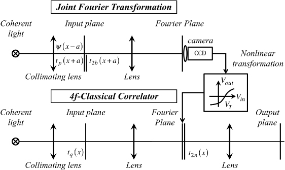
Figure 5. Scheme of the optical processor for secure multifactor authentication. The system combines a JTC and a 4f-correlator.
Download figure:
Standard imageOptical ID tags [116] have been shown as a good application of the optical encryption techniques for real-time remote authentication tasks. They enable surveillance or tracking of moving objects and they can be applied in a number of situations in transportation or industrial environments. A distortion-invariant ID tag permits the verification and authentication of the information contained in it even if the tag appears rotated or scaled or affected by some aberration [117]. As an additional degree of security, the ID tag can be designed so that it is only captured in the NIR (near infrared) band of the spectrum. In this way, data are no longer visible to the naked eye and only by using the adequate sensor is it possible to grab the correct information. In [118] the authors present a compact technique for encryption and verification that relies on these four principles: multifactor encryption, which permits the simultaneous verification of up to four factors; distortion-invariant ID tag for remote identification; NIR writing and readout of the ID tag signal for invisible transmission; and an optical processor, based on joint transform pattern recognition by optical correlation, for automatic verification of information. A highly reliable security system is obtained by combining the advantages of all these techniques.
The integration of photon-counting imaging and optical encryption may also improve information authentication robustness against intruder attacks. Photon-counting has been applied to either the input image or the encrypted function [119, 120]. In both cases, the decrypted signal, which also looks like noise, is not intended to be recognized by visual inspection, but instead it is correlated with the primary image for verification. Thus, the integration of photon-counting imaging along with DRPE and nonlinear correlation introduces additional layers of information protection that increase the system security and make the verification process more robust against unauthorized attacks. Two more interesting properties of this method have been outlined: even though the method was first intended for verification and not for image visualization, image retrieval is still possible by taking into account the pattern identification obtained from a peaky correlation signal; additionally, the method permits substantial bandwidth reduction and phase data compression when photon-counting imaging is applied to the encrypted function.
4. Improved hybrid systems and architectures for optical–digital correlation
In addition to the applications described so far in sections 2 and 3, there has been a continuous interest in improving the quality of correlation and enhancing the correlator architecture performance for a variety of pattern matching purposes.
An important issue is the effect of aberrations, because, very often, the optical systems involved in the recognition process are assumed to be aberration-free, particularly in simulated experiments or numerical calculations. The influence of aberrated convergent Fourier transform optical systems in optical correlation and pattern recognition has been studied for the Vander Lugt [121] and the JTC [122] architectures. In the case of the JTC architecture, the authors conclude that the aberrations on the first transform induce space variance in the final correlation, whereas the aberrations on the second transform produce a global decrease in the heights of the correlation peaks. By selecting a suitable combination of positions of the two acquisition planes of the JTC (the joint power spectrum plane and the correlation plane), it is possible to compensate for both effects to a certain extent and to find an optimal configuration in which the correlation peaks are sharp and almost invariant [122]. Optical correlators generally require to be illuminated with a monochromatic point source. Some drawbacks derived by such an illumination (coherent noise, low efficiency, mechanical stability requirements, monochromatic input) can be overcome by the use of natural light (spatially incoherent and broadband white light). Spatially incoherent, dispersion-compensated optical correlation can be achieved by the architectures described in [123, 124]. Applications of such totally incoherent optical processors in securing and encrypting information have been reported in [125]. Optical correlators illuminated by spatially incoherent and broadband white light sources are able to process self-luminous colour inputs, and some specific designs [126] show scale-tunable capabilities that can be advantageously utilized in colour pattern recognition. A time-multiplexing technique employing a colour filter wheel and a SLM to create achromatic or wavelength compensated diffraction patterns has enabled the development of a highly efficient experimental three-channel (RGB) JTC useful for real-time polychromatic object detection [127]. Changes in the illumination (i.e. the spectral power distribution of the light source that illuminates the colour objects) may cause serious difficulties in recognizing polychromatic colour patterns. Some studies have addressed the problem of finding pattern recognition algorithms based on optical correlation that are resistant against changes in the light source [70, 128, 129]. In [70, 128], the authors propose using uniform colour spaces (e.g. CIELAB is inspired in approaching such a uniformity), which are more stable under changes of the illuminant. A step forward is proposed in [129] with the introduction of a linear model, based on principal-component analysis, that represents the spectral reflectance function of each image pixel on a suitable basis for linear representation. A multichannel correlation is then applied all over the spatial distribution of the coefficients derived from the linear representation of each reflectance function. When the spectral power distribution of the illuminant is unknown, the authors apply an illuminant-estimation hypothesis before the correlation. In addition to multichannel methods, single-channel methods are used in colour pattern recognition as well. These methods are based on encoding the colour information into a certain complex distribution that can be processed by a single filter. A single-channel method combined with the so-called sliced orthogonal nonlinear generalized correlation [130], which achieves better discrimination than linear filtering and can be easily implemented by use of a time sequential JTC [131, 132], has been successfully used to detect a polychromatic target in scenes degraded by high levels of substitutive noise [133].
Another important issue concerns correlator compactness and reduction of alignment requirements. In this line of research, a lensless Vander Lugt optical correlation using two phase-only SLMs (figure 6(a)) has been proposed in [134]. Each SLM is used to display an input image in phase-only form (either the scene to analyse or the correlation matched filter) and a programmable phase Fresnel lens. Thus, the system has a simple construction and it is easy to achieve true alignment. Further compactness can be achieved by using a single SLM combined with a mirror (figure 6(b)), as is demonstrated in [135]. In such a case, the use of programmable phase Fresnel lenses with chromatic compensation [136] makes these compact correlators suitable for polychromatic pattern matching.
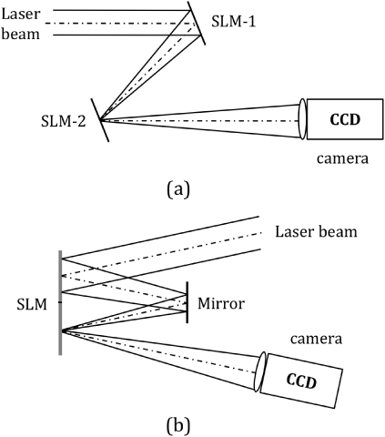
Figure 6. Principle of compact lensless Vander Lugt correlators: (a) with two phase-only SLMs, and (b) with one phase-only SLM and a mirror.
Download figure:
Standard imageThe shape and intensity of the correlation peaks, which is generally pattern-dependent, is an issue of interest for different reasons. In many applications, sharp and narrow correlation peaks are highly appreciated for an improved detection and accurate location of the target in the scene. In this sense, some methods that enhance the contrast between the autocorrelation and the cross-correlation peaks are based on image interleaving. This procedure consists of redistributing the pixels within the input image (usually a segmented target or object) according to a given rule, and is applied in a pre-processing stage before displaying the signal on the SLM of the correlator [137, 138]. In other applications, however, the robustness of classical matched filtering against noise and the calculation of shape-based correlation metrics instead of magnitude-based correlation metrics are preferred to enhance detection and position accuracy. For example, in the Lawrence Livermore National Laboratory, the scientists of the National Ignition Facility use real-time matched filtering and analysis of the correlation peak shape to direct 192 high-energy laser beams with precise alignment to achieve ignition of a deuterium–tritium fusion target, which involves temperatures approaching 100 million K and pressures at 100 billion atmospheres [139].
The design of correlation filters has evolved in many and different directions. In contrast to the simple matched filter, which is matched to a single training image, a composite filter allows the use of a set of training images and is capable of recognizing a target with tolerance to noise and a variety of distortions. The simulated annealing algorithm is a technique of synthesizing matched filters capable of discriminating almost similar patterns [140, 141]. This algorithm has been used to synthesize bipolar matched filters that provide rotation invariance for CCD and thermally captured images [142]. Synthetic discriminant function filters [82] are attractive for distortion-invariant pattern recognition and can be implemented on phase-only SLMs [143]. An algorithm has been proposed for an adaptive phase-input JTC that uses phase-only synthetic discriminant functions to generate a phase-only reference image that contains information about a target and its variants to be detected, and unwanted objects including a background to be rejected [144]. The system guarantees a given value of discrimination capability and is able to take into account the calibration look-up-tables of all optoelectronic elements used in real experiments. Due to the large number of designs for composite filters, it is often unclear how to select the best design for a particular application. A useful theoretical survey and empirical comparison of several popular composite correlation filter designs is reported in [145].
Although JTC is frequently preferred to the 4f Vander Lugt correlator because the optical setup is less sensitive to misalignments and the reference target is easily introduced in the spatial domain, there are some applications for which the Vander Lugt correlator is still advantageous. Using a photorefractive material for dense holographic storage [146], it is possible to perform real-time shift-invariant correlation in the Vander Lugt architecture to achieve a much higher recognition system operational speed than what the JTC architecture would allow. Some photorefractive polymers have demonstrated the capability of stable dynamic video-rate operation and a long shelf lifetime at room temperature [147]. A high degree of two-dimensional (horizontal and vertical) shift invariance in the recognition system is possible because of the material thinness. Such a high degree of real-time shift-invariant correlation is attractive in automatic target recognition, which not only includes detection and recognition but typically also includes tracking [148]. Tracking involves the connection of a target's locations over time to determine its path. Unlike the classical approach, which divides the three tasks (detection, recognition, and tracking) into stages and solves them separately, a more integrated approach will lead to obtain better results [149, 150]. Multi-frame correlation filtering is a framework to improve the link between detection and tracking in the context of correlation filtering. The goal of the approach is not to compute individual target tracks but rather to produce better output arrays by combining information from several correlation outputs over time (mapped into probability values for target location) before thresholding. By introducing a target motion model, represented by a 2D probability mass function that gives the probability that a target will jump from its current location to any other nearby location in the next frame, it is possible to combine an array of prior probabilities for the next frame with the correlation output values from the succeeding frame to yield an enhanced probability map to threshold for more robust target detection. Simulation results on forward-looking infrared video sequences show that this framework can significantly reduce the false-alarm rate of a bank of correlation filters while requiring only a marginal increase in computation [151].
5. Conclusions
So far, in 21st century, there has been a progressive convergence of optical correlation and digital methods for pattern matching. Along with this, related areas of research on optoelectronic devices, light sources, photosensitive materials, algorithms, and system architectures, among others, have also experienced great progress and have contributed to the development of solutions to modern and challenging pattern recognition problems. Electronic devices and computers are common components in many optical setups, and it is not strange to find digital techniques that rely on optics. With the rapid progress of digital computers, much faster than optical processors, computers currently implement many algorithms initially developed for optical pattern recognition. Thus, optical techniques are still a source of inspiration for pattern recognition algorithms, which can be implemented either optically or digitally, or under a hybrid scheme. Optics becomes even more relevant when it can bring something that is either difficult for electronics to do or perhaps not do at all.
In this review paper on advanced optical correlation and digital methods for pattern matching, three main areas of research have been described where a combination of optical correlation and digital methods cover the majority of applications: three-dimensional (3D) object correlation and recognition, correlation in biometric verification and optical security, and improved hybrid systems and architectures for optical–digital correlation.
In 3D object correlation and recognition, a variety of methods based on multiple viewpoint projections, digital holography, Fourier transform profilometry, and range images have been described. Although all of them introduce a third dimension (depth) to enhance identification and discrimination capability, a complete recognition of a 3D object with an arbitrary rotation in space is still a challenge that cannot be fulfilled without significantly increasing the computational burden of the hybrid optical–digital correlator. In addition to this, the colour content of the 3D object is often neglected and only a few methods have attempted to consider full 3D and colour information in pattern recognition.
Biometric verification and optical security techniques have experienced great development to provide solutions to real-world demands on secure authentication and information transmission in the period covered by this paper. Biometric verification has to face object variability, often associated with either meaningful minutiae or non-relevant changes in position, scale, and perspective. An advanced correlation filter and a number of training images must be chosen carefully. While too many training images are difficult to deal with and lead to complex training and testing stages, too few training images may lead to an insufficient generalization and unreliable verification performance. Multimodal or multifactor recognition, based on a combination of biometric signatures, reinforces authentication and the use of encryption–decryption systems contributes in keeping the signature secret. Optical correlators have proved to be efficient processors to carry out these tasks. The introduction of nonlinear operations in the encryption–decryption algorithm makes optical processors highly resistant to a wide variety of intruder attacks.
Finally, many aspects remain as open issues to investigate for an improved correlation-based pattern matching. From the signal degradation caused by optical aberrations to the alignment requirements and system compactness, from a matched filter design that controls the correlation peak properties to the massive optical storage of target information, from the integration of different spectral bands to automatic target detection, recognition and tracking of objects in movies, from pattern matching applications that have human visual perception as a reference to applications that aim to project the recognition system capabilities beyond the human senses, all these topics and many others have been investigated and reported through a vast list of scientific papers, conferences and meetings. The stress made on either the optical or the digital realization of the pattern matching algorithm, in part or as a whole, is generally dependent on the application. As the progress achieved in the past two decades demonstrates, it cannot be taken as a competition of techniques, but instead, as an opportunity to merge their potentials and hence, to produce totally new and more powerful solutions.
Acknowledgment
This research work has received financial funding from the Spanish Ministerio de Economía y Competitividad y Fondos FEDER (project DPI2009-08879).