
Abstract
For total reflection of a pulsed light beam at the interface between vacuum and a negative permittivity medium, the electromagnetic fields and the associated energy-flux patterns in the two media are investigated analytically and numerically. For a TE (transverse electric) polarized pulsed beam with positive Goos–Hänchen shift, energy reflection occurs not only in the second medium but also in the first medium because of interference between the incident and reflected fields. However, for TM (transverse magnetic) polarization where the Goos–Hänchen shift is negative, reflection of energy flux occurs in the first medium (or in front of the interface). At the same time, the energy flux around the interface forms time-dependent loops which absorb energy from the incoming flux in the front edge of the pulse but release energy into the outgoing flux in the later edge of the pulse to ensure energy conservation. Therefore, the so-called causality paradox in TM polarization is caused by the fact that interference between incident and reflected fields in the first medium and energy-flux loops around the interface offer a shorter path for reflection of energy flux (or photons).
Export citation and abstract BibTeX RIS
1. Introduction
When total reflection occurs at an interface separating two semi-infinite homogeneous media, the reflected beam undergoes a lateral shift with respect to the path predicted by geometrical optics. This phenomenon is referred to as the Goos–Hänchen (GH) effect which was demonstrated by Goos and Hänchen [1] and was theoretically explained by Artmann [2]. So far, this phenomenon, occurring in both reflection and transmission of a light beam on various configurations, has been widely analyzed both theoretically [3–17] and experimentally [18–20]. Meanwhile, the time delay associated with the GH shift (named as the GH time) has also been investigated according to the stationary phase theory which gives the phase time [21–23] and the new energy-flux method [24, 25]. The phase time (the sum of the time delay caused by media dispersion and the GH time) was consistent with experimental results [26–28], but it could result in a causality paradox [29, 30] in total reflection with a negative GH shift. Recently, we [31] have investigated the effect of the GH shift on the total internal reflection of a pulsed light beam. Although the electromagnetic field of the reflected pulsed beam undergoes position-dependent distortions because of frequency-dependent GH shifts, the time delay of the reflected field agrees with the phase time. According to Lai's work [5], which shows the energy-flux pattern around the interface, we have explained the causality paradox by considering that total reflection occurs in front of the interface [32]. But this simple explanation does not stand up to in-depth study. Why does light know the interface is there before it reaches the interface? Where does the energy in the closed-loop flux lines in figure 6 of [5] come from? For monochromatic light beam incidence, the energy-flux pattern is static, which cannot answer these questions. Therefore, an investigation of the energy-flux pattern in total reflection of a pulsed light beam is needed to show the dynamic process of the reflection of energy flux.
In this work, we consider total reflection of a pulsed light beam on an interface between vacuum and a negative permittivity medium. By referring to Lai's analysis [5] which deals with a monochromatic light beam, the electromagnetic fields of the pulsed beam in the two media are investigated analytically, and the time-dependent energy-flux patterns around the interface are calculated numerically. For TM (transverse magnetic) polarized pulsed beam incidence, the energy flux across the interface forms time-dependent loops which exchange energy with the pulsed beam, differing from Lai's static and closed loops [5]. In the front edge of the pulse, the loops absorb energy from the incoming flux, but in the later edge of the pulse, the energy stored in the 'loops' will gradually return into the outgoing flux to ensure energy conservation. It is also shown that, because of the existence of energy-flux loops and the interference between the incident and reflected fields, the energy in the pulsed beam is reflected in front of the interface. Therefore, the so-called causality paradox does not exist from the viewpoint of the reflection of energy flux. The energy flux for TE (transverse electric) polarization is also calculated for comparison, which shows that energy reflection occurs in both media, as is shown in [5, 17].
2. Electromagnetic fields in two media
Consider that a TE- or TM-polarized plane wave is incident from vacuum (ε1 = 1) upon a homogeneous medium (ε2) with real and negative permittivity, which is shown in figure 1, with an incident angle of θ. The reflection and transmission coefficients are
where φ is the phase shift of the reflected wave, the phase shift of the transmitted wave is exactly φ/2, and q is 1 for a TE wave and is 1/ε2 for a TM wave. The GH shift of the reflected wave is given by D =− (1/k) dφ/dθ, where k = ω/c with c the speed of light in vacuum and ω the angular frequency of light, and the associated time delay (GH time) is Δτ = (Dtanθ)/c [21–23]. The so-called causality paradox can occur for a TM wave because of D < 0 and Δτ < 0 [29–32]. In this work, the negative permittivity medium (ε2) is assumed to be nondissipative, or |r| = 1, so that an angular shift does not appear [4]. We also consider that the medium ε2 is nondispersive, which means that ∂φ/∂ω = 0 and the GH time is equal to the phase time [29], so we can focus our attention on the causality paradox resulting from the GH time.

Figure 1. The pulsed beam is incident from vacuum on the interface with the beam axis coinciding with the z' axis. Three coordinate systems are used, namely the incident x'y'z' coordinate system, the reflected x''y''z'' coordinate system, and the original xyz coordinate system.
Download figure:
Standard imageNext, consider a TE- or TM-polarized pulsed light beam illuminating the interface from vacuum. Three coordinate systems introduced by Lai [5] are employed, as shown in figure 1, namely the incident x'y'z' coordinate system, the reflected x''y''z'' coordinate system, and the original xyz coordinate system. The pulsed beam is two-dimensional, that is to say, ∂/∂y = 0 is assumed to be true. The axis of the incident beam coincides with the z' axis, making an angle of θ0 with the z axis. The x'' axis is chosen so that an incident plane wave with wavevector ( ) is reflected into the reflected plane wave with the same wavevector (
 ), which means that the unit vectors along the y', y, and y'' axes have the relation
  .
.
It is known that a pulsed beam is a superposition of a series of plane wave components characterized by  (or the incident angle θ) and the angular frequency ω. The spectrum (including the frequency spectrum and the angular spectrum) of the magnetic field for the TM-polarized incident pulsed beam is expressed as

where Ω = ω − ω0 with ω0 the carrier frequency of the pulsed beam, and the superscript (i) denotes the incident field. Both the frequency spectrum and the angular spectrum are assumed to be Gaussian functions of
where σ gives the width of the beam at the waist located at z' = 0,  with τp denoting the duration of the pulse at FWHM (full-width at half-maximum of the intensity profile). Note that the electric field should be used when the pulsed beam is TE-polarized. The magnetic field of the pulsed beam is given by
in the incident coordinate system. As is shown in equation (17) of Lai's work [5], the integral about  results in a Gaussian beam
  with an angular frequency of ω which propagates along the z' axis. And then, the integral about ω (or the superposition of all Gaussian beam components with different ω) is rather complicated. In this work, we try to give analytic expressions for all fields which are more interesting and of more physical meaning than numerical calculations, so Lai's approximation [5] of
  is used because we only discuss the fields and the associated energy flux around the interface. With this assumption, the integral about
  in (4), or
  , gives the incident beam component with an angular frequency of ω, that is

and
So the magnetic field of the pulsed beam is given by  , which is

where G and τi are defined as
According to (5) and  , where ε0 is the permittivity of vacuum, the electric field of the incident beam component with an angular frequency of ω is

For TE polarization,  should be used to obtain the magnetic field. The electric field of the incident pulsed beam is
  . By applying the approximation of
  and considering
  , we have
The electric and magnetic fields of the incident pulsed beam in the original xyz coordinate system can be easily obtained by using the transformations
The spectrum of the reflected pulsed beam is  . By using the same method, the reflected beam component with an angular frequency of ω is obtained as [5]

where D = D(ω) is the ω-dependent GH shift of the ω-beam component, φ0 = φ(θ0), and the superscript (r) denotes the reflected wave. We define D0 = D(ω0), that is the GH shift of the ω0-beam component. For a pulsed beam with a large beam waist, D − D0 ≪ σ holds true, and (12) can be approximately expressed as

The magnetic field of the reflected pulsed beam is given by  , which is

where
At the point (x = D0/cosθ0,z = 0) from which the axis of the reflected pulsed beam departs, the time delay of the reflected field in total reflection is τ = z''/c = (D0tanθ)/c by comparing G(τr = 0) in (14) and G(τi = 0) in (7), which is equal to the phase time obtained from the stationary phase theory [29, 32]. The electric field of the reflected beam component with an angular frequency of ω is given by  , which is, by considering the relation
  ,
,
So the electric field of the reflected pulsed beam is  . By considering
  and
and  , we have
The fields of the reflected pulsed beam in the original xyz coordinate system are then obtained by using the transformations

According to equation (30) in [5], the transmitted beam component with an angular frequency of ω is given by
where t0 = t(θ0),  with κ = ka (the skin depth of the field in the second medium is 1/κ),
  , α = qaD/(2cosθ0), β = sin(2θ0)/(2a),
  , and the superscript (t) denotes the transmitted wave. So the magnetic field of the transmitted pulsed beam is
  . For a pulsed beam with a large beam waist, D − D0 ≪ σ holds true, so we have
  and α ≈ qaD0/(2cosθ0). Therefore, the magnetic field is
where

According to (19) and  , we have [5]
Since  is a small value, it can be approximately expressed as
  with k0 = ω0/c. Therefore, the electric field of the transmitted pulsed beam is
3. Energy-flux pattern around the interface
For total reflection of a TM-polarized pulsed beam, the time-averaged Poynting vector is given by

where 'Re' and '∗' represent 'the real part of' and complex conjugate. In the first medium, the time-averaged Poynting vector can be divided into three parts,

where ![${\vec{S}}_{\mathrm{i}}=(1/2)\mathrm{Re}[{\vec{E}}^{(\mathrm{i})}\times ({\vec{H}}^{(\mathrm{i})})^{\ast }]$](https://content.cld.iop.org/journals/2040-8986/14/8/085701/revision1/jopt424948ieqn156.gif) is the incident energy flux with the expression
is the incident energy flux with the expression
![${\vec{S}}_{\mathrm{r}}=(1/2)\mathrm{Re}[{\vec{E}}^{(\mathrm{r})}\times ({\vec{H}}^{(\mathrm{r})})^{\ast }]$](https://content.cld.iop.org/journals/2040-8986/14/8/085701/revision1/jopt424948ieqn158.gif) is the reflected energy flux and is given by
is the reflected energy flux and is given by

and

is the interference term. It is noted that these results can be used for a TE-polarized pulsed beam just by making the transformation of ε0 → μ0. When the interference term is not taken into account, we have the following conclusion according to (25)–(28): if the maximum (or the peak) of the pulse appears at the point (x = 0,z = 0) where the axis of the incident flux ends at the time τ = 0, the maximum of the reflected pulse will appear at the point (x = D0/cosθ0,z = 0) from which the axis of the reflected flux departs at the time τ = (D0tanθ0)/c. So the time delay of the reflected energy flux during reflection is (D0tanθ0)/c, which is exactly the phase time. When D0 < 0, both the time delay of the reflected field and that of the reflected energy flux are negative, which means that photons are reflected on the interface before they arrive and the causality of relativity is obviously violated. Fortunately, this conclusion is wrong because the interference term expressed as (28) will change the flux pattern in the first medium, so the time delay of energy flux during reflection is not (D0tanθ0)/c. Therefore, the phase time is the time delay of the reflected field, but it cannot be used to represent the time of energy-flux reflection in the interference region.
The time-averaged Poynting vector in the second medium  is given by
for a TM-polarized pulsed beam. The Poynting vector for TE polarization can be obtained just by making the transformation of ε0ε2 → μ0. So when ε2 < 0, the signs of S2x and S2z in TM polarization are opposite to those in TE polarization, indicating a backward flow of energy for TM polarization [5].
Consider a TM-polarized pulsed beam with parameters of τp = 50 fs, σ = 5 μm, and k0 = 7.85 × 10⁶ rad m−1 (k0σ = 39.3), illuminating from vacuum (ε1 = 1) on a negative permittivity medium with θ0 = π/4. ε2 is chosen to be a small value of − 0.15, the same as that in [5], so that the transmitted energy flux has a relatively large magnitude according to (29). The GH shift is D0 = 5.83 × 10⁻⁸m ≪ σ. The energy-flux pattern at the time τ = 0, or the time that the peak of the pulse arrives at the origin (x = 0,z = 0), is shown in figure 2, where the effect of the interference term on the flux pattern is demonstrated by the interlacing of the large and small magnitudes of the Poynting vectors in the z-direction, and a backward flow of energy appears in the second medium. In order to show the process of energy-flux reflection for the pulsed beam, the energy-flux patterns across the interface at different times are shown in figure 3, where the parameters are the same as those in figure 2, but the z axis and the z-component of the Poynting vector, Sz, are magnified tenfold. The times τ are selected as to be − 20 fs, − 10 fs, 0 fs, 10 fs and 20 fs, corresponding to (a), (b), (c), (d), and (e) in figure 3, respectively. The following is concluded from figure 3. (1) The flux patterns across the interface form energy-flux loops because of the backward energy flow associated with the evanescent wave in the second medium, as is shown in figure 6 of Lai's work [5]. (2) The loops are time-dependent and exchange energy with the pulsed beam, which is different from Lai's static and closed loops [5]. Time-dependent energy-flux loops in the region of − 0.1 μm < z < 0.1 μm are shown in figure 4. In the front edge of the pulse, it is seen from (a) and (b) of figure 4 that the loops absorb energy from the incoming flux, because the z-component of the Poynting vector, or Sz, has a large value in the region of − 5 μm < x < 5 μm on the z =− 0.1 μm plane in (a) and (b) of figure 4. So, part of the z-component energy flux in the incident pulsed beam penetrates the z =− 0.1 μm plane and enters the loops. For τ = 0 fs (or the time that the peak of the pulse arrives at the origin (x = 0,z = 0)), as is shown in (c) of figure 4, we can see that Sz < 0 for x < 0 and Sz > 0 for x > 0 on the z =− 0.1 μm plane, which shows that the loop both absorbs and releases energy. At the same time, the magnitude of the energy-flux loop reaches its maximum value by comparing all the panels of figure 4. In the later edge of the pulse, as is shown in (d) and (e) of figure 4, the magnitude of the energy flux in the loops decreases with the decrease of the incident field because part of the z-component energy flux in the loops (Sz on the z =− 0.1 μm plane) penetrates the z =− 0.1 μm plane and enters the reflected pulsed beam. Therefore, the energy stored in the 'loops' will return into the outgoing flux gradually to ensure energy conservation. Therefore it can be concluded that the energy in the loops comes from the incident energy flux and will join into the reflected energy flux eventually. For a time-dependent pulsed beam incidence, the loops are also time-dependent because all fields (incident field, reflected field, and transmitted field) must comply with time-dependent Maxwell equations and their boundary conditions on the interface, and are consequently time-dependent. (3) The total energy in the region of the loops is very small, that is to say, the energy that can arrive at and (or) go through the interface is only a small part in the total energy of the whole pulsed beam, so the main part of energy in the pulsed beam is reflected in front of the interface because of the existence of energy-flux loops across the interface and the interference between the incident and reflected fields. The statement 'photons are reflected on the interface before they arrive' is obviously wrong. In fact, it is the existence of energy-flux loops across the interface that makes the energy flux (or photons) find a shorter path to propagate energy in the pulsed beam, which also explains the question of why the light knows that the interface is there before it reaches the interface. In the case of plane wave incidence where the energy flux is static, the point of energy reflection can be simply considered to be located at the point of intersection of the incident wave and the reflected wave, as is shown in [32]. Therefore, it can be concluded that from the viewpoint of the reflection of energy flux, a causality paradox occurring on the interface does not exist because of the existence of energy-flux loops and the interference between the incident and reflected fields.

Figure 2. The energy-flux pattern at the time τ = 0, where τp = 50 fs, σ = 5 μm, k0 = 7.85 × 10⁶ rad m−1, ε1 = 1, ε2 =− 0.15, and θ0 = π/4.
Download figure:
Standard image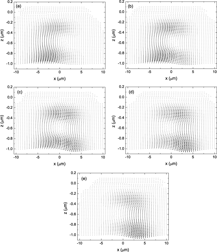
Figure 3. The energy-flux patterns around the interface at different times of τ: (a) − 20 fs, (b) − 10 fs, (c) 0 fs, (d) 10 fs, and (e) 20 fs. The z-coordinate axis and the z-components of the Poynting vectors are magnified tenfold. The parameters are the same as those in figure 2.
Download figure:
Standard image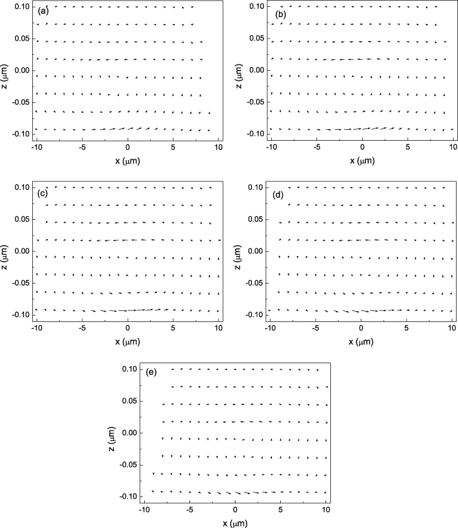
Figure 4. Time-dependent energy-flux loops in the region of − 0.1 μm < z < 0.1 μm at different times of τ: (a) − 20 fs, (b)− 10 fs, (c) 0 fs, (d) 10 fs, and (e) 20 fs. The parameters are the same as those in figure 2. This figure is a zoom-in of the − 0.1 μm < z < 0.1 μm region in figure 3.
Download figure:
Standard imageFor total refection of a TE-polarized pulsed beam with the same parameters as those in figure 2 and D0 = 2.23 × 10⁻⁷ m, the flux patterns around the interface are shown in figure 5, where the times τ are selected as − 10 fs, 0 fs, and 10 fs, corresponding to (a), (b), and (c), respectively. We can see that a small part of the incoming flux penetrates into the interface to become an evanescent wave and returns into the outgoing flux because a positive GH shift is associated with forward energy flow in the second medium. At the same time, the whole energy flux in the pulsed beam is reflected closer to the interface than for TM polarization. By comparing figures 3 and 5, we can see that the energy flux (or photons) for a TM-polarized pulsed beam chooses a shorter path to be reflected than that for a TE-polarized pulsed beam, which explains why the phase time is negative for TM polarization but positive for TE polarization.

Figure 5. The flux patterns around the interface at different times of τ: (a) − 10 fs, (b) 0 fs, and (c). The z-coordinate axis and the z-components of the Poynting vectors are magnified tenfold. The parameters are the same as those in figure 2.
Download figure:
Standard image4. Conclusion and discussion
For total reflection of a pulsed beam on the interface between vacuum and a negative permittivity medium, the electromagnetic fields in the two media are investigated analytically, and the time-dependent energy-flux patterns around the interface are calculated. For TM polarization with a negative GH shift, the flux patterns around the interface form time-dependent energy-flux loops, and the energy in the loops comes from the incident energy flux and will join into the reflected energy flux eventually. Because of energy-flux loops and interference between incident and reflected fields, the energy in the pulsed beam is reflected in front of the interface. Therefore, the so-called causality paradox does not exist from the viewpoint of the reflection of energy flux.
Finally, we would like to say that the phase time is not wrong. According to equations (14) and (15), the time delay of the reflected field is exactly the phase time both in the interference region and in the non-interference region. For the time delay of the reflected energy flux, we should consider the following two aspects. In the non-interference region, the expression of the reflected energy flux is  , expressed as equation (27), because the interference term
  is zero, which also agrees with the phase time. However, in the interference region, there is only the total energy flux, expressed as equation (25), and the reflected energy flux is meaningless because of the interference term. Therefore, we believe that the phase time agrees with the expression of the reflected pulsed beam (including both the reflected field and the reflected energy flux) in the non-interference region. Why does the phase time result in a causality paradox? The reason lies in the fact that, in the derivation of the phase time, the incident point of the beam axis located on the interface (or the origin of the coordinate system in figure 1) is considered as the reference point, but the energy flux is reflected in front of the interface, that is to say, the energy-flux loops and the interference between the incident and reflected fields work together to offer a short cut for propagation of energy flux.
Acknowledgments
This work is supported by the National Natural Science Foundation of China (10804076) and the Natural Science Foundation of Hebei Province of China (F2008000450).