
Abstract
This paper reviews the rapid advances that have been made in one form of optical biological imaging in the last decade, namely that of light sheet microscopy. Although the concept was originally presented over one hundred years ago, at the time it was a methodology that lacked the technology to really make it a viable tool for practical everyday imaging in the biologist's laboratory. However, since its re-discovery, it has started to transform in vivo and increasingly intact organ imaging in a number of areas of biology. This review looks back at the beginning of the method and then the crucial role that modern optical technology, frequently developed for other fields, has played in advancing the instrumentation. This paper will also look at the OpenSPIM route that was developed whereby, through the purchase of a few optical components, researchers have been able to develop their own bespoke instruments and we consider if this may be a route forward for the rapid development of other technological breakthroughs.
Export citation and abstract BibTeX RIS

Original content from this work may be used under the terms of the Creative Commons Attribution 3.0 licence. Any further distribution of this work must maintain attribution to the author(s) and the title of the work, journal citation and DOI.
1. Introduction
Ever since the use of the first simple magnifying lenses, there has been a desire to image life with increased resolution. The development of more complex multiple lens systems, around 400 years ago by people such as Robert Hooke, led to the discovery of cells, bacteria, and the plethora of biological activities taking place at levels below the visible resolving power of the human eye. A major desire of the life scientist thus grew to be the observation of life at high spatial resolution and, increasingly, in three dimensions for extended periods of time. The development of the light sheet microscope [1] over the past ten years has been at the forefront in this quest for in vivo imaging with minimal perturbation to the sample. The rediscovery of the concept also came at just the right time in terms of technical advances in instrumentation and perhaps also in a wider context, in the way that knowledge is now disseminated and this has helped to advance the field, probably, more rapidly than other new microscopy techniques. As an indication, over 500 references to the technique were found in preparation for this optical review of light sheet microscopy, many in the highest profile journals. This review initially looks at the background and basic optical principles involved in light sheet microscopy, before examining the rapid optical advances that have been made to improve both the quality of the images and the versatility of the method.
The first recorded manifestation of the light sheet microscope was in 1912 when a German chemist, Richard Zsigmondy, and a physicist, Henry Siedentopf, worked together to develop improved methods of understanding colloidal gold. They wished to push the resolution of optical microscopes to observe these nanostructured materials. However, it was already well established that there was a limit to the resolution possible, based on the work by Abbe, and that one needed to use lenses with a high numerical aperture (NA) and short wavelengths of light for the maximum resolution possible. Crucially to Zsigmondy and Siedentopf, an employee with Zeiss at the time realised that, as well as maximising the optical resolution possible, one also needed high contrast images in order to maximise the visibility of any features. They thus introduced the light onto their microscope perpendicular to the observation axis and consequently only saw the light that was scattered by the gold nano-particles into their line of observation [2], in so called Tyndall cones, with the colour being dependent on the size and material of the particle. All observations had to be made by eye as photography had not yet advanced sufficiently to be employed routinely for microscopy, and the light source, although powerful, was variable as it involved focused sunlight. The experiments were recently repeated and further details can be found an interesting non-biological background paper [3], where the technique is called ultramicroscopy. Consequently, although the method worked well for the inventors and a few future collaborators, also looking at events that could be studied by observation of scattered light such as Brownian motion, and a commercial system was built by Zeiss, the technique was not widely accepted. This was probably due to the in-ability to record the events and the working distances (WDs) of high NA objectives, at the time was very short making the range of samples that could be viewed limited, mainly to colloidal suspensions.
It was thus about 80 years before the idea of using sheets of light to illuminate the sample was re-discovered. The main focus then was on the development of higher resolution imaging methods, and the concept of the light sheet was used to reduce the excitation volume [4–6]. This was followed eight years later by the use of a light sheet with an orthogonal camera to view water borne bacteria [7]. The light sheet here was not particularly thin as it was produced using a simple cylindrical lens with a low NA. Following these initial publications, many similar methods have surfaced, e.g. OPFOS, SPIM, HR-OPFOS, mSPIM, DSLM, TSLIM [8, 9], some of which will be mentioned later in this review. The introduction of the light sheet microscope, as it is now understood, was described in 2004 [1], which started the rapid growth of the technique. This instrument used the now ubiquitous orthogonally mounted microscope objectives with the light sheet being produced using a cylindrical lens before the illumination objective. With the advent of advanced, and now low-cost CCD and CMOS cameras, linked with the plethora of all solid-state frequency doubled laser sources, covering almost the complete visible spectrum, the technology was now readily available to deliver high performance imaging at a reasonable cost. The optical concept of the light sheet method is shown in figure 1. It was around this time that the acronym SPIM came into widespread use, standing for selective (or alternatively single) plane illumination microscopy, becoming a standard term particularly in the field of developmental biology. Thereafter, the acronym LSFM (which stands for light sheet fluorescent microscopy) was designated to describe all of the techniques based on light sheet illumination.

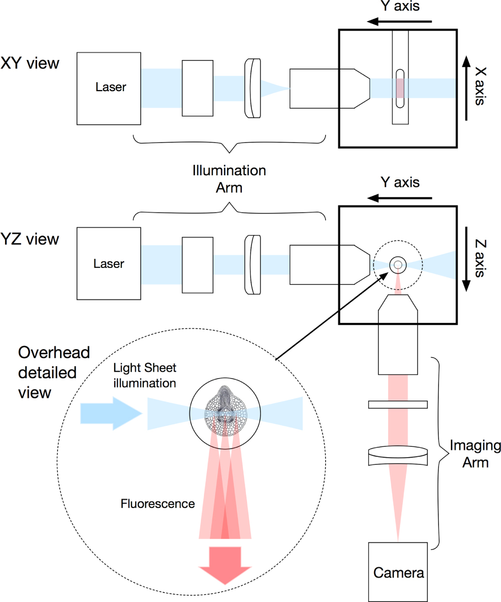
Figure 1. Concept of the LSFM method with the excitation light sheet produced using a cylindrical lens before the excitation objective and the orthogonal imaging arm. The top drawing shows the XY plane view, where the light is kept collimated by the objective unto the sample. The bottom drawing represents the YZ plane view, where the objective strongly focuses the light unto the sample. The addendum (image in the circle), shows in details on the collected fluorescence emitted by the sample.
Download figure:
Standard image High-resolution imageIn addition to the technological development, at this time, the use of genetically encoded fluorescent proteins was also revolutionising the study of in vivo biology, the inventors of the method being awarded the 2008 Nobel Prize in Chemistry [10]. This advance, and its implications for the optical methods employed to observe processes within the animal, are described later in this review. The other linked biological change was the increasing use of the humble zebrafish (Danio rerio) as a model organism, in particular for developmental studies. As the fish is basically transparent, or can be made transparent through the use of pharmaceutical compounds or genetic manipulation [11], optical imaging at depth within a living sample became viable. In their original publication [1] the Stelzer team also demonstrated the use of the technique in imaging developing Drosophila embryos and, shortly afterwards, the other main invertebrate model, C. elegans, was imaged by multiple groups, as again, it is fundamentally transparent. The method was then taken up by the plant community in particular for the imaging of root development over extended periods of time [12, 13].
1.1. Why light sheet microscopy is of such interest to life scientist
Before considering the optical and technical background and recent advances in SPIM, it is worth carefully considering why it has so rapidly become the imaging method of choice for significant numbers of research areas, ranging from brain imaging through to the study of heart disease and plant growth. As life can be thought of as a four-dimensional process consisting of three spatial dimensions and time, to truly understand what is taking place within a sample, one needs to observe the system for an extended period of time with minimal perturbation to the sample. Analysis of biological sample dynamics over time, or four-dimensional imaging, represents a major goal of biological science. The ability to resolve volumetric structures, within the cell or tissue, during developmental events, or in response to environmental or experimental stresses, is critical to the understanding of biological behaviour. Within this objective, LSFM has become the tool of choice [14] for many research groups, as SPIM was conceived for in vivo 4D imaging.
The conventional method for obtaining three-dimensional data sets in biology is through the use of a confocal microscope [15]. This provides the best possible optical sectioning and the system can be diffraction limited in all three dimensions. However, due to the presence of the pinhole, confocal systems are inherently based on scanning, normally of the imaging beam, and hence are limited to several tens of optical slices per second and, occasionally, up to a hundred optical sections a second in certain home built advanced systems. Therefore, to build up a three-dimensional image, one needs to repeat this optical sectioning at different depths within the sample, leading to volumetric imaging typically taking at least several seconds, and more routinely over 30 s in most situations. This means that three-dimensional dynamic effects are frequently missed. In addition, there is a significant risk of phototoxic events or photo-bleaching of the fluorophore. The excitation light illuminates not just the small volume of interest, but a cone of the sample above and below the focal volume. All of this out of focus excitation is wasted as the fluorescent photons are rejected by the pinhole in the confocal system. However, the excitation has taken place and thus there is a risk of photo-bleaching and other unwanted side effects from the light. So, for long term extended imaging, the method, although offering a very high spatial resolution, is comparatively slow, limited to a typical depth of around 50 µm and has a high risk of photo-bleaching and phototoxic events. The use of nonlinear excitation methods does increase the depth of imaging possible and removes out of plane bleaching (or offers no bleaching in the case of Raman or harmonic based methods) but still has to be beam scanned. In addition, the use of longer wavelengths, although reducing unwanted phototoxic events, can increase the risk of localised sample heating and damaging. Nonlinear excitation methods (e.g. CARS, multiphoton fluorescence, harmonic imaging) are also inherently more complex in terms of the light sources [16] and significantly more expensive.
The main advantage of light sheet microscopy is that a single optical section is illuminated at a time, and that the fluorescence from all of the molecules excited within that optical section, and within the field of view of the observing lens, are collected. Crucially, only the molecules within the imaging plane are excited, minimising the risk of phototoxic events [17]. The fact that one is collecting an entire optical slice in one go also means that camera-based detection is possible, and beam scanning is not required. This means that optical sections can be recorded very rapidly, enabling transient effects to be observed. Full XYZ high-resolution data sets can be recorded within seconds and, as will be described later, sub-second volumetric imaging is possible [18]. It thus became clear very quickly that, for live imaging, SPIM provided an ideal route to collecting 3D data [8, 19]. Since the first publications, there have been multiple reviews written for the different branches of biology, but the overriding message of the advantages of SPIM are 3D speed, minimal perturbation and acceptable resolution, and the limitations are now becoming better understood [20]. The optical sectioning method is now being linked with other more conventional widefield microscopy to provide the maximum quantity of data from a single experiment [21] helping to reduce the number of animals used in such research. The technique is also being applied to large specimens [22] as the understanding of the trade-offs between the resolution, the speed of imaging and volume are known.
LSFM imaging, therefore, provides biologists with a new tool to observe processes for longer periods of time in an in vivo situation. This review will now go on to look at the basic optical principles behind the method, before looking at the current state of the art techniques, where optical physics is pushing back the boundaries for rapid, deeper, less invasive imaging combined with high resolution. The link between the advances in technology will be closely related to the increased biological understanding that these advances enabled. We also explore areas where there are still technical challenges and where new optical methods are required to overcome the biologically imposed barriers.
2. Principals and practical implementation of light sheet microscopy
The core concept behind the light sheet microscope is very simple, and shown in figure 1. A sheet of light is produced and illuminates the sample, which in most biological systems is either fluorescently labelled or genetically modified to express fluorescent proteins. The fluorescence, which is emitted in all directions, is collected using a second microscope objective, which is perpendicular to the excitation sheet, thus capturing an entire optical slice [1, 23]. The collected light is then re-imaged onto a camera and, typically, the sample is moved through the light sheet to collect the next optical plane. The crucial step is in producing a uniform light sheet which is coincident with the focus of the observing lens.
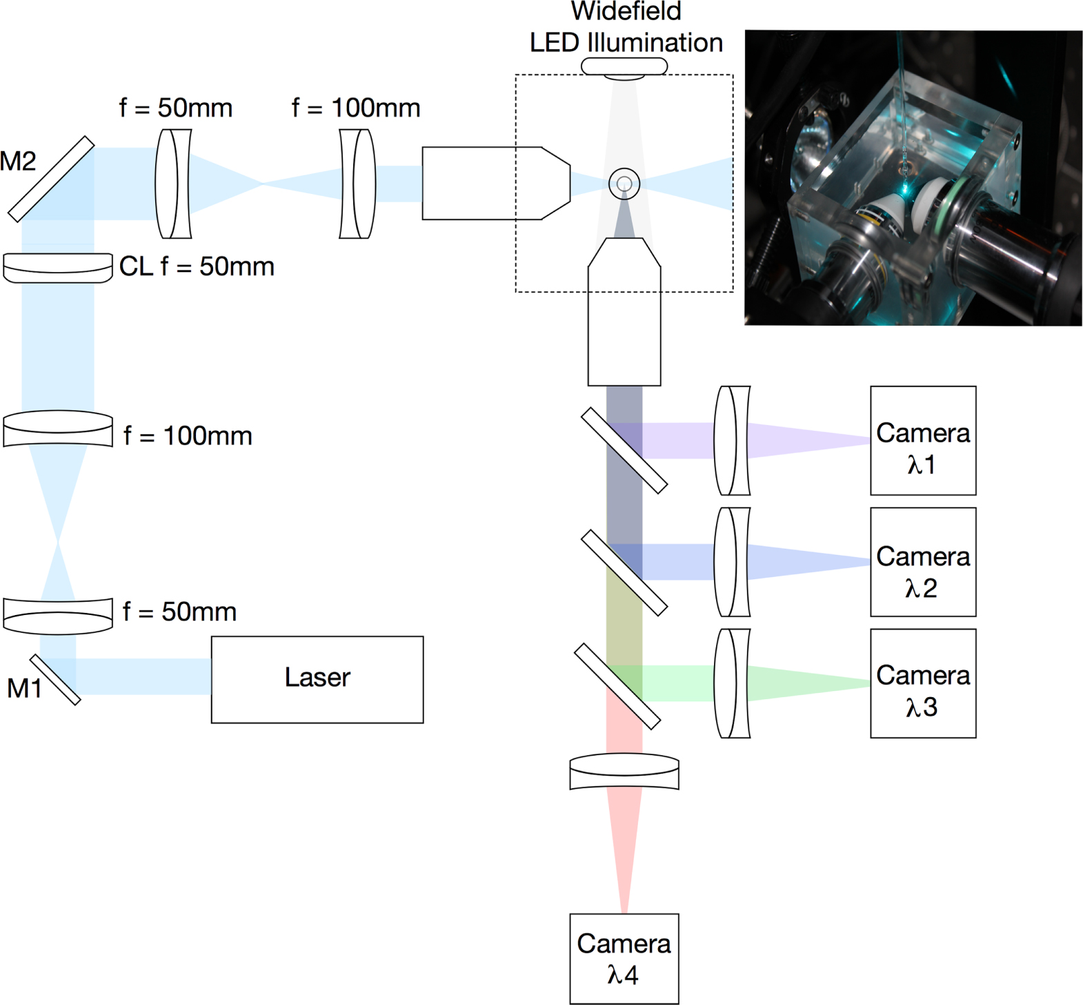
In figure 2, a practical implementation is shown, where light from a suitable laser source is expanded and directed through a cylindrical lens, and the resulting line of light being re-imaged into the back aperture of an objective lens. This line of light fills the full aperture of the illumination objective in one axis, leading to the full focusing power of the lens (determined by its NA). However, in the other axis, as only a very small portion of the back aperture is illuminated, the effective NA of the objective is now very small and hence the light is not focused. This leads to the formation of a sheet of light at the focus in which its vertical height is mainly determined by the power of the cylindrical lens, and the thickness of the sheet, by the NA of the objective. Typical lens values are shown in figure 2, and in our home built system the excitation objective has a magnification of 10 times, NA of 0.30 and WD in water of 3.5 mm (Nikon). This produces a light sheet of around 2 µm thickness over a field of view of around 150 µm. Clearly here, there is a compromise in terms of the light sheet, if a lens with a higher NA is used, one will have a thinner light sheet, however, the light sheet will not be as uniform across the full field of view of the observation objective. As will be discussed later, optical changes to the illumination source has been one of the areas in which optical advances have been made for improved imaging. Greater detail on the basic optical system and considerations given can be found in an earlier paper by Swoger and Stelzer [24] and some advance considerations of the use of a cylindrical lens in this configuration have also been reported [25]. The former paper also describes some of the more detailed considerations of the control hardware and selection of specific components. Variations on this basic illumination configuration can be found later in this review.

Figure 2. Practical multi-wavelength LSFM system with typical optical components and including widefield LED illumination (not drawn to scale).
Download figure:
Standard image High-resolution imageThe light has now reached the sample and a crucial consideration here is exactly how the sample is mounted. We are generally dealing with live and developing samples and, although normally anesthetised, they are still subject to movement. As the objectives typically used are water immersion lenses, the sample is normally mounted in low melting point agarose or water within a glass or fluorinated ethylene propylene (FEP) tube. The advantage of the FEP tubing is that it is approximately refractive index matched to the surrounding water, the disadvantage is that it is not optically perfect and thus can lead to an increase in scattered excitation light [26]. An alternative is to directly extrude the sample in the agar. All methods work and it is frequently down to a user's personal preference or sample. The sample needs to be able to be moved in the Z direction (through the light sheet) in order to record the images at different depths. Due to the complexity of having to keep both the light sheet position and imaging focus in the same plane, moving lenses is not the normal preferred way of depth scanning. Rotation of the sample is also a useful consideration as this helps with the alignment of the correct view into the camera. If this is automated, it also means that the same system can be used for a variation of optical projection tomography [27].
Having now correctly illuminated the sample, the critical factor in any optical microscope is the collection of the precious fluorescent photons. The optical properties, of the collection objective, determines the ultimate resolution of the system. Typically, as in our home built SPIM, systems use a water immersion objective with a NA of around 0.8 and a WD of 3.0 mm and x16 magnification (Nikon). The important practical considerations are the NA and the WD. If the WD is too short, the lens will hit the excitation objective before it is focused in the light sheet. The collected light is then re-imaged onto a suitable camera, or in the case of systems to be used with multiple fluorophores, a series of dichroic beam splitters can be used to a multiplicity of cameras. A useful addition to this basic configuration is an LED mounted behind the sample which can provide a wide field image which is very helpful when trying to first align a sample where a single optical slice can be difficult to interpret, especially in a sample with only certain cells, or organs labelled. This basic configuration has, however, been subject to a large number of variations, which are discussed below.
2.1. Improvements on basic illumination
The illumination system on a light sheet microscope is probably the most important consideration, and variable, as it provides the optical sectioning in the method and also the evenness of illumination across the sample. Consequently, there has been considerable interest in either improving the illumination or, more normally, optimising it for a specific application [28] and the range of different methods is now very large. Unless exotic beam forms are used (Bessel and Airy beams are discussed later), the main target has been to reduce sample scattering and absorption from affecting the image quality. The absorption when using both plants and fish can be a major issue, though in the case of fish, as mentioned above, this can be reduced either through the use of the 'Casper' no melanocyte fish [11] or with chemical agents to reduce melanin production, in addition to other tissue clearing techniques [29]. If the light sheet entering the sample does impinge on an absorption site, it means less light at the focus and hence dimmer images in certain areas, creating regions of shadow in the image. Scattering also leads to a loss of fluorescence excitation at the focus, but the situation can be made worse by the scattered photons causing fluorescence outside the focal volume leading to a loss of contrast in the final image.
The first route to improving the excitation was to introduce excitation light from counter propagating directions such that the beams were fully overlapped in the centre of the imaging lens [30], named as mSPIM for multiple beam SPIM. Whilst this does significantly reduce the shadowing effect on the final image, optimisation is a challenge as one has to align two-counter propagating beams perfectly coplanar to the focal region of the observation lens, looking normally to the excitation. Besides taking two consecutive images, illuminating the sample from each side, the method presented in this paper reduces the shadowing effect by pivoting the light sheet within the focal plane of the detection optics, thereby illuminating the sample from a range of angles during the camera exposure, obtaining a more even illumination. This concept was later enhanced as a method [31], where a thin pencil of light (a conventionally focused light beam) is scanned rapidly in the vertical direction without the use of the cylindrical lens. Using a resonant scanner, the beam moves rapidly across the field of view, such that on a single camera exposure it appears to provide an even light sheet of illumination, termed DSLM, for digital scanned laser light sheet fluorescence microscopy, or also d-SPIM for digital SPIM. In both of these beam-scanned cases, the quality of the images is improved, but at a significantly increased complexity in the case of the multiple beam. The Zeiss commercial Z1 instrument does use the beam scanned option (with a cylindrical lens) and the opportunity to have a bi-directional light sheet. Within our laboratory, we have included a scanning mirror (figure 2, M1) which can be activated if required by the sample, as in ref [30], but we do not illuminate the sample from both sides. For most applications, we have found that this works well enough for samples that affect the incoming excitation beam.
A further variation on the excitation method, but still using Gaussian focusing beams, is through the use of so called 'HiLo' illumination imaging [32]. Here two images are recorded, the first with the scanned beam, as in DSLM described above, and the second in which the line is turned on and off to produce a grid illumination on the sample (a series of excited and non-excited lines). The two images are then combined using an algorithm utilising the high (Hi) and low (Lo) spatial frequency information from the two images. This method has the advantage of improving the optical sectioning by helping to remove scattered light as the scattered light losses the spatially encoded information from the structured illumination. Inherently, the imaging processes takes twice as long and the images require post processing and this can become a major issue with the extended imaging of samples as the data sets can become very large if the raw images are saved.
2.2. Detection improvements
Light sheet microscopy differs from nearly all other forms of optical microscopy as the excitation and collection optical paths are orthogonal. This opens up new opportunities to improve the quality of the recorded image, without interfering with the illumination light path. Since the first SPIM microscopes, the largest single advance has been in the detectors. The initial SPIM system, in 2004, used a conventional CCD camera but variations have now been built using EMCCDs [33] and high speed cameras for calcium imaging and particle tracking. As with all optical microscopy methods, light sheet systems do not operate well in samples which scatter the light leading both to a loss of signal and an increase in background noise which contributes to the overall loss of contrast. With sCMOS cameras, however, it is possible to only expose a line of the detector pixels, effectively producing a confocal line detector system. In one development, this line scanning of the detector was synchronised to the line scanning of the light source, such that the detection line was imaging the beam scanning through the sample [34]. This use of the 'rolling shutter' on the camera removed light from outside the direct line of excitation and improved the quality of the images seen at depth within the sample. Before the advent of the sCMOS camera such a technique would have been possible, but slow and complex, using a mechanically controlled slit across the detector.
In a variation of the mSPIM two-beam excitation mentioned above and this concept of the rolling shutter, two imaging objectives have been introduced, so that the sample is both viewed from two sides as well as being illuminated from two directions [35]. The combination again led to an improvement in image quality with the reduction of light scattering and also high speed imaging as the two light source line scans were interlaced, such that one camera was exposing whilst the other line scan was moving. The disadvantage being the complexity in both the optical configuration, one now has to align the focal volume of four microscope objectives, and also the timing between the different light sources, the movement of the scanning beam and the camera rolling shutter, which meant that a dedicated FPGA was required to control this MuVi-SPIM [36]. In addition, to maximise the benefit and to ensure excellent image alignment from the cameras, a significant level of post processing was required. The benefit was improved images at twice the rate of volume imaging as in effect the time normally 'wasted' while the beam was moving and the camera preparing the next shutter exposure is spent recording an image with the other camera.
The other technique that has been applied to improve the quality of the images, taken at depth within the sample, is that of adaptive optics. In order to take images more deeply within the sample, one has to look through the tissue, and this induces both scattering, where the above method can improve the images, and aberration of the light, hence the image gets distorted. The simple analogy is looking through a window on which there is a raindrop, which gives you a localised distorted view of the sample. Adaptive optics have been applied before for biological microscopes [37] and showed significant improvement for imaging deeply within samples [38, 39]. Crucially as well as correcting for sample induced aberrations the method also removes aberrations that may be present within the imaging optical path. Such aberrations may arise from the method of holding the sample as well as slightly miss-aligned optics or optical elements that are not perfectly corrected. In the case of light sheet microscopy, the use of adaptive optics in the imaging arm of the microscope significant helped to 'flatten' the image when the sample was held in a glass pipette and also improved the image quality, allowing to imaging up to 500 µm into the sample [40] with high resolution and contrast and it has also been demonstrated that in a live beating heart the aberrations detected are linked to the heart movement [41] causing loss of resolution as you image through the sample. As light sheet microscopy moves towards larger, and hence thicker samples, these improved methods of detection are becoming increasingly important. Figure 3 illustrates the basic SPIM configurations and nomenclature that has become accepted in the field.
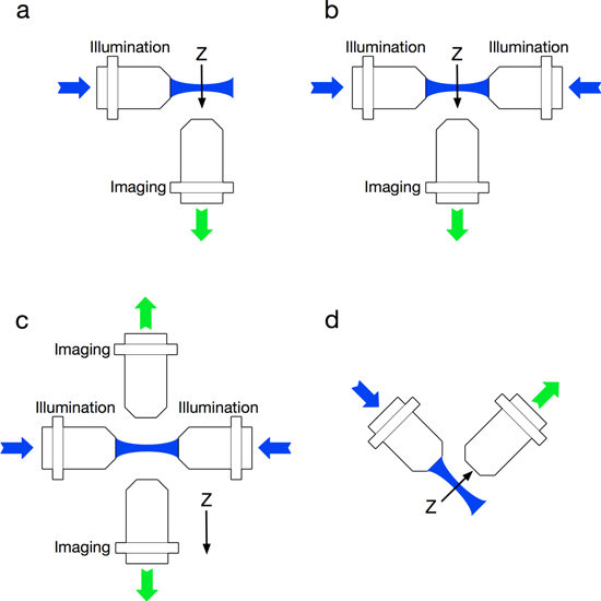
Figure 3. Standard LSFM configurations. (a) SPIM with a single illumination and orthogonal imaging arm, (b) mSPIM with bidirectional illumination, (c) MuVi-SPIM with bidirectional illumination and imaging and (d) iSPIM with a single illumination and orthogonal imaging arm but in an inverted position.
Download figure:
Standard image High-resolution image2.3. Open source systems and software
One unique feature with light sheet microscopy is the OpenSpim option which was probably the first truly open access high performance scientific instrument [42–44]. Although image processing software had been readily available as open access (ImageJ and Fiji), the complete plans for building a microscope had not been released in this manner. The associated website provides all of the component lists and assembly drawings required to build your own SPIM system. There are even the designs for 3D printing certain components including for example the sample holding system. This documentation has now been further supported by online videos that show people building a system and providing useful tips on how to obtain the best performance from the system. As well as enabling an advanced imaging method to be built at a reasonable cost, within a user's laboratory, it also provided a stimulation for a life scientist to develop collaborations with optical physicists and instrument builders. Although the assembly is not complex for an experienced optical instrument researcher, it is harder for those life scientists who had previously only used commercial microscopes. Thus, life scientists have spoken with optical experts within their research organisations to collaborate to build an OpenSpim system. These collaborations have frequently formed the focus of a final year undergraduate project but more importantly have opened up the potential for further interdisciplinary collaborations. Many of the papers outlined later are built on the OpenSpim chassis with novel optical improvements to solve challenges posed by specific life science investigations.
This model is only really viable when the control software is also released, and early versions were released linked with the Micromanager open source package with an option to run on an Arduino computer board if the user so desired [45]. Variations on this have also been developed and reviewed enabling more complex experiments to be undertaken [46]. In light sheet microscopy, many of the challenges really start once the system is ready to run and the data has to be captured. As one main feature of the technique is the speed and long term imaging potential of the system, datasets can become very large very quickly and generating greater than 2 Tb of data from a single imaging session (24 h) is not unusual. This means that new ways need to be considered at the start of any experiment, for both the post processing of the data [47], the storage and the normally simple task of taking the data from the laboratory to the computer on which you may do the image processing. Further details on the way this is handled in the OpenSpim configuration has been described [48] and simple 3D reconstruction is now implemented as Fiji plugin to correlate multiview 3D images [49]. The full challenges of the data processing are beyond the scope of this review paper, which focuses on the optical aspects of the method. To give an indication of the current routes being investigated, ClearVolume is an open-source package for live graphical processing unit (GPU)-accelerated 3D+t multichannel visualisation [50], specifically designed to deal with the large 3D and time data sets. As mentioned above, there are now multiple variations on the OpenSpim core instrument and these have been reviewed where their different features are compared (DIY-SPIM, OpenSPIM and OpenSPIN) [51].
3. Genetic manipulation and SPIM applications
Before considering the recent optical improvement being made in SPIM, it is important to appreciate the biological questions of interest and the associated biological innovations. Recent years have seen a number of such technological innovations, which are opening up totally new ways to study the development of complex multicellular organisms. Novel approaches to bio-imaging and automated computational image processing allow the design of truly quantitative studies in developmental biology. The challenge is to understand how an embryo's genes, proteins, and cells, function and interact to manage morphogenesis, cell fate specification, and patterning. With the new advances in biological imaging described above, it is possible to: track morphogenesis and mitotic lineages, visualise dynamic gene expression, cell signalling, optogenetic control, cell behaviour, cell fate choices, cell interactions during tissue growth. As they may be analysed in vivo for entire organisms and throughout embryonic development [52].
The use of genetically encoded fluorescent proteins changed the study of in vivo biology [10] enabling the transition from single organs to organisms, and from images of fixed, stained tissue sections to movies of in vivo embryogenesis. Actually, single cells, tissues, whole organs, and entire embryos can be specifically marked with genetically encoded proteins of various colours [53]. Once a protein is genetically identified, it can be manipulated in vivo or in vitro, so a specific cell produces these fluorescent molecules that can be identifiable through optical fluorescent imaging. Fluorescent markers can also be manipulated to attach to specific sites (organelle, membrane, nuclei) in the cell. In Vivo manipulation can be performed by breeding transgenic animals. The transgenic manipulation can occur in all the cell of the organism, or in specific sites, making use of organ-specific promoters, which involves protein over expression or protein knockout from within a short gene sequence. The transgenic manipulation can also be produced using drug-induced determination processes that can be either total or organ-specific.
Light sheet-based techniques are a powerful tool for live imaging of biological specimens, as they provide an exceptionally high imaging speed, high signal-to-noise ratio, low level of photo-bleaching and good optical penetration depth [54, 55]. This unique combination of capabilities makes light sheet-based microscopes highly suitable for live imaging applications, facilitating long-term observation of living biological processes. LSFM are particularly well suited for fast and long-term imaging of developmental processes at multiple spatial and temporal scales. Its application goes from imaging gene expression patterns and molecular interactions to the reconstructions of early developmental dynamics and in toto imaging of large fixed specimens [36, 56, 57].
Within only a few years, light sheet microscopy has contributed substantially to the emerging field of real-time developmental biology. High-speed multiview acquisition and low photo-toxicity have made SPIM a popular choice for studies of organ morphogenesis and function in zebrafish, Drosophila, and other model organisms. Applications include: from genetically encoded calcium indicator [58–61] allowing the acquisition of functional imaging [58, 60] and FRET process [61], to genetically modified embryos, expressing a variety of fluorescent proteins. As an example, the zebrafish [11] can be in vivo manipulated to create genetically modified families, as the transgenic lines (NpHR-mCherry), Tg(kdrl:GFP), Tg(myl7:DsRed), and Tg(myl7:GFP), all now commonly imaged using SPIM [62–66].
The variety of biological applications and the current diversity of light sheet-based techniques illustrate not only the growing popularity of the technique but also suggests a bright future ahead. LSFM has transform in vivo and intact organ imaging in a number of areas of biology, as it is much faster and gentler than other established fluorescence microscopy techniques [67]. Fundamental challenges for live imaging proves that SPIM is an indispensable tool for the in vivo long-term imaging of large developing organisms, as in zebrafish embryogenesis [68], and investigations of cellular and sub-cellular dynamic processes [69], as in cell division dynamics [70]. Driven by technical advancements, it is expected that more demanding biological questions awaken. Over the up and coming imaging performance of the microscope, we can expect powerful add-ons, for example, photo-activation [66], laser ablation [71], and fluorescence correlation spectroscopy [72], which will be discussed later. Biological research will look deeper into established and novel model organisms and, for the first time, will focus on rapid intracellular processes and morphogenetic movements of tissues during the course of hours [14].
4. Recent optical advances in SPIM
The liberty of controlling the illumination arm and the detection arm separately, has given researchers many ideas on how to adapt and change the original LSFM techniques [1, 4, 5] to fit specific needs predominantly in the excitation path. The major reason for this is that in terms of the detection there are few direct improvements that can be made beyond multiple cameras [35], higher performance cameras with specialised features such as the rolling shutter [34] and the use of adaptive optics to remove induced aberrations from the sample and system [40]. In the multidirectional illumination route, there are the mSPIM, MuVi-SPIM [36] and SIMView-SPIM [73], combining multiple illumination directions and multiple view directions to create a Multiview [35] image of the sample, and these modifications were discussed above. The next increase in complexity comes with IsoView [74] where, with the addition of extra optics and two more cameras, each arm can be used for illumination and detection sequentially or simultaneously.
The first major advance beyond those already described, which mainly consist of using multiple beams, was the introduction of structure encoded onto the beam pattern [75, 76]. In the first of these publications the conventional method of structured illumination was used implemented on the SPIM system using a digitally scanned light sheet, but in this configuration the excitation laser was passed through an acousto-optical tunable filter (AOTF) before being digitally scanned. The AOTF placed a sinusoidal intensity pattern onto the excitation light as it was scanned, such that the resulting time averaged intensity pattern for a single camera shot had a sinusoidal intensity pattern across the light sheet. In line with normal structured illumination, the phase of the pattern was altered at to give three images at 0, 2π/3 and 4π/3, and the sum of the squares of the difference of the images was calculated. This process meant that only light emanating from the combined focal plane of the light sheet and observing lens was visualised, removing the fluorescence generated out of focus, thus the scattered light. This enabled the imaging of Drosophila embryos for over 58 h at high contrast removing the scattering effects that had previously shrouded fine features. A variation to remove this scattered light used the HiLo method, also with intensity encoding [76] to increase the signal to noise in the focal region. All of these methods demonstrated successful results but do not seem to have been taken up as standard improvements by the majority of the SPIM community.
Having pondered on the use of intensity modulation on the beam, the other consideration was to increase the length over which the light sheet is narrow in effect to produce a larger field of view for each optical slice. This was achieved using a Bessel beam with scanning [77] which has an extended depth of focus but with the cost of redistributing some of the light intensity from the sheet to side lobes, which excite some fluorescence in either side of the main focal plane. Yet, this complication was then removed through the use of the same beam profile, but exploiting a near infrared ultra-short pulse excitation beam to produce two photon excitation [78]. The use of nonlinear methods meant that, when the Bessel beam profile is squared (the intensity profile that in effect excites the sample) the extra energy in the side lobes is reduced, compared to the main excitation central core of the beam. In this later setup, the team also added structure illumination to the beam to further remove the out of focus effects and improved the axial resolution to sub-micron dimensions for the first time. The samples used in this case were cultured cells and not intact whole animals and thus the macroscopic imaging capability of the SPIM system were not utilised, only the speed for optical sectioning and the reduced levels of bleaching. A subsequent paper described in detail how to implement this method in some detail [79], though the optical configuration is still complex and although can clearly be made to work, maintaining this in a standard biological imaging facility would be challenging. This technique was then taken one stage further by applying a two-dimensional lattice light sheet to enable super-resolution imaging [80]. Again, the results were predominantly from cell cultures or C. elegans at a very early (2 cell) stage of development. In this case, the high resolution and still reasonable speed enabled protein movements within the cell to be studied for the first time, and provided some stunning new images.
Building on the use of a more exotic beam profile, an Airy beam was then introduced [81], offering a simpler implementation into an OpenSpim instrument [82]. The challenge with such a beam format is that it has a curved beam profile with a number of areas of peak intensity, however, it also has the self-healing property of the Bessel beam and extended depth profile. Rather than use nonlinear excitation to remove the imaging artefacts introduced by these intensity lobes, deconvolution was applied to the images. This did clean up the images to provide some impressive datasets, but the full advantages of such a format have yet to be realised. Their true application may well be imaging very deeply within samples when the method may need to be combined with adaptive optics on the imaging arm of the microscope to remove the aberrations induced on the way out. The deconvolution method they use also assumes that the lobes are in exactly the position predicted, which could lead to spurious features on an image in some situations though this has not yet been shown.
Beyond the use of novel beam profiles, a number of other variations are associated with the sample positioning. The original SPIM configuration used a vertically mounted sample which works well for extended imaging of certain samples. However, this is not suitable for high throughput methods, nor for the use of light sheets in more conventional samples (as mounted for traditional microscopy methods). Thus, results have been reported on inverted and inclined SPIM setups, and dual direction inverted SPIM, as well as their variations, incorporating Raman, two-photon and fluorescence lifetime imaging. Novel methods of introducing the light sheet have also been developed, including the use of a mirror so that the illumination passes through the same objective, or just below it to produce the light sheet [83, 84] (a method employed by Leica as an add-on to a confocal to undertake light sheet microscopy).
In order to present the reader with a useful guide to all of these methods, they are summarised in table 1.
Table 1. List of the different fluorescence light-sheet techniques and their main features.
| Name of the technique | Principal feature | References |
|---|---|---|
| Classic technologies | ||
| Ultramicroscopy | First light sheet microscope, used a convergent beam of intense sunlight, and projected a slit through a colloidal sample | [3] |
| OPFOS | Orthogonal-plane fluorescence optical sectioning microscopy. Early version the light sheet fluorescent microscope, used a simple cylindrical lens | [4] |
| Confocal theta microscopy | Early version, used two objectives to separate the illumination and detection, the observed volume was spherical | [5, 6] |
| SPIM | Single or selective plane illumination microscope basic setup, put the technique at the scientific spotlight | [1] |
| OPTiSPIM | Integrating optical projection tomography in light sheet microscopy, by rotating the sample to collect 3D data | [27] |
| Scanned beam structure illumination techniques | ||
| DSLM | Digital scanned light-sheet microscopy, fast scan a laser beam to create a virtual light sheet | [31] |
| SPIM with SI | SPIM with structured light | [85] |
| DSLM-SI | DSLM with structured illumination | [75] |
| 3D HiLo SPIM | Additional structuring of the illumination (high and low frequencies) for improved background rejection | [76] |
| sTSLIM | Scanning thin-sheet laser imaging microscopy with SI and HiLo background rejection | [86] |
| Lattice sheet SPIM | Ultrathin light sheets derived from 2D optical lattices, using an SLM to create the lattice and dithered mode to excite the sample, and requires at least three raw images per reconstructed image | [80] |
| Exotic beams techniques | ||
| Bessel SPIM | Scanned Bessel beam plane illumination microscopy using different approaches | [79, 80, 87–91] |
| Airy SPIM | Scanned Airy beam plane illumination microscopy using different approaches | [81, 82, 92, 93] |
| Confocal and multiview techniques | ||
| Confocal SPIM | Confocal line detection, single or multiview | [34, 35] |
| diSPIM | Dual view inverted SPIM imaging, requires two raw images per reconstructed image, and deconvolution for a maximum resolution | [94, 95] |
| HR-OPFOS | High resolution OPFOS, by scanning an object through the focal zone a and recording only a few 1D pixel lines within this zone | [96] |
| mSPIM | Multidirectional SPIM, illuminates sample from both sides | [30] |
| MuVi-SPIM | Multiview SPIM, two detection and illumination objective lenses | [36] |
| IsoView SPIM | Each arm can be used for illumination and detection sequentially or simultaneously, giving four different views of the sample | [74] |
| SiMView SPIM | Simultaneous multiview, it is a MuVi-SPIM where both sides are simultaneously registered | [73] |
| triSPIM | Light sheet microscopy with isotropic super-resolution as three lenses are disposed in the 3-axis around the sample | [97] |
| ASLM | Axially swept light sheet microscopy, using a CMOS camera and a high NA remote focusing objective, scanning the sheet across the sample and registering just the focus region | [98] |
| DiaSLM | ASLM capable of translating a light-sheet arbitrarily in 3D | [99] |
| Inverted, inclined and single objective techniques | ||
| pi SPIM or πSPIM | Oblique light-sheet microscope with high NA, high resolution isotropic light-sheet imaging | [100] |
| Open-top SPIM | SPIM for conventional mounted specimens, lenses at the bottom, imaging at 45° through a water prim and cover glass | [101] |
| iSPIM | Inverted SPIM for direct imaging of a variety of samples. The lenses are positioned on top of the sample, as in a direct microscope, at 45° | [102, 103] |
| iSPIM-FCS | Inverted SPIM with fluorescence correlation spectroscopy (FCS) | [104] |
| HILO or iSPIM | Highly inclined and laminated optical sheet or inclined SPIM | [105, 106] |
| LSBM | Light-sheet Bayesian super-resolution microscopy, SPIM for super-resolution imaging using a prism-coupled condenser design | [107] |
| OPM | Optically sectioned imaging by oblique plane microscopy | [108] |
| RLSM | Reflected light-sheet microscopy, using a micro prism or mirror to reflect the light sheet | [109, 110] |
| SoSPIM | Single objective SPIM, uses a single objective with a miniature mirror inserted into the objective to redirect the light sheet | [83] |
| APOM | Axial plane optical microscopy, use only one objective to create the light-sheet and collect the fluorescence by optically rotating the imaging plane | [111] |
| SCAPE | Swept confocally-aligned planar excitation microscopy, use only one objective to create the light-sheet and collect the fluorescence by optically rotating both the imaging and illumination plane | [112] |
| Aberration correction techniques | ||
| WAO-SPIM or Adaptive SPIM | Imaging deep and clear in thick inhomogeneous samples with a wavefront sensor adaptive optics in the imaging arm of the SPIM | [37–41, 113, 114] |
| SPED- SPIM | Spherical-aberration-assisted extended depth-of-field light sheet microscopy | [115] |
| Nonlinear, super resolution and advanced techniques | ||
| 2P-SPIM | Combines two-photon imaging with the light-sheet microscope, as well as other technologies to increase resolution and quality | [90, 116–126] |
| Raman SPIM | SPIM integrated with Raman imaging | [127–129] |
| SPIM-FCS | Fluorescent correlation spectroscopy integrated into a SPIM system using a high speed EMCCD | [130, 131] |
| SPIM-FLIM | SPIM with fluorescence lifetime imaging microscopy (FLIM) | [132] |
| Hyperspectral SPIM | Scanned line SPIM with the detection of the line on a spectrometer | [133] |
| SPIDDM | Selective-plane illumination differential dynamic microscopy, SPIM combined the digital Fourier methods to provide the ensemble transport dynamics | [134] |
| SPIM with trapping | Integrate LSFM which solely uses optical forces to trap and hold the sample using a counter-propagating laser beam geometry | [135] |
| IML-SPIM | Individual molecule localisation SPIM, allowing live 3D super resolution microscopy | [136–138] |
| SMD-SPIM | SPIM for single molecule detection and tracking, using single molecule algorithms to analyse the images | [139–142] |
| SPIM-STED | SPIM with stimulated emission depletion | [143–146] |
| RESOLFT | Implements the reversible storable/switchable optical (fluorescence) transitions technique in a light sheet configuration for super-resolution imaging, with axial resolution enhancement | [147] |
In [8, 51, 148, 149], some of these different SPIM configurations are reviewed, including the exotic beams and two-photon methods. In [20], the advantages and disadvantages of some of these techniques are discussed, and in [84, 150] there are further insights on super-resolution and advanced LSFM techniques. For more information on the advanced and single-objective techniques, one can refer to [151], which review LSFM for multistage imaging.
5. Dynamic SPIM for extended time or rapid viewing of biological events
As illustrated above, one of the strengths of light sheet microscopy lies in both the speed and duration with which one can image and it is therefore the method of choice for non-invasive, temporal imaging of intact, fully functional organisms to study the dynamics involved in shaping complex organisms. In an example study, using a DSLM, the dynamics of Arabidopsis thaliana samples was investigated [152], in close to natural growth conditions, allowing imaging live plants at the structural, cellular and subcellular scales. The plant's growth was imaged for multiple days with no perceived damage or alteration to the sample, allowing the study of its cell differentiation and root development. In the case of plants, which clearly use light as part of their development processes, the excitation light for SPIM was only activate as an optical slice was obtained, thus minimising the effects of the imaging light on the growth of the plant. SPIM offers the best compromise between preserving conditions as close as possible to those natural to the sample, and allowing the observation of biological processes at the appropriate temporal and spatial resolution [12, 14].
This extended time imaging of SPIM, therefore, utilises the minimal light dose to the sample among the light sheet methods, however, this leads to a new challenge, to maintain the sample under physiological conditions. In the case of zebrafish imaging, mSPIM was used for long-term imaging [153] where growth and immobility defined the criteria for proper development, and spatial confinement, for precise imaging of the zebrafish embryo. The team used 3% methylcellulose or 0.1% agarose in an FEP tube to ensure proper growth and immobilisation. The other secret being to maximise the light collection in order to reduce the excitation intensity.
In analogy to using the extended imaging capability of SPIM, is to use its speed to capture an optical slice. This speed of image capture has been used in different ways to watch high-speed dynamic processes, as for example, to monitor the movement of the beating heart in the zebrafish. In one approach, a conventional near infrared transmission image is taken on a camera at around 100 frames s−1 and analysed in real-time for the movement pattern of the heart. After a few cycles the system is capable of predicting when the heart will be in a certain position in its cycle, and this predication is used to activate the light sheet and camera to record an optical slice at a particular point in the heart cycle [154]. Based upon this, a dynamic image of the beating heart can then be recorded of movement in three dimensions. An example of the images such a method can obtain is showed in figure 4, presenting the zebrafish heart in different configurations [155]. An alternative approach is to record multiple images at high speed and then to use post processing to assemble the movement by looking for similarities within images at different time points [156]. In this latter publication, a new insight into the role of certain proteins in the sheer stress within the heart was provided.

Figure 4. Dynamic image of the beating heart. LSFM images of the zebrafish heart, at different positions in the beating cycle. (a) Fluorescent images of the heart at different point in the beating cycle, and (b) 3D rendering of the zebrafish heart at different points in the beating cycle. Reproduced with permission from [155].
Download figure:
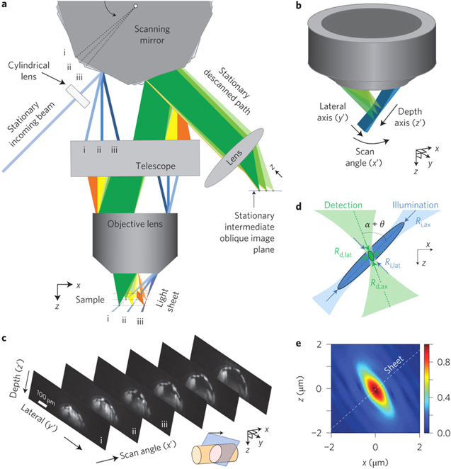
Standard image High-resolution imageThe other area of high-speed imaging is to create rapid three-dimensional data sets. Using a conventional SPIM system, though with dual excitation and collection, it has been possible to image at a rate of 200 frames s−1 [78]. This lead to a 50 slice volume taking around 0.5 s to record. However, this turned to a significant challenge, when imaging the neural wiring during C. elegans development for 5 h period [95], of vast quantities of data. Crucial to the biological relevance in this was the low photoxicity of the SPIM method. At present, the highest recorded speed for volumetric imaging is through a variation of the SPIM method, in a system known as SCAPE [112]. Figure 5 illustrates the key optical concepts in the SCAPE method which achieved imaging at rates up to 200 volumes per second and was used to study signalling within the mouse brain. This method uses a single objective and the light sheet is scanned through the lens at an angle using a polygon mirror. The objective collects the fluorescence light, which is then reflected onto the camera by an adjacent element on the polygon array. This has the effect of sweeping the light sheet rapidly through the volume of the sample with only the rotation of the mirror. The method was also demonstrated in the same publication in Drosophila, to observe the beating heart.
Figure 5. Swept confocally-aligned planar excitation (SCAPE) microscopy from Bouchard et al 2015 [112]. Reprinted by permission from Macmillan Publishers Ltd: [Nature Photonics] [112], Copyright (2015).
Download figure:
Standard image High-resolution image
6. Advanced SPIM: nonlinear and super-resolution techniques
As mentioned before, the main advantages of LSFM are related to its optical sectioning, high contrast, high imaging speed, and low phototoxicity [17], but every technology has its drawbacks [149, 157]. Because of its inherent flexibility, light sheet microscopy can be adapted to overcome specific challenges in many different configurations, as it is a mesoscopic method that uses an engineered light sheet, of finite thickness, to excite fluorophores within its volume. Although, it is the least invasive, in terms of excitation light intensity, compared to other routine microscopy methods, and allows near-physiological monitoring of intracellular dynamics at very fast rates and for a prolonged imaging period, its resolution is not as high as some methods, in effect, trading speed for resolution. But LSFM is such a versatile technology that it can be combined with other techniques to overcome these resolutions limitations, such as two-photon imaging, structured illumination or STED to reach super-resolution levels. These methods have then been linked with other detection methods, such as Raman, to obtain multispectral images [158] at high resolution, though generally at the expensive of temporal resolution.
One of the first moves for improved resolution, and an increase in the potential depth at which samples can be imaged, was the use of nonlinear excitation. In conventional beam scanned nonlinear microscopy this typically leads to a loss of resolution compared to single photon excitation due to the longer wavelength increasing diffraction effects. However, in the case of SPIM the nonlinear effect can be used as an advantage, reducing the volume in which the light intensity is high enough to stimulate excitation. Development of the light-sheet excited multiphoton fluorescence microscopy has now been reported by several research groups [90, 116–126, 137]. These instruments frequently combine other techniques to increase resolution and quality, such as incorporating Bessel beams and structured illumination as well as using second harmonic generated images. Other technologies that have already be integrated into SPIM are Raman imaging [127–129], fluorescent correlation spectroscopy [130], fluorescence lifetime imaging microscopy [132], and spectral imaging [133]. These multimodal systems represent an optimal platform for tissue imaging and they are further increasing the applicability of light sheet microscopy to a wider range of samples, including those that have to be mounted on non-transparent surfaces.
The next obvious direction for LSFM was to follow the path into super-resolution imaging, yet clearly recognising, again, that the potential for high-speed imaging was being traded-off against resolution. The first advance here was through the various methods of imposing a light intensity pattern on the excitation beam which was subsequently followed by a more direct implementation of the structured illumination method [75, 85]. Although the method led to an improvement in resolution, the main benefit was a reduction in signal from scattered light, leading to enhanced contrast images. This work was then followed by true super-resolution imaging in a LSFM using the PALM technique [136, 138]. In this work two light beams were used, one to activate a reduced set of the fluorescent molecules within the sample and subsequently to de-activate and then activate a separate set. To this date, this method has only been used in tumour spheroids to a depth of around 150 µm and not in more intact samples. The stochastic super-resolution method, STORM, was combined with SPIM in 2015 to a yeast based sample [139]. Further variations on these methods, all using localisation algorithms to determine a single molecule's position have since been implemented [136–142] in a broader range of samples.
Light sheet implementation of STED was achieved in 2011, followed again by variations in the method [143–146]. The original version is worthy of specific mention, as they used a dye that emitted in the near infrared, as scattering was a potential confounding issue and the longer wavelength helped to reduce this effect. The aim was to increase the resolution along the imaging optical axis, and a light sheet was created with a laser around 640 nm and this sheet was surrounded by a sheet shaped for depletion beam, with a hole through the middle (in effect very elongated ellipse with a central hole) created using a TEM01 beam profile sent through the cylindrical lens in a conventional SPIM system. This gave a 60% improvement in their axial resolution. In another variation of the method, and perhaps closer to the PALM technique, RESOLFT (reversible saturable/switchable optical fluorescence transitions) has been implemented in a light sheet configuration [147]. Here, rather than causing stimulated emission to remove the excited molecules, photoactivatable molecules are switched off such that only a thin sheet of molecules is available for excitation by the light sheet. Once sufficient photons have been gathered for one very thin section the next layer can be prepared with, again, only a thin sheet of molecules being allowed to enter the fluorescent emission state.
In an alternative method, rather than removing the emission or preventing the excitation of molecules, the volume in which they were created was minimised in the so called lattice sheet microscope [80]. The full details on how this was achieved can be found in the publication, but in simple terms, through the interferences of light patterns, it is possible to create a light sheet consisting of multiple point in space and by dithering these spots around, it is possible to fill an optical plane to take a slice where each excited pixel is very small. Using this method, it was possible to image at high frame rates though some level of post processing is required. To date, this is the highest speed, super-resolution method that has been developed, however, full implementation is not trivial, both optically and computationally. A review of the super-resolution methods and specifically their application to plants can be found in [159].
7. Some selection considerations
As is clear from the text above, the number of light sheet microscope options is now enormous, with each method having its own specific application, advantages and drawbacks. In this section, we will try and provide some guidance to the reader on the considerations that should be made before selecting a particular method. As with all imaging tasks, the final selection is certain to involve some form of compromise between competing parameters, such as resolution, speed, field of view, ease-of-use and perhaps, in the end, cost.
Before discussing the selection of a specific light sheet method, it is worth recapping briefly on why you might consider using this approach in preference to other three-dimensional imaging methods. One clearly needs a sample that is generally transparent, not too highly scattering and has three-dimensional structure. The major advantages of the light sheet method are the ability to record optical slices rapidly with high, but generally not super, resolution. The images are normally recorded with lower levels of phototoxicity and photobleaching than alternative three-dimensional methods and this makes extended imaging of live samples more viable. With the advent of the OpenSPIM options, it is also the lowest cost three-dimensional imaging modality.
The first consideration is the main configuration of the light sheet that one wishes to use and this is entirely determined by the sample. The conventional light sheet, with the optics in the plane of the table, requires the sample to be suspended in centre of the instrument in a clear material. Although this is the most common light sheet configuration, the challenges in mounting the sample should not be overlooked. For zebrafish, plants and organoids mounting inside agar or FEP tubing works well and provides access to all of the major areas within the sample. C. elgans can also be imaged in this manner but are perhaps more amenable to horizontal sample mounting. Referring to table 1, this is the case of configurations based on the classic technologies configuration, as is the case of SPIM and DSLM. Optically, the conventional configuration is the easiest system to build but is not the best system for high-throughput imaging, as each sample has to be individually prepared. If the sample is not highly fluorescent, then adding a second imaging camera and light beam to increase the light intensity is most easily achieved in the conventional configuration. The second light sheet is also useful for imaging more deeply in samples, or samples where excitation light can be lost before reaching the target organs of interest.
The inverted and inclined configurations require greater engineering skills to bring the optics out of the plane of the table, as they are often perpendicular. This configuration does enable the sample to be laid down in the focal volume and thus the sample could be in microfluidic channels and moved more rapidly under the imaging instrument. Most of the inverted, incline or single objective techniques allow the sample to be placed on top of microscope slides, as is the case of iSPIM, open-top SPIM and SCAPE referred in table 1. The inverted configuration is perhaps better for brain imaging in a range of samples, including rodents, and thus if this is the main imaging target, the extra complication of the inverted method is worth considering.
Having decided on the configuration, now one has to consider the resolution and field of view required. Many systems, including the ones built by the authors, use a x10, 0.3 NA excitation objective and a x16, 0.8 NA imaging objective. This, in theory, provides a field of view of around 1.5 mm. However, it is not possible to produce a uniform, thin light sheet over this volume, unless a Bessel beam is utilised (with the other complications of side lobes which need to be removed, normally by post processing) or other advanced techniques as ASLM. For a light sheet of 2 µm thickness, one typically has a field of view of around 150 µm. When the thickness of the light sheet is convolved with the point spread function of the imaging objective, this gives an axial resolution of around 1.5 µm before any post processing is undertaken. For high axial resolution, one can make the light sheet thinner but the region over which it is thin and uniform decreases rapidly.
The highest lateral resolution that one can achieve is limited by the imaging objective NA and is around 0.4–0.5 µm. To achieve this performance, one requires a camera with sufficient pixels of the correct size for Nyquist sampling of the field of view. For example, for 0.5 µm resolution and 16 times magnification, one would require pixels of around 4 µm for Nyquist sampling. These criteria are now easily reached using modern sCMOS cameras. Again, one can increase the field of view, by adjusting the tube lens before the camera, which alters the effective magnification but will then no longer be Nyquist sampled and this can introduce distortions in the image.
The next decision is likely to be on the speed and volume that one wishes to image. Higher speed is probably best achieved at present, either using the SCAPE configuration, or the use of two cameras, one from each direction, and two light beams synchronised so that while one camera is imaging, the other is transferring its previous frame, as in MuVi-SPIM. It should be remembered that in high speed imaging, one does need a bright sample and that the signal to noise will become worse, but this is the expense that has to be paid for the speed. It is likely that the volume imaged will decrease, again so that the region imaged is seen multiple times per second. When imaging at high speed, it is also vital that the data handling is considered at the outset, both in terms of storing the data and also subsequent processing.
In the foregoing text, we have also described multiple other features that have been developed to overcome imaging challenges. Should these be employed on a routine basis? The use of the scanned light sheet is useful in samples where there are absorbing features present before the area of interest. This method does remove 'streaks' in the image and should probably be considered for most samples. Dual direction illumination also helps with this issue, though adds significantly to the complexity of alignment. In samples that are more highly scattering, and when imaging more deeply, then the use of the scanned light beam combined with the rolling shutter to produce effectively a line scanned confocal system is a very powerful option, such in confocal SPIM. Again, this requires greater instrumentation expertise but the removal of scattered light from the image can significantly improve the signal to noise. The exact gain though is clearly sample dependent.
The final areas, and the point at which the cost of systems significantly increase, is in the use of nonlinear excitation and super-resolution. Both are more technically challenging and are probably only required for specific imaging applications. Nonlinear excitation does enable deeper imaging, but unlike beam scanned nonlinear microscopy, where all fluorescent photons can be collected as they can only have come from a single volume in the sample, scattering of the fluorescent light as it emerges through the sample limits nonlinear methods usefulness. The combination of the rolling shutter and nonlinear excitation can help to mitigate scattering on the output but one is now rejecting precious signal photons. Super-resolution, using either structured illumination or STORM/PALM options, should only be considered when the extra resolution is really required to understand the biology taking place. One generally loses speed and the low photobleaching advantages of SPIM and thus perhaps the advantages are out-weighed by these losses.
8. Future directions and summary
As can be seen from the previous sections, light sheet microscopy has made huge advances in the last few years, since its original inception, and this has been strongly influenced by advances in technology, both optically and biologically. The question then has to be asked: what might come next? Presently, within the field of Biophotonics, the term 'optogenetics' is being used widely, and the main application area has been in the field of neuroscience. Where by genetically encoding a protein, which can be 'switched on' or 'off', the reactions of a live animal can be altered by using light. This means that specific neural pathways can be activated and studied in isolation and light sheet microscopy, as mentioned in numerous places earlier, is now becoming one of the methods for studying brain activity with its ability for high-speed 3D imaging [112]. Another variation on this is the use of light to specifically kill cells that are expressing the 'KillerRed' protein [160]. Here, when exposed to light around 561 nm the cells expressing the protein die due to the production of reactive oxygen species during the fluorescence process. In previous works, this transfection and subsequent cell death was only undertaken in cell based studies. However, using the SPIM configuration, with the 'KillerRed' being expressed in the kidney's renin producing cells, live zebrafish were treated with a high survival rate, but presenting changes in physiology due to the loss of these cells [161]. The team used both the SPIM sheet to excite a larger number of cells, or a Bessel beam introduced through the imaging arm. Use of conventional optical microscopes led to high death rates in the fish. This was not the first time that a SPIM configuration had been used for what might be described as 'three-dimensional laser microsurgery' [71], where direct ablation of cells was achieved or local photo-activation of cells was undertaken [66].
A further area of direct biological application of SPIM is towards the use of three-dimensional cell clusters or, more especially, organs extracted from deep within an animal. Within the SPIM system, it has been shown that is it possible to keep entire organs alive for extended periods of time, and to use the light sheet to study cell interactions. This is likely to have a specific role to play in the field of immunology, where the organs are frequently hard to access using conventional methods, but where the intact organ continues to function for some time outside the animal [162]. Thus, as well as the continued imaging of entire samples, such as zebrafish and Drosophila, the imaging of intact, normally deep seated organs is likely to be an area of growing interest. The other area being explored by several groups is the use of SPIM, typically the inverted configuration, for high throughput screening and commercial systems are looking to use a micro-fluidic system to direct the samples, typically zebrafish, through the SPIM imagining volume [163, 164], or to perform cell cytometry [165].
In terms of the optical developments in light sheet based imaging, the drive is likely to continue to been in two directions. The first is for increased speed, and the SCAPE system, described above, is currently the leading implementation of this method. There will eventually be a limit on the speed as insufficient photons will be available for high quality imaging, but at the moment, the bottleneck is in the transfer of the images from the camera, although frame-rates are rising rapidly. The other area is likely to be improved resolution and contrast. As described, a wide variety of beam configurations have been used, including complex lattices of light. These have improved both the imaging contrast and spatial resolution, but typically at the expense of imaging speed. As the move is towards ever deeper imaging, in more mature samples, the further application of adaptive optics is likely to be important. Their use on the imaging arm has already been described [40], and it has been shown that they can be used to optimise an excitation beam profile [113], spatial adjustment of the excitation beam to directly overcome sample induced aberrations in the excitation beam path has only been recently reported [114]. An alternative approach is also to build the light sheet system on the end of an optical fibre, for in vivo invasive light-sheet microscopy at the tip of a needle [166]. It is likely that this regime of in depth imaging will be an area of technical advance in the near future. As more life-scientists really appreciate what light sheet imaging is capable of, then, it will be applied to an ever-increasing range of samples which are likely to require some novel optical solution to achieve the results required to answer increasing complex 4D challenges.
Computers and data processing also play a growing role in the field, as all imaging methods and protocols are already being developed to improve the apparent resolution and contrast within images [167]. However, one area that is only just being considered, however all builders and users of SPIM instruments were well aware of, is the challenge presented by the very large datasets that can be generated. Although all scientists are currently driven to store, and subsequently make available, their raw data before any manipulation or analysis is undertaken, this situation may need to change. With single data sets for a time lapsed imaging session, it is easy to take 3–4 Tb, therefore the storage requirements are becoming excessive and perhaps only processed data sets may be stored in the future. The different computational steps used in all imaging are now being quantified and examined in detail, and the inherent challenges and the overall status of available software for bioimage informatics, focusing on open-source options is now an important topic [168] and protocols and software for data management, processing and analysis [169] and data processing [170] are being discussed. To achieve the maximum benefit from this work, the data processing aspects must be considered alongside the optical advances in a truly integrated manner.
Since its reinvention, light sheet microscopy has advanced hugely in terms of the quality, range of samples imaged and speed of image capture. What is now routine would have been totally unbelievable to the original inventors over a hundred years ago. The light sheet and associated optics is the latest method, revolutionising the understanding of complex biological processes, crucially bringing both high resolution, three-dimensional imaging and speed, so that dynamic processes can be studied and understood in detail. This has been brought about over the integrated work between optical physicists, instrument builders, commercial technology suppliers, and the end users and the OpenSPIM model of releasing full designs of working systems that can be built at low cost from commercial components is a very interesting model. Indeed, the OpenSPIM route may become more common in the future as a result of its success and also as it becomes easier to purchase and combine high performance optics and computer controlled cameras and positioning equipment. Light sheet microscopy is now really starting to answer complex questions that previously could not even be considered, including how we all think and live.
Acknowledgments
The authors would like to acknowledge the support of multiple colleagues who have helped them within the field of light sheet microscopy, specifically Dr Laura Young, Dr Chris Saunter, Dr Miguel Jarrin and Prof Roy Quinlan in Durham University, Dr Charlotte Buckley, Dr Sebastian Rider and Prof John Mullins at Edinburgh University and Dr Jonny Taylor now at Glasgow University. Funding supporting this work has come from the Engineering and Physical Sciences Research Council in the UK, British Heart Foundation, Wellcome Trust, Leverhulme Trust and the Brazilian agencies, CNPq and CAPES.