
Abstract
Copper iron sulfide (CFS) (chalcopyrite) thin-film electrodes have been synthesized for energy storage applications using the SILAR method without the use of a binder. The film's structural as well as the morphological and electrochemical characteristics were studied to check the effect of varying deposition cycles. The x-ray diffraction (XRD) test reveals a crystalline tetragonal CuFeS2 (chalcopyrite) with a decreasing peak as the deposition cycle progresses. The micrographs of the films reveal a spherical but fleecy-like shape with particle aggregation at higher deposition cycles. The bandgap increased slightly towards higher cycles and is in the range of 1.15 to 1.22 eV. The CFS electrodes were evaluated in a three-electrode arrangement for supercapacitive application in a 2.0 M KOH electrolyte. The CFS electrodes function admirably. The greatest specific capacitance recorded was 537 F g−1 at 10 mV s−1 with capacitance retention of 93.5%. This is for CFS electrode deposited at 10 cycles; hence it has the greatest performance. This paper describes a simple, inexpensive, and repeatable method for fabricating electrodes for supercapacitors.
Export citation and abstract BibTeX RIS

Original content from this work may be used under the terms of the Creative Commons Attribution 4.0 licence. Any further distribution of this work must maintain attribution to the author(s) and the title of the work, journal citation and DOI.
1. Introduction
Global energy demand has risen rapidly as a result of the rising human population and the desire for equivalent improvements in living standards. Electrical energy has become crucial in every part of daily life due to the rapid increase in human energy-based activities. That is to say, energy is required for the majority of human activities nowadays. Photovoltaic power generating is the most environmentally friendly of all energy generation technologies. It is the most secure, dependable, accessible, and available option free of pollution.
Photovoltaic power generation cannot be efficient without an efficient storage device. The intermittency nature of photovoltaic power generation necessitates the storage of generated energy for round-the-clock use prompting the use of batteries and supercapacitors [1].
Though the use of batteries has been rampant for a long time, there are a lot of flaws with the use of batteries ranging from low power density to heating leading to fire outbursts [2]. Due to the fast and flexible charge/discharge rate, eco-friendly nature and ultra-high power density, the supercapacitor has gained ground for use in energy storage [3]. The structure of a supercapacitor mainly consists of a cathode, anode and a sandwiched separator [4]. The efficiency of the electrode material to a greater extent determines the overall performance of the supercapacitor [5].
Commonly, carbon-based materials considering their outstanding ultra-high power density and stability are prevalent but they suffer from relatively low energy density which limits their use in handy consumer electronics [6]. Also, polymers like polyaniline (PANI) possess exceptional electrochemical properties favouring their use as electrode materials but they lack greatly cycling stability as well [6].
Attention has been given to transition metal oxides (TMOs) considering their unique properties but their characteristic low electrical conductivity and low capability among other flaws became an issue prompting researchers to start exploring some other electrode materials that could be stable, eco-friendly, electrically conductive among key features required of good electrode material. Having noted that sulfur is more electronegative than oxygen [7], replacing oxygen and forming compounds with improved ionic diffusivity is a boom in electrochemical activities; researchers are attracted to transition metal sulfides (TMSs) [8]. Aside from the higher electrical conductivity of sulfides, they are cheap and possess better electrochemical performance than their oxide counterparts [3].
Of all the naturally occurring minerals on earth, chalcopyrite (CuFeS2) is more numerous and greatly exploited for copper recovery [4]. CuFeS2 is a member of the I-III-VI family of elements [8]. It has a tetragonal structure. Cu and Fe ions are in tetrahedral matching together with sulfur in the framework [9]. Because of their low toxicity and abundance in nature, researchers are interested in studying them. CuFeS2 is a typical n-type semiconductor. It has a relatively narrow bandgap [5]. CuFeS2 is a good solar cell material because of its excellent photoelectric and magnetic characteristics.
Though CuFeS2 has been studied in the laboratory by some scientists before now, its potential for energy storage is understudied. The application of CuFeS2 in the hybrid solar cells has been reported by Layek et al [10]. The use of CuFeS2 in lithium-ion battery and bed flow cell battery respectively by Guo et al [2], Ding et al, [6] and Deen et al [11]. Sahoo et al [12] got a specific capacitance of 98.2 F g−1 in the electrochemical performance of CuFeS2 in symmetric supercapacitor design in LiOH electrolyte. The lower capacitance reported by Sahoo et al could be as a result of the binder used in the fabrication of the electrodes which posed to add great electrical resistance hindering the electrochemical performance. The improved specific capacitance of 621.20 F g−1 for CuFeS2/grapheme composite electrode was reported recently by Zardkhoshoui et al [13]. The reason could not be far from the high surface area provided by the graphene for effective redox activity. Many researchers have reported on the solution-based synthesis of CuFeS2 like solvothermal [14] hot injection method [15], hydrothermal [16], one-pot method [17], and chemical bath [18]. Lokhande et al [7] employed a single-step hydrothermal method without a binder for CuFeS2 synthesis and got a specific capacitance of 667 F g−1. The use of binder and intricate processing of CuFeS2/graphene composite electrode results in high costs and lower performance. We chose the SILAR method because it is cheap, simple and environmentally friendly for effective performance.
Binders give active materials in which they are utilized mechanical characteristics [8]. The main ingredient is combined with the binder to generate a slurry that is applied at a specified thickness when using the binder. The thin, porous electrode is then formed by drying the slurry-coated substrate. Binders are commonly employed in electrodes to help them maintain stability beyond 5,000 charge/discharge cycles [15]. Binders have been observed to alter and reduce capacitance due to increased oppositions it imposes on the electrodes [3]. In this study, our synthesized electrodes are all fabricated without a binder and in keeping with current research on binder-free electrodes.
2. Materials and method
2.1. Materials
The chemicals utilized to make CuFeS2 thin films were analytical grade and had not been refined before use. Copper chloride dehydrate (CuCl2.2H2O), iron chloride tetrahydrate (FeCl2.4H2O), sodium sulfide (Na2S), and Triethanolamine (TEA) were utilized to make CuFeS2 thin films, with distilled water used throughout.
2.2. CuFeS2 thin film synthesis
1.0 × 5.0 cm sizes of stainless steel, polished with zero grade polish paper, sonicated with the glass slides for 15 min in acetone and 15 min in distilled water at 30 °C, and rinsed with distilled water before being dried in the oven. 0. 5 g of CuCl2.2H2O and 0.3 g of FeCl2 were dissolved in 100 ml distilled water, then stirred for 15 min. The cationic bath was maintained at pH 4 by adding 1.0 ml of TEA drop by drop under steady stirring for another 15 min. Separately, 0.8 g Na2S was mixed in 100 ml distilled water and agitated for 15 min before being utilized as an anionic bath with a pH of 11. The treated stainless steel and glass were each inserted into the bath containing cations for 30 seconds. Cu2+ and Fe2+, present in the bath are adsorbed on the substrates' surfaces. Cu2+/and Fe2+ ions that were not well adsorbed were washed for 10 seconds in distilled water. The Cu2+/Fe2+ carrying substrates were then submerged in a Na2S bath for sulfur adsorption on the substrates for 30 seconds. The anions which were not well adsorbed were washed off for 10 seconds in distilled water. The process was continued until ten, twenty, thirty, and forty cycles had been accomplished. The deposition process is depicted schematically in figure 1.
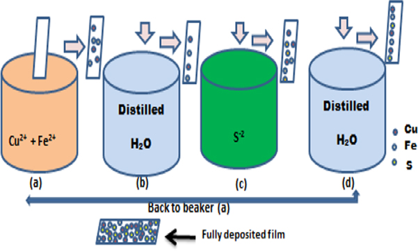
Figure 1. The SILAR process of depositing CuFeS2 is depicted schematically.
Download figure:
Standard image High-resolution imageThe samples are labelled CFS 1, CFS 2, CFS 3 and CFS 4 for sampled deposited at 10, 20, 30 and 40 cycles.
2.3. Characterization
X-ray diffraction (XRD) was used to characterize the structure and phase of CuFeS2 thin films (Bruker AXS D8 diffractometer coupled with copper anode at 1.540A). The morphology of the films was examined using a KFU-Sci machine with a voltage of 15.0 kV for scanning electron microscopy, and the optical characteristics of the CuFeS2 thin films were determined using a 756S UV-Vis spectrophotometer.
2.4. Electrochemical studies of CuFeS2 thin films
BioLogic Potentiostat was used to examine the electrochemical characteristics of CuFeS2 thin films. The studies were done in a three-electrode configuration. The electrolyte used was 2.0 M of KOH at a temperature of 303 K. The working electrode was the as-synthesized thin-film electrodes, the working electrode is the Ag/AgCl and the counter electrode is the graphite. The capability of CuFeS2 thin-film electrodes was tested in the 0 to 1.3 V potential range. The electrochemical test employed was cyclic voltammetry (CV), galvanostatic charge-discharge (GCD), and electrochemical impedance spectroscopy (EIS).
The specific capacitance of electrodes was determined from CV according to using equation (2) [9],

where CT is

 = integration of the CV curve area,
  = scan rate, and
  = potential used.
The specific capacitance of the CuFeS2 thin-film electrodes was also calculated from the GCD profile using equation (3),

where I = current, m = mass (mg),  = potential, and
  = time of discharge.
3. Results and discussions
3.1. X-ray diffraction studies
The XRD patterns of produced CuFeS2 thin films placed on glass substrates at 10–40 cycles are shown in figure 2. The reflection peaks at 29.4°, 48.7 °, and 58.7o corresponding to (112), (220) and (303) planes. The peaks correspond to tetragonal structure (space group: I-42d) with a lattice constant of 5.2864 Å (JCPDS no: 83–0983). There were no other diffraction peaks as seen in figure 2 indicating the purity of the CuFeS2 thin films.
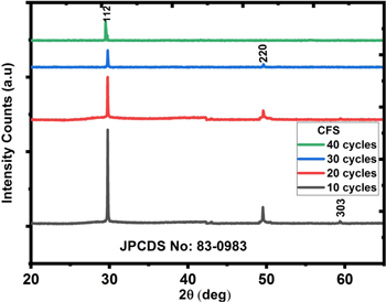
Figure 2. Graph of intensity against 2 for CuFeS2 depositions lasting 10 to 40 cycles.
Download figure:
Standard image High-resolution imageThe average crystallite of the CuFeS2 thin films was calculated using Debyer-Scherrer's formula (equation (7))

where  = wavelength,
  = full width at half maximum (in radians) and
  = the angle of diffraction. The most intense peak (112) was used to determine the FWHM. The average crystallite sizes of 16.4 nm, 16.96 nm, 17.12 nm, and 18.07 nm correspond to CuFeS2 thin films at deposition cycles 10–40, respectively. A close look at the XRD pattern shows that the increase in deposition cycles relatively dropped the peaks. This could be due to the size growth as the number of deposition cycles increases. The result is consistent with the findings of [16, 19–21].
3.2. Morphological and elemental studies
Figure 3 depicts the surface morphologies of the CFS films. The films were rather spherical and densely spread on the substrate, according to SEM micrographs. The micrograph of the CFS 1 film revealed a spherical but fleecy-like shape with particle aggregation at higher deposition cycles as in CFS 2 and CFS 3, and eventually, an irregular platelet-like nanostructure in CFS 4. The platelets have irregular thicknesses and a narrow gap between them. This narrow gap lessens pores and limits ions intercalation for redox reactions [7], hence the low capacitance of CFS 4. The fleecy-like nature and smaller particle size of CFS 1 encourage easy ion intercalation for faster redox reactions and hence an appreciably high capacitance measured. The measured average particle sizes using Image J software are approximately 35.5 nm, 51.7 nm, 54.9 nm and 83.3 nm for CFS 1, CFS 2, CFS 3 and CFS 4 respectively. The bigger particles came from crystallite aggregation.

Figure 3. SEM micrograph of CFS films.
Download figure:
Standard image High-resolution imageEnergy dispersive x-ray spectroscopy gave the elemental composition of the CFS thin films. Figure 4 indicates that our film contains Copper, Iron, and Sulfur, in the atomic percentage ratios of 1:1:2. Also found in the spectrum were Sodium and Calcium peaks from the used glass substrate and Oxygen from water used in the synthesis.
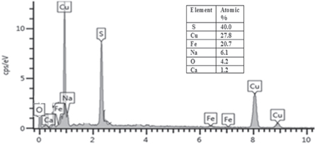
Figure 4. EDS of CuFeS2 films.
Download figure:
Standard image High-resolution image3.3. Optical studies
From the photon energy extrapolation in figure 5(a), the bandgap energy of the range 1.08–1.22 eV were recorded for CFS1 - CFS4. The narrow bandgap of the films complements the small particle size and favours photovoltaic applications, while their unique small bandgap boosts electrical conductivity and is a bonus in enhancing electrochemical performance. The range of values for electrical conductivity against wavelength ranged between 6.9 ×10⁻³–6.3 ×10⁻³ Sm−1 for CFS 1—CFS 4 within the Vis region as shown in figure 5(b). According to Teranishi and Sato [16], it diminishes as the wavelength increases. The CFS films have a high electrical conductivity that decreases as the deposition cycle increases.
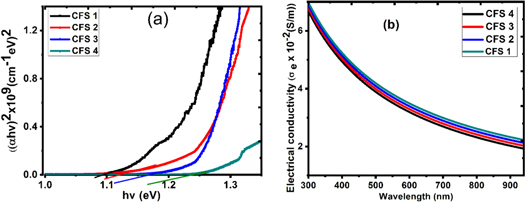
Figure 5. (a) (αhυ)2 against Photon Energy (eV) and (b) Electrical conductivity against wavelength for CuFeS2.
Download figure:
Standard image High-resolution image3.4. Electrochemical studies
The CuFeS2 electrodes' CV profile is shown in figure 6. The CV profile shows few redox peaks, signifying that the CuFeS2 electrode's capacitance is largely driven by a faradaic mechanism. The invariance in the redox peaks even at a scan rate of 100 mV s−1 implies that the CuFeS2 electrodes have good rate capability [12]. The shape of the CV profile is 'Type B' CV profile as suggested by [22] categorically. The calculated specific capacitance recorded at 10 mV s−1 for CFS 1, CFS 2, CFS 3, and CFS 4 is 584.2, 493.4, 279.7 and 139.8 F g−1 respectively using equation (2). The increase in specific capacitance is inversely proportional to scan rate because, at a higher scan rate, there is restricted movement of the electrolyte ions. The trend with which the specific capacitance varies with the scan rate is shown in figure 8(c).
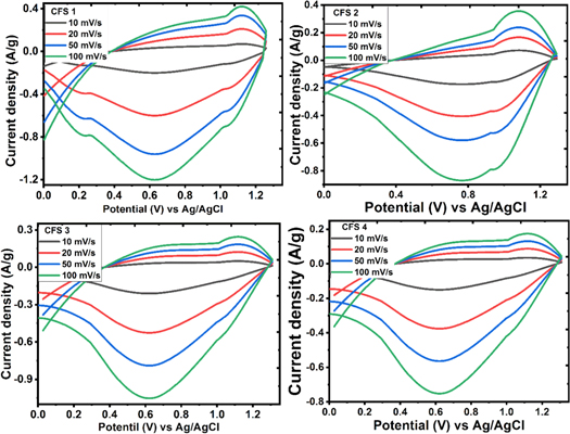
Figure 6. Cyclic voltammetry profile of CFS 1 to CFS 4 electrodes at various scan rates.
Download figure:
Standard image High-resolution imageThe Cs obtained for the electrodes is considerably higher than the previous reports of Deen et al [23], Sahoo et al [12], Zardkhoshoui et al [13]and slightly lower than the report of Lohkande et al [9] as shown in table 1. Table 1 shows the summary of specific capacitance (using three-electrode configuration) of CuFeS2 and some copper-based electrode materials.
Table 1. Summary of specific capacitance (using three-electrode configuration) of CuFeS2 and some copper-based electrode materials at 10 mV s−1.
| S/N | Compound | Method of preparation | Specific capacitance (F g−1) | References |
|---|---|---|---|---|
| 1 | CuFeS2 | hydrothermal | 95.28 | [12] |
| 2 | CuFeS2 | solvothermal | 654.3 | [13] |
| 3 | CuFeS2 | hydrothermal | 667.0 | [9] |
| 4 | CuFeS2 | green synthesis | 501.4 | [3] |
| 5 | CuS | sonochemical | 62.77 | [24] |
| 6 | CuSbS2 | colloidal | 34.0 | [25] |
| 7 | CuSbSSe | colloidal | 15.0 | [21] |
| 8 | Cu3SbS4 | hydrothermal | 60.0 | [26] |
The CD measurements were also carried out at current densities 1.0 A/g—3.0 A/g shown in figure 7. The analysis was done in the potential window of 0 to 1.4 V as depicted in figure 6. The nonlinear nature of the CD profile of CuFeS2 confirms its pseudocapacitance nature. From figure 6, the maximum specific capacitance for each of the electrodes CFS1, CFS 2, CFS 3, and CFS 4 is 537.0, 384.02, 215.1 and 93.17 F g−1 respectively using equation (3) at current density 0.5 A g−1.
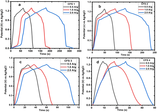
Figure 7. Galvanostatic charge-discharge profile of CFS 1 to CFS 4 at different current densities.
Download figure:
Standard image High-resolution imageFigure 8 show the capacitance retention 8(a), EIS 8(b) and specific capacitance variation 8(c). Our work's better electrochemical performance is ascribed to the electrodes' unique structure and morphology, as well as the electrode material's direct deposition on the substrate without the use of a binder, which greatly reduced electrical resistance and superfluous weight.
In order to check the reaction kinetics and resistances of CuFeS2 electrodes in detail, EIS tests were carried out in the frequency range of 1.0 Hz—100.0 kHz. It is shown in figure 8(b) using the Nyquist plot. Two unique features can be seen on the electrodes. The first is a small, less prominent arc in the high-frequency zone (showing lower charge transfer resistance) with linear vertical spikes in the low-frequency region, peculiar to pseudocapacitors.

Figure 8. (a) capacitance retention plot (inset: stability test) (b) Nyquist plot and (c) specific capacitance versus scan rate of 10–40 cycles deposited CuFeS2.
Download figure:
Standard image High-resolution image
As seen from the bloated area of the Nyquist plot, the CFS 1 electrode exhibits the lowest ESR ∼ 0.44 Ω, and Rct of 1.8 Ω showing good conductivity. Smaller ESR amounts to better electrochemical performance [3, 27]. Smaller resistance maintained by these electrodes could be as a result of the direct deposition done without additional inactive material in the form of binder posing more resistance to the ion intercalation [28–30]. Rct for the films increased as the deposition cycles increased [7, 31]. This is a result of the increase in the electrode thickness [32].
4. Conclusion
CuFeS2 electrodes were synthesized via the SILAR method for 10–40 cycles without the use of a binder for adhesion for supercapacitor application. The electrodes showed excellent structural, morphological, optical and electrochemical features which provided good resistance-free channel for ion intercalation. The CFS electrodes have excellent performance. CFS 1 has the greatest specific capacitance of 537 F g−1 and 93.5% capacitance retention after 400 cycles. CuFeS2 electrodes have been shown to be a potential material for use in energy storage systems.
Acknowledgments
RMO & IA humbly acknowledge NCP for their PhD fellowship (NCP-CAAD/PhD-132/EPD) award and COMSATS for a travel grant for the fellowship.
FIE (90407830) cordially acknowledge UNISA for VRSP Fellowship award and also graciously acknowledge the grant by TETFUND under contract number TETF/DESS/UNN/NSUKKA/STI/VOL.I/B4.33.
We thank Engr. Emeka Okwuosa for the generous sponsorship of April 2014, July 2016, July 2018 and July 2021 conferences/workshops on applications of nanotechnology to energy, health &.Environment and for providing some research facilities.
Data availability statement
The data generated and/or analysed during the current study are not publicly available for legal/ethical reasons but are available from the corresponding author on reasonable request.
Conflict of interest
Authors have no conflict of interest to disclose.