


Abstract
The development of highly conductive and safe electrolytes for sodium-ion batteries is an emerging field beyond lithium battery technologies. In this work we have developed new ionogel electrolytes consisting of a binary mixture of an organic ionic plastic crystal, N-ethyl-N-methylpyrrolidiniumbis(fluorosulfonyl)imide (C2mpyrFSI), mixed with NaFSI supported on a mat of electrospun poly (vinylidene fluoride) nanofibers. The salt mixture near the eutectic composition (35 mol% NaFSI) was selected for further study after a detailed phase diagram analysis and ionogel electrolytes based on this were prepared. The ionic conductivity of the prepared ionogel composite reaches 2.6 × 10⁻³ S cm−1 at ambient temperature. This ionogel membrane possessed a relatively high Na-ion transference number of 0.44 at 50 °C and we demonstrate the performance of a Na metal full cell using a NaFePO4 cathode (1.75–4.0 V). The assembled cells show a good capacity retention with coulombic efficiency close to 100% at various C rates between C/20, C/10 and C/5, achieving 120 mAh g−1 at C/20. The long term charge/discharge performance is also demonstrated. Our study provides a feasible method to prepare highly conductive ionogel electrolytes for future Na-battery applications
Export citation and abstract BibTeX RIS

Original content from this work may be used under the terms of the Creative Commons Attribution 4.0 license. Any further distribution of this work must maintain attribution to the author(s) and the title of the work, journal citation and DOI.
1. Introduction
The ongoing development of high energy density and environmentally friendly energy storage devices is of great importance as the world energy demands increase and we transition to zero carbon emission society. At present, the lithium-ion battery (LIB) is the dominant technology for the majority of applications from personal electronics, electric vehicles, drones and even stationary energy storage [1]. But in recent years, there has been concern raised of relying too heavily on this one technology, due to the extensive use and potential depletion of resources that are required for LIBs, including Li, cobalt (Co) and even high purity graphene [2]. One obvious alternative technology that can replace Li is that based on sodium (Na) which has very similar properties to Li albeit heavier and having a slightly higher electrochemical potential. Na itself is abundant and evenly distributed geographically on earth and thus cost will ultimately be lower. Furthermore, the cathode materials that are paired with Na anodes are typically Co free [3].
The electrolyte is one of the key components in a battery; it provides mass transport of the necessary ions (e.g. Li+ or Na+ ion conductivity) between electrodes, creates the solid electrolyte interphase (SEI) that ultimately suppresses unwanted electrolyte/electrode degradation, and supports long term, efficient cycling. If the electrolyte is in a solid state, it also acts as a separator between the anode and cathode. A good electrolyte candidate for future batteries should be non-flammable, free from leaking and possess high ionic conductivity of the target ion, along with high thermal and electrochemical stability. In order to fulfil all these requirements and enable high energy density, safe devices, the development of next generation electrolytes is crucial.
Gel polymer electrolytes were designed with the attempts to replace the organic liquid electrolytes in the case of LIBs to avoid leakage issues. In traditional cases, lithium or sodium salts are dissolved in organic solvents such as ethylene carbonate, propylene carbonate and later are combined with a polymer matrix to make a gel electrolyte. Many studies have shown superior ion conductivity in these gel polymer electrolytes compared to solid polymer electrolytes, which normally exhibit low conductivity at room temperature [4–7]. The polymer matrix such as poly (vinylidene fluoride) (PVDF), poly (vinyl pyrrolidone) (PVP), poly (methyl methacrylate) (PMMA), poly (vinylidene fluoride co-hexafluoropropylene) (PVDF-HFP) or a polymer blend (e.g. PVDF-PVP, PVDF-PMMA) provides mechanical support in the gel electrolyte system [8–10]. Although there are many studies of gel polymer electrolytes in LIBs, there are still very few reports on their applications in sodium-ion batteries [9, 11]. Furthermore, the incorporation of flammable carbonate rich gel electrolytes in Na batteries still leaves a safety concern, especially when using a highly reactive Na-metal as the anode. In contrast, ionic liquid (IL)-based gel polymer electrolytes, also called ionogels, promises significantly enhanced safety due to non-flammability, high electrochemical stability and high temperature thermal stability of the ILs [12–14].
Ionogels have been widely used in Li batteries. Li et al studied the electrospun based gel polymer electrolyte based on poly(acrylonitrile)/poly(methyl methacrylate) (PAN/PMMA) which was activated with 1 M LiTFSI and room temperature ionic liquid (RTIL) butyl-methylpyrrolidinium bis(trifluoromethanesulfonyl)imide (C4mpyrTFSI). This electrospun polymer matrix exhibits fibrous morphology with high porosity which helps in retaining a high ionic conductivity; reported as 3.6 × 10⁻³ S cm−1 at 25 °C which is promising for practical applications [15]. Similarily, Wang et al reported the composite polymer electrolyte composed of poly(diallyldimethylammonium)bis(trifluoromethanesulfonyl)imide PDADMA TFSI, C3mpyrFSI and a high concentration of LiFSI salt [16]. The addition of electrospun PVDF nanofiber improves the mechanical properties of the electrolyte dramatically, resulting in ultra-flexible composite ionogel electrolytes. The salt concentration was varied till 0.76 molar fraction and an optimized electrolyte membrane with a transference number of 0.53 ± 0.01 was assembled in a full cell with LiNiMnCoO2 (NMC) and LiNi0.8Co0.15Al0.05O2 (NCA) cathodes. These Li-metal solid state batteries showed good performance even at a high voltage of 4.5 V with a cathode areal capacity of 1.1 mAh cm−2. Very recently, Anastro et al reported an ionogel electrolyte for Na-ion battery applications [17].This electrolyte is comprised of poly (ionic liquid) PDADMA TFSI, C3mpyrFSI RTIL, and NaFSI salt. Compared with C3mpyrFSI which has relatively large cations, the use of an IL with smaller cations provides a possibility of enhanced ionic conductivity, likely leading to a lower viscosity and better performance. Thus, we chose the N-ethyl-N-methylpyrrolidiniumbis(fluorosulfonyl)imide C2mpyrFSI system to investigate further in this work. However, instead of being at liquid a room temperature C2mpyrFSI is a high melting (Tm = ∼205 °C) solid which has plastic crystal tendencies, as described below.
Organic ionic plastic crystals (OIPCs), structural analogue of ILs, have drawn intensive attention in applications for solid state batteries [18]. OIPCs are a class of materials which are ordered at low temperatures but at higher temperatures, they undergo one or more solid–solid phase transitions before their final melt. In order to develop an OIPC electrolyte with the secondary component (Li/Na salt), it is most important to study the phase behavior of these binary or ternary mixtures [19, 20]. Recently, C2mpyrFSI was discovered by Masahiro et al to be a room temperature OIPC [21]. This OIPC has been studied extensively for lithium battery applications [22]. Zhou et al studied the phase behavior of a mixture of C2mpyrFSI with LiFSI and formed a free-standing composite electrolyte with PVDF nanofiber, which showed stable cell cycling with Li/NMC at room temperature [23]. For the first Na-battery application of C2mpyrFSI, Hagiwara et al studied the thermal, physical and electrochemical properties of a binary mixture of C2mpyrFSI and NaFSI salt [24]. They investigated the Na-salt concentration effects on the phase behaviour and cell cycling performances at 90 °C using this IL electrolyte. Interestingly, the binary mixture of C2mpyrFSI and NaFSI salt shows an unexpected liquid window, where an outstanding solubility of this salt even at high salt concentration was demonstrated. They also showed the cycling performance of the Na/NVPC (a NASICON-type cathode) at elevated temperature of 90 °C for high salt concentration i.e. 60 mol%.
In this study, extending on Hagiwara et al's work [24], we developed the first ionogel electrolyte system based on a more detailed phase behaviour study by using a combination of DSC, SEM and especially nuclear magnetic resonance (NMR) measurements. We select a 35 mol% NaFSI salt composition to study further in an ionogel where the binary mixture was supported with electrospun PVDF fibers. It was interesting to observe that the fiber swelled readily when combined with the liquid mixture and showed negligible ionic conductivity loss compared to the liquid electrolyte. We also demonstrated the outstanding cell cycling stability and high capacity retention of ionogel electrolytes at 50 °C, suggesting a potential candidate for Na-battery applications.
2. Results and discussion
2.1. Phase behaviour and morphology of binary C2mpyrFSI/NaFSI electrolytes
C2mpyrFSI is a recently discovered OIPC which is a waxy solid at room temperature [21]. The DSC traces of the neat and binary salt mixtures are shown in figure 1. Neat C2mpyrFSI exhibits solid–solid transitions at −72 °C (phase III–II) and at −16 °C (phase II–I), respectively, with a melting point evident at 205 °C. There is a large enthalpy change from phase III–II while a relatively small enthalpy change during transition of phase II–I, which is consistent with previous reports [23, 24]. C2mpyrFSI satisfies Timmermann's criteria with a final entropy of fusion ΔS = 11 J K−1 mol−1 [25], confirming its classification as an OIPC. It exhibits a wide range of plastic phase from −16 to 205 °C. With the addition of up to 4 mol% NaFSI salt, there is no significant change observed for the phase III–II and phase II–I but there is a decrease in the melting point from 205 to 185 °C. At 5 mol % NaFSI, a small shoulder is observed in the phase III–II transition at −69 °C above 5 mol% mixtures, figure 1(b), with a further decrease in the melting point to 154 °C. The second solid–solid phase transition (II–I) remains the same with a consistent decrease in enthalpy as shown in figure S1 and table S1 (available online at stacks.iop.org/JPMATER/4/044005/mmedia). The phase III–II does not appear for the sodium-rich phase mixtures (from 30 to 80 mol%), and there is no prominent melting peak observed. Interestingly, an exothermic peak appeared for 30 mol% at 150 °C and again appears for the 80 mol% mixture at high temperature. The 35–70 mol% mixtures exhibit a predominantly liquid phase with a prominent Tg at very low temperatures. Neat NaFSI salt possesses a solid–solid transition at 98 °C before melting at 104 °C, hence the peak observed for 80 mol% (82 °C) and 90 mol% (94 °C) are likely related to the NaFSI salt. At 30 mol%, a new Tg is observed at −88 °C (figure 1(b)) [24]. This mixture appears to have both solid and liquid phases at very low temperatures. At 35 mol% the material shows complete IL behavior with no solid–solid transitions. To determine precisely the eutectic composition, likely between 30 and 35 mol% NaFSI, a 32 mol% mixture was analysed but no changes were observed compared with the 30 mol% sample (figure S2), except for a decrease in enthalpy of the phase transitions (III–II and II–I), thus we can infer that the eutectic phase is observed between 32 to 35 mol%. The 35 mol% mixture appears to be a transparent liquid and, with increasing salt concentration, a viscous liquid is formed up to 70 mol%. The Tg of samples with salt concentration from 30 to 90 mol% NaFSI salt, increases from −92 to −57 °C, respectively. The Tg data for 35 and 40 mol% mixtures is shown in figure 1(c). The phase diagram is shown in the supporting information figure S3.

Figure 1. (a) DSC traces of neat C2mpyrFSI, neat NaFSI and their mixture at 5 °C min−1. (b) DSC traces of neat C2mpyrFSI and for the 5, 10, 20 and 30 mol% binary salt mixtures at 2 °C min−1, (c) glass transition temperature (Tg) of 35 and 40 mol% mixtures. All the samples were measured at 2 °C min−1.
Download figure:
Standard image High-resolution imageIn order to gain further insight into the influence of the NaFSI salt on phase behaviour and morphology, SEM images were obtained for the neat C2mpyrFSI (figure 2(a)) and the binary mixtures with 5, 10 and 20 mol% salt concentrations (figures 2(b)–(d) respectively). The image of the neat C2mpyrFSI shows slip planes with no significant aggregates, but with the addition of NaFSI salt, the formation of contrasting phases is observed. For the 5 mol% mixture (figure 2(b)), there is a clear phase separation, and we can further conclude that the solid-phase is related to the OIPC rich region considering the characteristic solid–solid transition peaks of C2mpyrFSI (5 mol% in figure 1(a)). In addition, given the emergence of exothermic peaks in high NaFSI concentration samples (figure 1), we believe that these exothermic peaks are related to the Na-rich phase (highlighted by an arrow in the SEM images, figures 2(c) and (d)). For the 10 mol% mixture, the images show a more liquid-like nature with less solid phases in figure 2(c). Furthermore, the SEM for the 20 mol% mixture, figure 2(d), appears to be domitated by a liquid phase which also agrees with DSC traces that shows a decreased enthalpy (table S1)
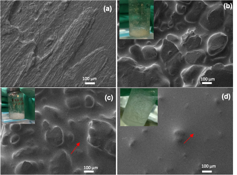
Figure 2. SEM images showing the morphology of binary systems of (a) neat C2mpyrFSI, (b) mixed with 5 mol% NaFSI, (c) 10 mol% NaFSI, (d) 20 mol% NaFSI at an acceleration voltage of 2 kV. Inserted figures are the photos of binary mixtures of relevant composition.
Download figure:
Standard image High-resolution imageTo further understand the phase composition and the distribution of sodium in the binary salt mixtures, sodium mapping was performed for the 5 and 20 mol% salt mixtures, using SEM- energy dispersive x-ray analyzer (EDX). Figures 3(a) and (c) show the surface morphology images for 5 and 20 mol% mixtures recorded at 5 kV for increased sensitivity of the Na-mapping. Interestingly for the 5 mol% salt mixture, sodium is accumulated around the grain boundaries as highlighted in figure 3(b). This is beneficial for electrolyte design since previous studies show that grain boundaries play an important role in the ion conduction process [26, 27]. This is evident in these binary mixtures because, in addition to the presence of the sodium surrounding the grain boundaries, the mixtures also show an increase in ion conductivity, compared to the neat C2mpyrFSI. To compare the amount of sodium at the grain boundary to that within the grain, a spot analysis from the sodium map was performed on the 5 mol% mixture, which shows the percentage of sodium to be higher at the grain boundary at 2.1% Na, compared to 1.5% and 1.2% Na within the grain (highlighted by arrows in figures 3(a) and (b)). For the 20 mol% mixture, an even distribution of sodium is evident from (figures 3(c) and (d)), as this system has a higher sodium salt concentration within the liquid dominant phase.

Figure 3. SEM image and EDX mapping of sodium for (a) and (b) the 5 mol% and (c) and (d) 20 mol% binary mixtures. Red dotted lines refers to the grain boundaries.
Download figure:
Standard image High-resolution image2.2. Ionic conductivity and ion dynamics of binary C2mpyrFSI/NaFSI
The ionic conductivities for the neat C2mpyrFSI and the binary mixtures of C2mpyrFSI-NaFSI were measured in the temperature range −20–80 °C. The conductivity of the neat C2mpyrFSI and the binary mixtures that exist in a liquid state are shown in figure 4(a), while the ionic conductivities of all samples at 30 and 50 °C are shown in figure 4(b). Neat C2mpyrFSI exhibits an ionic conductivity of 1.4 × 10⁻⁶ S cm−1 at −20 °C and the conductivity increases with increasing temperatureat room temperature, the conductivity is increased by one order of magnitude and further increases at 50 °C. For 30 mol% till 50 mol%mixtures, upon addition of NaFSI salt, the ionic conductivity increases within the entire temperature range compared with neat OIPC. From the DSC traces (figure 1(a)), we found that upon addition of NaFSI salt there is greater disorder (as observed by a decreased enthalpy) even at lower temperature, around −70 °C. Such disorder influences the ion conduction process [24], which is evident in these systems. A very small addition of NaFSI salt (1 mol%) leads to an increase in conductivity by one order of magnitude, over the entire temperature range and as the system becomes less ordered, there is a further sharp increase in conductivity figure 4(b) We note, however, that we cannot distinguish between a eutectic liquid in the grain boundary contributing to the high conductivity as suggested in many OIPCs doped with Li salts, as opposed to intrinsic changes within the OIPC [28]. The 35 mol% NaFSI mixture shows a tremendous increase in conductivity by almost three orders of magnitude (2.6 × 10⁻³ S cm−1) at room temperature, compared to neat C2mpyrFSI. Surprisingly these systems display high conductivity with liquid behaviours even with high salt concentrations. For example, although the 70 mol% NaFSI mixture is viscous, it still shows conductivity of approximately 1.3 × 10⁻⁴ S cm−1 at room temperature and 1 × 10⁻³ S cm−1 at 50 °C, respectively. All these binary salt mixtures show high conductivities compared with most of sodium-based OIPC electrolytes studied so far, even at high salt concentration [29–31]. It is worth noting that the compositions with a sodium-rich phase, even at high salt concentrations, i.e. between 50 and 70 mol % NaFSI, an ionic conductivity similar to that of the IL C3mpyrFSI with 50 mol% NaFSI is observed [32]. Figure 4(b) shows the conductivity dependence on salt concentrations at 30 and 50 °C. When the binary mixture is in its solid phase it shows an increase in ionic conductivity by two orders of magnitude compared with neat OIPC.

Figure 4. (a) Ionic conductivities of C2mpyrFSI and liquid binary mixtures containing NaFSI, from −20 to 80 °C. (b) A comparison of ion conductivity for all samples at both 30 and 50 °C.
Download figure:
Standard image High-resolution imageNMR measurements provide an insight into the rotational and translation motions of the specific nuclei in a given electrolyte system, by analysis of the peak width and shape. The spectral pattern and full width at half maximum (FWHM) values at variable temperatures are shown in figures 5(a) and (b), respectively. The narrow peaks are usually associated with a mobility of the ions. NMR allows us to study individual ions by using different nuclei; 1H NMR is used to study C2mpyr+ cation, 19F for the FSI- anion and 23Na for mixtures containing Na ions. In general, we observe that all the ions have less mobility at ambient temperature relative to higher temperatures. The 1H and 19F spectra confirm that the salt-containing binary mixtures show a higher mobility than the neat C2mpyrFSI even at room temperature, as evident by the narrower peak widths shown in figure 5(b). Figure 5(a) shows, via 1H signals, that the cation is less mobile in neat C2mpyrFSI at room temperature, compared to 60 °C . The 19F spectra indicate that the mobility of FSI anions also increases at 60 °C in the neat OIPC where the linewidth is almost equal to that of the 5 and 30 mol% mixtures at 60 °C. For 23Na NMR, surprisingly the 5 mol% NaFSI mixture shows a narrower line reflecting a higher mobility compared to the 30 mol% mixture (figure 5(a)). Given that the 5 mol% mixture is below the eutectic composition while the 30 mol% mixture is almost at the eutectic composition, this may suggest different coordination environments as observed in IL-based electrolyte reported previously [33–35].

Figure 5. (a) NMR spectra of 1H, 19F, 23Na NMR for neat OIPC, 5 mol% and 30 mol% mixtures and (b) FWHM values of 1H, 19F, 23Na NMR with respect to temperature.
Download figure:
Standard image High-resolution image2.3. Highly conductive ionogel electrolytes
The critical parameters for an electrolyte in a battery are their high ionic conductivity, high transference number of the target ion (e.g. Na+ in the current case), a wide electrochemical window and safety. As shown in figure 4(a), the addition of Na-salt to the OIPC increased the base conductivity by several orders of magnitude. Usually, an ionogel is prepared from an IL electrolyte and a polymer support, in this case electrospun PVDF fibers and ionogel preparation is shown in figure 6(a), the conductivity can be significantly impacted [17, 36]. Surprisingly, as evidenced from the figure 6(b), there is no significant change in the conductivity in the PVDF nanofiber-C2mpyrsFSI-NaFSI ionogel relative to the liquid C2mpyrFSI-NaFSI electrolyte at temperatures below 25 °C, whereas with increasing temperature, the ionogel conductivity actually increases slightly. Such an unexpected result of enhanced conductivity in a gel relative to the liquid, suggests specific interactions with PVDF. Further SEM images (figure S4) confirm that the average diameter of original fibers and fibers in ionogels are 622 and 735 nm, respectively, suggesting PVDF swelling in ionogels. The PVDF swelling by IL mixture is probably due to the good compatibility and potential interactions between FSI anions and PVDF as proposed in our previous studies [37]. Following the outstanding conductivity observed in this ionogel, further electrochemical characterisation was undertaken as discussed below.

Figure 6. (a) Procedure for composite ion gel electrolyte membrane consisting of 35 mol% NaFSI salt and 65 mol% C2mpyrFSI. (b) Ionic conductivity of 35 mol% binary electrolyte mixture and composite electrolyte.
Download figure:
Standard image High-resolution imageThe transference number is measured and calculated according to Bruce–Vincent method as reported previously [38]. Figure 7(a) shows the current profile as function of time and figure 7(b) shows the impedance of Na/PVDF-35 mol% gel electrolyte/Na cell before and after polarization under 10 mV applied voltage. The transference number of PVDF-35 mol% gel electrolyte obtained is 0.44 at 50 °C. This value is significantly higher than those of concentrated 50 mol% C3mpyrFSI + NaFSI electrolyte (0.30) as well as the equivalent lithium based electrolyte (50 mol% Li-C2mpyrFSI-PVDF nanofiber) (0.37) [23, 39] even though the salt concentration is lower (usually transference number increases with increasing alkali metal salt [40]). This high transference number of Na+ may give us a possible explanation for the high ionic conductivity. Usually the pyrrolidinium cation has a higher diffusion coefficient in these systems compared with the FSI or the alkali metal cation, leading to an overall lower Li+/Na+ transference number observed in the previous studied systems [41]. But here a TNa+ of 0.44 suggests that the sodium is not being impacted by the presence of the PVDF, and if anything, possibly the FSI anion may be hindered by interacting with the fluorophilic PVDF fiber interface [37, 42]. The high ionic conductivity coupled with a high TNa+ makes this system desirable for Na+ battery applications as presented below.

Figure 7. (a) Current vs time profile at 50 °C. (b) Electrochemical impedance spectra of the Na/PVDF-35 mol% gel electrolyte/Na cell before and after polarisation.
Download figure:
Standard image High-resolution image2.4. Long-term cycling stability against Na-metal
To test the cycling stability performance of the ionogel electrolyte, Na symmetric cells were constructed. Cycling was undertaken at 50 °C and the results are shown in figure 8. We can observe that this ionogel electrolyte is stable up to a current density 0.4 mA cm−2 with an overpotential of only 50 mV. This is at least as good performance as the C3mpyrFSI IL with 50 mol% NaFSI [32] but in a solid state gel electrolyte. This performance was reproducible across multiple cells.

Figure 8. Symmetric Na/35 mol%-PVDF/Na cell cycling performance. (a) Performance of Na/Na symmetric cell cycled at different current density at 50 °C. (b) Long term galvanostatic cycling stability under a current density of 0.1 mA cm−2 (plating/stripping capacity: 0.1 mAh cm−2). (c) The zoomed in view of last ten cycles as highlighted in (b). (d) The Nyquist plots of Na/35 mol%-PVDF/Na cell collected before cycling and during cycling for every 100 cycles. All of the tests were done at 50 °C.
Download figure:
Standard image High-resolution imageThe long-term stability is also a very important parameter to consider for high performance devices. As shown in figure 8(b), the 35 mol%-PVDF ionogel electrolyte shows outstanding stability during long term of 500 plating/stripping cycles (1000 h), with absence of significant voltage fluctuation or short circuit whilst still maintaining a low overpotential (<20 mV) throughout the cycling duration, indicating efficient and stable Na+ transport in the electrolyte and SEI. The evolution of the EIS impedance is shown in figure 8(d) and suggests the interfacial resistance does increase incrementally from 200 Ohm after 100 cycles to 300 Ohm after 500 cycles. This also confirms good stability even with long-term cycling at 50 °C, although the increase of interfacial resistance could be attributed to the modification of the SEI, becoming less conductive during long-term cycling. Further cycle efficiency test confirms that the 35 mol%-PVDF ionogel electrolyte shows a relatively high efficiency of 84.2% at 50 °C (figure S5). The cycling plating/stripping stability at room temperature was also tested figure S6, however only a short cycling life is achived, probably due to the relatively low cycling efficiency related to SEI formation at low temperature. It should be noted that, compared with some literature [43], the current density is still relatively low, therefore how to improve cycling stability at high current densities and to understand the mechanism of formation and evolution of the SEI requires future work.
2.5. Na/NaFePO4 cell cycling performance
The electrolyte compatibility was tested against an intercalation cathode NaFePO4 at different C-rates (C/20, C/10, C/5) at 50 °C as shown in figure 9(a), unlike the recent report published by Hagiwara et al for C2mpyrFSI + NaFSI /NVPC at 90 °C which is near to the melting point of sodium metal (98 °C) . The highest cut-off voltage before instability was observed was 4.0 V, beyond which the cell was unstable figure 9(b). The specific capacity of the cell at C/20 was above 120 mAh g−1, which slightly reduced for C/10 and C/5 current rates. The average columbic efficiency achieved was close to 100% (>99%) for all the different current rates. The C-rate capability (up to C/2) of ionogel is also confirmed with another duplicate cell and the performance is shown in figure S7. In comparison, the binary salt mixture of C2mpyrFSI/ NaFSI against an NVP cathode demonstrated by Hagiwara etal had a capacity less than 100 mAh g−1 [24].

Figure 9. Na/NaFePO4 cell cycling. (a) Charge–discharge capacity and efficiency vs cycle number at different C-rates, C/20, C/10 and C/5 at 50 °C. (b) Charge–discharge profile curves for C/5 and C/10 current rates. The NaFePO4 active material loading is 1.7 mg cm−2.
Download figure:
Standard image High-resolution image3. Conclusions
In this work, an ionogel electrolyte is developed based on investigations of phase behaviour, morphology and ion dynamics of a binary salt mixture of C2mpyrFSI + NaFSI. It is found that there is no significant change of the conductivity in a composite electrolyte with PVDF-base composite ion gel electrolyte compared to the C2mpyrFSI-NaFSI mixture at lower temperatures, in contrast to previous ionogel reports for related systems. The conductivity for both liquid and ionogel electrolyte at 35 mol% IL, was 3 × 10⁻³ S cm−1 at room temperature with a transference number of 0.44 at 50 °C in case of the ionogel. Na symmetric cells as well as Na/NFP full cell were demonstrated to cycle with high stability. In particular, a low polarization potential of less than 20 mV is demonstrated after plating/stripping 500 cycles (1000 h) at 0.1 mA cm−2, 50 °C, indicative of a stable solid-electrolyte-interface (SEI) layer formed on the Na-metal. The Na/ionogel/NFP cells show good C-rate capability and long-term stability with a coulombic efficiency of around 99.9% and discharge capacity of 117 mAh g−1 at 50 °C.
4. Experimental section
4.1. Materials and sample preparation
Sodium bis(fluorosulfonyl)imide (NaFSI, 99.99%) was purchased from Solvionic, and dried in Schlenk line at 50 °C overnight before use. N, N-Dimethylformamide (DMF, HLPC grade), Acetone (HPLC grade) and Na foil (99.99%) were purchased from Sigma-Aldrich. Polyvinylidene fluoride (powder) was purchased from Kureha Chemicals, Japan and used as received.
C2mpyrFSI was synthesized according to a previously reported procedure [24]. In particular, C2mpyrBr (16.565 g, 85 mmol) and potassium bis(fluoromethanesulfonyl)amide (19.268 g, 88 mmol) were dissolved separately in 100 ml of distilled water. Upon mixing the solutions, a white precipitate formed. The solution was stirred at room temperature overnight. The product was dissolved in 200 ml of ethyl acetate, followed by washing with distilled water several times (7 × 100 ml). The organic solvent was removed in vacuo, to obtain the white sticky solid of 1-methyl-1-ethylpyrrolidinum bis(fluoromethanesulfonyl)imide (C2mpyrFSI). The product was dried at 60 °C for 72 h, resulting in a total yield of 50% (12.455 g). The purity of the product was confirmed by analysis of the chemical and physical properties, using characterization techniques, including NMR, mass spectroscopy, microanalysis. The potassium content is 500 ppm and bromide content is 200 ppm.
The synthesis of triphylite-NaFePO4 (analogous to triphylite -LiFePO4, cathode material used in commercial Li-ion batteries) was carried out by using abundant and low-cost reagents, which consists of a two-step reaction: (a) chemical oxidation of LFP using Na2S2O8 (aq.) as the oxidizing agent and (b) chemical sodiation of the obtained FP by Na2S2O3(aq.) [44].
The PVDF nanofibers were synthesized by electrospinning. First, PVDF was dissolved in DMF/acetone mixture (1:1 volume ratio) and sonicated for 2 h. The the solution was left stirring at 60 °C overnight to achieve a homogeneous solution. Then the solution was loaded in a 10 ml syringe connected with Terumo, 20 G × 1.5 needle. The rotating drum (earthed) was covered with aluminium foil and positioned 20 cm away from the needle tip. The voltage applied was 17.5 kV and the solution flow rate was 4 ml h−1. The obtained fibrous mat was around 160 μm thick for electrospinning time of 2 h. The PVDF nanofiber mat was then punched into membranes with a diameter of 14.5 mm and finally dried in Schlenk line at 50 °C for 24 h.
The binary salt mixture was prepared by mixing 35 mol% of NaFSI salt in 65 mol% C2mpyrFSI inside an Ar-filled glove box. After forming homogenous solution, the binary electrolyte mixture was further dried under Schlenk line and carefully transferred into glovebox for future use.
The ionogel composite electrolyte membrane is composed 10 wt% of PVDF fiber and 90 wt% of the binary salt mixture. The binary electrolyte was impregnated on the PVDF nanofiber and allowed to swell overnight inside the Ar-filled glove box, then the obtained flexible membranes are obtained.
Cathode films were prepared by using a slurry composed of 80 wt% of NaFePO4 active material, 10 wt% of PVDF binder and 10 wt% of conductive carbon (C65, Timcal). First, a pre-weighted amount of NaFePO4 and carbon C65 were ground in an agate mortar. Then a binder solution was prepared by dissolving PVDF powder in NMP (N-2-methyl-pyrrolidinone) in a small beaker followed by mild stirring for 30 min. Afterwards, the ground NaFePO4 and carbon solid mixture was added to the beaker with stirring mild overnight. The slurry was then cast onto aluminum foil using a doctor blade to obtain cathode film. To remove the solvent, the film was firstly dried at 80 °C for 24 h, then 100 °C under vacuum overnight. Finally the film was punched into disks to obtain the electrodes. The diameter of each cathode is 8 mm (0.5 cm2).
4.2. Differential scanning calorimetry (DSC)
DSC is a technique commonly used in materials research to obtain information on the thermal properties of a material. The instrument used in this research was a Mettler Toledo DSC822e with an operational temperature ranging from −150 to 700 °C. The sample (5–10 mg of vacuum-dried material) was placed in a crucible and sealed in the glove box, under argon. All the measurements were controlled by heating and cooling units controlled by STARe V6.10 software. All data were processed and analyzed using this software. All samples, including the neat OIPC and the binary mixtures of OIPC and NaFSI, were analyzed over the temperature range of −110–230 °C, with a heating rate of 5 °C min−1. The DSC instrument was calibrated with cyclohexane. Three thermal cycles were performed for all the samples; the first cycle was heated to 50 °C, the second cycle to 150 °C and the third cycle to 230 °C. Each cycle was returned to −110 °C and held there for 30 mins in the isothermal state. The enthalpy changes reported are normalized to the weight of plastic crystal.
4.3. Scanning electron microscopy (SEM)
SEM was performed to observe the morphology of the binary mixtures at varying concentrations, to understand the formation of phases. Sodium mapping was also performed to observe the distribution of sodium in the binary salt mixtures. SEM was conducted on a JEOLJSM-IT300 SEM. SEM images were acquired at an accelerating voltage of 2 kV, while the sodium mapping were acquired using 5 kV through an EDX. The SEM samples were prepared inside a dry, Ar-filled glove box.
4.4. Electrochemical impedance spectroscopy (EIS)
EIS experiments were performed to understand the ion dynamics of the neat OIPC and OIPC-salt mixtures. Measurements were performed by AC impedance spectroscopy using Biologic MTZ-35 in the frequency range from 1 Hz to 10 MHz and with a voltage amplitude of 0.01 V, over a temperature range from −20 to 80 °C. An equilibrium time of 20 mins was used.
The ionogels were sealed in a coin cell, due to the hygroscopic nature of the sample. The coin cells were then placed inside a custom-built barrel cell for measurement.
For the liquid samples, a dip cell which consisted of two platinum wires, separated in a glass rod and vacuum sealed with an O-ring, was used. A 0.01 M KCl solution was used to determine the cell constant. The dried sample was placed in a glass vial and the two platinum wire electrodes were dipped into the sample and sealed. In both cases, the cells were placed inside a brass block which was connected to the thermocouple for temperature control. The conductivity was calculated from the X-axis intercept of the Nyquist plot.
4.5. Solid state nuclear magnetic resonance spectroscopy (solid-state NMR)
Solid-state NMR was performed to understand the local dynamics and atom mobility in the binary system compared to the neat C2mpyrFSI. In this work, all experiments were performed using Bruker Avance III 500 MHz Ultrashield wide-bore spectrometer equipped with a 5 mm pulse-field gradient probe. All the results were analyzed using Topspin 3.5 software.
All samples were prepared inside a dry glove box under an argon atmosphere. Samples were loaded in a glass tube and placed inside a custom-designed vacuum-sealed chamber to avoid moisture uptake during transportation and later this chamber was stored in an Ar-filled glove box at the NMR facility center. Samples were loaded in a 4 mm rotator for measurements and placed in the strong magnetic field in order to obtain the spectra with response to the radiofrequency radiation. The measurements for various nuclei (19F, 1H and 23Na) were performed for the neat C2mpyrFSI and the 5, 30 and 70 mol% salt mixtures, over a temperature range from −20 to 80 °C. FWHM of specific nucleus signals were obtained by fitting the peaks with Gaussian/Lorentzian function.
4.6. Electrochemical characterisation
Na/Na symmetric coin cells, which consist of two sodium metal electrodes separated by a with ionogel electrolyte of 200 ± 10 μm thickness were assembled inside an Ar-filled glove box. Sodium metal plating and stripping was studied at different current rates for the 35 mol% mixture ionogel at 50 °C. A Neware BTS 4000 with Neware BTS software was used.
Na/NaFePO4 (NFP) cell preparation followed the symmetrical cell procedure, except the cathode NFP (8 mm diameter) foil replaced one Na electrode. The NaFePO4 active material loading is 1.7 mg cm−2.
4.6.1. Na+ transference number measurement
The Na+ transference number (TNa+) of the composite electrolyte was measured by using Bruce–Vincent method [45]. This method is based on CV polarisation and EIS measurements

where Ri0 and RiS are initial and steady state interfacial resistance, respectively. ΔV is applied constant potential, and I0 and Is are the initial and steady-state currents.
The following equivalent circuit (see figure 10 above) was used to obtain the interfacial resistance.

Figure 10. Equivalent circuit diagram for calculating interfacial resistance.
Download figure:
Standard image High-resolution image
Where R1 is the bulk resistance of electrolyte. R2 and R3 represent the resistance related with two electrode surfaces. The software is EC-Lab V11.27 and the fitting method is Randomize + Simplex. We used Ri = R2 + R3 to calculate the interfacial resistance before and after polarization.
Acknowledgments
Authors would like to acknowledge for The Australian Research Council (ARC) is acknowledged for support through DP160101178 and Deakin University postgraduate research scholarships. Authors also acknowledge Dr Ruhamah Yunis for her help with OIPC synthesis and Battery Technology Research Innovation Hub (BatTRI-Hub) at Deakin University for cathode preparations. MG acknowledges the Basque Government and the Ministerio de Ciencia, Innovacioén y Universidades of Spain through the Elkartek program CICe2020 and PID2019-107468RB-C22 for the finantial support, respectively.
Data availability statement
The data that support the findings of this study are available upon reasonable request from the authors.