

Abstract
Efficient storage of hydrogen is one of the biggest challenges towards a potential hydrogen economy. Hydrogen storage in liquid carriers is an attractive alternative to compression or liquefaction at low temperatures. Liquid carriers can be stored cost-effectively and transportation and distribution can be integrated into existing infrastructures. The development of efficient liquid carriers is part of the work of the International Energy Agency Task 40: Hydrogen-Based Energy Storage. Here, we report the state-of-the-art for ammonia and closed CO2-cycle methanol-based storage options as well for liquid organic hydrogen carriers.
Export citation and abstract BibTeX RIS
1. Introduction
The transition from a carbon-based to a carbon-emission-free energy system demands the development of new key technologies that can store and utilize renewable energy. Hydrogen is one of the most promising candidates to replace fossil fuel sources for mobile and stationary applications. However, hydrogen generated by renewable electricity needs to be stored efficiently. The requirements for suitable hydrogen storage systems depend on their applications. For mobile applications based on solid-state storage systems, many factors such as reversibility, kinetics, thermodynamics, safety, volumetric and gravimetric energy density, weight and size of the storage system, as well as costs and efficiency are essential criteria for successful implementation [1].
So far, different storage technologies that have been considered show specific limitations. Physical storage methods such as high-pressure or low-temperature storage require relatively harsh conditions. Compression of pure hydrogen at 70 MPa is nowadays used for fuel cell driven vehicles [2]. The high pressures require robust tanks made of high-strength materials. Liquid hydrogen storage needs cryogenic temperatures; therefore, the tanks must be well insulated [2]. Since insulation is never perfect, boil-off losses of hydrogen cannot be avoided [3]. Liquid hydrogen is therefore not attractive for mobile applications. The volume of the stored hydrogen can be reduced compared to hydrogen gas under standard conditions. However, the low operating temperature consumes about 30% of the energy content of the stored hydrogen [4].
For hydrogen storage in solids, hydrogen adsorption on the surface of high surface area materials such as metal-organic frameworks (MOFs) or carbon materials has been considered [5–9]. However, physisorption works well at low temperatures of 77 K, while adsorption at room temperature is insufficiently low [10–12].
Because gas adsorption is an exothermic process, large amounts of heat are released during the charging process. For MOF-5 as a hydrogen absorber, the storage of 5.6 kg of H2 would result in 10 MJ of heat which must be dissipated [13]. This would require effective heat management [14, 15]. Intensive studies have been dedicated to interstitial hydrides, complex metal hydrides such as metal borohydrides or metal aluminum hydrides, imides and amides as solid-state hydrogen storage materials [16–20]. For most of these compounds, the limiting factors for successful reversible hydrogen storage under acceptable operating conditions are kinetic issues and the irreversibility of dehydrogenation.
Liquid-state hydrogen carriers comprise liquid organic hydrides, ammonia, formic acid (FA), or methanol (MeOH). While liquid organic hydrides and ammonia do not release any CO2, MeOH possesses a high potential but only in the recycling of carbon via hydrogenation of CO2 [4].
The use of ammonia as an energy carrier is strongly supported by the high volumetric (108 kgH2 m−3 NH3 at 20 °C and 8.6 bar) and gravimetric (17.8 wt%) energy densities [21]. Ammonia can be further used either by the catalytic cracking into COx -free hydrogen [22, 23] or in power generation devices such as fuel cells, combustion engines, and gas turbines (GTs) with zero carbon footprint. The usage of ammonia as an intermediate hydrogen carrier will be only an acceptable alternative to fossil hydrogen carriers such as natural gas (NG) if the synthesis is achieved via 'green' sustainable synthesis routes. Conventional synthesis via thermal catalysis is constrained by a large carbon footprint; therefore, alternative processes for the generation of green but also economically affordable ammonia are required. On the other hand, ammonia cracking for hydrogen recovery requires the development of efficient, environmentally sustainable catalysts. Therefore, both synthesis and cracking technologies can be improved and require further developments before commercial implementation.
Two other candidate liquid hydrogen carriers are MeOH and dimethyl ether (DME), with volumetric and gravimetric densities of 99.7 kgH2 m−3 and 12.6 wt% for MeOH under ambient conditions versus 88.9 kgH2 m−3 and 13.1 wt% for liquified DME at 20 °C and 5.0 bar [24]. Hydrogen is stored via catalytic conversion with a carbon source (ideally direct-air captured CO2 for a carbon neutral product) followed by distillation-based purification. Steam reforming of both compounds via traditional catalytic reactors regenerates the H2/CO2 (and trace CO), after which selective removal of the H2 is required via pressure swing adsorption (PSA), membrane, or solvent-based carbon capture [25, 26]. If the use case for H2 storage is power generation, both carriers can be introduced into fuel cell technologies, with CO2 and water vapor as products [27]. Both carriers represent promising pathways for a global reduction in CO2 emissions from hard-to-abate sectors, such as steelmaking, and a reduction in net fossil fuel consumption.
The third group of liquid hydrogen carriers comprises a group of hydrocarbon molecules that bind hydrogen reversibly. In these round trip carriers, the hydrogen is introduced using catalysts to hydrogenate unsaturated organic molecules [28]. These compounds are called liquid organic hydrogen carriers (LOHCs). One of the challenges with conventional LOHCs, e.g. methylcyclohexane (MCH), perhydro-dibenzyl toluene (H18-DBT), and N-ethylcarbazole, is the large enthalpy for release of hydrogen requiring high temperatures, lowering the overall round trip efficiency.
This review will summarize the state-of-the-art on the synthesis of green ammonia, ammonia cracking and MeOH with a specific focus on heavy-duty transportation systems and LOHCs for stationary energy storage.
2. Ammonia
2.1. Synthesis
2.1.1. Traditional synthesis
Nowadays, the industrial production of ammonia is carried out via the Haber–Bosch process (equation (1)) using NG or other fossil fuels for the generation of hydrogen.

The amount of ammonia produced in 2020 was around 183 million metric tons [29–31], with an energy consumption of approximately 2% of the global energy consumption and primary CO2 emissions of about 450 Mt [32]. The synthesis of NH3 from hydrogen and nitrogen via iron-based catalysts requires temperatures up to 500 °C and a pressure of 20 MPa [33]. Actually, about 96% of the hydrogen used for the ammonia synthesis via the Haber–Bosch process is obtained from fossil fuels. Only about 4% is generated by water electrolysis. For energy generation mainly fossil fuels are used and only about 0.7% come from renewables or carbon capture, use and storage [34–37]. Due to high CO2 emissions caused by the generation of hydrogen from fossil fuels, there is great demand for alternative and sustainable synthesis processes. To make ammonia an energy vector for an emission-free energy cycle, the generation of hydrogen for the synthesis process must be based on renewable energy sources. There are several options such as the photo-, electro-, photoelectrochemical splitting of water or biochemical hydrogen generation such as dark fermentation. However, this research field is far beyond the scope of this article. At this point, we refer to excellent review papers, which focus exclusively on the generation of hydrogen [34, 38, 39]. In the following chapter, we will focus on several novel strategies for the synthesis of ammonia as potential future alternatives to the conventional Haber–Bosch process.
2.1.2. Chemical looping process
The chemical looping process decomposes a reaction into multiple subreactions that take place in different spaces or times. Through the chemical looping process, the overall reaction can be optimized by adjusting each step's thermodynamics and kinetic properties [40–42]. Moreover, the chemical looping ammonia synthesis (CLAS) can be operated under low-pressure conditions [43]. To improve the CLAS process, it requires to design and optimize N carrier materials and develop efficient catalysts for each subreaction.
The most common used N carriers are metal nitrides (MNs). According to the hydrogen source of reactants, the reported CLAS processes can be divided into two categories: the H2O + N2 chemical looping (denoted as H2O–CL, figure 1(a)) and the H2 + N2 chemical looping (denoted as H2–CL, figure 1(b)) [44]. In the H2O–CL, ammonia is produced by hydrolyzing MNs, and N2 is fixed by reacting with metals or metal oxides. For this loop, the reactions for regeneration of MNs or metals are usually strongly endothermic, which can be only proceeded under extremely high temperatures (⩾1000 °C). AlN–Al2O3 [45], Cr–Cr2N–Cr2O3 [46], etc are representative of H2O–CL. In the H2–CL process, generating ammonia is via hydrogenation of the N-rich MNs, and N2 is fixed by reacting with N-poor nitrides. Typical systems include Mn4N–Mn6N2.65 [47] or Co6Mo6N–Co3Mo3N [48], in which the hydrogenation of N-rich MNs reactions usually encounter kinetic obstacles at low temperatures and are thermodynamic non-spontaneous at high temperatures. For example, hydrogenation of Mn6N2.58, Ca3N2, or Sr2N to produce ammonia at a low rate of ca. 55.3, 98, or 81 μmolNH3 g−1 h−1 at 550 °C, and the full cycle of H2-CLAS based on MNs have yet to be demonstrated experimentally (figure 2(b)) [47].

Figure 1. Three types of chemical looping ammonia synthesis processes. H2O–CL (a) H2–CL (b) and AH–CL (c). (a)–(c) Reproduced from [44], with permission from Springer Nature.
Download figure:
Standard image High-resolution image
Figure 2. (a) Thermodynamic analyses of AH–CL. Reproduced from [44], with permission from Springer Nature. (b) Comparison of NH3 production rates of AH–CL, H2–CL, and conventional thermo-catalytic process. The data of Mn6N2.65, Ca3N2, and Sr2N were taken from [47]. The activities of Co3Mo3N and Fe–K2O–Al2O3 were taken from [53]. The others data were taken from [44].
Download figure:
Standard image High-resolution imageGao et al recently discovered a new class of N carriers, metal imides (ANH), for CLAS [44]. This finding comes from the accumulation of knowledge about the basic properties of alkali and alkaline earth metal amide, imide, nitride, hydride and the reactions between them, as well as their applications in hydrogen storage, catalytic ammonia synthesis and decomposition [49–51]. It was found that N2 can be reduced and fixed by some alkali or alkaline earth metal hydrides (AH) to generate imides accompanied by hydrogen releasing (equation (2)), simultaneously the imides react with H2 to produce NH3 and regenerate AH (equation (3)). A new chemical looping process (denoted as AH–CL, figure 1(c)) was proposed in light of this. The features of this CLAS are the reduction of dinitrogen taking place by hydridic H in AH, and NH3 production by hydrogenation of ANH through the disproportionation of dihydrogen. Thermodynamic analysis shows that various AH–ANH pairs can mediate CLAS, in which LiH–Li2NH and BaH2–BaNH pairs possess suitable thermodynamic properties for both steps I and II (figure 2(a)). Thermodynamically, low temperature is favorable to the AH–CL. However, a low ammonia production rate (198 μmolNH3 g−1 h−1, figure 2(b)) is achieved over the BaH2–BaNH system until 300 °C, mainly due to a severe kinetic resistance on the nitrogen fixation step,


Another critical challenge of CLAS research is slow kinetics, calling for more efficient catalysts to improve nitrogen fixation rates and ammonia production over various nitrogen carriers. Gao et al found that 3d transition metals (TMs) (Ni, Fe, and Co) or their nitrides (Mn4N) can significantly lower the apparent activation energy of the nitrogen fixation step (e.g. from 109 to 46 kJ mol−1 for Ni catalyst) so that the ammonia production rate of AH–CL can be improved by more than an order of magnitude at 300 °C [44, 52]. Moreover, the kinetics of AH–CL can be further enhanced by dispersing active components on an inert support. For an Al2O3-supported Ni–BaH2 sample, NH3 can be produced even at 100 °C albeit slowly; at 300 °C and 0.1 MPa, the NH3 production rate is about five times higher than the thermocatalytic process over efficient Cs–Ru/MgO catalyst under 300 °C and 1.0 MPa [53].
More recently, some strategies have been used to design CLAS, such as electro-/photo-driven CLAS and the employment of multi-functional N carriers. McEnaney et al demonstrated a CLAS mediated by Li–Li3N–LiOH, where the thermodynamically unfavorable reaction, i.e. reducing LiOH to Li, is realized by electrochemical reduction [54]. Swearer et al utilized solar energy to drive the transformation of magnesium-based nanomaterials and develop an Mg–Mg3N2–MgO mediated CLAS process [55]. Feng et al combined two N carriers, i.e. Mnx N and LiH/BaH2, to form a composite N carrier to mediate AH-CLAS, and achieved improved ammonia production rates [52]. In this process, Mn nitride acts as a nitrogen carrier as well as a catalyst, significantly enhancing the kinetics of N2 fixation and hydrogenation to ammonia steps. The hydrides also promote N2 fixation of N-poor Mn nitride and hydrogenation of the N-rich Mn nitride. With the development of new N carriers, efficient catalysts, and new processes, the CLAS show promise for green ammonia synthesis in the near future.
2.1.3. Hydride-based TM-free catalysis
The use of metal hydrides as TM free catalysts for ammonia synthesis is one of the latest developments in the search for low-temperature/pressure ammonia synthesis processes. Chen's group has already shown that several metal hydrides and amides/imides are active for ammonia synthesis at milder conditions but require the presence of TMs such as Ni, Ru, or Pd. The metal hydride-transition metal based catalysts exhibited higher catalytic activities than conventional catalysts based on supported TMs alone [56–58]. The high activity at moderate temperatures is attributed to the synergy between the metal hydride and the TM, which leads to breaking the scaling relation between the adsorption strength of N2 and that of its intermediates on metal surfaces. The ability of metal hydrides to activate N2 in the absence of TMs was demonstrated very recently by the group of de Jongh and Ngene (currently under review). They showed that graphite-supported potassium hydride (KHxC24) surprisingly exhibited higher activity for ammonia production than the standard Ru/MgO catalyst (figure 3(a)). The group also reported that other alkaline metals such as NaH and CsH showed similar high activities when nanoconfined in graphitic carbon materials [59].

Figure 3. (a) Ammonia synthesis activity of KH-intercalated graphite (blue line) compared to a standard Ru/MgO catalyst (red line) and a reference Ru supported on graphite nanoplatelets (GNP) (b) XRD pattern of a physically mixed KH and GNP carbon –KH/C, and after the KH are intercalated between the graphite layers (blue line) via nanoconfinement [59].
Download figure:
Standard image High-resolution imageUnderstanding the catalytic mechanism for TM-free catalysis is still at an early stage. Although nanoconfinement has been extensively investigated as an approach to tune the properties of metal hydrides in different applications (hydrogen storage, ionic conduction, and dehydrogenation reactions) [60–64], the impact on ammonia synthesis has not been explored. X-ray diffraction (XRD) patterns (figure 3(b)) on the KH/C system suggest that the KH intercalates between the graphite layers upon nanoconfinement in the high surface graphitic carbon leading to the formation of KHx C. Most likely, the confinement of KH in the graphite layers created more accessible and active sites and/or modified the electronic structure of the KH (or the graphite) for nitrogen activation, which is a crucial step in ammonia synthesis. Density functional theory (DFT) calculations also suggest that ammonia formation on these TM-free catalysts proceeds via the associative mechanism (figure 4) [65] rather than the normal dissociative mechanisms known for TM catalyzed synthesis. Therefore, the circumvention of the high activation energy for the dissociative adsorption of N2 might explain the higher activities exhibited by the TM-free catalysts at moderate temperatures. It is likely that other classes of metal hydrides, including the amide/imides, could exhibit similar catalytic activity when nanoconfined, opening a way to further tune their catalytic properties for NH3 synthesis.

Figure 4. Nitrogen reduction via (a) dissociative (b) associative-alternating pathway and (c) associative-distal pathway mechanisms. (a)–(c) [65] John Wiley & Sons. [© 2018 WILEY-VCH Verlag GmbH & Co. KGaA, Weinheim].
Download figure:
Standard image High-resolution image2.1.4. Electrochemical NH3 production
As already mentioned above, the conventional Haber–Bosch process for ammonia production is mainly based on fossil fuels. Currently, different technologies avoiding fossil fuels as hydrogen source are discussed for a sustainable ammonia production. Water as proton source is an alternative to hydrogen generation from NG or oil. This H2 can be further be used to synthesize NH3 by the electrochemical reduction of N2–NH3 under ambient conditions. If renewable energy from solar or wind sources could be used, the electrochemical synthesis from N2 to H2 would enable a sustainable process for making ammonia. Marnellos and Stoukides showed that NH3 could be synthesized from its elements at atmospheric pressure at 570 °C in a solid state proton conducting cell reactor [66]. Gaseous H2 was passed over the anode and oxidized according to equation (4):


The protons migrated through a proton-conducting solid-electrolyte (SCY perovskite) to the cathode where the reduction of N2–NH3 takes place (equation (5)). However, this process requires high temperatures and cannot be considered to be advantageous compared to Haber–Bosch.
Typically, H2 produced by steam reforming of methane is used for ammonia synthesis. To avoid the production of CO2, water can be used directly as hydrogen source (equation (6)). The electrochemical ammonia synthesis requires efficient electrocatalysts which is one of the most critical factors in synthesis to date [67],

So far, different electrocatalysts have been tested for this reaction but they all show low activity and low ammonia selectivity [67]. As discussed by Singh et al there are two major problems associated with electrochemical N2 reduction: all attempts have found a large overpotential (low rates) and a very low selectivity toward NH3 as most protons and electrons go toward evolving H2 [68]. The hydrogenation of N2 molecules is quite challenging. One of the reasons for the inertness of the N2 molecule is the triple bond, the cleavage of which requires high energy. Another reason is the high proton affinity of N2 which is 493.8 kJ mol−1 and makes hydrogenation difficult [69]. Figure 5 summarizes the efforts to improve the activity and selectivity over the past years [69]. From an industrial and commercial perspective, the yields of NH3 and the purity are not sufficiently high enough therefore future research needs to address different problems as suggested in the flowchart highlighting future research (figure 5).

Figure 5. Flowchart proposing future research for a more efficient electrochemical NH3 synthesis. Reproduced from [69] with permission from the Royal Society of Chemistry.
Download figure:
Standard image High-resolution image2.2. Ammonia cracking
2.2.1. Ammonia decomposition basics
Ammonia for hydrogen storage applications will need to be decomposed back into hydrogen and nitrogen for use. There are three primary considerations to maximize the effectiveness and efficiency of decomposition processes; the energy (exo- or endothermic), the equilibrium and the reaction rate (conversion per second).
Firstly, NH3 decomposition is endothermic (equation (7)) [70], where NH3 is in equilibrium with the partial pressures of gas-phase N2 and H2,

This means that 46.1 kJ of energy is consumed by the conversion for every mole of NH3 decomposed. In other units, 0.75 kWh kg−1 NH3 decomposed, or 4.27 kWh kg−1 H2 produced.
The second fundamental aspect of NH3 decomposition is the rate of reaction. Studies on NH3 synthesis and decomposition demonstrate multiple steps in both processes. Decomposing from NH3 to N2/H2 requires first that the ammonia is adsorbed onto a surface, the H* (*indicates adsorbed) disassociate sequentially, and H* and N* recombine to H2 and N2 before desorbing. This requires that the partially dehydrogenated NHx be stabilized to avoid recombination with H* back to NH3. High amounts of free energy are required to minimize NH3 recombination in the system to push the reaction towards the production of N2/H2, which is at a higher energy state.
The third fundamental aspect is the change in product NH3 concentration under different conditions. This is because the equilibrium constant for the system changes with temperature and pressure, the concentrations of NH3 and N2/H2 depends on the temperature, total pressure, and component partial pressures. As it requires two moles of the gases to make one mole of NH3, Le Chatelier's Principle says that NH3 formation is favored at high pressures and low temperatures. These conditions should be reversed to favor NH3 decomposition. This is confirmed by comparing the equilibrium constants using the Van't Hoff equation (equation (8)) for ammonia decomposition at 0.1 MPa and at 820 K and 1018 K, which are 0.0713 and 0.0361 [71],

The following discussion addresses two of the three fundamental aspects of ammonia decomposition; the rate of reaction, which can be improved by catalyst and condition selection, and manipulating the partial pressures to favor decomposition by-product H2 removal using membrane reactors.
2.2.2. Ammonia decomposition catalysts
Due to the dynamics of multi-step processes, there is usually one step that has a greater energy barrier than the other steps, which is often referred to as the rate-limiting step (RLS). In NH3 synthesis, the RLS in commercial materials has long been established to be the disassociation of the N≡N triple bond, with an energy of 945 kJ mol−1 (15.44 kWh kg−1.NH3) [72]. However, recent catalytic research has demonstrated that the RLS changes depending on the specifics of the surface properties of the catalyst [73].
NH3 decomposition catalysts were initially based on the same catalysts used in synthesis due to Le Chatelier's Principle and the belief that the forward and reverse reactions were essentially equivalent. However, work from 2004/2005 by Boisen et al [74] showed that this was not the case. In NH3 decomposition, the highest potential step is the final dissociation step of N* and 3H*. The N3+ ion is highly unstable, even when adsorbed onto a catalytic surface, and there is a probability that the N3+ will react with xH* to reform NHx . Increasing the energy in the system by increasing the temperature and reducing the equilibrium concentration of NH3 by reducing the pressure can favor the evolution of N2 and H2.
Another complication is that the optimal nitrogen dissociation and adsorption energy changes with the ammonia concentration due to the equilibrium dynamics described above. For example, it has been shown that the highest turn-over frequency (TOF) (the number of NH3 molecules decomposed divided by the number of active sites) at an NH3 concentration of 0.02% is N2 absorption energy of −1.5 eV, while it is −0.8 eV at a concentration of 20% NH3, and is around −0.4 eV at 99% NH3 [74]. The difference between a catalyst with an optimized vs. un-optimized adsorption energy can be an order of magnitude, which substantially increases the catalyst bed size required [74]. This is known as the Sabatier Principle, where the interactions between the catalyst and catalyzed need to be 'just right' to ensure the highest possible reaction rates [74, 75].
As many of the dissociative N2 adsorption energies of TMs are around the 'just right' values of between 0 and −2 eV, they are highly researched for applications in ammonia decomposition for hydrogen applications. Calculations of these chemisorption energies are possible due to the mostly linear relationship between the N2 triple bond breaking energy and the binding energy of atomic N to the surface, known as Brønsted–Evans–Polanyi relationship [76, 77].
In order to calculate the TOF and kinetics of NH3 decomposition, some assumptions about the catalytic material must be made. A common way to calculate the activation energy is to use the Arrhenius equation fitted to experimental data of catalyst activity over a range of temperatures, and if the partial pressures of the gases are also varied, the reaction order (pressure dependence) can also be extracted using expressions such as the Temkin–Pyzhen power law rate model.
In 2019, Lamb et al published a review of ammonia decomposition and hydrogen separation, which was informed by their work in developing a small-scale demonstration plant [22]. To summarize the work up to this date, much of the literature showed that Ru has the highest NH3 decomposition activity, and a study that examined the TOF of 13 different single-metal catalysts found that the activity varied in the order of Ru > Ni > Rh > Co > Ir > Fe, Pt > Cr > Pd > Cu, Te, Se, Pb, supported on Al2O3 [78]. A later study reported the order of activity as Ru > Rh ≅ Ni > Pt ≅ Pd > Fe supported on carbon nanotubes [79]. Another investigation of various metals, which used a gas mixture in a ratio of 60:20:20 of H2:N2:NH3, determined the order of activity to be Ru > Co > Ni > Fe > Cu [74]. Here we note that the order of Pt, Pd, Ni, Co, and Fe are different between these studies, and this may be due in part to the variation in NH3 concentration and flow rates between the different studies as well as the different support materials used.
In these catalysts, not all the atoms of the functional material are equally active for NH3 decomposition, which is part of the difficulty of measuring and comparing catalytic activity across different studies. Studies on NH3 synthesis have shown a difference in activation energy between 'terrace' sites and 'step' (also known as defect) sites on metallic particles [80, 81]. Figure 6 shows a diagram illustrating the different sites.

Figure 6. A diagram showing the different catalytic sites on a metallic particle. Pink spheres represent the top layer atoms, while blue spheres represent atoms in the second layer. The black shapes mark the step and terrace sites on the catalyst particle.
Download figure:
Standard image High-resolution imageWork on NH3 decomposition also showed that activity at Ru step sites dominates the dissociation of NH3 in low-pressure experiments [82]. However, this is not the case with Ni, where the Ni(111) surface has a higher activity than the stepped Ni(211) due to competitive N* adsorption [83, 84]. These differences are due to the changes in the electronic structure at each of the different sites and are the basis for attempts to produce 'single atom' catalysts, where the catalytically-active atom is supported on another material to enhance the catalytic effect. These materials are often made using methods such as deposition-precipitation [85], structural modification by introducing metallic ions [86], precipitation [87], and support precursor modification [88] which can result in atomically dispersed atoms on high surface area supports [89].
Bimetallic catalysts have been shown to have good ammonia decomposition properties. There have been several strategies to develop bimetallic catalysts; alloying, dilute alloying, and surface monolayering.
Alloying techniques can be used to enhance relatively low activity metals into the optimal range of N2 adsorption energy for NH3 decomposition at the required conditions [90]. Researchers have used a linear combination of adsorption energies as an approximation for the catalytic activity for bimetallic compounds [74], and this has led to the development of bimetallic catalysts, such as Ni–Pt [91] and Ni–Mo [92], Co–Rh [93], Ni–Ru [94], Ni–Co [95], and Ru–Fe [96] to name a few. High throughput methods have also been used to develop a large number of catalysts for screening [97].
Dilute bimetallic alloys, where a very small quantity, usually less than 0.1%, of one metal is mixed into another, have recently been shown to avoid the traditional linear scaling relationship by enabling materials to have very high surface heterogeneity [98]. Materials developed using this method have shown enhanced ammonia decomposition compared to traditional alloys [98].
Another recent strategy has been to develop bimetallic materials with monolayers of 'guest' metals over a homogenous support layer [99, 100]. The guest monolayers can be in a single film over a single element material (figures 7(a) and (b)) or as discrete patches on the surface of the single element materials (figures 7(c) and (d)).

Figure 7. Diagrams of surface bimetallic materials showing a 'guest' monolayer in (a) and (b), and patched monolayer in (c) and (d). Part (a) and (c) show side view while (b) and (d) show top-down view.
Download figure:
Standard image High-resolution imageThese surface bimetallic materials have also shown high activity for ammonia decomposition but require high precision preparation methods, such as electroplating or sputtering, and hence result in higher costs that must be considered for commercial applications.
While catalysts have been developed using TMs, there have been several innovations in catalyst design using alkali and alkali-earth metal imides and amides.
Metal hydrides, such as MgH2 and CaH2, react strongly with ammonia to form amides, such as Mg(NH2)2 and Ca(NH2)2, and free hydrogen gas [101]. The metal amide can then be decomposed further to form a nitride, and some nitride compounds such as sodium amide and lithium imide have been demonstrated to have continuous NH3 decomposition activity at higher temperatures [102–105].
One of the challenges for widespread use of these catalytic materials is their high instability and exothermic reaction with water and air, which may be present in industrial NH3 in small quantities (0.1–0.5 wt.% of water, depending on local legislation and sources), poisoning the catalyst over time.
High entropy alloys (HEAs) have been a focus of attention ever since Cantor and Yeh first reported them as a new class of alloys [106, 107]. Although earlier studies mainly focused on structural characterization and mechanical properties lately, HEAs have expanded their attraction into other research fields, including catalysis and energy-related topics [108]. The controversy of definition still exists as both composition-based definition (at least five or more elements without base component must exist) and entropy-based definition (mixed configuration entropy must be at least 1.5R or 1.36R (R = gas constant)) are both viable options [109]. Robustness and superiority of HEAs over conventional alloys are results of four effects, 'cocktail effect,' 'high entropy effect,' 'distorted lattice,' and 'sluggish diffusion' [108]. Catalysis is mainly influenced by adsorption–desorption energetics, a high and sustainable surface area, and/or d-band centers, which complement HEAs effects perfectly, allowing the design of tomorrow's catalysts [109–112]. The high entropy effect results from a higher number of components, increasing the overall entropy of the system and forming stable solid solutions instead of undesirable intermetallic compounds. Whereas large immiscibility gaps limit most bimetallic or trimetallic systems currently used in catalysis, HEAs have a much wider composition range for single-phase solid solution formation, which allows for fine-tuning of catalytic properties [111]. This compositional flexibility also allows better adjustment of the electronic structure and the redistribution of surface charges, improving activity and selectivity. Also, having a variety of components decreases the effects of catalyst poisoning. If a specific active site is susceptible to poisoning, the variety of components provide the catalyst with different active sites without this problem [109, 111]. The distorted lattice effect results from elemental components having different atomic radii occupying the same crystal lattice. Distortion results in a higher potential energy of the HEAs and a lower energy barrier for adsorption. Compositional flexibility and lattice distortion can be used to control the d-band better; a higher d-band will improve the bonding of metals and adsorbates, whereas a lower d-band will assist the release of desorbates [110]. The cocktail effect refers to HEAs having unexpected properties that lie outside of the properties of each component or their combinations as a result of synergistic interactions [109]. Finally, the sluggish diffusion effect, also related to the lattice distortion, hinders diffusion kinetics, slows sintering, and promotes stability [109].
Even though HEAs are most promising and highly in demand in many fields, their implementation as catalysts is limited by their synthesis. Earlier studies mainly focused on bulk alloy synthesis via arc melting; however, the production of high surface HEA particles requires more sophisticated methods [108, 112]. Most wet chemical methods fail to achieve the single-phase structures as the number of components increases, but promising methods are being reported lately. Carbothermal shock synthesis (CTS) is used to successfully synthesize multicomponent nanoparticles (NPs) up to eight elements. As the name implies, this method relies on rapidly heating the precursors followed by quenching to obtain homogeneously distributed particles on carbon support [113, 114]. For CTS, parameters like surface defect concentration, heating ramp, and final temperature can be used to govern the size and uniformity of particles, whereas cooling rate influences the phase formation. A similar method, fast-moving bed pyrolysis (FMBP), was developed to obtain HEAs with up to ten components on granular supports [109, 110]. FMBP involves the formation of monomers from precursors, then clustering of nuclei, and finally the formation of nanocrystals. In this process, a fast-moving bed promotes single phase formation, whereas a fixed bed promotes the formation of phase separation and anisotropic particles [115]. Mechanical alloying is another promising option where mechanical forces form HEAs from their pure elemental components by ball milling. The resulting alloys are known to have a high defect concentration, which improves catalytic properties [109, 112]. Milling parameters, inhibitors, and control agents aid the formation of solid solutions and hinder the intermetallic phases [116]. Solvothermal synthesis is also quite an efficient and versatile method. Tuning experimental parameters like reaction temperature, reaction time, type of solvent, and surfactants allow the synthesis of HEA NPs with five or more components. The ability to modify the crystallinity and form high stability end products are two main strengths of solvothermal synthesis [117]. Dealloying methods, laser synthesis, and ultrasonication-assisted wet chemistry are also among the methods reported to have succeeded in synthesizing HEAs [109, 110, 112].
Ammonia decomposition with HEAs is still in its infancy, with a very limited number of reports. Despite the low volume of research, results are exceedingly promising. Ever since their discovery, Ru catalysts have been a benchmark for ammonia decomposition [118]. However, recently reported HEAs have been shown to possess comparable activity and stability without the need for rare elements [114, 119]. Even though state-of-the-art Ru catalysts perform exceptionally in ammonia decomposition, scarcity of the Ru restricted their large-scale application. HEAs in this aspect offer flexibility with a variety of abundant elemental components. Xie et al reported for quinary CoMoFeNiCu HEA NPs on carbon nanofibers (figure 8(e)) with enhanced properties in activity and stability synthesized via the CTS [114]. Cox Moy FeNiCu with a wide range of the x/y ratio and Co–Mo bimetallic catalysts were compared to underline the high entropy effect (figure 8(a)). The ratio of x/y controlled the mechanistic behavior of decomposition as the Co-rich alloy binds weakly to N, leaving a higher energy barrier for dehydrogenation, whereas the Mo-rich alloy binds strongly to N, hindering the recombination and desorption (figure 8(d)). In the light of this trade-off, the optimum composition of Co25Mo45FeNiCu was achieved with a mass rate of 22.1 gNH3/gmetals/h, which is superior to any other system reported so far (figure 8(b)). NH3 conversion rates with temperature given in figure 8(a) show 100% at ∼500 °C.

Figure 8. (a) NH3 conversion rates for HEA-Cox Moy nanoparticles and bimetallic Co–Mo. (b) Reaction rates of bimetallic Co–Mo, Ru and HEA-Cox Moy catalysts at 500 °C. (c) Stability test and elemental maps for the HEA-Co25Mo45 catalyst. (d) Schematic illustration of rate-limiting factors in NH3 decomposition with respect to Co–Mo ratio in HEA-CoMo. (e) SEM and TEM images of HEA nanoparticles dispersed on carbon nanofibers. (f) STEM-based elemental maps and (g) HAADF-STEM image with FFT pattern indicating an fcc crystal structure. (a)–(g) Reproduced from [114]. CC BY 4.0.
Download figure:
Standard image High-resolution imageStability tests reported 85% conversion at 500 °C after 50 h of exposure (figure 8(c)); these results were confirmed via Monte Carlo simulations where, after 10 million steps at 573, 750, and 1000 K, no indications of phase separation or chemical ordering was found. Scanning electron microscopy and transmission electron microscopy (TEM) images show a uniform distribution of NPs with an fcc structure, and elemental maps indicate the homogeneous distribution of all elements (figures 8(f) and (g)) [114]. This study was followed by the computationally aided synthesis of a RuRhCoNiIr alloy and confirmed to be superior to the Ru–Ni system, which is highly limited by the composition range and the benchmark Ru catalyst. Characterization methods of high-angle annular dark-field imaging, scanning transmission electron microscopy, XRD, and x-ray absorption near edge spectroscopy were used to confirm the nature of the single-phase solid solution. The high entropy effect as synergistic interaction of various elements was confirmed as HEA alloys compared to phase-separated counterpart RuRhCoNiIr alloys performed a lot better in activity and stability [119]. A computational modeling and machine learning approach was recently used to predetermine the most active HEA species using the CoMoFeNiCu as a pilot model. The nitrogen binding energy was used as a descriptor for ammonia decomposition where the domain knowledge was improved by elemental properties, metal-specific parameters, and chemical environment descriptors; adsorption configurations for representative HEA fcc(111) surface given in figure 9(a).

Figure 9. (a) Top view for adsorption configurations for different chemical species on a representative fcc HEA (111) surface. Atoms belonging to the top surface layer are labeled with a cross. Bonds between adsorbates and metal atoms are shown as a red line. (b) Ammonia decomposition energy landscape for Cox Moy Fe10Ni10Cu10 corresponding to different Co/Mo concentrations. The corresponding Ru (0001) values are shown for comparison. An asterisk (*) corresponds to an empty adsorption site on the slab, and A* indicates a site occupied by species A (a), (b) Reprinted with permission from [120]. Copyright (2021) American Chemical Society.
Download figure:
Standard image High-resolution imageAmmonia decomposition energies of different compositions and corresponding Ru (0001) values are given as reference (figure 9(b)). The findings were reported to agree with previous experimental studies and considered applicable to other HEAs for any catalytic reaction [120].
HEAs promise great flexibility, tuneability, and potential for many catalytic systems, including ammonia decomposition. The high entropy effect results in unexpected properties otherwise impossible to obtain with abundant TMs. There is a lot of room for research in both synthesis and application of HEA as catalysts as the number of publications is quite limited. In order to find a suitable catalyst from a pool of near-infinite HEAs requires more accurate and widely applicable simulations coupled with machine learning methods since trial and error methods would not be very efficient. Experimental and theoretical studies on the effects of lattice strain, d-band, adsorption, and desorption kinetics on the nature of catalytical activity coupled with these computational studies will enlighten the way to replace traditional catalysts relying on precious elements and even pave the way for designing catalysts.
2.2.3. Catalyst bed engineering considerations
Due to the highly endothermic nature of NH3 decomposition, thermal gradients within the reactor can become significant, similar to steam methane reforming (SMR) reactors. Figure 10 shows the modeled temperature gradient in an ammonia decomposition reactor and the concentration gradient of NH3 in the same conditions taken from [121]. This shows a 70 K thermal gradient in the reactor, which was only 10 mm in internal diameter in a 'plug-flow' type reactor (the catalyst is fully packed in, and gas flows as a 'plug' through the reactor). At 820 K, this catalyst was calculated to have a TOF of ∼17 s−1 and only ∼9 s−1 at 750 K, meaning the catalyst in the center of the reactor was half as active as the catalyst on the outside of the reactor.

Figure 10. (a) The modeled temperature gradient in an ammonia decomposition reactor and (b) the concentration gradient of NH3 in the same conditions taken from [121]. Fluent model of a packed bed plug-flow type reactor, 100% NH3 input with constant external heating at 820 K (a), (b) Reprinted from [121], Copyright (2019), with permission from Elsevier.
Download figure:
Standard image High-resolution imageSome approaches to enable more consistent heating of the bed include heating via microwave radiation, which will be discussed further in the advances in the reactor design section, and by using reactor bed engineering and designing micro-reactors or monolithic structured catalysts. The latter are usually made from a shaped monolith of inert or durable material coated with the active catalyst. The common shapes of monolithic materials are channeled (honeycomb or square), fibred, and metal foams [122]. The monolithic material can then be made from a thermally conductive material such as aluminum or steel or cheaper non-conductive materials such as ceramics [123]. Monolithic structures also have advantages in managing another catalyst consideration, the problem of pressure drop across the catalyst bed.
Pressure drop is a problem for almost all catalytic systems; however, this is a significant issue for NH3 decomposition. The effect explained by the ideal gas law, PV= nRT, would indicate that the pressure in a catalyst bed would increase across the reactor with NH3 decomposition as the input volume is lower than the output volume of gas (2NH3 = N2 + 3H2, two moles in = four moles out). However, the system is flowing and follows Bernoulli's principle, hence the increased gas volume contributes to increasing the flowrate through the system, resulting in a decreasing pressure through the catalyst bed. This is largely a problem of system design and engineering, where a large pressure drop might result in lower system efficiency. Monolithic catalyst structures have been shown to reduce pressure drop by increasing the free volume in the front end of the reactor and reducing the exhaust back pressure effect [122].
As the need for hydrogen from ammonia is likely to be distributed, more efficient ways of adding energy into small scale ammonia decomposition process are being investigated. Two of interest are heating via microwave radiation and plasma-assisted decomposition.
A small number of researchers have developed and compared catalysts in conventional packed beds and in beds heated by microwave radiation (frequency of 2/45 GHz). One study compared several dielectric catalytic materials, one of which was shown to achieve equivalent conversion of NH3 at 150 °C cooler than the same catalyst in a conventional reactor [124]. Other studies on Fe-based catalysts [125] and Co-based catalysts showed similarly improved results with the addition of microwave energy [126]. This highlights the importance of managing the endothermicity of the NH3 decomposition reactor in order to decompose large quantities of NH3 for H2 production efficiently.
Another strategy for improving ammonia decomposition rates in reactors is using various plasma types to assist the decomposition process. In one such study, the pre-activation of NH3 by plasma excitation resulted in higher thermo-catalytic NH3 decomposition [127], and another used plasma to reduce surface nitrogen poisoning of Fe-based catalysts [128]. Other researchers have decomposed NH3 without the addition of a catalyst using non-thermal/electronic arc-induced plasma [129]. The energy efficiency of non-thermal plasma for NH3 decomposition has also been studied, with a maximum efficiency achieved of 44.1% [130]. Compared to the calculated thermo-catalytic NH3 decomposition of 73.5% [131], this suggests that improving plasma systems' performance is still required.
2.2.4. Catalytic membrane reactors
Membrane reactors or catalytic membrane reactors improve NH3 decomposition by removing product hydrogen from the reaction zone, disturbing the equilibrium, and enabling higher TOFs on the catalyst surface. Membrane reactors rely on there being a partial pressure differential between the hydrogen on one side of the membrane and the other, so the ammonia must be pressurized over the catalyst bed. Figure 11 shows a diagram of the difference in hydrogen concentration between a conventional reactor and a membrane reactor, where the hydrogen is driven into the membrane and out of the system by the partial pressure difference across the membrane. It is illustrated that the conversion of NH3 is higher and faster in the membrane reactor by the differences between the concentration gradients of NH3 and H2 in the two systems. It is illustrated that the conversion of NH3 occurs at a higher rate in the membrane reactor by the differences between the concentration gradients of NH3 and H2 in the two systems. The removal of hydrogen through the reactor leads to increased total NH3 decomposition compared to a standard catalyst bed under the same operating conditions.

Figure 11. Diagram shows the hydrogen concentration differences between a standard packed bed reactor and a membrane reactor where there is a partial pressure differential between the hydrogen on the ammonia side and the inside of the membrane.
Download figure:
Standard image High-resolution imageNumerous catalytic membrane reactors have been demonstrated in the literature [132–135], where a catalyst is placed inside a chamber with the membrane, which is overwhelmingly a Pd or Pd-coated dense metal membrane. Since the initial publication of work on self-supporting tubular membranes in 2017 [115], most work features tubular or 'finger-like' membranes due to achieving a greater pressure differential than flat-plate membranes [134,135]. While there has been some significant research effort into these systems for their obvious advantages, few have addressed the physical and engineering limitations of the reactors raised in a review of hydrogen separation and purification [22]. Those issues include the thermal and hydrogenation expansion of the membrane [135], the potential for interaction of the catalyst with the membrane causing deactivation of the membrane, hydrogen embrittlement of the membrane material, and optimizing the membrane/catalyst temperature and pressure operation to achieve maximum NH3 decomposition rates.
NH3 decomposition by thermal catalysis is likely the most energy-efficient way to process NH3 for H2 production, even considering recent advances in other decomposition methods [22, 33, 136]. Recent advances, including the development of multi-metallic catalysts, microwave reactors, membrane reactors, and plasma-assisted processes, have widened the range of possibilities in real-world technological applications. Further work to be done includes determining the efficiencies of microwave reactor systems, improving plasma reactor systems, and developing robust integrated membrane reactors.
2.3. Storage via ammine metal borohydrides
2.3.1. Synthesis and compositions
Ammine metal borohydrides display extreme structural and compositional diversity and show great potential for solid-state hydrogen and ammonia storage and solid-state electrolytes [136–140]. Ammine derivatives are described for the majority of the known metal borohydrides, with ammonia contents ranging from x = ½ to 8 per metal ion, depending on the charge density of the metal ion. The highest amount of ammonia is absorbed in Zr(BH4)4·8NH3 [141, 142], while low charge density metal ions such as MBH4 (M=Na, K, Rb, and Cs) do not form ammine complexes [138]. The largest range of compositions and polymorphs are observed for Y(BH4)3·xNH3, with x = 1, α−2, β−2, α−3, β−3, 5, 6, 7 [143–145]. These compounds are related to the ammine rare-earth metal borohydrides, where the entire range was recently described, revealing trends in compositions, crystal structures, and thermal properties [143]. There are also a few reports of ammines of closo-borates, which can coordinate a higher amount of NH3, likely stabilized by the larger anion [146–148].
The ammine metal borohydrides can be prepared directly in an exothermic reaction between ammonia and the metal borohydride [138] or via ligand exchange in solution [143, 144, 149] or via a metathesis reaction by ball milling an ammine metal chloride and lithium borohydride [150–153]. The latter methods are highly relevant for the unstable TM borohydrides, i.e. metal ions which do not have half-filled or filled d-orbitals, where NH3 has been shown to provide a stabilizing effect as demonstrated for Ti3+ (d1), V3+ (d2), Fe2+ (d6) and Co2+ (d7) [149, 150, 154]. The bicationic (NH4)n M(BH4)m ·xNH3 compounds are formed as decomposition products from (NH4)n +1M(BH4)m +1 via the release of H2 and B2H6 [155]. Recently developed solvent-mediated synthesis methods have allowed for the synthesis of many new and pure metal borohydrides, and likewise for the preparation of pure ammine metal borohydrides [143, 156, 157].
Table 1 provides an overview of ammine metal borohydrides compositions previously described. Particularly notable is the variety in the number of ammonia molecules coordinating to the same metal, which leads to a series of new compounds. This has facilitated detailed structural, physical, and chemical characterization and more profound knowledge of the properties of this interesting class of materials, which is reviewed in the following.
Table 1. Ammine metal borohydrides with known composition.
| Compounds | x | References |
|---|---|---|
| Mono-metallic | ||
| LiBH4·xNH3 | ½, 1, 2, | [158–160] |
| Be(BH4)2·xNH3 | 4 | [161] |
| Mg(BH4)2·xNH3 | 1, 2, 3, 6 | [162–164] |
| Ca(BH4)2·xNH3 | 1, 2, 4, 6 | [165–167] |
| Sr(BH4)2·xNH3 | 1, 2, 4 | [166, 168] |
| Ba(BH4)2·xNH3 | 1, 2 | [169] |
| Al(BH4)3·xNH3 | 1, 6 | [170, 171] |
| Ti(BH4)3·xNH3 | 3 | [150] |
| V(BH4)3·xNH3 | 3 | [151] |
| Mn(BH4)2·xNH3 | 1 | [164] |
| Fe(BH4)2·xNH3 | 6 | [149] |
| Co(BH4)2·xNH3 | 6 | [149] |
| Zn(BH4)2·xNH3 | 2, 4 | [172] |
| Zr(BH4)4·xNH3 | 8 | [141] |
| Y(BH4)3·xNH3 | 1, α−2, β−2, α−3, β−3, 5, 6, 7 | [143–145, 173] |
| La(BH4)3·xNH3 | 3, 4, 6 | [143, 144] |
| Ce(BH4)3·xNH3 | 3, 4, 5, 6 | [143, 144] |
| Pr(BH4)3·xNH3 | 3, 4, 5, 6, 7 | [143] |
| Nd(BH4)3·xNH3 | 3, 4, 5, 6, 7 | [143] |
| Sm(BH4)2·xNH3 | 1, 2 | [143] |
| Eu(BH4)2·xNH3 | 1, 2 | [143] |
| Gd(BH4)3·xNH3 | 3, 5, 6, 7 | [143, 145] |
| Tb(BH4)3·xNH3 | 3, 5, 7 | [143] |
| Dy(BH4)3·xNH3 | 3, 5, 6, 7 | [143, 145] |
| Ho(BH4)3·xNH3 | 3, 5, 7 | [143] |
| Er(BH4)3·xNH3 | 3, 5, 7 | [143] |
| Tm(BH4)3·xNH3 | 3, 5, 7 | [143] |
| Yb(BH4)3·xNH3 | 5, 7 | [143] |
| Yb(BH4)2·xNH3 | 1, 2, 4 | [143] |
| Lu(BH4)3·xNH3 | 7 | [143] |
| Bicationic | ||
| LiMg(BH4)3·xNH3 | 2 | [174] |
| Li2Mg(BH4)4·xNH3 | 6 | [164, 175] |
| NH4Mg(BH4)3·xNH3 | 2 | [155] |
| Li2Al(BH4)5·xNH3 | 6 | [176] |
| LiSc(BH4)4·xNH3 | 4 | [151] |
| Li2Ti(BH4)5·xNH3 | 5 | [150] |
| LiMn(BH4)3·xNH3 | 2 | [155] |
| Li2Mn(BH4)4·xNH3 | 6 | [164] |
| NH4Mn(BH4)3·xNH3 | 2 | [155] |
| Li2Fe(BH4)4·xNH3 | 6 | [149] |
| NaZn(BH4)3·xNH3 | 2 | [177] |
| NH4Y(BH4)4·xNH3 | 1 | [155] |
| (NH4)2Y(BH4)5·xNH3 | 1 | [155] |
| NH4La(BH4)4·xNH3 | 1 | [155] |
| NH4Gd(BH4)4·xNH3 | 1 | [155] |
| Solid solutions | ||
| Mg1−y Mny (BH4)2·xNH3 | 6 | [164] |
| Co(BH4)2−y Cly ·xNH3 | 6 | [149] |
2.3.2. Crystal structures
Metal borohydrides often form three-dimensional framework structures, where the  act as a bridge between two or more metals via bidentate coordination (κ2), i.e. edge-sharing, resulting in structures built from connected tetrahedral [M(BH4)4] or octahedral [M(BH4)6] complexes [178]. Ammonia interrupts these frameworks, resulting in an intriguing crystal chemistry, with only a few examples of structures maintaining a three-dimensional network (table 2). Generally, the dimensionality of the structures decreases with increasing ammonia content (figure 12). It is well-illustrated by the series of Y(BH4)3·xNH3 [143–145]. Y(BH4)3·NH3 forms a two-dimensional layered structure, while Y(BH4)3·2NH3 has two polymorphs, α and β, forming zig-zag or straight chains, respectively. Y(BH4)3·3NH3 is built from neutral molecular units in both the α- and β-polymorph, while Y(BH4)3·5NH3 is a rare example of a borohydride acting as both a coordinating ligand and counter ion in the same compound. Y(BH4)3·xNH3 (x = 6 and 7) are both built from cationic [Y(NH3)x]3+ complexes and [BH4]− counter ions.

Figure 12. Crystal structures of Y(BH4)3·xNH3. Color scheme: Y3+ (blue), B (light blue), N (red). Blue polyhedra shows local coordination of Y3+, while light blue tetrahedra are  . H are omitted for clarity. Reprinted with permission from [143]. Copyright (2021) American Chemical Society.
Download figure:
Standard image High-resolution imageTable 2. Crystal chemistry of metal borohydrides after interaction with ammonia.
| Metal cation | Composition | Space group | Metal coordination geometry | References |
|---|---|---|---|---|
| Structures with three-dimensional frameworks | ||||
| M2+= Ca, Yb | M(BH4)2·NH3 | Pna21 | [M(NH3)(BH4)5] octahedra | [143, 167] |
| Ba2+ | Ba(BH4)2·NH3 | P212121 | [Ba(NH3)(BH4)6] trigonal prisms | [169] |
| M1 += Li,NH4 +–M2 2+= Mg, Mn | M1M2(BH4)3·2NH3 | P63/m | [M2(NH3)2(BH4)3] trigonal bipyramids, [M1(BH4)6] octahedra | [155, 174] |
| Structures with two-dimensional layers | ||||
| Li+ | LiBH4·½NH3 | Pna21 | [Li(NH3)(BH4)3] and [Li(BH4)4] tetrahedra | [158] |
| M2+= Ca, Yb | M(BH4)2·2NH3 | Pbcn | [M(NH3)2(BH4)4] octahedra | [143, 165] |
| M2+= Sr, Sm, Eu | M(BH4)2·NH3 | Pbcn | [M(NH3)(BH4)5] octahedra | [143, 166] |
| M2+= Sr, Ba, Sm, Eu | M(BH4)2·2NH3 | Pnc2 | [M(NH3)2(BH4)4] octahedra | [143, 166, 169] |
| Y3+ | Y(BH4)3·NH3 | Cmc21 | [Y(NH3)(BH4)5] octahedra | [145] |
| Structures with one-dimensional chains | ||||
| Li+ | LiBH4·NH3 | Pnma | [Li(NH3)(BH4)3] tetrahedra | [159] |
| Mg2+ | Mg(BH4)2·NH3 | Pnma | [Mg(NH3)(BH4)3] tetrahedra | [162] |
| Y3+ | α-Y(BH4)3·2NH3 | Pbca | [Y(NH3)(BH4)3] octahedra | [145] |
| Y3+ | β-Y(BH4)3·2NH3 | P21/n | [Y(NH3)(BH4)3] octahedra | [143] |
| Li+–Sc3+ | LiSc(BH4)4·4NH3 | Pc21 n | [Sc(NH3)3(BH4)3] octahedra, [Li(NH3)3(BH4)2] square pyramids | [151] |
| Structures with neutral molecular complexes | ||||
| M2+= Mg, Mn | M(BH4)2·2NH3 | Pcab | [Mg(NH3)2(BH4)2] tetrahedra | [163, 164] |
| M2+= Mg, Mn | M(BH4)2·3NH3 | Pcab | [Mg(NH3)3(BH4)2] trigonal bipyramids | [164] |
| M2+= Ca, Sr, Yb | M(BH4)2·4NH3 | P21/c | [M(NH3)4(BH4)2] octahedra | [143, 165, 166] |
| Y3+ | α-Y(BH4)3·3NH3 | P21 | [Y(NH3)3(BH4)3] octahedra | [173] |
| M3+= Y, La, Ce, Pr, Nd, Gd, Tb, Dy, Ho, Er, Tm | β-M(BH4)3·3NH3 | Pna21 | [M(NH3)3(BH4)3] octahedra | [143, 144, 173] |
| M3+= La, Ce, Pr, Nd | M(BH4)3·4NH3 | C2 | [M(NH3)4(BH4)3] pentagonal bipyramids | [143, 144] |
| Al3+ | Al(BH4)3·NH3 | P21/n | [Al(NH3)(BH4)3] tetrahedra | [170] |
| V3+ | V(BH4)3·3NH3 | F23 | [V(NH3)3(BH4)3] octahedra | [151] |
| Zn2+ | Zn(BH4)2·2NH3 | P21 | [Zn(NH3)2(BH4)2] tetrahedra | [172] |
| Structures with complex cations and anions | ||||
| Be2+ | Be(BH4)2·4NH3 | Pna21 | [Be(NH3)4]2+ tetrahedra, [BH4]− | [161] |
| M2+= Mg, Ca, Mn, Fe, Co | M(BH4)2·6NH3 | Fm-3m | [M(NH3)6]2+ octahedra, [BH4]− | [149, 163, 164, 166] |
| M3+= Y, Ce, Pr, Nd, Gd, Tb, Dy, Ho, Er, Tm, Yb | M(BH4)3·5NH3 | Cmcm | [M(NH3)5(BH4)2]+ pentagonal bipyramids, [BH4]− | [143, 144] |
| M3+= La, Ce, Pr, Nd | α-M(BH4)3·6NH3 | P21212 | [M(NH3)6(BH4)2]+ square antiprisms, [BH4]− | [143, 144] |
| M3+= Y, Gd, Dy | β-M(BH4)3·6NH3 | Pa-3 | [M(NH3)6]3+ octahedra, [BH4] − | [143, 145] |
| M3+= Y, La, Ce, Pr, Nd, Gd, Tb, Dy, Ho, Er, Tm, Yb, Lu | M(BH4)3·7NH3 | Pca21 | [M(NH3)7]3+ trigonal prisms, [BH4]− | [143–145] |
| Al3+ | Al(BH4)3·6NH3 | Pbcn | [Al(NH3)6]3+ octahedra, [BH4]− | [171, 180] |
| Zr4+ | Zr(BH4)4·8NH3 | Pnma | [Zr(NH3)8]4+ trigonal prisms, [BH4]− | [141] |
| Li+–M2+= Mg, Mn, Fe | Li2M(BH4)4·6NH3 | P42/mnm | [M(NH3)6]2+ octahedra, [Li(BH4)4]2− tetrahedral chains | [149, 164, 175] |
| Al3+ | Li2Al(BH4)5·6NH3 | P-3c1 | [M(NH3)6]2+ octahedra, [Li(BH4)4]2− tetrahedral layers | [176] |
| Na+–Zn2+ | NaZn(BH4)3·2NH3 | P21 nb | [NaZn(NH3)2(BH4)2]+, [BH4]− | [177] |
Y(BH4)3·3NH3 was previously suggested to have the composition Y(BH4)3·4NH3 but was recently revised, and the latest structure has been confirmed using a combination of powder x-ray diffraction (PXD), powder neutron diffraction, 11B-NMR, thermal analysis and DFT calculations [143–145, 173, 179]. This demonstrates the challenges associated with structural solution from PXD data, in particular for weakly scattering and isoelectronic ligands, e.g. NH3 and  . Similarly, the structure of Y(BH4)3·5NH3 was also revised based on PXD, 11B-NMR and DFT calculations [143, 144].
In all structures of ammine metal borohydrides, NH3 coordinates via its lone pair to the metal-ion, while  has more flexible coordination and is observed both as a bridging and terminal ligand and as a counter ion. Typically, bridging
  coordinates to each metal-ion via edge-sharing (κ2), while terminal
  often coordinates via tridentate coordination (κ3), i.e. face-sharing. This often results in the preferred coordination number of the metal ion (including H), typically ∼8 for smaller cations such as Li+ and Mg2+, and ∼12 for larger cations such as the heavier alkaline earth metals, the rare-earths, and Y3+. However, in the case where NH3 fully occupies the coordination sphere, the coordination number is limited due to steric hindrance, e.g. a maximum coordination of seven ammonia molecules to yttrium is observed in Y(BH4)3·7NH3.
2.3.3. Thermal properties
Ammine metal borohydrides can release H2 or NH3 depending on the metal cation, and the physical conditions applied. Several factors have been suggested to influence the decomposition temperature, e.g. strong dihydrogen bonds was proposed to cause hydrogen elimination in the solid-state but was disproven in the series of Y(BH4)3·xNH3, where x = 6 and 7 has the shortest dihydrogen bonds, but release NH3, while H2 release is only observed for x = 1, 2 and 3 in an open system [143, 145, 166]. The NH3/BH4 ratio has also been suggested to be important, where a ratio of 1 or lower should result in hydrogen evolution. However, in the case of the stable metal borohydrides, NH3 is released in an open system, independent of the ratio, as observed for M(BH4)n·xNH3 (M=Li, Ca, Sr, Ba, Sm, Eu, and Yb) [143, 158, 159, 165–167, 169]. Instead, the thermal stability of the ammine metal borohydrides and the composition of the released gas can be correlated to the M–N bond strength, which roughly correlates to the charge density of the cation and the thermal stability of the metal borohydrides [138, 143, 166].
The thermal stability of the metal borohydrides can be correlated to the Pauling electronegativity (χP) of the metal, where an increased χP results in a lower decomposition temperature (red dotted line in figure 13) [181, 182]. Thus, the composition of the released gas during thermolysis in an open system can roughly be divided into three regions (figure 13).
- (a)Ammine metal borohydrides with a low electronegativity of the metal cation, χP < 1.05, often release NH3 during thermolysis in an open system. These compounds are characterized with a low-charge density cation and a high stability of the metal borohydride. The divalent RE(BH4)2·xNH3 (RE=Sm, Eu, Yb) with a higher χP ∼ 1.1–1.2 release NH3 during thermolysis, and thus deviate from this trend, but this deviation appears to be due to the relatively high thermal stability of their metal borohydrides [143, 156]. This indicates that calculations of the ionic potentials of the cations can provide a more accurate prediction. This has been demonstrated by a better prediction of the thermal stability for the homoleptic metal borohydrides [183–185].
- (b)Ammine metal borohydrides with intermediate electronegativity, χP ∼ 1.05–1.58, often release NH3 when the NH3/BH4 ratio is higher than 1, and release H2 when the ratio is ⩽1. This is related to the relative thermal stability of the ammine metal borohydride and the metal borohydride, which is often similar for the compounds with the ratio ⩽1. At this temperature, the
 groups are sufficiently destabilized to react with NH3, resulting in the release of H2. However, as the NH3 desorption temperature is strongly related to the pressure, vacuum may facilitate the release of NH3 instead of H2 despite the ratio being ⩽1 [143, 144]. As an example, the rare-earths RE(BH4)3·xNH3 (x= 7, 6, 5, 4) release NH3 stepwise during thermolysis, while mainly H2 is released for x⩽ 3. The thermal stability of the RE(BH4)3·xNH3 increases with increasing cation charge density (and Pauling electronegativity) for x = 5 and 7, while it decreases for x = 4 and 6. The latter is due to a too large coordination sphere that cannot accommodate the decreasing cationic radii. For x = 3, the thermal stability decreases with increasing charge density due to the destabilization of the group, making it more reactive towards NH3 [143].
 - (c)Ammine metal borohydrides with high electronegativity, χP > 1.58, release H2 independent of the NH3/BH4 ratio. These ammine metal borohydrides are more stable than the metal borohydrides, despite that theoretical calculations indicate that the metal borohydride is always destabilized by NH3 [186]. However, the compounds with high χP of the metal are kinetically stabilized due to a shielding effect from NH3, which obstructs the usual decomposition mechanism of the metal borohydride [149, 186]. The metal borohydrides with χP > 1.58 usually decompose via the release of B2H6, but the altered decomposition pathway in the ammine metal borohydrides result in the release of H2 [186].


Figure 13. Decomposition temperature (DSC peak temperature) as a function of the Pauling electronegativity (χP) for selected metal cations [143, 144, 151, 156–159, 164, 166, 169, 172]. The colored regions (blue, orange, green) divide the compounds into regions of compounds releasing NH3 (blue), both NH3 and H2 (orange), and H2 (green) in an 'open system'. Ammine metal borohydrides with χP < 1.58 are destabilized by ammonia, while they are stabilized for χP > 1.58. Symbols: M(BH4)n (red circles), M(BH4)n ·xNH3 that mainly release H2 (green triangles), M(BH4)n ·xNH3 that mainly release NH3 (blue squares). The red dotted line shows the linear correlation between Tdec and χP for the metal borohydrides (M(BH4)n ). Reprinted with permission from [143]. Copyright (2021) American Chemical Society.
Download figure:
Standard image High-resolution imageThe partial pressure of ammonia during decomposition also affects the decomposition temperature and the composition of the released gas. As an example, the ammonia release temperatures are significantly lower when a vacuum is applied during in situ synchrotron radiation PXD experiments compared to a closed capillary as observed for RE(BH4)3·xNH3 (RE=La, Ce) [144]. In the case of LiBH4·NH3 and Ca(BH4)2·xNH3 (x= 1, 2), which release NH3 during thermolysis in an open system, will initially release NH3 in a closed vessel, which will react with the metal borohydride at elevated temperature resulting in an H2 release [165, 187]. Alternative strategies to promote hydrogen evolution include nano-confinement [188], fluorine-substitution [189], metal NP or metal halide catalysis [190–192].
2.4. Transportation systems
Battery electrified power is predicted to become the dominant mode of propulsion in future light-duty transport. Challenges remain around the practical range, payload, and total cost for sustainable heavy-duty applications. Currently, there is no economically viable single solution. For commercial marine vessels, the problem is compounded by long service lives, with bulk carriers, tankers, and container ships the main contributors to greenhouse gases (GHGs). Ammonia (NH3) has excellent potential to play a significant role as a sustainable future fuel in both retrofitted and advanced marine engines, where the slow speed engines are better equipped to overcome the slow combustion characteristics [193].
2.4.1. Ammonia for commercial marine applications
The International Maritime Organisation (IMO) estimate that shipping is responsible for ∼9% of all transport-related CO2 [194]. This will rise substantially if left unchecked, as light and heavy-duty ground vehicle emissions are reduced. The IMO has set the target to decrease GHG emissions by at least 50% by 2050 relative to 2008 levels. Consultancy Lloyd's Register recently determined that this 50% cut equates to a reduction of ∼85% per vessel when the growth of shipping industry between over the same period is taken into consideration [195]. Elsewhere, Shell recently reported that ∼80% of GHG emissions from shipping come from the larger bulk carriers, tankers, and container ships [196]. These vessels transport >75% of the world's trade volume and have typical operating lives of >25 years as part of a large legacy fleet (∼50 k merchant ships). To provide a sense of scale, the rated engine output of these larger ships is ∼10 MW on average. The main engines are generally low-speed two-stroke (∼70% market share [197]) or four-stroke compression ignition (CI) engines running on heavy fuel oil (HFO), often coupled to four-stroke auxiliary CI engines. The auxiliary engines typically consume around 10%–15% of the fuel. In the past decade, 'dual fuel' concepts have emerged for both main and auxiliary engines, utilizing a small HFO pilot (e.g. 3%–10% fuel energy) into NG injected into the air intake. Such dual-fuel engines can return similar thermal efficiencies to HFO while reducing 'source-to-hull' CO2 emissions by ∼20%. However, the NG used is still a fossil fuel. Furthermore, these engines incur methane 'slip' (unburned methane in the exhaust).
As a result of these issues and the new decarbonization goals, in the past two years, there has been rapidly increasing interest in switching future dual-fuel marine engines to NH3 [198]. This interest has been predominately driven by improving prospects of affordable renewables for carbon free NH3 production, high volumetric density of NH3 and the relatively low energy required to transport energy as liquid NH3 compared to liquid hydrogen on-board marine vessels. For example, transporting energy as liquid hydrogen consumes three times more energy than as liquid ammonia in a ship of similar size [199]. Around 10% of NH3 (∼15 million metric tons) is already transported by sea, albeit as a liquid in sealed tanks without the challenges of on-board end-use. In a recent review of maritime energy, consultancy Det Norske Veritas Germanischer Lloyd concluded that there is no 'silver bullet' single fuel. As part of the required mix, widespread adoption of NH3 was predicted to begin in the mid-2030s, with NH3 representing >30% market share by 2050 [200]. A summary of their predictions is illustrated in figure 14, where longer line length denotes increased uncertainty. In terms of competing fuels, bio-MeOH seems attractive on a cost basis but will still produce carbon pollutants and is foreseen to require considerable supplementary synthetic MeOH with a sustainable CO2 source. Diversion of future bio feedstock towards other sectors seems likely, e.g. aviation or higher speed engines intolerant to the slow-burning of NH3. Dual fuel NH3 is presented with narrower uncertainty, in agreement with IMO endorsement. However, dual-fuel marine engines still require ∼60% HFO under some conditions to compensate for the slow-burning of NH3, with remaining unacceptable emissions of carbon, NOx , and SOx (including around ports).

Figure 14. Predicted market share of fuels and propulsion systems. Data taken from [200].
Download figure:
Standard image High-resolution imageThe concept of using NH3 as an IC engine fuel is not new, with retrofit use in diesel buses reported in the 1940s due to fuel shortages in Belgium [201]. The fuel was utilized in combination with a coal gas ignition promoter, with the buses reported to have completed tens of thousands of miles. Recent interest in the use for maritime is driven by some clear advantages relative to other decarbonized fuels. NH3 has a global warming potential of zero [202]. Being a chemical manufactured in large quantities (∼183 million metric tons produced in 2020) [31], there is mature production, handling and storage infrastructure that ships ammonia around the world as a cargo. However, scaling these infrastructure to meet the demands of ammonia as a fuel remains a challenge. NH3 has the highest H2 volumetric density of the zero-carbon H2 carriers (figure 15). The fuel can be stored cheaply as a liquid when pressurized to 0.85 MPa or at ambient pressure and −33 °C. The storage cost per unit of energy is a significant benefit compared to H2, estimated to be around 0.54US$/kgH2 compared to 14.95US$/kgH2 for pure H2 storage [202]. Current production is mainly via steam reformation of NG ('brown' NH3). Some plants could be fitted with carbon capture and storage in the future. For new production, there is now significant interest in 'green' NH3, driven by reducing costs of renewable energy [31]. The process involves using wind/solar energy to produce H2 via electrolysis, followed by NH3 synthesis and liquid storage. The synthesis is achieved through the Haber–Bosch process. This 'nitrogen fixation' method is well established in brown production, where H2 and N2 enter a metal catalyst at elevated temperature (∼450 °C) and pressure (∼200 MPa). One key challenge is high capital expenditure and hence unsuitability at smaller scales. In very recent years, there has been increasing research on scalable alternatives such as electrochemical synthesis, biological nitrogen fixation (e.g. nitrogenase), or hybrid plasma electrolytic production [203].

Figure 15. Hydrogen densities in hydrogen carriers. Reprinted from [202], Copyright (2018), with permission from Elsevier.
Download figure:
Standard image High-resolution imageDespite the apparent high promise NH3 is not a panacea. There are still significant technical challenges around safe and effective end-use. One critical concern is relative toxicity, requiring robust policies and procedures for safe operation in an environment that can be upheld as safe. The fuel can be corrosive to (uncommon engine) metals (copper, brass, and zinc alloys) and some tank steels (stress corrosion due to contaminants, mitigated via limited water addition) [202]. NH3 is hygroscopic, with serious risk to human health at relatively low concentration levels (e.g. 0.5% concentration, with respiratory issues within minutes [202]). A key challenge is ensuring no free leakages from large on-board tanks into any confined and poorly ventilated space. The environmental impact of any atmospheric leakages is also highly undesirable. Human alteration of the nitrogen cycle due to NH3 fertilizers is already a contributor to global declines in biodiversity, air quality issues, and GHG emissions [204]. New uses of NH3 in the storage, transportation, and utilization of renewable energy, must therefore be decoupled from environmental impact, with particular emphasis for marine on eliminating funnel emissions of NH3 and NOx . Another key issue for IC engines is overcoming the extremely slow burning of NH3, which could lead to poor engine efficiency and pollutant emissions. Shown in table 3 are values of laminar burning velocity for NH3 and other fuels [205], where the deficit in NH3 burning rate is apparent. The high burning velocity of H2 is also shown and indicates how H2 enrichment can help compensate for the slow flame speed of ammonia and could also help to directly reduce unburned NH3 emissions (returned to later on).
Table 3. Key thermal and combustion properties of NH3, H2, and reference fuels. Data taken from [208].
| Fuel | NH3 | H2 | CH4 | C3H8 |
|---|---|---|---|---|
| Boiling temperature at 1 atm (°C) | −33.4 | −253 | −161 | −42.1 |
| Condensation pressure at 25 °C (atm) | 9.90 | N/A | N/A | 9.40 |
| Lower heating value, LHV (MJ kg−1) | 18.6 | 120 | 50.0 | 46.4 |
| Flammability limit (equivalence ratio) | 0.63–1.40 | 0.10–7.1 | 0.50–1.7 | 0.51–2.5 |
| Adiabatic flame temperature (°C) | 1800 | 2110 | 1950 | 2000 |
| Maximum laminar burning velocity (m s−1) | 0.07 | 2.91 | 0.37 | 0.43 |
| Maximum auto ignition temperature (°C) | 650 | 520 | 630 | 450 |
Global marine engine manufacturers Maschinenfabrik Augsburg-Nürnberg (MAN) and Wartsila are both working on dual fuel NH3 solutions utilizing HFO pilot fuel. There have been several press releases, but no engine performance data has been published. MAN aims to have a new two-stroke unit available by 2024 and a retrofit dual fuel package in 2025. To help demonstrate the logic of NH3 relative to electric or fuel cell, MAN published a comparison of 'fuel tank' sizes [206] and conditions for competing decarbonized energy vectors, shown in table 4 for a typical large tanker. Full electric operation is clearly not viable. For fuel cells, work by de Vries et al [207] demonstrated that current cells are far too costly for MW scale marine vessels, with the total cost of ownership several 10 s of millions of Euros higher than IC engines for both proton exchange membrane (PEM) and solid oxide. New NH3 fuel cells may come, with some possibly adopted in hybrid operation (e.g. utilizing waste engine heat). However, there is also the legacy issue, with thousands of engines in service for the next 30 years (at least). One key remaining issue is 'source-to-hull' efficiency. Table 5 shows results published by the Royal Society [204], modeled for energy from primary electricity.
Table 4. Comparison of decarbonized fuel storage requirements (Reprinted from [209], Copyright (2020), with permission from Elsevier).
| Energy storage type | Supply energy (MJ kg−1) | Energy density (MJ l−1) | Required tank volume (m3) | Supply pressure (bar) | Injection pressure (bar) | Emission reduction compared to HFO tier II | |||
|---|---|---|---|---|---|---|---|---|---|
| % | % | % | % | ||||||
| HFO | 40.5 | 35 | 1000 | 7–8 | 950 | SOx | NOx | CO2 | PM |
| Liquefied natural gas (LNG −162 °C) | 50 | 22 | 1590 | 300 M* | 300 M* | 90–99 | 20–30 | 24 | 90 |
| 380 E* | 380 E* | 90–97 | 30–50 | 15 | 90 | ||||
| LPG (including propane/butane) | 42 | 26 | 1346 | 50 | 600–700 | 90–100 | 10–15 | 13–18 | 90 |
| Methanol | 1909 | 15 | 2333 | 10 | 500 | 90–95 | 30–50 | 5 | 90 |
| Ethanol | 26 | 21 | 1750 | 10 | 500 | ||||
| NH3
| 1806 | 12.7 | 2755 | 70 | 600–700 | 90–95 | Tier | 95 | 90 |
| H2 (liquid −253 °C) | 120 | 805 | 4117 | ||||||
| Marine battery market leader, corvus, battery pack | 0.29 | 0.33 | 106 000 | ||||||
| Tesla model three battery cell 2170 | 0.8 | 2.5 | 14 000 | ||||||
a Is based on a 1000 m3 HFO tank. Any additional space required for insulation is not included in the table. All pressure values for high-pressure injection and tesla battery. b Do not contain the energy/mass needed for cooling/safety/classification. M* is methane, and E* is ethane.
Table 5. Comparison of green H2 and NH3 end-use efficiencies. Reprinted from [210], Copyright (2020), with permission from Elsevier.
| Process | Efficiency of ammonia or hydrogen production (renewable power from wind & solar) | Efficiency of application (%) | Overall efficiency (%) |
|---|---|---|---|
| Ammonia from electrolysis and Haber Bosch, used with a solid oxide fuel cell to produce electricity | 55–60 | 50–65 | 28–39 |
| Ammonia from electrolysis and Haber Bosch, burned in an internal combustion engine | 55–60 | 30–40 | 17–24 |
| Hydrogen cracked from ammonia obtained by electrolysis and Haber Bosch, and used in a PEM fuel cell | 40–50 | 40–50 | 15–25 |
| Hydrogen cracked electrolysis and used in a PEM fuel cell | 65–70 | 40–50 | 26–35 |
Considering on-costs, the addition of dual-fuel hardware to a large marine engine increases the total cost of ownership by less than 1% [207]. Hence fuel pricing and taxation strategies will drive adoption. Wartsila recently announced [211] intent to commercialize four-stroke NH3 engines based upon a multi-pronged approach, considering both spark ignition (SI) and dual-fuel operation with the additional possibility to blend NH3 with NG. Again, no engine performance data has been published. Wartsila already supplies four stroke dual fuel liquefied natural gas (LNG) engines, which offer relatively high power to weight compared to the MAN solution.
2.4.2. Key challenges for NH3 internal combustion engines
Dimitriou and Javaid recently published a comprehensive overview of NH3 as a heavy-duty CI engine fuel [210]. Early attempts involving pure NH3 required compression ratios of 35:1 or higher, with diesel fuel still required for engine warm-up and part load. More practical attempts have involved dual fuelling, with typical NH3 rates of 40%–80% (fuel energy) and higher rates only achieved at high engine loads with multiple diesel injections, high emissions of NOx, and considerable NH3 slip. Workers at Iowa State demonstrated [208] that the slip could be reduced from thousands to hundreds of ppm using DME direct injection. In addition to dual-fuel operation, there have been recent successful attempts to utilize NH3 in modern SI engines. Lhullier et al [209] retrofitted a modern turbocharged four-stroke SI engine with NH3 fumigation, with the ability to additionally fumigate H2 to overcome slow combustion. These workers concluded that up to 20% H2 by fuel volume adequately promoted combustion to avoid misfires. While NH3 slip improved with H2 addition, there was a clear trade-off with increased NOx. Otherwise, the effects of H2 enrichment at higher loads remain poorly reported. Both NH3 and H2 have a high anti-knock rating (RON > 130). However, H2 can be prone to ignition via hot spots on engine surfaces due to relatively low minimum ignition energy. An additional key concern is relatively high engine-out NOx due to differences in NH3 combustion chemistry, including a tendency towards N2O production under rich conditions (with global warming potential ∼300 times higher than CO2). Prior simulation has indicated that to reduce in-cylinder NOx formation, it is ideal to operate under slightly rich fuel/air conditions, where NO, N2O, and NH3 emissions can be minimized, as illustrated in figure 16 [205]. The challenge is compounded by the unique presence of radicals such as HNO and NNH, which provide channels to increase NOx formation. For example, NNH may react with O to form large amounts of NO under favorable, slightly rich conditions. However, the presence of unburned NH3 also precludes the formation of NH2 radicals that, through the reaction NH2 + NO  N2 + H2O, could be enhanced to mitigate unwanted emissions via effective combustion control (a recurrent issue that tends to be resolved at the back end of the system rather than at the source). The related chemistry will be further complicated by the presence of different pilot fuels in dual-fuel operations. Combustion performance could be improved by the use of various doping agents such as H2, gasoline, diesel, biofuels etc. Injection strategies for such combinations of fuels with NH3 remain poorly defined, and there is currently a clear gap in understanding in this area.

Figure 16. (a) NH3 versus (b) CH4 combustion products versus relative fuel-to-air ratio. Reproduced from [205]. CC BY 4.0.
Download figure:
Standard image High-resolution imageIn addition to reciprocating engines, GTs can also be used to extract the energy stored in ammonia via combustion. However, the challenges of using ammonia in reciprocating engines are exacerbated in GTs, as the time available to mix and achieve combustion is considerably shorter than reciprocating engines of similar power (MW range). As a result, most of the studies have been focused on using ammonia blends rather than pure ammonia in GTs. Studies conducted by Valera-Medina et al [202] have achieved stable combustion for 70% NH3 −30% H2 blends but at considerable loss in efficiency making them less competitive with current GT systems.
2.4.3. Ammonia fuel cells
Ammonia can be used in fuel cells either directly or indirectly as a source of hydrogen. Directly fed solutions are preferred over indirect as the presence of ammonia can significantly impede performance of indirect systems [212]. Directly fed fuel cell designs include alkaline membrane-based fuel cells and solid oxide fuel cells (SOFCs). In the former, ammonia is oxidized directly into nitrogen and water vapor. SOFCs, by virtue of its high operating temperature (800 °C–1000 °C), decompose ammonia into hydrogen and nitrogen before oxidizing the hydrogen to produce electricity [213]. Jeerh et al [214] recently published a comprehensive report on recent progress in ammonia fuel cells and found that most of the current research is focused on SOFCs, due to their relatively high efficiency and power density. Of the two main types of SOFC, namely SOFC-O and SOFC-H (classified based on the location of oxidation reaction), SOFC-H looks to be a more promising technology because of its higher theoretical efficiency and lack of water and NOx formation inhibiting the efficiency. However, presently, SOFC-O type cells offer higher power density than SOFC-H cells.
High operating temperature is one significant disadvantage of SOFCs; this results in longer start-up times and the need for brittle ceramic components. However, with electric efficiencies above 55% [213], SOFCs could be an ideal solution to be combined with GT propulsion systems. Studies conducted on hybrid SOFC-GT systems have achieved conversion efficiencies up to 70% [215]. While there are no commercial systems currently, several are planned, including a 2 MW Cell stack to power Equinor's offshore supply vessel 'Viking energy' by 2024 [216].
Ammonia is now being evaluated as a fuel for large low-speed marine engines, with initial adoption within dual-fuel engines where a diesel-like pilot fuel can help overcome otherwise slow combustion. Such engine technology could transfer to other sectors also utilizing lower speed engines such as some freight rail and stationary power generation. In the longer-term new pilot fuels and/or fast-burning combustion systems are required that fully decarbonize these engines, ideally as a retrofit solution given the high capital expenditure and long service lives of marine engines. Significant research is now underway into ammonia fuel cells, which, if made durable, have great potential to be adopted for direct end-use as part of a hybridized propulsion system. Beyond end-use, it seems highly likely that ammonia will be used as a local hydrogen storage medium for other hydrogen-powered heavy-duty vehicles, predominantly due to the relatively low storage cost.
3. MeOH
3.1. Chemistry and catalysis
MeOH is the simplest aliphatic alcohol. It is a colorless, polar liquid with a medium vapor pressure at ambient conditions. It is miscible in water, alcohol, and several organic solvents. Since the 1960s, the catalytic synthesis of MeOH has been dominated by ternary catalysts comprised of copper NPs, zirconia, and alumina support. Though initially conceived for syngas-to-methanol (STM) applications, these catalysts were also used for CO2 hydrogenation-to-methanol (CTM). This section will analyze the chemistry of MeOH production and its dehydrated derivative, DME.
Equations (9)–(11) govern the main pathways for MeOH production from mixtures of CO/H2/CO2 feedstocks. MeOH synthesis is a thermodynamically-limited equilibrium reaction, so high pressures and low temperatures favor MeOH production due to the volumetric reduction and exothermicity of all three forward reactions. Low-pressure methanol (LPM) production is carried out at <8 MPa and generally above 230 °C due to sluggish kinetics.
The stoichiometric number SN (sometimes called the M-factor—defined in equation (12)) is the conventional metric to qualify the syngas feed. MeOH synthesis should have SN = 2.0–2.08. The reformation of high-methane NG with no CO2 achieves SN = 2.8–3.0, depending on the feedstock, injection of CO2 or steam, re-incorporation of excess H2 as reforming fuel, or optimized process design all contribute to this value [217],


3.1.1. Cu-based catalysis from syngas feedstock
Imperial Chemical Industries introduced the first Cu/ZnO-based catalyst in 1966, operating at 5–10 MPa and 200 °C–300 °C. Prior to this, MeOH catalysis employed a ZnO/CrO catalyst at operating conditions of 25–35 MPa and 300 °C–450 °C [218]. Current commercial catalysts are summarized in table 6. Most contain CuO/ZnO/Al2O3 in ratios of 50–70:20–50:5–20 mol% [219]. Various methods exist for preparing the catalyst, including co-precipitation, ultrasonic co-precipitation, sol-gel combustion, and solid-state blending [220]. Co-precipitation is currently the method used at industrial scale.
Table 6. Commercial methanol catalysts and potential producers.
| Product | Company |
|---|---|
| MEGAMAX® 800 | Clariant |
| KATALCO™ 51-series | Johnson Matthey |
| MK series | Haldor-Topsøe |
| M5-5, M6 | Mitsubishi Gas |
| C307 | Kapsom |
| 45776 | Alfa Aesar™ |
The CuO species is reduced with H2 at 190 °C–250 °C before production of MeOH, resulting in Cu NPs 5–15 nm in diameter. A positive correlation exists between the space-time yield (STY) of the catalyst, its Cu metallic surface area, and its basicity. The abundance of Cu+ species also promotes MeOH selectivity [220].
The ZnO is believed to contribute to the catalytic activity by promoting Cu dispersion, thereby increasing the Cu metallic surface area and mitigating the agglomeration of Cu NPs. It was found that catalysts aged till the formation of crystalline zincian malachite positively impacted stability during reaction conditions, and Cu sintering/crystallization was highly favored for Cu species in low contact with ZnO [221]. ZnO is also believed to stabilize oxygen-containing intermediates during the MeOH reaction. Finally, the ZnO acts as a competitive binding site for sulfur species, though this process is reversible (in fact, ZnO adsorption beds are often used in the desulphurization of syngas). Dassiredy et al conducted a parametric study to clarify the impact of different alkaline earth metals (M=Mg, Ca, Sr, Ba, Zn), with varying results. The Cu/Mg/Al (50:30:20 mol%) catalyst exhibited a turnover frequency of 11.9 × 10⁻⁴ s−1, higher than the commercial catalysts investigated. However, selectivity for the MgO catalyst was far less than its ZnO counterpart at 200 °C [222].
3.1.2. Deactivation and byproducts
The typical lifetime for a modern industrial catalyst is four years, though this is highly dependent on the process design and the quality of the feed gas [217]. The main deactivating factors are poisoning, contamination, and thermal damage. Furthermore, by-product yield is strongly correlated with temperature.
The main poisons present during MeOH production are sulfur compounds (e.g. H2S, COS, mercaptans) and halogens species (e.g. HCl). H2S should not be present in the feed gas beyond >50 ppb, while Cl species must be undetectable [217, 223]. In addition, heavy metals, lubricating oils, dust, and steam can all deactivate the catalyst. In particular, high-pressure steam impacts the structural matrix of the catalyst, leading to premature Cu crystallization. Finally, O2 is considered a problematic impurity, as it can re-oxidize the Cu/Zn-species, resulting in redox reactions with the H2-rich feed gas and impacting the structural and thermal stability of the catalyst.
Thermal sintering also deactivates the catalyst, and it is expected that one-third of catalytic activity is lost in the first 1000 h of use due to this phenomenon [224]. Furthermore, temperature plays a crucial role in by-product formation. Selectivity for MeOH is quite high, but trace amounts of formaldehyde, FA, ethers, ketones, higher alcohols, and other hydrocarbons (if Fe, Co, or Ni impurities are present in the catalyst) are unavoidable.
3.1.3. CO2 hydrogenation
Climate change urgently calls for lowering atmospheric GHG concentrations, most notably CO2. The energy contained in green hydrogen could be used to efficiently convert CO2 back into fuels and chemical building blocks such as MeOH (figure 17).
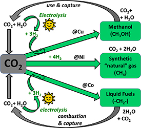
Figure 17. Illustration of how the cycle can be closed, with captured CO2 serving as a feedstock, together with green H2, to produce fuels and chemicals.
Download figure:
Standard image High-resolution imageNew catalysts are indispensable to allow this type of chemical conversion. Catalyst development for the fossil-based economy has taken decades and often relied on trial and error. However, designing catalysts to hydrogenate CO2 poses specific challenges. The first one is that it is challenging to activate the stable CO2 molecule at relatively low temperatures. Furthermore, the process is exothermic, but the change in the number of gas molecules (hence the entropy change) is unfavorable. Hence high pressures are needed to reach an equilibrium that contains a significant amount of product and hence acceptable one-pass conversions. The relatively unfavorable gas phase equilibrium might be overcome by using such a high pressure that the MeOH produced is a liquid, or by a sequential reaction, for instance, to DME, which can substitute diesel. Lastly, it is not easy to maintain catalysts' stability, as significant water concentrations are generated, inherently making supported catalysts less stable [225, 226].
Metal NPs are typically the active phase in supported catalysts. They are not freestanding but anchored on a stable support (mostly high surface area oxides) to confer thermal and mechanical stability to the system, facilitate handling, and packing the reactor and hence adequate mass and flows, and even often generate the metal NPs in the first place. A nice overview of some of the catalysts most commonly studied in the literature for the use of hydrogen to convert CO2–MeOH is given in figure 18 [227]. The most studied is the combination of Cu–ZnO–Al2O3, which is also the commercial catalyst for the present-day industrial MeOH production from synthesis gas ('syngas,' a mixture of CO and H2 with a small amount of CO2 added). This catalyst does relatively well also for the conversion of only CO2 with H2.

Figure 18. Catalyst materials for CO2 hydrogenation to methanol, percentages based on data analysis from ca. 200 papers published 2006–2016. Data taken from [227].
Download figure:
Standard image High-resolution imageHowever, as mentioned, a specific challenge when switching to hydrogenating pure CO2 is posed by the catalyst stability, as due to the high water content, the supported Cu NPs in the catalyst become less stable, while even in a commercial process of producing MeOH from syngas, the catalyst lifetime is already relatively short (typically 4–5 years). Several strategies can be applied to increase catalyst stability, which closely relates to the structure of the catalyst. For instance, the spatial distribution of the Cu NPs over the support plays a crucial role (the more equally spaced, the more stable for a given loading) [228]. Also, the support characteristics are crucial to optimize the catalyst stability, which is influenced both by the morphology of the support [209] and by its specific surface properties and morphology [229].
An interesting role is played by so-called 'reducible' oxides, such as ZnO, ZrO2, MnO2, or CeO2. They have a strong influence on the activity and stability of the catalyst, especially in the presence of CO2 [230, 231]. They can increase the catalyst activity by about an order of magnitude (figure 19) [230–232]. ZnO is a standard component in commercial MeOH synthesis catalysts, but its role is not entirely understood despite this commercial application. Part of the ZnO is reduced to a lower valency under reaction conditions, and this reduced ZnO, or perhaps even Zn, has a strong affinity to the Cu, changing its surface properties and hence catalytic activity. Next to that, reducible oxides such as ZnO are active in CO2 conversion themselves. There seems to be a strong synergistic effect in the activation of the stable CO2 at the interface between the partially reduced oxide and the Cu NPs. Furthermore, the addition of reducible oxides such as MnO2 was recently reported to also stabilize the Cu NP catalysts during hydrogenation reactions [233].

Figure 19. Illustration of the influence of CO2 concentration in the feed and the presence of a reducible oxide on the activity of Cu-based catalysts for methanol synthesis. Reproduced from [232]. CC BY 4.0.
Download figure:
Standard image High-resolution imageUnderstanding the role of reducible oxides and the intricate interplay with the Cu metal NPs and factors such as the feed compositions is crucial but severely hampered by the difficulty of measuring structure and chemical state under reaction conditions and the fact that they strongly interact also with other components in the system such as the support. Nevertheless, it is generally believed that ZnO might not be the best component in catalysts for direct CO2 hydrogenation to MeOH, and hence finding the optimum catalyst composition, microstructure and morphology is at the moment a very active area of research.
3.1.4. DME synthesis
DME is the simplest ether. At ambient conditions, it is a colorless gas. Currently used as an aerosol propellant, it is also being strongly considered as a diesel replacement due to its high cetane value of 55 (vs. <50 for diesel) and its comparable energy density of 31.7 MJ kg−1.DME (vs. 45 MJ/kg.diesel vs. 22.7 MJ kg−1.MeOH) [234].
DME is the dehydrated form of MeOH, which proceeds via the reaction in equation (13). Acidic catalysts (e.g. γ–Al2O3, H-ZSM-5) have shown promising performance at temperatures above 200 °C and low pressure [235, 236],


Recent efforts have tried to mix both the Cu-based catalyst and acidic catalyst into a bifunctional catalyst capable of synthesizing DME directly, though the presence of water and its impact on the Cu-based catalyst persist [237, 238]. Membrane reactors with hydrophilic membranes such as zeolites are seen as an effective way to selectively remove water and drive the reaction towards DME production [239].
3.2. Industrial MeOH production
Over 90 MeOH plants, with a combined production capacity of 110 Mt.MeOH/y, are currently operational worldwide. Demand is expected to increase to 500 Mt.MeOH/y in 2050 [240]. According to Methanol Market Services Asia, spot prices currently fluctuate around 400 USD2022/t.MeOH, with futures in North America and Europe around 600 USD2022/t.MeOH due to increasing NG prices [240]. Demand in North-East Asian markets has steadily increased per annum by roughly 4 Mt.MeOH/y since 2006, increasing in tandem with coal production capacity in China [241]. By 2015, China surpassed 54% of market demand and since then has effectively set the price for MeOH globally [242, 243].
3.2.1. MeOH with syngas feedstock
Today, most plants are single-line and incorporate syngas generation into the MeOH synthesis and purification process to benefit from economies of scale. This section will cover the current approaches for syngas generation, the reactor technologies for MeOH production, and the industrial process designs, including heat/steam recovery strategies.
In order to produce MeOH at scale, plants often integrate syngas generation into a single-train process, occasionally generating other chemicals in parallel. The main approaches for syngas formation are (a) steam reforming, (b) autothermal reforming (ATR), (c) combined reforming, (d) noncatalytic partial oxidation (POX) or (e) gasification of coal/petroleum/biomass/etc.
SMR is often used for small-scale MeOH plants (<2 kt.MeOH/d) with cheap raw materials in proximity. ATR is suitable for higher capacity plants, such as a 5.2 kt.MeOH/d plant in Turkmenistan—using the SynCOR Methanol™ process by Topsoe—though capacities up to 10 kt.MeOH/d are feasible with the design [244]. Combined reforming, the SMR and ATR processes in series, is suitable for >1.5 kt.MeOH/d plants but is preferred when feedstock and/or CAPEX costs are high. Noncatalytic POX is used for special feedstocks and use cases.
Conventional (non-)associated NG, consuming roughly 1000 Nm3.NG/t.MeOH, is predominantly used in Western and Middle Eastern markets [217]. Non-conventional NG (e.g. shale gas, tight gas, and coal-bed methane) has seen growth in North America since the implementation of hydraulic fracturing in 1949 [245]. Coal is the main feedstock for large-scale MeOH plants based in China, though gasification reactors handle >100 000 Nm3.syngas/h. For all aforementioned processes, a cheap O2 source must be present [217]. The Henry Hub NG spot price has dropped from 11.52 USD2020/MBtu.NG in 2005 to 2.03 USD2020/MBtu.NG in 2020 [246], though post-COVID global inflationary pressures have seen a steep increase in raw materials across all markets.
Three main reactor designs exist on the market for low-pressure STM: adiabatic reactors, pseudo-isothermal boiling water reactors (BWRs), and gas-cooled tube reactors (GCTRs). Manufacturers include Johnson Matthey (DAVY™ converters), Haldor-Topsøe (collect-mix-distribute converter), Casale, Lurgi, Linde (spiral reactor), Halliburton, Toyo (MRF-Z®), and Mitsubishi Heavy Industries(MHI) (superconverter).
Adiabatic reactors can be classified further as quench reactors—whereby catalyst beds within a single pressurized shell are connected in series—or single-line reactors with intercooling—whereby adiabatic reactors in separately pressurized shells are connected in series. Quench reactors adopt either an axial- Advanced Reactor Concept (ARC) or radial-flow design, and cooled recycled gas from the outlet of the reactor is re-injected at given depths inside the reactor to mitigate temperature bulges. The former affords a simpler internal design at the expense of pressure drop, requiring an increased vessel diameter to compensate. The latter has a more complicated internal design, though pressure drop and fouling are more efficiently controlled. Nevertheless, single-line adiabatic reactors afford good economies-of-scale, simpler design, and are more appropriate for production capacities around 10 kt.MeOH/d [217, 247].
BWRs typically have a shell/tube design whereby the catalyst is tube-side, and the water is shell-side, with feed gas and water in a co-flow regime. High-pressure steam can then be valorized elsewhere in the process. This, however, implies additional investment due to a more complicated process design, and generally, BWRs are limited in size.
GCTRs function similarly to BWRs, though the indirect heat exchange offers better temperature control with a simpler process design [248].
Per pass conversion of syngas is kept low, resulting in 7 mol% MeOH at the outlet of conventional reactors [249]. Unreacted gas is recovered from the vapor outlet of the crude MeOH flash drum, and either recycled back into the reactor or purged to mitigate accumulation of inerts. Some of the purged gas (high H2 content) can be sent to the syngas reformer upstream as fuel. Syngas is continuously injected into the recycle loop to drive the reaction. This new syngas is referred to as make-up gas (MUG).
The specific MUG consumption, defined in kmol.MUG/t.MeOHcrude, corresponds to the amount of fresh syngas that must be injected into the recycle loop. MUG is an indication of plant efficiency and minimizes at SN = 2.05. MUG is highly dependent on the raw materials used to produce the syngas (e.g. SMR without CO2 injection possesses the highest MUG with SN = 3.0). Another valuable metric is the recycle/syngas (R/S) ratio [217, 250].
Novel reactors with membrane-based in situ removal of MeOH/H2O products have been investigated since 1996 to promote an adduct-shifted process [251]. Gallucci et al demonstrated that a zeolite membrane-based reactor consistently outperformed a traditional adiabatic reactor design in CO2 conversion and MeOH-selectivity for all process conditions explored. Further theoretical analyses confirmed these results [252, 253].
Commercial plants can be divided into two classes: conventional plants producing <3 kt.MeOH/d and mega-/giga-plants producing 5–10 kt.MeOH/d. In order to achieve high production sizes and proper economies of scale, designs must incorporate lower R/S ratios, higher per pass conversions, and lower outlet temperatures for the reactors. As of 2011, the market share for operating plants was Lurgi (27%), Johnson Matthey/Davy (25%), Haldor-Topsøe (16%), and others [254].
The Johnson Matthey/Davy LPM Process (the 1960s) combines syngas generation (via reforming or gasification), MeOH synthesis, and crude purification. Capacities <3 kt.MeOH/d are feasible. NG and recycled H2 are fed into a desulphurization unit (typically a ZnO absorbent operating at 370 °C) and a dechlorination unit if necessary. High-pressure steam (from an in-line saturator or pass out turbine downstream) is then mixed and introduced to a catalytic-rich gas pre-reformer and/or the main reformer unit. Process feed stream, also regarded as 'additional fuel' in literature, (from the vapor phase outlet of the crude MeOH flash drum) or CO2 may be added to the syngas to ensure a proper SN value. The syngas (or MUG) is then fed into the closed-loop stream of the reactor. For earlier, smaller plant designs, a quench reactor was used, and operating temperatures were between 220 °C and 280 °C. Crude MeOH and water are then condensed at around 40 °C from the recycle loop, and the MeOH is purified by two distillation columns (which remove water and by-products such as ethanol). This process design has an R/S ≈ 6.0, which can be attributed to the artificially low per pass yield required of quench reactors to avoid high-temperature bulges. Heat is recovered from the syngas and MeOH reactions and valorized as high-pressure steam for compression or reboiler duty in the distillation columns. A redesign was proposed in the 1990s, impacting the syngas generation primarily by integrating the advanced gas-heated reformer concept, allowing for feedstocks containing up to 25 v%.CO2 [217].
The Lurgi Conventional Process (the 1970s) is very similar to the aforementioned design, with capacities reaching 3 kt.MeOH/d. All different forms of syngas generation are accommodated, and typically an O2 source is required. The only significant deviations are the use of a proprietary isothermal reactor and the recovery of the high-pressure steam that it generates. Byproduct formation is lower, and catalyst lifetime and STY are higher.
The Haldor-Topsøe Process distinguishes itself by the use of proprietary catalysts and designs primarily for NG reforming. This process also implements single-line adiabatic reactors with intercooling. Such a design is appropriate for any plant size up to 10 kt.MeOH/d.
The Mitsubishi Heavy Industries Process distinguishes itself by its proprietary super converter (isothermal) reactor. The maximum temperature inside the reactor is 260 °C [217, 255].
The Lurgi Mega-/Giga-Methanol Processes are meant for >3 kt.MeOH/d plants and may exceed 10 kt.MeOH/d by increasing operating pressure, though this capacity is heavily limited by equipment sizing. ATR with O2 is used to achieve the increased syngas requirements. To achieve the proper SN value, a PSA is implemented to recover H2 from the recycle loop of the MeOH reactor. Both processes are characterized by a BWR and GCTR in series with the hot product stream of the BWR used to heat the feed stream of the GCTR further driving the equilibrium towards MeOH production and allowing for a higher pass conversion yield for the process [256]. Other large-capacity process designs (Haldor-Topsøe, Davy, Toyo, Casale) typically incorporate combined reformation to achieve the necessary capacity, and the reactors for MeOH synthesis are often organized in series (rather than in parallel) with intercooling to mitigate overheating, though notable exceptions include the Lurgi process designs with two BWRs trains in parallel [217, 257].
3.2.2. MeOH with CO2/H2 feedstock
As previously mentioned, the CTM process is quite similar to the STM process, where MUG is now a CO2/H2 mixture as opposed to a syngas. Examples such as Lurgi's CTM process, the CAMERE process, and the Carbon Recycling International plant in Iceland all produce MeOH at pilot-/industrial-scale [217]. The presence of water during the reaction poses a considerable threat to Cu-based catalysts. Membrane reactors show promise as a means of in situ removal of water, though increased costs related to sweep gas processing must be considered.
Utilizing the Gibbs and plug-flow reactors in Aspen Plus, Cui and Kær demonstrated that a single-bed CTM adiabatic reactor achieved an outlet equilibrium temperature of <282 °C, which is comparable to current operating temperatures (220 °C–280 °C) for STM adiabatic reactors that implement lozenge quenching. However, modeling reflects the actuality of the global market, with BWRs exhibiting greater performance—despite elevated CAPEX—and appropriate applicability in large-scale production [258].
The current limitation of CTM is the prohibitive costs of captured CO2 and green H2. According to the International Energy Agency (IEA), CO2 captured directly from hard-to-abate sectors (steel, cement, and power) ranges between 40 and 120 USD2019/t.CO2, whereas direct air capture (DAC) ranges from 134 to 342 USD2019/t.CO2 [259]. H2 via electrolysis also shows a wide levelized cost basis depending on initial conditions, ranging from 1760 to 10 690 USD2021/t.H2 [260]. Considering the best-case scenario, where CO2 is captured from industrial emitters and H2 is produced from alkaline electrolysis, a feedstock cost of 452 USD t−1.MeOH is only valid for a 100 MW.H2 capacity at 60% utilization and 20 USD MWh−1 corresponding to a 0.15 kt.MeOH/d production capacity. Assuming CAPEX costs around 100–200 USD t−1.MeOH (50%–60% of MeOH spot price pre-COVID), 2022 production costs range between 200 and 300 USD t−1.MeOH (figure 20). Such a conclusion outlines that the CTM process can approach economic feasibility under the following conditions: (a) production plants are located near cheap and plentiful renewable energy sources, (b) a global restriction on coal as a feedstock is implemented and (c) consumers accept a premium for an environmentally-responsible product.

Figure 20. Global MeOH spot and future prices (Source: MMSA). Reproduced with permission from [242]. © 2011–2022 MMSA www.methanolmsa.com/.
Download figure:
Standard image High-resolution image3.3. Recent European initiatives in e-MeOH and e-DME
Given Europe's strong push to reduce 2030 carbon emissions to at least 55% below 1990 levels, to promote green initiatives like an H2-based economy derived from excess renewable energy, and to transition hard-to-abate sectors like Europe's steelmaking industry, the European Commission has invested heavily in several R&D projects exploring promising e-fuels like e-MeOH and e-DME.
The METHASOL project, funded under H2020-EU.3.3.2 with Grant No. 101022649, will close in December 2024. The METHASOL project aims to produce MeOH through a sustainable and cost-effective process based on artificial photosynthesis, with a solar-to-MeOH energy conversion efficiency of 5%. This technology is based on a MOF for CO2 reduction and graphitic carbon nitride for O2 evolution [261].
The PROMET-H2 project, funded under H2020-EU.2.1.2 and H2020-EU.2.1.3 with Grant No. 862253, will close in March 2023. The project aims to develop a hydraulic pressurized PEM electrolyzer with 500–750 €/kW in CAPEX and comparable performance to state-of-the-art technology without compromising performance and durability. These innovations will be implemented in a 25 kWel stack coupled with a MeOH production pilot plant [262].
The FReSMe project, funded under H2020-EU.3.3.2 with Grant No. 727504, closed in June 2021. A 1.2 t.MeOH/d demonstrator pilot, with an 800 m3 h−1 feed of blast furnace gas and renewable hydrogen, was executed. The research was also conducted on Cu/perovskite catalysts, whereby two catalysts were identified with higher selectivity for CTM than metallic Cu [263, 264].
The CirclEnergy project, funded under H2020-EU.2.1, H2020-EU.2.3, and H2020-EU.3 with Grant No. 848757, closed in June 2021. Based on Carbon Recycling International's Vulcanol® emissions-to-liquid production plant in Iceland, the project aimed to scale up the technology, identify key economic hubs, and attract investment. Tests at the George Olah (GO) plant were halted due to COVID-19, plant design advanced, culminating in the announcement of a commercial e-MeOH plant in Norway in collaboration with Statkraft and Finnfjord AS. In addition, a provisional patent for a reactor design capable of following renewable energy load has been submitted at USPTO (Application No. 62965605) [265].
The MefCO2 project, funded under H2020-EU.2.1.5.3 with Grant No. 637016, closed in June 2019. A 1 t.MeOH/d demonstrator pilot—comprised of a 1.5 t.CO2/d capture unit and a 600 kWel PEM electrolyzer—was successfully executed on Rheinisch-Westfälisches Elektrizitätswerk (RWE)'s lignite-fired power plant in Germany at TRL 6 with conversion efficiencies over 97% under static and dynamic operation in response to local renewable energy supply. Over 60 novel catalysts—based on commercial Cu/ZnO/Al2O3—were designed, with patent GB1701382.2 pending approval [266].
The FASTWATER project, funded under H2020-EU.3.4 with Grant No. 860251, will close in May 2024. The project will develop and commercialize universal, scalable retrofit kits, medium-speed, and high-speed MeOH engines. Demonstrations include a harbor tug, a pilot boat, a coast guard vessel, and a river cruiser. The complete logistical chain will be explored, from renewable MeOH production to ship bunkering, work with regulatory agencies to simplify procedures, and training programs for personnel [267].
The EMPOWER project, funded under H2020-EU.3.3.8.1 with Grant No. 875081, will close in December 2022. The project aims to develop and demonstrate a MeOH-fuelled 5 kWel combined heat and power (CHP) system based on high-temperature PEM fuel cell (HTPEMFC) technology. An aqueous phase reformer for MeOH pre-reforming is integrated into the process, valorizing waste heat from the HTPEMFC and achieving reforming efficiency >95%. Accelerated testing coupled to the energy system of a detached house will be conducted over six months for >2000 h [268].
The HyMethShip project, funded under H2020-EU.3.4 with Grant No. 768945, will close in December 2021. The project aims to demonstrate a 2 MW engine meant for marine applications. Emissions reductions include CO2 (>97%), SOx and particulate matter (undetectable), and NOx (>80%). Stored MeOH is reformed in a membrane reactor with novel ceramic membranes, whereby the CO2 is liquified and stored onboard while the H2 is sent to the ship engine for internal combustion. This CO2 is then reused onshore to produce the e-MeOH fuel again [269].
The C2FUEL project, funded under H2020-EU.3.3.2 with Grant No. 838014, will close in May 2023. The project aims to demonstrate at TRL6 the entire value chain of DME production, from the CO2 capture of blast furnace gas and generation of H2 via high-temperature electrolysis to DME production via a membrane reactor and its direct use in an internal combustion engine. Activities of the project include catalyst development, modeling of the processes including the membrane reactor by Poto et al, and a demonstrator pilot to be operated for over 4000 h on the DK6 combined cycle power plant in Dunkerque, France. FA catalysis is also under investigation, and an FA Genset will be operated at the Dunkerque harbor [270, 271].
The CO2Fokus project, funded under H2020-EU.3.3.2 with Grant No. 838061, will close in December 2022. The project develops 3D-printed, modular, mobile catalytic prototype reactors that produce DME using CO2 from industrial emitters. The H2 will be generated from solid oxide cells operating in the electrolysis mode. The entire system will be evaluated for operational flexibility in an industrial environment [272].
4. LOHCs
The pioneering work of Taube et al [273], Pez et al [274], Clot et al [275], Hodoshima et al [276], and others covered in recent reviews [28, 277–279], introduced the idea of using organic hydrogen carriers, i.e. cyclic arenes, and provide the benchmark for further developments of new materials to store and transport hydrogen. There is a resurgence in interest in using LOHCs for applications beyond onboard storage for fuel cell electric vehicles (FCEVs) due to the potential of using existing infrastructure to transport and store hydrogen at ambient pressures and temperatures. Large-scale (and long-duration) energy storage in chemical bonds is essential for a wide range of applications ranging from emergency backup power for critical infrastructure to the storage and transport of energy derived from intermittent renewable resources [280]. Conventional LOHCs are seeing growing utilization in a range of applications. Chiyoda will utilize MCH to import hydrogen from Brunei to Japan as part of a project for an international supply chain [281]. Hydrogenious is using H18-DBT as a hydrogen carrier for fuel cell powered propulsion in maritime shipping on MW scales [282]. While these approaches using LOHCs provide an opportunity to use existing infrastructure, the round-trip efficiency suffers from the high energy input required to release the hydrogen, ΔH0 (dehyd) > 60 kJ mol−1 H2. Equation (14) provides an estimate of the temperature required to achieve 1 bar pressure from a hydrogen storage material,

There have been recent efforts to discover alternate LOHCs that provide a lower enthalpy of hydrogen release to address some of these challenges. Heteroatoms or electron-donating groups attached to aromatic rings provide an approach to decrease ΔH0 and the temperature to achieve 1 bar hydrogen. For example, recent work has shown that alkali metal salts of phenol reduce the ΔH0 (dehydr) relative to phenol lowering the required temperature to release hydrogen [283]. Table 7 provides an overview of thermodynamic properties of common LOHCs.
Table 7. Thermodynamic properties of representative LOHCs.
| ΔH0 (kJ mol−1) | ΔS0
|
T (H2 1 bar) | Density H2 (wt.%) | |
|---|---|---|---|---|
| MCH (g) | 68.3 | 118.7 | 302 | 6.2 |
| DBT (l) | 65.4 | 120 | 269 | 6.2 |
| NEC (l) | 53.2 | 117.4 | 180 | 5.8 |
| PhOM (l) | 60.7 | 125 | 212 | 4.1 |
| MeOH (+H2O) | 43.6 | 136.2 | 47 | 12.5 |
| EtOH (g) | 11.3 | 42.4 | −6.5 | 4.4 |
| EtOH (l) | 35.9 | 100.5 | 84 | 4.4 |
| BDO (g) | 31 | 96.5 | 48 | 4.5 |
| BDO (l) | 43.2 | 117.7 | 94 | 4.5 |
| NH3 (liq) | 30.6 | 60 | 237 | 17.8 |
| FA (g) | −14.9 | 95.8 | −429 | 4.4 |
| FA (l) | 31.6 | 212.6 | −124 | 4.4 |
| FS (aq) | 20 | 60 | 60.3 | 7–29 |
a Calculated from available NIST data (www.nist.gov). b Defined as: (ΔH/ΔS)—273 K when ΔG = 0. c Calculated from [284]. d Reproduced from [281]. e Reproduced from [285].NEC = N-ethyl carbazole, BDO = butane diol, FA = formic acid, FS = formate salts.
To address some of these challenges there have been recent efforts to discover alternate LOHCs that provide a lower enthalpy of hydrogen release. Heteroatoms or electron donating groups attached to aromatic rings provide an approach to decrease ΔH0 and the temperature to achieve 1 bar hydrogen. For example, recent work has shown that alkali metal salts of phenol (ArOM, e.g. M=Na+) reduce the ΔH0 (dehydr) relative to phenol lowering the required temperature to release hydrogen [286].
Strategies for increasing entropy to decrease T1bar provide a different challenge. Because there is little difference in the entropy, S0, of the cyclo-alkane (ArH2) and the corresponding arene (Ar), the increase in entropy for dehydrogenation is set by the entropy of an H2 molecule, ca. 131 J K−1 mol−1 (equation (15)),

One example of LOHC that can increase entropic term is FA as it decomposes to release two gas molecules, H2 and CO2, resulting in ΔS0 = 215 J K−1 mol−1, and a corresponding ΔH0 31 kJ mol−1 H2 [287, 288]. However, since ΔG0 is −33 kJ mol−1 H2, FA is generally used as a one-way H2 carrier. Carbon dioxide could be capture and the FA can be regenerated by a series of chemical manipulations.
Ammonia, discussed earlier in this review, provides an example of a liquid hydrogen carrier that is thermodynamically favored to release hydrogen at ambient temperatures, ΔS0 ca. 66 J K−1 mol−1 (and ΔH0 ca. 30 kJ mol−1 H2) but requires higher temperatures due to kinetic limitations.
Another approach to modify ΔS0 is provided by the dehydrogenative coupling of two moles of ethanol to form two moles of H2 and ethyl acetate (EtOAc) (equation (16)),

In the liquid phase, ΔS0 is reduced to 100 J K−1 mol−1, with a corresponding decrease in enthalpy of 36 kJ mol−1 H2. This combination results in a temperature of ca. 84 °C to reach 1 bar of H2. However, as the b.p. of EtOH is 78 °C, 1 bar of H2 is not achievable in the liquid phase. Ethanol provides an interesting example of a large change in thermodynamic properties transition from the liquid phase to the as phase, i.e. ΔH0 decrease from 36 kJ mol−1 H2 to 11 kJ mol−1 H2 and ΔS0 decreases from 110 J K−1 mol−1 to 42 J K−1 mol−1 with a corresponding H2 equilibrium pressure >1 bar at the boiling point. A recent analysis showed that a single homogeneous molecular catalyst, RuMACHO, could be used to enable both H2 release from EtOH and H2 uptake by EtOAc to regenerate EtOH at temperatures <70 °C [289].
Another approach that receives increased attention is hydrogen storage in aqueous solutions of formate. Yoel Sasson was one of the first to describe the reaction of water and formate to yield hydrogen and the corresponding bicarbonate [290]. He observed kinetic isotope effects (KIEs) on the rates of H2 release at 35 °C in the presence of a Pd/C catalyst and found that CH bond scission in formate and OH bond scission in water are involved in the RLS. In subsequent studies, Su and co-workers demonstrated hydrogen uptake by bicarbonate salts under moderate pressure and temperature conditions and the subsequent cycling using sodium, potassium, and ammonium formate [291]. Recently, DFT studies were used to investigate the mechanism of the reversible reaction [292]. The authors proposed dissociation of formate on the Pd surface to a bound carbon dioxide (CO2*) and hydrogen (H*). Subsequent attack by hydroxide on the CO2* generates the bicarbonate, and H* reacts with the hydrogen from water to yield H2. The work was consistent with the reported KIE, noting that both CH and OH bond scissions are important in the RLS [293].
It is notable that the release of hydrogen from FA is greatly enhanced with the addition of a formate salt. Chen and Mavrikakis recently published a DFT study suggesting that hydrogen bonding of FA and a co-catalyst, formate salt, on the metal surface enables the release of H2 [294]. Over the past few years, numerous publications have focused on the potential of using aqueous formate salts to store and transport hydrogen [287, 288, 295, 296]. While formate salts do not provide the same volumetric density of hydrogen as FA, they still have some unique advantages over FA: (a) ½ of the hydrogen comes from water so one can transport the formate salt in solid-state and add water at location where hydrogen is needed, (b) there are no volatile impurities, (c) formate salts yield H2 and bicarbonate instead of H2 and CO2, minimizing need for gas–gas separations, and (d) the free energy of reaction near-zero kJ mol−1 enables both release and uptake of hydrogen under low pressures and moderate temperatures, whereas FA is energy-intensive to regenerate (equations (17) and (18)),


Additionally, formate salts and the corresponding bicarbonate products are non-flammable, non-acidic and non-toxic, and can be transported as a solid or in aqueous media using existing infrastructure. Some work discussed the benefit of defining storage, deliverable, and usable hydrogen storage capacity. Storage capacity is defined as the amount of H2/L of formate salt; deliverable capacity is limited by the solubility of formate salt at ambient temperature; usable density is limited by the solubility of the resulting bicarbonate salt at the temperature of the reactor [296]. Visual representation of these terms is provided in figure 21.
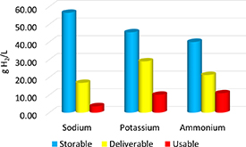
Figure 21. Visual representation of capacities, grams H2/liter, of formate salts. Storable capacity is limited by the theoretical density of hydrogen in the solid-state, deliverable capacity is limited by the solubility of the formate in water at 25 °C, usable capacity is limited by the solubility of the product, bicarbonate, in water at 60 °C.
Download figure:
Standard image High-resolution imageWhile metallic palladium NPs on carbon supports (Pd/C) appear to provide the most rapid rates of H2 release, a challenge appears to be the subsequent deactivation of the Pd/C catalysts [297]. One interesting observation is that the Pd/C catalyst appears to deactivate after the release of H2, whereas the hydrogenation reaction does not deactivate the catalyst. Therefore, in batch reactors, the Pd/C catalyst needs to be reactivated after each H2 release cycle. Fortunately, washing with copious quantities of water is suitable for the re-activation of the Pd/C catalyst. This may not be acceptable for all industrial practices, therefore, further work is needed to understand and prevent deactivation [291, 293, 298].
Given all the advantages of formate and the fact that the catalyzed hydrogen release rates using Pd/C are suitable for energy storage application, it would be advantageous to understand and mitigate the deactivation pathway. In a recent contribution, various potential modes of deactivation, including (a) CO poisoning, (b) change in the oxidation state or active phase of the metal, (c) growth of Pd NPs, and (d) blocking of catalyst pores by either reactants or products, have been discussed [296].
Carbon monoxide poisoning was ruled unlikely since washing with water is reported to reactivate the catalyst. CO binds strongly to metals and generally requires heating to high temperatures to release CO. Some studies report of a change in the oxidation state of the starting catalyst from a mixed Pd(II)/Pd(0) to a reduced Pd(0) species or formation of a Pd hydride phase under operating conditions. However, this warrants deeper consideration since (a) one can start with hydrogenation of bicarbonate where the Pd(II)/Pd(0) 'fresh' catalyst is reduced to Pd(0) before following through with the cycle of H2 release where the catalyst behaves as fully activated and (b) washing with water to activate the Pd/C after H2 release does not change the oxidation state where any Pd(II) is observed. TEM performed on the catalysts before and after the H2 release reaction does not show any significant change in the size of the Pd NPs. Moreover, leaching is unlikely as washing with copious quantities of water regenerates the catalytic activity.
The possibility of blocking access to the Pd NP has been reported for the dehydrogenation reaction of FA, where formate salts are often added to the aqueous FA solutions to enhance the rates of H2 release [285]. In the experiments starting with aqueous solutions of formate salts, the only observable species are formate, bicarbonate, hydrogen, and CO2. Given the difficulty to explain the deactivation of Pd/C after H2 release from aqueous formate, determination of the relative binding energies of key intermediates to the metal NP could provide further insight.
Assuming the intermediates are part of the reaction network, some may react more strongly with the Pd surface and prevent forward reactions, thereby contributing to the observed deactivation of the catalyst material. To test this surface poisoning hypothesis, binding enthalpies of HCOOH, HCOO−, HCO3 − and CO were evaluated using hybrid quantum chemical computations accounting for the role of the solution phase [299, 300].
Table 8 tabulates the binding enthalpies of these key intermediates in 1 M HCOONa solution and gas phase to the Pd (111) catalyst. While HCOOH has a weak interaction with Pd, HCOO− and HCO3 − tend to stably bind via a Pd–O bidentate interaction. The presence of these negatively charged species, including HCOO− and HCO3 − at the Pd surface undergoing dehydrogenation or hydrogenation reactions can significantly impact the distribution of solvent species near the Pd interface and can play a distinct role in modulating the concentration of H+ and Na+ ions at the metal-solvent interface in FA-formate mixtures. This additional component of solvent interaction is what tunes the binding strength of these intermediates on the Pd surface, as can be rationalized by the lowered binding enthalpies in 1 M HCOONa relative to the gas phase. This effect is compounded at higher surface coverages wherein the competitive binding of these intermediates can alter the binding mode via lateral adsorbate interactions as well as modify the local cationic distribution/pH at the metal-liquid interface, consequently affecting the kinetics of formate dehydrogenation and bicarbonate hydrogenation.
Table 8. Comparison of the computed binding enthalpies (in eV) of key intermediates HCOOH, HCOO, HCO3, and CO on Pd (111) in 1 M HCOONa and gas phase. More negative values denote stronger binding to Pd.
| Reaction intermediate | HCOOH | HCOO | HCO3 | CO |
|---|---|---|---|---|
| Aqueous phase (1 M HCOONa) | 0.07 | −1.06 | −1.89 | −1.94 |
| Gas phase | −0.30 | −2.61 | −2.55 | −1.73 |
Considering the reversibility of dehydrogenation and under reaction conditions that avoid the formation of CO2, hydrogen storage based on the formate-bicarbonate cycle is a carbon-neutral process. It can be regarded even as carbon-negative if CO2 is captured and used to make either formate or bicarbonate. Like other LOHCs, the reaction to convert the hydrogen depleted carrier species (bicarbonate) back to the hydrogen 'charged' carrier species (formate) with molecular hydrogen is favorable under moderate temperatures and pressures. An advantage compared to other LOHCs is the enthalpy for hydrogenation (ΔH = 20 kJ mol−1 H2) which is in a desirable range to minimize thermal management upon hydrogenation. This enthalpy value is significantly lower than for cyclic hydrocarbons, MCH (ΔH0 = 68 kJ mol−1 H2), ethyl carbazole (ΔH0 = 50 kJ mol−1 H2,) and even EtOH (ΔH0 = 39 kJ mol−1 H2) [289].
An additional alternative to consider is the possibility of regenerating formate electrocatalytically, bypassing the need for forming molecular hydrogen in a discreet step (figure 22).

Figure 22. Proposed formate/bicarbonate cycle, including electrochemical regeneration of formate salt without the use of molecular hydrogen.
Download figure:
Standard image High-resolution image
By performing electrolysis of CO2 instead of electrolysis of water, it is possible to combine two steps into one [301].
5. Outlook
With the growing utilization of renewable energy sources ranging from wind to solar, there is a growing need to store intermittently generated energy for times when energy demand is greatest. LOHCs are made from earth-abundant materials that can be readily regenerated and used over several cycles. As such, LOHCs, described above, as well as ammonia, provide a geographically agnostic opportunity to store energy at large scales on time scales ranging from days to several months to couple the gap between energy production and energy demand when salt caverns or pipelines are not readily available. According to the US DOE Hydrogen Program Plan [302], the utility projection of pipelines (∼1000 tonnes d−1) are expected to be mostly in regions where there is significant demand that is stable for a long duration of 15–30 years. However, LOHC (∼1000 tonnes d−1) are expected to be utilized for applications where the hydrogen demand is substantial, but not stable enough to warrant pipeline construction and preferably enables need based onsite storage for extended, intermittent time periods at the site of utilization [303, 304]. For round trip carriers, research will continue on the development of catalysts to provide high selectivity and durability to enable multiple cycles of release and uptake of hydrogen. For one-way carriers such as ammonia, research will continue to develop catalysts that use strategies to activate stable N2 molecules at lower temperatures to take advantage of the favorable thermodynamics for ammonia production. A simple prediction of the best future liquid hydrogen carrier system is very difficult. Depending on the specific applications and the fundamental chemical, physical and technological restrictions of the different liquid carriers, only their flexible utilization seems to be the most promising approach for the implementation of liquid hydrogen carriers. This is well illustrated by noting the rising interest in the development of LOHCs by commercial interests around the World for hydrogen storage and hydrogen transport for applications beyond FCEVs. One of the earliest suggestions involved the use of the formate/bicarbonate cycle by researchers at the Hebrew University for dispatchable energy storage. More recent examples include Chiyoda in Japan developing processes to use toluene; Hydrogenious is commercializing benzyl toluene derivatives; Dutch Energy Solutions and OCO Chem in the USA are developing FA to store for H2 generators; and Hynertech in China is developing LOHCs for multiple applications, providing several examples of how far LOHCs have come in recent years.
Acknowledgments
This paper was realized within the framework of the Hydrogen Technology Collaboration Programme (TCP) of the International Energy Agency (IEA) in Task 40 'Energy storage and conversion based on hydrogen'.
T H U acknowledges the funding provided by Deutsche Forschungsgemeinschaft (DFG) (Grant WE 2884/2-1).
T A, K G, J K, S A A, B C W acknowledge support from the Hydrogen Materials—Advanced Research Consortium (HyMARC), established as part of the Energy Materials Network under the U.S. Department of Energy, Office of Energy Efficiency and Renewable Energy, Hydrogen and Fuel Cell Technologies Office.
*This work was performed under the auspices of the U.S. Department of Energy by Lawrence Livermore National Laboratory under contract DE-AC52-07NA27344.
*Pacific Northwest National Laboratory is operated by Battelle for the US Department of Energy under Contract DE-AC05-76RL01830.
P C and W G acknowledge the support provided by the National Natural Science Foundation of China (Grant Nos. 21988101, 21633011 and 22109158).
T R J acknowledges funding from the independent research fund Denmark for technology and production via the projects Solid-State Magnesium Batteries—SOS-MagBat (9041-00226B) and Calcium Metal Battery—CaMBat (DFF-0217-00327B), and the Danish Ministry of Higher Education and Science through the SMART Lighthouse.
P E J and P N acknowledges funding from the NWO materials for sustainability (739.017.009) Grant, as well as the NWO ECHO (712.015.005) Grant.
Data availability statement
No new data were created or analyzed in this study.