
Abstract
In order to meet the requirements of high reliability, long-lifetime and lightweight in a new generation of aerospace, aviation, high-speed train, and energy power equipment, integrated components are urgently needed to replace traditional multi-piece, welded components. The applications of integrated components involve in a series of large-size, complex-shaped, high-performance components made of difficult-to-deform materials, which present a huge challenge for forming ultra-large size integrated components. In this paper, the developments and perspectives of several extreme forming technologies are reviewed, including the sheet hydroforming of ultra-large curved components, dieless hydroforming of ellipsoidal shells, radial-axial ring rolling of rings, in situ manufacturing process of flanges, and local isothermal forging of titanium alloy components. The principle and processes for controlling deformation are briefly illustrated. The forming of typical ultra-large size integrated components and industrial applications are introduced, such as the high strength aluminum alloy, 3 m in diameter, integrated tank dome first formed by using a sheet blank with a thickness the same as the final component, and a 16 m diameter, integrated steel ring rolled by using a single billet. The trends for extreme forming of ultra-large size integrated components are discussed with a goal of providing ideas and fundamental guidance for the further development of new forming processes for extreme-size integrated components in the future.
Export citation and abstract BibTeX RIS

Original content from this work may be used under the terms of the Creative Commons Attribution 3.0 licence. Any further distribution of this work must maintain attribution to the author(s) and the title of the work, journal citation and DOI.
1. Introduction
In order to meet the requirements of high reliability, long lifetime and lightweight in a new generation of aerospace, aviation, high-speed train, and energy power equipment, there is a huge need for ultra-large size components with high performance. Except for traditional multi-piece welded components, integrated structural components are becoming the ideal loading structures, which are the first design choice if the integrated components could be successfully formed. As a result of structural integration, the size of these integrated components becomes ultra large, e.g. the tank dome and connecting ring of heavy launch vehicle with body diameter up to 10 m [1], and the shape of these integrated structural components is very complex. Some local small features often need to be formed on the ultra-large size components. That is to say, the application of integrated structural components results in the appearance of a series of large-size, complex-shaped and high performance components, including thin-walled curved surface components, ellipsoidal shells, rings with complex sections, forged frames, etc.
In addition, the materials applied have expanded to lightweight alloys, such as aluminum alloy, magnesium alloy, titanium alloy and new materials with high strength-to-weight ratio [2, 3]. Among them, aluminum alloy is the main structural material used for aerospace and aviation equipment, such as launch vehicles and aircraft. The percentage of aluminum alloy used in a launch vehicle structure is about 80% and in civil aircraft is more than 50%. Titanium alloys are widely used in engines and aerospace industries due to the high strength, excellent corrosion resistance and high temperature performance. The amount of titanium alloys used in the F-22 and F-35 aircraft are 39% and 27%, respectively [4–6].
In order to ensure long-term, stable service in severe working conditions, such as heavy loads, varying loads, impacts, high or low temperatures, corrosion, radiation, etc, integrated structures with high dimensional accuracy are required. For example, the dimensional accuracy of the integral intake of the new generation fighter aircraft is required to be less than 0.25 mm to ensure its stealth and aerodynamic performance. It should be noted that the dimensional accuracy has to be guaranteed in the forming process because subsequent machining cannot be conducted on the thin-walled, curved surface components. Moreover, the critical requirements of microstructure and performance also need to be satisfied.
Due to the critical requirements for the ultra-large size integrated components, three kinds of problems are encountered in the forming process:
- (1)The materials are very difficult to deform due to high deformation resistance, low plasticity and the easy occurrence of rupture.
- (2)The shapes are very complex, due to significant changes in curvature radius, irregular cross-sections, and small local features. Sometimes, the thickness is extremely thin or the thickness-to-diameter ratio is less than 2%, which easily results in simultaneous wrinkling and rupture.
- (3)The performance requirements are very high, i.e. high dimensional accuracy, mechanical properties, and microstructure are all required.
It is well known that the traditional forming processes, such as stamping, spinning, superplastic forming, forging, etc, have been applied in manufacturing various types of components with small or middle sizes in automobile, aerospace, and 3C industries. However, a great challenge is caused in forming the ultra-large size integrated components, especially while the complex-shaped and hard-to-deformation materials are coupled with the ultra-large size, which exceeds the forming deformation limits. Therefore, several advanced precision forming processes have been developed to address this challenge, including the sheet hydroforming of curved components, dieless hydroforming of ellipsoidal shells, radial-axial ring rolling (RARR) of rings, in situ manufacturing process of flanges and isothermal forging of titanium alloy components. This paper will review the ideas, fundamentals, processes and industrial applications of these precision forming processes of ultra-large size integrated components.
2. Sheet hydroforming of ultra-large curved components
2.1. Principle of sheet hydroforming
Sheet hydroforming is an advanced manufacturing technology for forming ultra-large thin-walled curved components, in which liquid mediums, such as oil, water and special fluid medium are used to replace one half of the rigid die in the drawing or bulging processes. The metal sheets are jointly formed by the punch and fluid pressure. Some complex shaped curved surface components can be formed by controlling the fluid pressure. According to the role of liquid mediums, sheet hydroforming is mainly divided into two categories: hydro deep drawing and fluid punch drawing, as shown in figure 1 [7].

Figure 1. Principle of sheet hydroforming: (a) hydro deep drawing and (b) fluid punch drawing.
Download figure:
Standard image High-resolution imageHydro deep drawing is a process wherein the female rigid die is replaced by a liquid medium. The final component geometry is defined by the geometry of the punch [8]. Compared with traditional deep drawing, formability and dimensional accuracy can be improved due to the changes in the stress state and frictional behavior, as shown in figure 2.
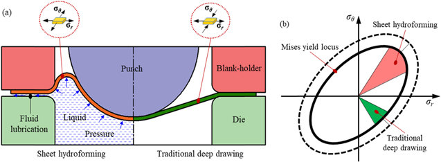
Figure 2. The comparison between sheet hydroforming and traditional deep drawing: (a) the changes in stress state and frictional behavior and (b) von Mises yield locus.
Download figure:
Standard image High-resolution imageThe sheet deformation is carried out in a biaxial stress state and accompanied with decreasing friction force by fluid lubrication between the blank and die. The drawing ratio of the 0.7 mm thick and 50 mm diameter stainless steel cylinder could be up to 3.4, which is 47.8% higher than that formed by traditional deep drawing [9]. Moreover, the forming of complex-shaped components can be completed in one process due to the increase in the forming limit, the multi-step forming, and related tooling and dies that are not needed. There is also no need for high matching with an upper die or punch and lower female die, so the production costs can be greatly reduced.
Fluid punch drawing, also called sheet high pressure forming, is a process wherein the sheet is formed by an active fluid pressure [10]. The traditional rigid punch or the male die is replaced by the liquid mediums, and the final component geometry is decided by the defined geometry of the female die. At the beginning of this process, the material is drawn freely into the female die. After the component is almost completely formed, it is then calibrated by means of a higher internal pressure. The blank-holder force should be adjusted versus the internal pressure to avoid leaks as well as uncontrolled material flow. The main advantage is the possibility of a detailed control of fluid pressure and blank-holder force to achieve an optimal use of the formability of the materials [11]. Finally, the components with complex shape and local small round corners can be obtained [12].
2.2. Key technologies for controlling wrinkling and rapture
Wrinkling and rapture are the main defects in sheet hydroforming, as shown in figure 3, which limits further applications in various industries. Furthermore, the greatest difficulty is that the wrinkling and rapture occur simultaneously when hydroforming the ultra-large diameter thin-walled curved components with thickness to diameter ratio less than 5%. This is an international problem in the metal forming industry. Therefore, the key technologies and processing parameters of sheet hydroforming are how to avoid wrinkling and rapture.
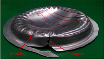
Figure 3. Typical defects of wrinkling and rapture in sheet hydroforming.
Download figure:
Standard image High-resolution imageGenerally, wrinkling and rapture can be avoided by conducting a reasonable processing window [13], which can be obtained by theoretical analysis and experiments based on the relationship of the fluid pressure and drawing displacement [14, 15]. The analytical models on the wrinkling and rapture for the hydroforming of curved surface components have been established by the combination of stress model and geometrical model [16]. The critical wrinkling pressure (pw) and rupture pressure (pr) of the ellipsoidal curved dome can be analytically calculated, which is very useful to predict the upper and lower pressures for sound components with no wrinkling and rupture, as shown in figure 4.

Figure 4. Prediction models of wrinkling and rupture pressures.
Download figure:
Standard image High-resolution imageThe wrinkling can be eliminated by the proper 'reverse bulging effect', which is mainly decided by the variation of the area with the bulging pressure [17]. In general, when the 'reverse bulging effect' is proper at a certain value of punch stroke, the magnitude of the critical wrinkling stress is increased and the circumferential compressive stress is decreased, so that the processing window of the liquid pressure and punch stroke can be obtained, as shown in figure 5.

Figure 5. Processing window of sheet hydroforming.
Download figure:
Standard image High-resolution imageObviously, the coupling effect of size and deformation is critical for hydroforming large size integrated components. As the blank size increased, the wrinkling and rapture occurred easily because of the increasing tangential compressive stress and fraction force, as shown in figure 6. In order to solve these problems, the blank-holder force and liquid pressure should be controlled within a reasonable process window.

Figure 6. Effect of blank diameter (D) to cylindrical cup diameter (D0) ratio on defects during sheet hydroforming.
Download figure:
Standard image High-resolution imageIn recent years, several advance hydroforming technologies have been developed to solve the problems of wrinkling and fracture that occur simultaneously, especially for hydroforming ultra-large thin-walled curved components, such as sheet hydroforming with double side pressure, positive radial pressure, pre-bulging and warm hydroforming.
2.2.1. Sheet hydroforming with double-sided pressure
Figure 7 shows a schematic diagram of sheet hydroforming with double-sided pressure, which was proposed to avoid suspension zone rupture and further improve the forming limit [18]. This process is suitable to form the surface curved components with diameter larger than 2 m and thickness to diameter ratio smaller than 5%. The sheet can be deformed at a reasonable stress state by controlling the ratio of double side pressure (λ = p2/p1). The stress states vary with an increase in the ratio of double-sided pressure. The forming characteristic is changed under the influence of through-thickness normal stress [19]. When the ratio is increased to 0.5–1, the biaxial stress state in the reverse bulging zone is changed to an equal tensile-compressive stress state. The problem of wrinkling and rupture is solved, and the thickness distribution is effectively improved. The position of the thickness invariant line moves along the radial direction to the bottom zones with an increase in pressure ratio, and the area of thinning zone decreases [20].

Figure 7. Principle of sheet hydroforming with double side pressure.
Download figure:
Standard image High-resolution image2.2.2. Sheet hydroforming with positive radial pressure
Figure 8 shows a schematic diagram of sheet hydroforming with positive radial pressure, which was proposed to increase radial pressure and decrease the friction force [21], so that this advanced process can be utilized to form deep cylindrical or conical components with height to diameter ratio larger than 1.0.
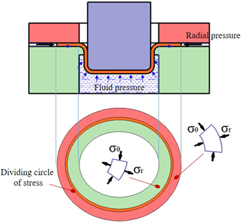
Figure 8. Principle of sheet hydroforming with positive radial pressure.
Download figure:
Standard image High-resolution imageAn obvious stress dividing circle is produced due to the addition of radial pressure, whose position moves toward the radius zones of the female die with the increase of radial pressure. Because the radial pressure can be controlled independently of the fluid pressure, an optimum forming condition can be obtained by varying the radial pressure. The limiting drawing ratio is increased due to the decreasing radial tensile stress and increasing inward flowing liquid. A 2A12 aluminum alloy cup with a drawing ratio of 2.85 was successfully formed [22]. The thickness thinning ratio decreases gradually when the radial pressure is increased, but increases after the radial pressure is increased to a large extent [23]. In this process, the wrinkling is prevented because of the increase in the tangential compressive stress [24].
2.2.3. Sheet hydroforming with pre-bulging
Sheet hydroforming with pre-bulging was developed to improve the thickness distribution and strain hardening, which is appropriate to form the surface curved components with high uniformity of thickness distribution, especially when the thickness thinning ratio is less than 10%. When the pre-bulging is used, the unsupported portion of the blank between the punch and the blank-holder is pressurized to bulge in the direction opposite to the punch displacement. The deformation is added in every zones, especially in the un-deformed zones of traditional sheet hydroforming, thus the strain hardening and thickness uniformity are increased [25, 26], as shown in figure 9. The corresponding enhancement degree is decided by the optimized pre-bulging and hydroforming parameters like pre-bulging height, shape, location and fluid pressure, etc.

Figure 9. Effect of pre-bulging shapes on thickness distribution. [26]2018 © Springer Verlag-London Ltd. With permission of Springer.
Download figure:
Standard image High-resolution imageThe local pre-bulging is utilized to control the uniform deformation and avoid rapture in integral bulging of complex curved surface components, resulting in the hardening area of the bottom of a curved surface being 68% higher than that of components without pre-bulging [27]. The tensile stresses are produced in the circumferential direction of the extended portion to release the compressive stresses. The tension forces in the radial direction are also increased by the pre-bulging pressure, the wrinkling could also be repressed [28].
2.2.4. Warm hydroforming
Warm hydroforming was developed to improve the formability of lightweight alloys at elevated temperature, as well as decrease the spring-back and residual stress. This advance forming process is suitable to form the low plasticity materials like aluminum alloy, magnesium alloy and titanium alloy. In this process, the improved formability is utilized at elevated temperature. The heated tooling and hydraulic medium are used to transport heat and mechanical force. It is well known that the formability of lightweight alloy materials is increased at elevated temperature [29]. The process parameters should be appropriately controlled to realize the warm hydroforming. The temperature, pressure and both coupled effects on performance should be firstly taken into account. The analytical models and experiments were developed to investigate the effects of process conditions such as temperature, hydraulic pressure, blank holder force and forming speed [30]. The optimal temperature distribution of the tooling could be realized by subregion heating. The drawing ability of an AZ31 magnesium alloy sheet was obviously improved, as the flat bottom cylindrical component with a drawing ratio of 3.0 was directly obtained by warm hydroforming [31]. The drawing ability of an AA5754 aluminum alloy sheet was about 100% higher than the traditional stamping methods [32].
2.3. Typical application of sheet hydroforming
Sheet hydroforming, in which one-half of a rigid tool is replaced by the liquid medium, is an alternative technology to deep drawing and stretch forming. Thin-walled curved components with a high drawing ratio and complex shape can be formed in a single step by reasonably controlling the liquid pressure. Since this innovative technology was proposed, sheet hydroforming has gradually developed into one of the key technologies for precise, highly efficient, integral forming of complex, thin-walled curved components, which are used in the manufacturing of car body panels, rocket fairings, aircraft engines and some difficult-to-deform material components. The shape of the applied components changed from the cylindrical, conical, parabolic and box to the complex surface components. The materials have expanded from carbon steel and stainless steel to aluminum alloy, magnesium alloy, nickel based super alloy, and some difficult-to-deform materials with high specific strength and high performances. The maximum size of these components was up to 3300 mm, the corresponding ratio of thickness to diameter was less than 2%. Meanwhile, the forming accuracy improved to a level of less than 0.25 mm, and good surface quality was guaranteed simultaneously [33–37].
Sheet hydroforming is used in the manufacturing of automobile components, including the body panel, the hood, roof and others. A flexible hydroforming production system was developed to produce the outer hood, inner hood, inner door and outer body side panel. The system was applied in series production. Among these automobile components, the maximum size was 2200 mm in length and 1600 mm in width [38].
In order to meet the urgent need for large-size integrated curved component of high strength aluminum alloys, a sheet hydroforming press was developed with 150 MN in drawing force and 5 m3 in volume of high pressure liquid. Its drawing force and high pressure liquid volume is 1.5 times and 10 times larger than the previous largest sheet hydroforming press made by a Germany company. The parallel synchronous control technology of a multi-supercharger was used to solve the problems associated with pressurization and transmission of large volume liquid mediums with high pressure. An aluminum alloy tank dome, 3 m in diameter, was integrally formed by this hydroforming press. The corresponding thickness to diameter ratio was less than 2%, as shown in figure 10. The new technology of sheet hydroforming with double-sided pressure was utilized to solve the problems of wrinkling and rapture occurring simultaneously. The limiting value of the thickness to diameter ratio was significantly improved in the forming process of ultra-large, thin-walled, curved components. It should be noted that this ultra-large size integrated tank dome was directly formed for the first time ever by using the sheet blank with a thickness the same as the final component. The used material of this manufacturing method was saved up to 80% compared to that used with the previous spinning and machining methods, which used a blank of about 6–8 times the thickness of the final component. The production cycle decreased form 3–6 months to 1 week, with a reduction in the manufacturing cost of 50%.
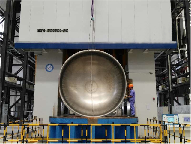
Figure 10. Aluminum alloy tank dome with 3 m in diameter and hydroforming press with 150 MN in drawing force and 5 m3 in high pressure liquid volume.
Download figure:
Standard image High-resolution image2.4. Existing problems and further development of sheet hydroforming
The existing major problems in sheet hydroforming of ultra-large size components are the need for extreme larger tonnage press and volume of high pressure liquid. Figure 11 shows the relationship of forming force and volume versus component diameter. While the 7.5 m diameter component is formed, the forming force and volume of high pressure liquid are up to 1000 MN and 80 m3, respectively. The cost of the heavy tonnage equipment is extreme high and there is a huge technical risk. In order to realize the forming of extremely large components, it is necessary to develop a new sheet hydroforming process, which can greatly reduce the forming force.

Figure 11. Relationship of forming force and liquid volume versus component diameter.
Download figure:
Standard image High-resolution image3. Dieless hydroforming of ultra-large ellipsoidal shells
3.1. Principle of dieless hydroforming
Dieless hydroforming was developed as a new technique to manufacture ultra-large closed shells without using dies. The metal plates are firstly roll-bent into the lateral petals, then assembled and welded into a pre-form polyhedron shell, which is inscribed in the ideal ellipsoidal shell. After that, the pre-form shell is filled with water and finally bulged into the described shell with internal pressure, as shown in figure 12 [39]. This method is also suitable for the forming of a spherical shell by adjusting a pre-form polyhedron structure. Compared with the traditional shell forming technology, its advantages are no need for dies and equipment for side-petal forming, avoiding the influence of welding on the shape accuracy of shells, and significantly reducing the cost of ultra-large diameter shells. Therefore, the new technique is very suitable for manufacturing ultra-large thin shells.

Figure 12. Principle of dieless hydroforming of ellipsoidal shells: (a) blanking, (b) roll-bending of petals, (c) assembling and welding into a polyhedron shell, and (d) hydro-forming. Reprinted from [40], Copyright 2015, with permission from Elsevier.
Download figure:
Standard image High-resolution image3.2. Wrinkling behavior during dieless hydroforming of ellipsoidal shells
The ellipsoidal shells have been widely used as pressure vessels, water containers, artistic buildings and launch vehicle fuel tank domes because of the small wind area, large capacity and attractive outline. The stress distribution of an ellipsoidal shell depends on the geometric shape and corresponding curvature radius under the action of certain internal pressure. The longitudinal stress is always in tensile state for any ellipsoidal shells, but the latitudinal stress varies with the axis length ratio. As seen in figure 13, there is a dividing line on the ellipsoidal shell while the axis length ratio exceeds  where the latitudinal stress changes from a tensile state to a compressive state. A strong possibility of wrinkling on the equatorial plane is caused by the compressive stress in the circumferential direction [41].
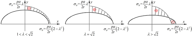
Figure 13. Relationship between latitudinal stress and axis length ratio. Reprinted from [40], Copyright 2015, with permission from Elsevier.
Download figure:
Standard image High-resolution imageExperimental research has been conducted to analyze the effect of internal pressure on the variation of shell shape and wrinkling, by hydroforming of an ellipsoidal shell with an initial axis length ratio of 1.8, as shown in figure 14. As shown, the latitudinal stress on the equatorial plane was increased as the internal pressure increased, and the wrinkling occurred when the internal pressure was 1.0 MPa. The wrinkling became severe when the internal pressure was increased to 2.2 MPa. As the axis length ratio increased, the wrinkling became more serious. When the initial axis length ratio was 2.2, the wrinkling could not be eliminated during hydroforming of the ellipsoidal shell, as shown in figure 15.
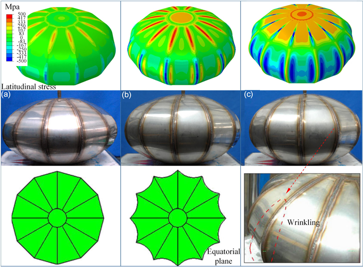
Figure 14. Latitudinal stress distribution and shape variation of the ellipsoidal shell with initial axis length ratio of 1.8: (a) initial state, (b) p = 1.0 MPa, and (c) p = 2.2 MPa. [42] 2014 © Springer-Verlag London. With permission of Springer.
Download figure:
Standard image High-resolution image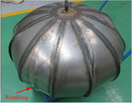
Figure 15. Severe wrinkling on ellipsoidal shell with initial axis length ratio of 2.2.
Download figure:
Standard image High-resolution image3.3. Novel dieless hydroforming of ellipsoidal shells with double generating lines
In order to manufacture the ellipsoidal shell with the axis length ratio exceeding  some works have been carried out to change the compressive stress state. One method is that the short axis was restricted by hydraulic press [43]. Another is the ellipsoidal shell was restricted in short axis direction by welding a central tube in the initial state [44]. Unfortunately, these methods were not suitable for hydroforming of the large-size ellipsoidal shells due to the limit of worktable area in hydraulic press and the instability caused by external high pressure applying on central tube.
As known, the latitudinal compressive stress existed on the ellipsoidal shell segment from the equatorial line to the dividing angle α while the axis length ratio exceeded  In order to avoid the latitudinal compressive stress, an ellipsoidal shell with double generating lines was designed as the pre-form shell [40]. In this combined structure ellipsoidal shell, the ellipsoidal shell segment had an axis length ratio exceeding
  and strong possibility of wrinkling occurrence was replaced by another ellipsoidal shell segment with an axis length ratio of less than
  as shown in figure 16.
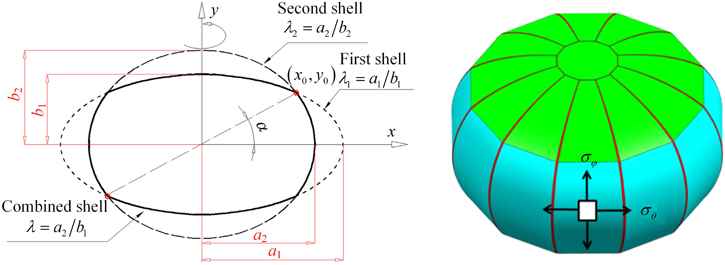
Figure 16. Structure of the ellipsoidal shell with double generating lines. Reprinted from [40], Copyright 2015, with permission from Elsevier.
Download figure:
Standard image High-resolution imageThe combined ellipsoidal shell was composed of two ellipsoidal shells with different axis length ratios. The axis length ratio of the first ellipsoidal shell (λ1) was larger than  and that of the second ellipsoidal shell (λ2) was less than
  The dividing angle of the combined ellipsoidal shell was that of latitudinal tension and compression stress for the first ellipsoidal shell. For the combined ellipsoidal shell with double generating lines, the optimization design on the polyhedron preform shell was very important. The initial axis length ratio of preform shell inscribed in the ideal ellipsoidal shell had to be larger than that of a sound ellipsoidal shell.
The needed ellipsoidal shell could easily be obtained by the structural design of the pre-form shell [45]. Meanwhile, the forming accuracy depended on the welding assembly process and subsequent hydroforming, the welding quality should ensure the enough plastic deformation of dihedral angle [46]. Experimental research was conducted on the ellipsoidal shells of double generating lines with an axis length ratio of 1.5, 1.7 and 2.2, as shown in figure 17. A sound ellipsoidal with an initial axis length ratio of 2.2 was obtained by the novel dieless hydroforming, which illustrated that the combined preform shell could be utilized to form an ultra-large ellipsoidal shell with an initial axis length ratio exceeding 

Figure 17. Shape variation during hydroforming of ellipsoidal shells with double generating lines: (a) initial state, (b) p = 3.0 MPa, and (c) p = 4.5 MPa. Reprinted from [47], Copyright 2016, with permission from Elsevier.
Download figure:
Standard image High-resolution imageThe corresponding variation of stress state and shell shape were analyzed. The wrinkling was successfully avoided by using a preform combined shell with double generating lines. The mathematical model between shell volume and axis length ratio was derived to control the shape of ellipsoidal shells during dieless hydroforming, as shown in figure 18 [47]. Based on the mathematical model (equation (1)), it can be seen that the volume variation depends on the initial axis length ratio (λ1, λ2) of the pre-form polyhedron shell and the final axis length ratio (λF) of ellipsoidal shell. Hence the final shape of the shell can be controlled by designing a pre-formed shell and inputting a pressurized water volume. The limit axis length ratio obtained by using this technique ranges from 1.0 to 2.2.
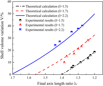
Figure 18. Shell volume variation with internal pressure and axis length ratios. Reprinted from [47], Copyright 2016, with permission from Elsevier.
Download figure:
Standard image High-resolution image3.4. Typical application of dieless hydroforming
Dieless hydroforming has been used to manufacture water tanks, liquid petroleum gas tanks, large building decorative objects, pressure vessel heads and large-size elbow joints with single or double layers. Among them, the maximum diameters of spherical and ellipsoidal shells were 8.6 m and 6 m, as shown in figure 19, respectively. The maximum thickness was 24 mm and the applied materials included low carbon steel, low alloy steel, stainless steel, aluminum alloy, etc [7, 48].

Figure 19. Typical ultra-large shells formed by dieless hydroforming: (a) spherical tank with diameter of 8.6 m, and (b) ellipsoidal spherical tower with long axis diameter of 6 m.
Download figure:
Standard image High-resolution image3.5. Existing problems and further development of dieless hydroforming
The existing major problem in dieless hydroforming is bigger deviation of curvature radius because of no restriction of die. The forming method based on liquid volume loading will be developed to control the curvature radius of the final shell. The dimensional accuracy could be realized by accurately controlling the volume of injected liquid. In addition, the forming at elevated temperature might be explored to solve the rapture while dieless hydroforming of aluminum alloy shells.
4. Integral forming of ultra-large rings
4.1. Radial-axial ring rolling (RARR)
RARR is an advanced incremental forming technology for manufacturing various seamless rings, especially for large-scale, high performance ring [49]. Compared with traditional radial ring rolling, a pair of axial rolls are added in the RARR, as shown in figure 20. The thickness and height of a ring is reduced by the radial stress of the main roll and mandrel, and the axial stress of the upper and lower conical rolls, respectively. The diameter size of the ring is enlarged while the thickness and height of the ring are reduced.
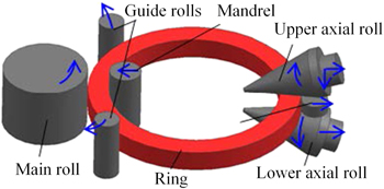
Figure 20. Principle of the radial-axial ring rolling. Reproduced with permission from [50].
Download figure:
Standard image High-resolution imageRARR is an extremely complex, dynamic rolling process with high flexibility. The material flow speed along the radial, axial, and circular directions are different, especially for rolling of large-size rings. The ring with a large size and complex cross-section shape is difficult to form simultaneously. To make the rolling process stable and form a ring with good dimensional accuracy and high performance, the movement of the rolls should be strictly controlled. This includes the rotation motion of the main roll, the radial feed motion of the mandrel, the axial feed, the radial backward and rotation motions of conical rolls, and the centering motion of the guide rolls. Otherwise, severe inhomogeneous deformation will occur in the ring, resulting in defects such as ring climbing, tilting, and sectional depression, as shown in figure 21. A comprehensive theoretical analysis of RARR has been established to guide the rolling movement and deformation [52]. The fundamentals of geometry, kinematics and dynamics in RARR were revealed, in which the interaction between the pressure roll and conical roll motions as well as the temperature variation of the rolled material, were considered [53].

Figure 21. Defects in the radial-axial ring rolling process: (a) distorted shape and (b) sectional depression. Reprinted from [51], Copyright 2013, with permission from Elsevier.
Download figure:
Standard image High-resolution imageThe 3D elastic–plastic and coupled thermomechanical finite element (FE) model was developed to analyze the deformation behavior and roll size effect in the radial-axial ring rolling process [54]. The methods to calculate rolling force, torque, and power were established. Accordingly, the critical conditions of biting into the rolling cavity and stabilizing the ring stiffness stabilizing have been proposed [55]. To ensure enough plastic deformation, the penetrating condition in radial and axial deformation areas should be met [56].
During the rolling process, the rolling temperature, deformation resistance, feeding speed, inertia moment, microstructure, etc, change significantly, especially for the rolling of ultra-large rings. For example, the inner diameter of the ring and the inertia moment change up to 30 times and 150 times, respectively, during the rolling process of a ring with an outer diameter of 10 m. The corresponding rolling process is extremely complex and difficult to control. As the feed speed of the upper axial roll increases, the strain distribution of the rolled ring becomes less uniform while the temperature distribution of the rolled ring becomes more homogeneous. Meanwhile, the radial rolling force and radial rolling moment decreases, whereas the axial rolling force and axial rolling moment increases [57]. The moving coordinate of the centering rolls was calculated by the growing speed of the outer radius of the ring and the angle between the links of the ring's center with the mandrel's center and with the centering roll's center [58]. A theoretical basis and reliable control method of the guide roll based on the ring stiffness condition have been proposed [59, 60]. Based on the rolling deformation condition and technological requirements, the advanced measurement technique and closed-loop control system were used to reasonably match and control motion parameters of the rolls, which could ensure the realization of automatic rolling [61].
By reasonably designing the shape and size of the billets, coordinating and matching the deformation degree and speed in the radial and axial directions, precisely controlling the rolling process parameters, etc, a ring with a large diameter and complex profile could be formed simultaneously. The challenge to obtaining the expected microstructure and mechanical properties still existed due to the non-uniform local deformation and non-uniform temperature distribution, especially for the rolling of ultra-large rings. The coupling of temperature, deformation and multi-loading have great effects on final microstructure and performance. The internal state variable material model was developed, which enables the unified prediction of flow behavior and microstructure evolution during dynamic and post dynamic regime [62], as shown in figure 22. The influence of the ring growth rate on damage development has been investigated [63]. The evolutions of microstructure and texture have also been measured [64]. An improved process for grain refinement of large aluminum alloy rings and its influence on mechanical properties has been developed [65]. The microstructure and performance could be controlled effectively.

Figure 22. Prediction of the deformation and microstructure in the radial-axial rolling process. Reprinted from [62], Copyright 2017, with permission from Elsevier.
Download figure:
Standard image High-resolution imageUp to now, the RARR has been widely used in the manufacturing of bearing rings, flange rings, gear rings, gas turbine rings and rocket capsule rings, etc. The ring shapes have become more and more complex, and the size is extremely large. The world's largest rolled steel ring with up to 16 m in diameter and 126t in weight was manufactured for application in the wind power industry, as shown in figure 23. The corresponding ring rolling mill has an overall height of 22 m, whose radical roll force was 25 MN, and whose axial roll force was 12.5 MN.
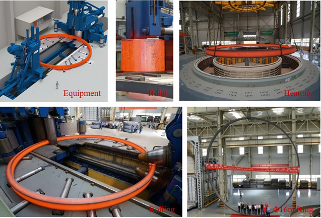
Figure 23. Rolling process of the 16 m diameter steel. Reproduced with permission from [66].
Download figure:
Standard image High-resolution imageThe ring material has ranged from steel to lightweight alloys, such as titanium and aluminum. To meet the needs of aerospace equipment, an ultra-large, 10 m in diameter, aluminum alloy ring was rolled with good dimensional accuracy and high performance, as shown in figure 24.
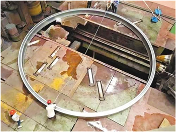
Figure 24. A 10 m diameter aluminum alloy ring. Reproduced with permission from [67].
Download figure:
Standard image High-resolution image4.2. In situ manufacturing process of ultra-large flange
The traditional manufacturing process of a large flange usually includes turning with a large capacity vertical lathe as the final procedure, and the machining costs are very high. Meanwhile, a large-size flange is difficult to transport while the diameter of the flange is greater than 5 m. To solve this problem, the in situ manufacturing process has been developed. The process is an advanced machining technology based on actual field, which can be utilized to manufacture ultra-large flanges with low cost and high precision [68].
A brief description of the manufacturing process follows: (1) the square billets are obtained by forging or cutting a thick steel plate; (2) the complicated cross-sections are then machined on the plane machine; (3) the machined billets are precision bent by a hydraulic press; (4) the curved billet sections are subsequently transported to the construction site, where they are assembled, welded, and then machined into the overall flange by a special small capacity machining tool, as shown in figure 25. In this process, the key technologies are accurate measurement and large-scale motion of a small machine tool. Its main advantages are as follows: the large vertical lathe is replaced by the in situ multifunction machining tool, so that the machining size will not be limited; the cost is very low compared to the traditional method; the precision is high due to the in situ fine machining and lack of welding deformation.
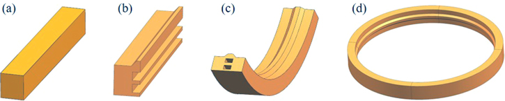
Figure 25. In situ manufacturing process of ultra-large flange: (a) forging or cutting of square billet, (b) section machining by plane machine, (c) precision bending, and (d) in situ assembling, welding and final machining.
Download figure:
Standard image High-resolution imageFigure 26 shows the in situ manufacturing process of a 8.5 m diameter, low alloy steel flang, which has been used in a large wind tunnel [69]. Six pieces of billets were bent after their cross sections were machined on a plane machine, then in situ assembled and welded into a ring, finally machined by a special small capacity lathe with multiple functions, including milling, grinding and polishing. After in situ machining, the roundness of the flange was less than 1/1000, the overall flatness error was within 0.9 mm, and the surface roughness was less than 0.8, which met the high requirements for dimensional accuracy. A 12 m diameter flange was also manufactured by this in situ manufacturing process.
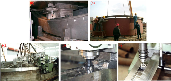
Figure 26. In situ manufacturing process of a low alloy steel flange with 8.5 m in diameter: (a) bending, (b) assembling and welding, (c) multifunction machining tool, (d) milling, and (e) grinding. Reprinted from [68], Copyright 2005, with permission from Elsevier.
Download figure:
Standard image High-resolution image4.3. Existing problems and further development of ring rolling
The low utilization rate of material is the major problem in integral ring rolling process, e.g. the material utilization rate for 5 m diameter integrated ring is less than 10%, which results in very high cost. How to improve the material utilization rate is the main developing trend. Meanwhile, the transportation is very difficult when the diameter exceeds 10 m. It is very urgent to develop in situ, low cost and small scale manufacturing processes and equipment.
5. Isothermal forging of large-size titanium alloy components
5.1. Integral isothermal forging
Isothermal forging is a near-net forming process, in which the dies and the billets are heated to an equal temperature so that the billets can easily flow and fill the complex shapes by a controlled strain rate. Because the forging process is always conducted at high temperature, there are a series of advantages. The deformation resistance is reduced and the workability is increased significantly. The corresponding equipment tonnage is decreased. Meanwhile, the microstructure and performance can be precisely controlled, accompanied by relatively simple processing conditions. Therefore, isothermal forging has been developed as an important near-net forming method for forging large-size, high-performance and complex-shaped titanium alloy components [70].
Since the technology was proposed in the 1960s, many research projects have been conducted on the processing parameters of titanium alloy isothermal forging, the optimization designing of pre-billets and the controlling of microstructure and performance [71–74]. The near-net forging technology has been used in manufacturing aircraft girders, landing gear, frame, turbine blades, etc. One of the most important applications was the titanium alloy integral frame, 3.8 m in width and 1.7 m in height. The corresponding projection area was higher than 5 m2, as shown in figure 27. It was the largest size titanium alloy forging components ever produced, which was used in the F-22 fighter aircraft.
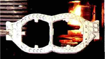
Figure 27. An integral titanium alloy frame with a 3.8 m width and 1.7 m height. Reproduced with permission from [75].
Download figure:
Standard image High-resolution image5.2. Local isothermal forging
How to form ultra-large complex titanium alloy components with small tonnage equipment is a big challenge, which is the effective way to reduce the forming force and control metal flowing in the isothermal forging process of large-size titanium alloy components. Isothermal forging by local loading has been developed to reduce the forming force, control the flow of materials, enhance filling ability and enlarge component size [76], as shown in figure 28.
Figure 28. Schematic diagram of local isothermal forging process and its stress distribution.
Download figure:
Standard image High-resolution imageIn this process, the load is applied to the local zone of the billet and the component is formed by changing the loading zone and controlling the uneven deformation, which provides a feasible way to form large-size complex titanium alloy components using a hydraulic press with small tonnage. An integral titanium alloy component with a projection area of 2 m2 was formed by local isothermal loading on a hydraulic press with 60 MN in tonnage, as shown in figure 29. If integral isothermal forging was used to form this component, a hydraulic press with 200 MN in tonnage was needed.
Figure 29. An integral titanium alloy rib-web component with projection area of 2 m2 formed by a local isothermal forging process.
Download figure:
Standard image High-resolution imageHow to control the uneven deformation and microstructure under the role of multi-fields and multi-factors should be revealed for actual applications. The effects of local loading conditions, including temperature, deformation degree, loading pass, heats, cooling modes, and heat treatment, have been clarified on the microstructure and mechanical properties of TA15 titanium alloy components [77–79]. The deformation behavior and uneven deformation mechanism in the local isothermal forging of a rib-web component were revealed through a combination of theoretical analysis, numerical simulation and experiments [80]. The crystal plasticity models have also been proposed for simultaneously responding to dynamic recrystallization and thermomechanical behavior [81], relating anisotropic deformation behavior to microstructural features [82]. The macro–micro FE modeling of local load forming of large-size complex titanium alloy components has been developed for the deformation behavior and microstructure predictions [83, 84], as shown in figure 30.
Figure 30. Predictions of field variations in local isothermal forging process: (a) temperature; (b) strain; (c) volume fraction of primary alpha phase and (d) grain size. Reprinted from [84], Copyright 2014, with permission from Elsevier.
Download figure:
Standard image High-resolution image
5.3. Existing problems and further development of local isothermal forging
The major problem existing in the local isothermal forging is how to control microstructure and performance in transition and overlap zones after multistep loading, especially under multiple heating conditions. Another problem is how to control the metal flowing between different deformation zones to avoid the underfilling and folding defects, especially for the components with double-sided ribs.
6. Concluding remarks
Integrated structures have been used to replace traditional multipiece welded structures as an effective way of improving reliability and lifetime and reducing weight in the aerospace, aviation, high-speed train, and automobile industries. The applications of integrated structures result in the components becoming ultra-large in size and complex in shape, significantly increasing deformation resistance. The forming equipment and tools for manufacturing large-size integrated structures require an extremely large worktable area and accommodation for very large tonnage, creating a huge challenge for precision forming. Potential directions for developing new forming technologies or improving existing technologies are as followings.
- (1)As for bulk forming, the local loading or reduction of flow stress can be utilized to reduce the forming force. For example, the forming force can be reduced by reducing the action area through local loading or by decreasing the flow stress of deformed materials through some special means, such as thermohydrogen processing. Forming ultra-large components in equipment with a relatively small tonnage but large worktable is becoming a trend, eventually solving a series of problems currently being caused by huge tonnage equipment.
- (2)As for sheet and tube forming, changing the stress state improves the forming limit. For example, the sheet is always deformed under a tensile-compressive stress state by using flexible force-transmitting medias, such as liquid mediums or electromagnetic force, which can be used to avoid the wrinkling and rapture simultaneously, especially for forming the ultra-large size and super-thin curved components.
- (3)In situ manufacturing technology should be developed to reduce cost. The limits in transportation of ultra-large size components make it very difficult to transport them to a site after being machined in another factory. In situ and low-cost manufacturing technologies need to be urgently developed.
- (4)Simulation accuracy should be improved to reduce the experimental cost and time period required. It is very expensive and time consuming to carry out experimental research on full-scale, ultra-large size components. Therefore, high accuracy simulation will play an important role in developing new forming technologies for ultra-large size components.
Acknowledgments
This work was funded in part by the National Key Research and Development Program of China (2017YFB0306304), and the National Natural Science Foundation of China (51705102, U1637209). The authors wish to express their gratitude for the funding.