
Abstract
Diamond tools play a critical role in ultra-precision machining due to their excellent physical and mechanical material properties, such as that cutting edge can be sharpened to nanoscale accuracy. However, abrasive chemical reactions between diamond and non-diamond-machinable metal elements, including Fe, Cr, Ti, Ni, etc, can cause excessive tool wear in diamond cutting of such metals and most of their alloys. This paper reviews the latest achievements in the chemical wear and wear suppression methods for diamond tools in cutting of ferrous metals. The focus will be on the wear mechanism of diamond tools, and the typical wear reduction methods for diamond cutting of ferrous metals, including ultrasonic vibration cutting, cryogenic cutting, surface nitridation and plasma assisted cutting, etc. Relevant commercially available devices are introduced as well. Furthermore, future research trends in diamond tool wear suppression are discussed and examined.
Export citation and abstract BibTeX RIS

Original content from this work may be used under the terms of the Creative Commons Attribution 3.0 licence. Any further distribution of this work must maintain attribution to the author(s) and the title of the work, journal citation and DOI.
1. Introduction
Diamonds have the advantages of high hardness, high wear resistance, low friction coefficient, high modulus of elasticity, high thermal conductivity, low coefficient of thermal expansion, etc. Additionally, diamonds can be sharpened with sharp edges and smooth surfaces for ultra-thin chip generation [1–3]. Diamonds are also considered as an integral tool material in ultra-precision machining [4]. Therefore, the diamond tools are commonly used in the ultra-precision cutting of easy-to cut materials, such as non-ferrous metals [5], electroless nickel [6], optical crystals [7] and optical plastics [8]. Surfaces machined by diamond tools can achieve a roughness of Ra less than 2 nm [9].
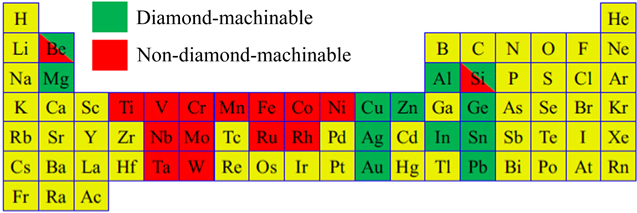
Generally, metals can be categorized into diamond-machinable and non-diamond-machinable, as shown in figure 1 [10, 11]. Diamond tools cannot be directly applied to cut the non-diamond-machinable metals, such as Fe, Cr, Ti, Ni, etc. In diamond cutting processes, the tool undergoes a series of chemical reactions, such as graphitization or oxidation reaction with the above-mentioned elements, resulting in excessive tool wear [12, 13]. For example, with a single crystal diamond (SCD) tool, the maximum cutting edge was worn out by 3.5 μm when cutting stainless steel at a cutting distance of 70 m [14]. With the same cutting conditions, the wear rate of diamond tools reduced one-thousand-fold when cutting non-ferrous metals such as copper and aluminium [15, 16].
Download figure:
Standard image High-resolution imageAs the world's most important metal alloy, steel is considered as non-diamond-machinable, because it is an alloy of iron and carbon. Hence, since diamond turning was introduced in 1940s, researchers have started evaluating and enhancing its capability for cutting of steel. One of the earliest studies can be dated back to 1944 [17], when Merchant has been using diamond tool to cut low carbon steel. Then, Wilks et al [18] and Casstevens [19] tried to create different atmospheric conditions for diamond turning of steel, but its tool life has not been improved so much. It is worth highlighting that diamond cutting of steel material, which is a material widely used for mechanical elements due to the required wear resistance, is a challenging task due to severe thermochemical tool wear. High temperature at the contact spots in cutting regime can lead to reactions between carbon and iron. The following reactions tend to occur [12]:


So, in 1991, researchers started testing other technical methods, such as lowering the temperature to a cryogenic level [20], or making the tool to vibrate with an ultrasonic frequency [21]. As ultrasonic vibration has been found effective in increasing the tool life without introducing large temperature gradient, researchers then upgraded the 1D vibration to 2D vibration to further improve the machining performance [22]. Tool modification [23] and workpiece modification [24] have also been investigated. Brinksmeier et al found surface nitriding could greatly reduce the tool wear in diamond turning of steel. More recently, Zhang et al [25] introduced oxygen-shielded ultrasonic vibration cutting to significantly improve the diamond tool life in cutting of stainless steel and several other non-diamond-machinable metals.
In order to reduce the rapid tool wear caused by tribochemical reactions between diamond tools and workpiece materials containing Fe, researchers have been building an understanding of the wear mechanism of diamond tools, as well as exploring wear reduction processes. In exploring the mechanism of chemical wear, a multitude of experiments and simulation studies [26–28] were conducted. It is generally accepted that in a high temperature and high pressure cutting environment, diamond is converted into graphite under the catalysis of the workpiece materials. Chemical reactions, such as oxidation and atomic exchange of materials, lead to a decrease in the hardness and strength of diamond tools. Rapid tool wear is exacerbated by the microchipping of the cutting edge and the crater of rake face and flank face. However, since the chemical wear of diamond tools is instantaneous, it cannot be observed through traditional experimental investigations. Moreover, the current simulation process cannot fully replicate actual cutting conditions. Thus, further research and understanding of the wear mechanism needs to be established.
Existing research outcomes indicate that, in order to reduce the rapid wear caused by the chemical reaction of diamond tools with ferrous materials, activity between the tool-workpiece materials needs to be reduced, which includes improving the thermal environment of the cutting zone, as well as avoiding direct contact between the tool and the workpiece material [23]. Specific process methods on reducing cutting temperature, reducing contact time, pre-treatment of material surface, etc [10, 11] were then proposed. The processing technologies for reducing chemical activity between the tool and the workpiece materials include: gas protection cutting [19], cold plasma assisted cutting [29, 30], carbon particle protection cutting [31], liquid nitrogen cooling cutting [20], ultrasonic vibration assisted cutting [21], and highly intermittent cutting [32]. Processes that avoid direct contact between the tool and the substrate include: diamond surface coating [23], surface nitriding/phosphorus in workpiece material [24, 33, 34], as shown in table 1. In addition, researchers also introduced multi-physics energy fields, such as magnetic fields and electric fields in cutting processing [35]. The aim is to reduce wear by curtailing chemical activity between the tool and the workpiece material. The above method is paramount to reducing the rapid chemical wear of diamond tools and thereby expanding the actual application of diamond tools to difficult-to-cut materials. However, the above methods also possess some limitations in fundamentally solving the engineering application roadblocks to cutting ferrous metals with diamond tools.
Table 1. Processing technology for reducing chemical wear of diamond tools.
| Theoretical approach | Processing technology |
|---|---|
| Reduce chemical affinity of workpieces and materials | Gas protection cutting |
| Cold plasma assisted cutting | |
| Carbon ion protection cutting | |
| Ultrasonic vibration cutting | |
| Cryogenic cutting | |
| Highly intermittent cutting | |
| Avoid direct contact between the tool-matrix material | Diamond surface coating |
| Surface nitridation |
This paper summarizes the latest research on the chemical wear mechanism of diamond tools. Four typical processing techniques are introduced in detail: ultrasonic vibration cutting, cryogenic cutting, surface nitridation and plasma assisted cutting. The process principles, development status, advantages and disadvantages of the processes are introduced in detail. The goal of the comprehensive introduction of these four processing techniques is to promote industrial application of diamond tools in cutting difficult-to-cut materials. Furthermore, our review aims to serve as a reference and inspiration for future diamond tool manufacturing.
2. Chemical wear mechanism of diamond tools
The forms of diamond tool wear can be divided into mechanical wear and chemical wear [16]. Due to the high hardness of diamond tools, mechanical wear is only a small fraction of total wear. The primary reason why diamond tools are not suitable for cutting metals such as Fe, Cr, Ti, Ni, etc, is that the chemical reaction between the diamond and the workpiece material, which results in severe wear and tear of the tool, including oxidation reaction, graphitization and chipping [13, 34, 36–39], as shown in figures 2–4. Take the graphitization of diamond as an example: Although diamond and graphite are all carbon allotropes, graphite is more stable than diamond [36], from an energy standpoint. Under regular catalysis, there is a tendency to transform to a more stable lamellar graphite structure, as shown in figure 5 [12, 40].

Figure 2. (a) Tool wear after turning Ni at the cutting distance of 20 m and (b) tool wear after turning Ni-P at the cutting distance of 1421 m. Reprinted from [34], Copyright 2010, with permission from CIRP. Published by Elsevier Ltd.
Download figure:
Standard image High-resolution image
Figure 3. SEM images of tool clearance faces after cutting Ni-P alloy. Reprinted from [38], Copyright 2014, with permission from Elsevier.
Download figure:
Standard image High-resolution image
Figure 4. Electron beam induced deposition (EBID) images of tool wear after cutting low carbon steel AISI 1215. Reprinted from [13], Copyright 1980, with permission from Elsevier.
Download figure:
Standard image High-resolution image
Figure 5. Transformation of diamond structure to more stable graphite structure. Reproduced with permission from [40].
Download figure:
Standard image High-resolution imageCurrently, in order to study the wear mechanism caused by graphitization during diamond cutting, researchers worldwide have conducted multiple experiments using finite element simulation and thermal compression studies. These investigations include electronic structure, oxidation reaction, molecular potential energy and molecular diffusion rate, and electron attraction [41–45].
Paul et al [46] analyzed the electronic structures of different metals and concluded that the presence of a large number of unpaired d-electrons in the material causes the covalent bond in the diamond lattice to break, which is the primary reason behind tool wear. In the theory of metal element catalysis, the relationship between metallic catalysts and diamond tool wear was analyzed. Unpaired d-electrons may form intermediate compounds, such as metal-carbon or metal-carbon-oxygen with diamond carbon atoms or non-diamond carbon atoms, which will accelerate the conversion of diamond to graphite, and further aggravate the chemical wear of diamond tools. Experimental results also display that the catalytic effect of metal atoms on diamond graphitization is related to the number of d-orbital holes, as shown in table 2.
Table 2. Electronic structure of elements.
| Element | Price electron structure | Number of d orbital holes | Unpaired d electronic number |
|---|---|---|---|
| Zn | 3d104s2 | — | 0 |
| Mg | 3s2 | — | 0 |
| Al | 3p1 | 0 | 0 |
| Fe | 3d64s2 | 2.2 | 4 |
| Co | 3d74s2 | 1.7 | 3 |
| Ni | 3d84s2 | 0.6 | 2 |
| Cu | 3d104s1 | 0 | 0 |
| Cr | 3d54s1 | — | 5 |
| Ti | 3d24s2 | — | 2 |
Uemura [47] discussed the desorption probability for hydrogen chemisorbed on a diamond surface. It is reported that the essence of metal catalysis is oxidation, and the carbon oxide produced by the phase change of the diamond tool reaction with the CH bond in methane forms a hydrolysis reaction. By measuring the water in the product, the wear rate of the diamond tool can be calculated. As shown in equation (3)

where M, (s), (g) mean metal where M, (s), and (g) mean metal, solid state and gaseous matter, respectively; C(s) stands for carbide; x, y stand for the correlation coefficients.
Narulkar et al [48] combined the actual interaction potential between diamond and iron, and defined the graphitization of diamond crystal by the molecular dynamics (MD) method, as shown in figure 6(a). The experimental results show that at the start of the cutting, the carbon atoms at the diamond cutting edge are transformed from a tetrahedral structure to a close-packed hexagonal graphite structure, as shown in figure 6(b). Then, the carbon atoms in the graphite state diffuse into the workpiece. The wear process caused by graphitization is not performed in units of a single atom, but instead occurs in an intermediate activation state by atomic group, as shown in figures 6(c)–(d). As the current MD simulation did not consider the internal defects, grain size and other characteristics of the material, a noticeable disparity from reality may exist. The simulation results need to be verified by the further experimentations.
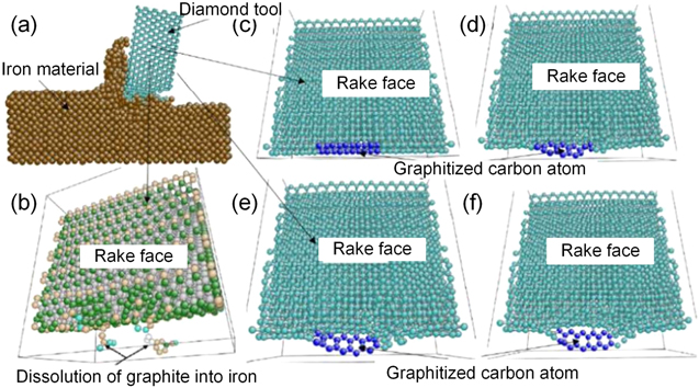
Figure 6. Diamond structure changes to graphite structure during cutting. Reprinted from [48], Copyright 2008, with permission from Elsevier.
Download figure:
Standard image High-resolution imageShimada et al [49] applied MD and corrosion tests to simulate the diamond tool wear process. Results state that the diamond wear mechanism varies at different temperatures. When temperatures reach above 1000 K, tool wear is primarily caused by the exchange of carbon atoms on the diamond surface with iron atoms in the steel alloy. When the temperature dips below 900 K, tool wear is mainly caused by the oxidation reaction precipitated by the oxide in the steel workpiece.
Regarding the atomic magnitude simulation of the catalytic effect of iron atoms on diamond, Guo et al [50, 51] found that the atomic structure alters in the diamond graphitization process in accordance with the vertical alignment principle. It has been discovered that the unpaired electrons in the iron valence electron layer interact with the electrons of the diamond atoms, in order to form a chemical bond that attracts the diamond carbon atoms and shifts the diamond atoms up and down. By changing the position of the carbon atoms, the hexagonal structure of the diamond is gradually reformed into a graphite structure, as shown in figure 7.
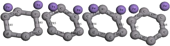
Figure 7. Graphitization change process of diamond hexagonal ring structure with the action of iron atom. Reproduced with permission from [50].
Download figure:
Standard image High-resolution imageConcerning the MD simulation of the diamond cutting iron, Zou et al [52] found that the effective temperature coefficient and thermal vibration kinetic energy of the diamond lattice were increasing due to the high temperature and pressure in the cutting zone, which reduced the reaction activation energy of diamond. This then allows the carbon atoms in the tetrahedral structure at the cutting edge to undergo C–C bond cleavage. Consequently, the carbon/iron atoms tend to form Fe–C bonds, as shown in figure 8. However, these Fe–C bonds have poor thermal stability and are easily broken. Furthermore, the carbon atoms tend to form a more stable C–C hexagonal structure, which is the graphite atomic structure. Figure 9 presents the radial distribution function curves of the diamond tool before and after the simulation, respectively.
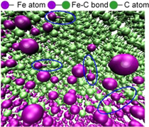
Figure 8. Partial enlarged drawing of iron carbon atom bonding (Fe–C). Reprinted from [52], Copyright 2018, with permission from Elsevier.
Download figure:
Standard image High-resolution image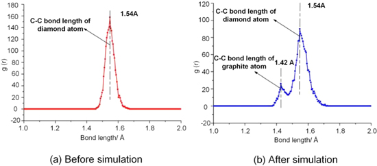
Figure 9. Radial distribution function curves of diamond tool. Reprinted from [52], Copyright 2018, with permission from Elsevier.
Download figure:
Standard image High-resolution imagePertaining to the numerical simulation of diamond-cutting die steel 3Cr2NiMo, Zou et al [28, 52] established a diffusion model in relation to the carbon atoms of diamond tool penetrating chips and machined surfaces. The model revealed that the distribution laws of carbon atom concentration are linked to the diffusion distance, diffusion time, and the original carbon content of the workpiece material. During the practical cutting process, the action of thermal-mechanical coupling in the cutting zone stimulates both the ferrous atoms and the carbon atoms on the surface of the diamond tool. Furthermore, the ferrous metal atoms tend to vibrate up and down at a particular frequency, causing the distance between the two metal atoms to increase. Since the diameter of the carbon atom is much less than the diameter of iron atom, the carbon atoms that disassociated from the diamond diffuse into a ferrous metal lattice. Figure 10 illustrates the diffusion mechanism of carbon atoms in diamond-cutting ferrous metals.
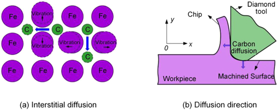
Figure 10. Diffusion mechanism of carbon atoms in diamond-cutting ferrous metals. Reprinted from [52], Copyright 2018, with permission from Elsevier.
Download figure:
Standard image High-resolution imageBai et al [53] studied the diamond graphitization wear behaviour under diverse conditions based on MD simulation. They applied the six-fold ring method to identify the structural characteristics of graphite and diamond, and consequently, discovered that temperature and crystal orientation have a significant impact on the graphitization of diamond. The study concluded that 1000 °C is considered the critical temperature of the graphitization of diamond. Furthermore, it should be noted that although graphitization is more easily achieved with the (111) plane of diamond, the (100) plane of diamond has the highest anti-graphitization property.
The mechanism of chemical wear is investigated at the atomic level, including atomic unpaired d-electrons and d-orbital holes, C–H bond oxidation, atom exchanging, and interatomic potential energy. However, it should be noted that there are limitations in both MD simulation and hot corrosion testing. Multiple studies considering atomic structure, material affinity, ambient temperature, etc have been completed, but the actual cutting process is more complex. Cutting force, grain size, internal defects of materials, cooling state, dynamic mechanical properties of materials, etc, are critical in investigating the mechanism of diamond tool wear. However, the impact of the aforementioned properties has not been thoroughly considered in previous studies.
3. Process method for reducing chemical wear of diamond tools
Although the chemical wear mechanism of the diamond tool has not yet been comprehensively examined, some fundamental consensus has been achieved. The complex thermal-chemical action during cutting along with the high chemical affinity between the workpiece material and the diamond tool are the primary factors precipitating the thermal-chemical wear of the diamond tool.
To achieve the successful application of diamond tools in diamond-cutting Fe, Cr, Ti and Ni, it is necessary to decrease the chemical affinity of the tool-workpiece by reducing the thermal action in the cutting zone or reducing the direct contact between the tool and the workpiece. Thus, this section will introduce four typical machining processes that can help achieve the aforementioned precision machining of difficult-to-cut materials. These four processes are: ultrasonic elliptical vibration cutting, cryogenic cutting, nitriding surface modified cutting, and plasma assisted cutting. A clear understanding of the principle, development status, and advantages and disadvantages of these processes will be established.
3.1. Ultrasonic vibration cutting
In the past few decades, ultrasonic vibration cutting technology has been applied to diamond cutting of difficult-to-cut materials [54–57]. In particular, the elliptical vibration cutting technology proposed by Shamoto in 1994 [58] effectively promoted the utilization of diamond cutting technology in precision cutting iron-based materials. Elliptical vibration cutting elicits a single/double excitation, which causes the tool tip to vibrate in an elliptical trajectory with high frequency and intermittent material removal. This machining process is shown in figure 11 [59]. During each vibration cycle, the tool begins to cut the workpiece material at Position B, and the workpiece material is removed as chips. Position C is the cutting end point. Then the tool is gradually separated from the workpiece material. During the cutting process, the cutting feed rate is less than the maximum vibration speed in order to ensure that the tool is separated from the workpiece material during each vibration cycle. Compared to conventional cutting processes, elliptical vibration cutting is an intermittent cutting method that effectively reduces chip thickness and cutting force. At the same time, the intermittent cutting process allows the tool and workpiece material to be cooled efficiently by the cutting fluid or ambient air in the cutting area, thus reducing the temperature of the cutting zone and inhibiting the adhesion of the workpiece material to the rake face of the cutting tool [60–62]. As a result, the thermo-chemical wear can be effectively suppressed.
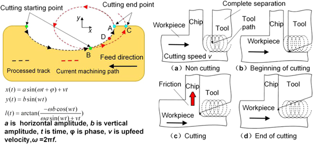
Figure 11. Elliptical vibration cutting principle. Reproduced with permission from [59]. © Korean Society for Precision Engineering 2018.
Download figure:
Standard image High-resolution imageUltra-precision machining of difficult-to-cut materials, such as ferrous metals, can be achieved by applying elliptical vibration diamond cutting technology. Shamoto and Suzuki [14, 59, 63–65] have conducted in-depth studies on the principles, equipment and processes behind the ultrasonic elliptical vibration process. Conducting comparative tests of ordinary cutting and ultrasonic elliptical vibration cutting confirms that elliptical vibration cutting reduces tool wear and improves cutting surface quality, as shown in figure 12 [14]. As mentioned above, applying the traditional ordinary cutting method causes the cutting edge to have a wear amount of 3.5 μm at a cutting distance of 70 m. The surface roughness Rz is 0.52 μm, as shown in figure 12(b). However, employing ultrasonic elliptical vibration cutting allows the surface roughness Rz to remain less than 0.04 μm, even when the cutting distance is 1065 m, as shown in figure 12(f).

Figure 12. Machinability of diamond cutting hardened steel with elliptical vibration cutting and ordinary cutting. Reprinted from [14], Copyright 2014, with permission from Elsevier.
Download figure:
Standard image High-resolution imageZhang et al [25, 66, 67] reported that the ultrasonic elliptical vibration cutting reduces tool wear by increasing the air/oxygen pressure between the tool and workpiece, as well as promoting the formation of an oxide layer on the machined surface. The presence of air pressure and oxide layers help reduce direct contact between the tool and the workpiece, which in turn, reduces the chemical wear of the diamond tool. The reduction of cutting force in ultrasonic elliptical vibration processing is also considered an important aspect in reducing the tool wear.
Zhang et al [68] studied the feasibility of tungsten carbide (with bonding material of Ni and Co) machining with elliptical vibration cutting technology. The study reports that elliptical vibration cutting can significantly reduce the adhesion between the tool and the workpiece material, which is advantageous to reducing the adhesion wear and/or considerable thermo-chemical reaction. This may be why elliptical vibration cutting results in a significant reduction in diamond tool wear, as shown in figure 13.

Figure 13. Tool cutting edge under different cutting conditions. Reprinted from [25], Copyright 2019, with permission from Elsevier.
Download figure:
Standard image High-resolution imageKlocke et al [69, 70] fabricated the steel optical mold by using ultrasonic vibration cutting with diamond tools. The experimental results show that ultrasonic vibration can effectively reduce the wear rate of diamond tools. They reported that the ultrasonic vibration causes discontinuous contact between the diamond tool and the machined surface during cutting. Additionally, chemical reactions and diffusion processes are periodically interrupted. Thus, the cutting temperature does not continue to rise. Moreover, ultrasonic vibration also facilitates the cutting fluid entering the cutting area, in order to ensure the lubrication and cleaning of the tool.
Zou et al [71, 72] revealed the wear mechanism of the diamond tool by ultrasonic elliptical vibration cutting of the die steel 3Cr2NiMo. As shown in figure 14, they compared the diamond tool wear in ultrasonic vibration-assisted turning (UVAT) of die steels with that in conventional turning (CT). Results display that the tool wear on the flank face VB in CT was 18.8 μm at a cutting distance of 100 m, which is much larger than that in UVAT (VB 11.2 μm). Thus, tool life had been markedly improved by UVAT. Furthermore, it should be noted that diamond tool wear is closely related to the feed rate and the cutting speed, but is insensitive to the depth of cut.
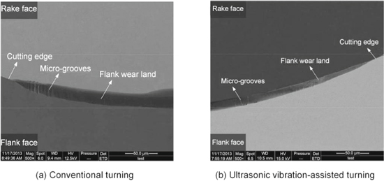
Figure 14. The comparison of the worn surface morphology of diamond tools. [72] 2017, reprinted by permission the publisher (Taylor & Francis Ltd).
Download figure:
Standard image High-resolution imageWang et al [12] experimentally verified that elliptical vibration cutting is advantageous to improving surface quality and suppressing tool wear in diamond cutting of hardened steel. Figure 15(a) shows the severe tool wear, with the machined surface quality deteriorating at a cutting distance of 150 m in ordinary cutting. On the contrary, the cutting edge of the diamond tool have no obvious wear in elliptical vibration cutting, and the machined surface roughness Rz is less than 40 nm, even at an increased cutting distance of 190 m, as shown in figure 15(b).

Figure 15. Comparison between traditional cutting and ultrasonic elliptical vibration machining quality and tool wear. Reprinted from [12], Copyright 2011, with permission from Elsevier.
Download figure:
Standard image High-resolution imageBulla et al [73, 74] examined the influences of different steel alloys on machining results in ultrasonic assisted diamond turning process. Figure 16 illustrates several steel alloys with different chromium (Cr) contents. The Son-X ultrasonic tooling system UTS1, which operates at a frequency of 80 kHz, was installed on a Moore Nanotech 350FG. The vibration amplitude was controlled at 0.8 μm and the cutting speed was set to be 4 m min−1. The cutting edges of diamond tools, surface roughness Ra, and chip formation after machining the alloys, Polmax, Mirrax ESR and 1.2767 ESU, are shown in figure 17, which displays that no obvious tool wear nor severe damage was detected. In contrast, stronger tool wear was observed in the tool that machined the M390. Thus, it can be concluded that in general, ultrasonic vibration assisted cutting suppresses excessive diamond tool wear efficiently.

Figure 16. Several steel alloys for experiments. Reproduced with permission from [73].
Download figure:
Standard image High-resolution image
Figure 17. Representative tool wear, surface qualities and the formed chips after the machining of different alloys. Reproduced with permission from [73].
Download figure:
Standard image High-resolution imageSong et al [75] fabricated the artificial Co–Cr–Mo alloy joints by elliptical vibration cutting. Figure 18 illustrates that the machined mirror surface by elliptical vibration cutting has a surface roughness of less than 25 nm P–V at a cutting speed of 190 mm min−1, which remained virtually unchanged up to a cutting distance of approximately 14 m.
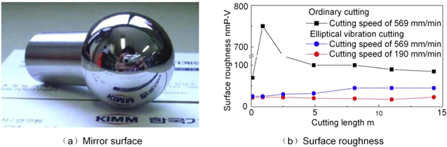
Figure 18. Surface quality and machined surface roughness of elliptical vibration cutting. Reprinted from [75], Copyright 2010, with permission from Elsevier.
Download figure:
Standard image High-resolution imageFigure 19 shows the diamond tool edge at a cutting distance of 14 m by ordinary cutting. Both excessive flank wear and microchipping were observed. However, as shown in figure 20, the diamond tool edge at a cutting distance of 14 m by elliptical vibration cutting did not exhibit apparent abrasive flank wear or microchipping in the tool edges. Furthermore, tool wear did not occur even at a cutting speed of 190 mm min−1.
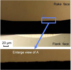
Figure 19. Diamond tool edge after a cut of about 14 m by ordinary cutting. Reprinted from [75], Copyright 2010, with permission from Elsevier.
Download figure:
Standard image High-resolution image
Figure 20. Diamond tool edges with a cutting distance of about 14 m in elliptical vibration cutting with cutting speeds of (a) 569 and (b) 190 mm min−1. Reprinted from [75], Copyright 2010, with permission from Elsevier.
Download figure:
Standard image High-resolution imageNowadays, ultrasonic vibration cutting devices not only exist in laboratories, but also in a series of industrial and commercial products [74–78]. Typical manufacturers, such as TAGA Electric in Japan, and Son-X from Fraunhofer Institute for Production Technology (IPT) in Aachen, German. TAGA Electric has fabricated Sonic Impulse EL-50 series elliptical vibration cutting devices with vibration frequencies over 30 kHz. As shown in figure 21, model EL-50jz has a vibration frequency of 34 ± 1.5 kHz and vibration amplitudes of 4.0 μmp−p.
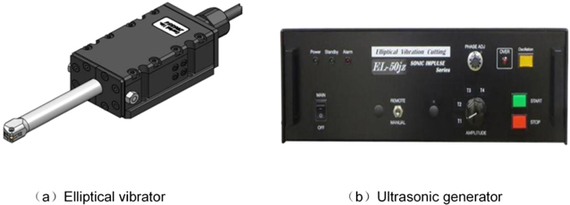
Figure 21. Sonic impulse EL-50jz elliptical vibration cutting system [75].
Download figure:
Standard image High-resolution imageFigures 22(a) and (b) illustrate the ultrasonic tooling systems (UTS1 and UTS2) fabricated by Son-X. The systems' vibration frequencies can reach up to 80 kHz and 100 kHz respectively, with a maximum vibration amplitude of 4.0 μmp-p. The completed surface roughness Ra is approximately 3 nm. There was no apparent diamond tool wear after machining the concave and convex parts.

Figure 22. Son-X ultrasonic tooling system and its finished surface quality. [76–78] © Springer-Verlag London Ltd, 2017. With permission of Springer.
Download figure:
Standard image High-resolution imageMany ultrasonic vibration systems have been developed by scientific research institutes around the world. However, as our technological society continues to advance, more commercial ultrasonic vibration devices will be fabricated to reach the high standards of ultra-precision machining detailed in this section.
Ultrasonic elliptical vibration cutting allows the tool to separate from the workpiece during each vibration cutting cycle. This process is beneficial because it enables the coolant to fully enter the cutting area, thus reducing the cutting temperature while increasing the lubrication. Moreover, it may also reduce the chemical reaction wear caused by direct contact between the tool and the workpiece material. Therefore, while ordinary diamond cutting can only achieve dozens of meters of ferrous metal precision cutting, ultrasonic elliptical vibration diamond cutting of ferrous metals can achieve up to a cutting distance of 3–5 km. However, in terms of tool life, it is only suitable for processing small-scale workpieces. Additionally, it is limited by the complete separation critical speed. The cutting speed is much lower than the maximum vibration speed in the cutting direction. For instance, the average cutting speed is generally 1 m min−1 in elliptical vibration cutting of steel, and machining efficiency is much lower. In order to enhance machining efficiency, vibration amplitude and frequencies need to be increased in future studies.
3.2. Cryogenic cutting
Liquid nitrogen assisted cutting employs liquid nitrogen's extremely low temperatures to form an ultra-low temperature environment in the cutting zone, which diminishes the chemical reaction between the diamond tool and the workpiece. Low temperatures can also alter the physical and chemical properties of the workpiece material as well as improve the material's processability [79, 80].
During liquid nitrogen cooling, liquid nitrogen is sprayed directly into the tool-workpiece contact zone for lubrication cooling, as illustrated in figure 23 [81]. By reducing the cutting temperature, both tool life [82, 83] and machined surface quality [84, 85] can be noticeably improved.
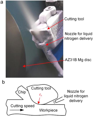
Figure 23. Liquid nitrogen cooling cutting schematic. Reprinted from [81], Copyright 2012, with permission from Elsevier.
Download figure:
Standard image High-resolution imageThe cutting process with liquid nitrogen cooling reduces chemical reaction wear between the tool and the workpiece by generating a low temperature environment. Currently, this technique has been applied to precision cutting of difficult-to-cut metals, such as stainless steel [80, 84–87], titanium alloys [80, 88], and aluminum alloys [89]. Cryogenic cooling is also beneficial to reducing cutting force, improving machined surface quality, decreasing cutting temperatures, and diminishing tool wear.
Brinksmeier et al [23] examined diamond tool wear by turning AISI 1045 steel in modified experiments. As shown in figure 24, they found that even at a cutting distance of 12 m, excessive flank wear, as well as rounding of the cutting edge, occur, in addition to approximately 20 nm of crater wear at low cutting speeds. However, with the application of liquid nitrogen, tool life was enhanced tenfold and the radius of the cutting edge was maintained.

Figure 24. Diamond tool wear with or without liquid nitrogen turning. Reprinted from [23], Copyright 2001, with permission from CIRP. Published by Elsevier Ltd.
Download figure:
Standard image High-resolution imageEvans et al [20] applied liquid nitrogen cryogenic cooling technology to stainless steel (400 series) cutting with diamond tools. The temperature of the cutting zone was below a critical temperature when the diamond was graphitized. A machined surface roughness Ra of less than 25 nm was achieved at a cutting area of 1000 mm2.
Liquid nitrogen cooling is a powerful application in reducing the cutting temperature, which allows for a significant reduction in diamond tool wear. However, there are some challenges that need to be taken into account. For instance, it is difficult for liquid nitrogen to completely enter the cutting area due to the direct contact between the tool cutting edge and the workpiece material in the cutting process. Moreover, the purpose of diamond cutting is typically to obtain high-precision elements, however, it is easy to cause local deformation of the workpiece in low-temperature environments. Thus, it can cause difficulties in achieving high accuracy requirements. Due to the above-mentioned shortcomings, the practical application of liquid nitrogen ultra-low temperature cooling to reducing the chemical wear of diamond tools faces limitations.
3.3. Efficient lubrication cutting
Minimum quantity lubrication (MQL) has attracted widespread attention in the field of manufacturing due to its excellent lubricating effect. Recently, numerous experimental results [90–92] have demonstrated that MQL, which is considered an environmentally friendly machining method, can both effectively reduce tool wear and improve the machined surface quality.
Zou et al [93] combined cryogenic cutting with MQL and proposed the application of cryogenic minimum quantity lubrication (CMQL) cutting, which was considered as a new type of green machining technique. Based on CMQL, a series of turning experiments of 3Cr2NiMo die steel were conducted to investigate the effect of CMQL on the machinability of the diamond tool. Further, the experiment also combined carbon nanofluid and ultrasonic vibration-assisted turning in CMQL to analyze the wear suppression mechanism in the diamond-cutting of ferrous metals. As presented in figure 25, the experimental results show that MQL and CMQL have clear advantages in reducing tool wear. In particular, CMQL can help achieve the longest tool life. Figure 26 presents the cooling and lubrication mechanisms of CMQL.

Figure 25. Comparison of diamond tool wear in different machining methods (CGT—cryogenic gas turning, OT—ordinary turning, MQL—minimum quantity lubrication; CMQL—cryogenic minimum quantity lubrication). [93] 2017, reprinted by permission from the publisher (Taylor & Francis Ltd).
Download figure:
Standard image High-resolution image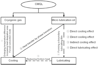
Figure 26. The cooling and lubrication mechanism of CMQL. [93] 2017, reprinted by permission of the publisher (Taylor & Francis Ltd).
Download figure:
Standard image High-resolution imageTo further reduce diamond tool wear in diamond-cutting ferrous metals, researchers have proposed improving the coolant and lubrication used. Inada [31, 94] et al proposed ion-shot coolant with carbon particles to inhibit diamond wear. A chemical film is formed on the surface of the diamond tool to reduce the chemical reaction between the carbon atoms in the diamond and the iron in the workpiece material. High carbon chromium steel (SUJ-2) and pre-hardened mold steel (SUS420J-2) were both applied to gauge the wear progress of the diamond tool. As shown in figure 27, experimental results indicated that a protective film on the diamond tool surface was created. The film prevented direct contact between the tool and the workpiece as well as increased tool life. Furthermore, the ion-shot coolant softened the top surface of the workpiece, which helped enhance material removing. However, there has been no clear explanation regarding the formation mechanism of the softening layer. Additionally, the carbon particle concentration largely depends on the carbon content of the workpiece. Moreover, determining whether the carbon ion-shot coolant can effectively enter the tool-workpiece interface, and whether the softened layer of the workpiece affects the accuracy of the machined part, requires further experimentation and analysis.
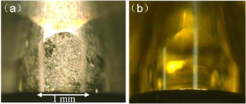
Figure 27. (a) Carbon film on the flank face of the diamond tool after cutting and (b) the original tool. Reprinted from [31], Copyright 2011, with permission from CIRP. Published by Elsevier Ltd.
Download figure:
Standard image High-resolution image3.4. Surface nitridation
The purpose of the nitriding modification process is to avoid direct contact between the diamond tool and the workpiece. The catalytic effect of the workpiece material on diamond tool wear can be significantly reduced. The chemical reactivity between carbon atoms in diamond tools and iron nitrides in workpieces is markedly lower. Therefore, tool wear can be greatly diminished and high surface quality can be obtained. Hence, the nitriding process on the machined surface of ferrous materials has become an essential approach in reducing the wear of diamond tools [84, 85]. The principle step of the nitriding process is that a chemical reaction generates a layer of nitrogen compound on the top surface of the workpiece. The thickness of the modification layer is controlled by heat treatment parameters, including temperature and processing time, as shown in figure 28 [95–97]. During the cutting process, the depth of the cut is precisely controlled guaranteeing that it is less than the thickness of the compound layer.
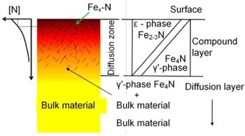
Figure 28. Cross section of the material phase distribution with surface nitridation. Reprinted from [95], Copyright 2011, with permission from Elsevier.
Download figure:
Standard image High-resolution imageBrinksmeier et al [24, 98, 99] experimentally verified the effectiveness of surface nitridation on reducing diamond tool wear. In the cutting experiments, the workpieces (42CrMo4, C45, X170CrVMo18-3-1) were nitrided to form iron nitride on their top surfaces, preventing the direct contact between the iron atom and the diamond tool in the cutting area. The research results concluded that the flank wear VB was 36 μm at a cutting distance of 500 m when cutting the untreated steel surface with the diamond tool. In contrast, the tool wear was markedly reduced at the same cutting distance when cutting the nitriding steel, as shown in figure 29.
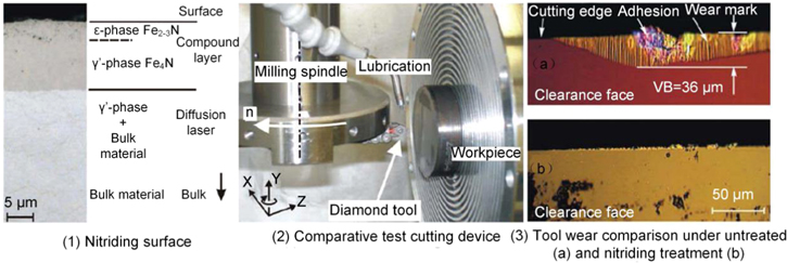
Figure 29. Effect of untreated and nitrided surface on wear performance of diamond tool. Reprinted from [24], Copyright 2006, with permission from CIRP. Published by Elsevier Ltd.
Download figure:
Standard image High-resolution imageFang et al [100] conducted a series of experiments on diamond cutting of nitriding stainless steel. The results demonstrated that the nitride layer (Fe2-3N) generated on the machined surface of the workpiece can prevent the diamond tool from direct contact with the substrate material. Experimental results in figure 30 [100] also revealed that nitriding pure steel has excellent machinability. The surface roughness of the nitriding pure steel sample is less than 6 nm and additionally, where the tool wear was significantly reduced. Because Fe2-3N exhibits high brittleness and hardness, tool wear is primarily caused by the micro-chipping.
Figure 30. Surface quality of nitrided surface and wear of diamond tool. Reproduced with permission from [100].
Download figure:
Standard image High-resolution imageLi et al [101] reported that iron nitride powder metallurgy steel is a potentially favourable material for mirror surface finishing via diamond tools, since it can reduce machined surface roughness to be less than 10 nm. Experiments conducted show that without the nitriding process, the flank face wear VB is 16 μm in the diamond cutting of die steel. With identical cutting conditions, the VB is 1.16 μm when cutting with the nitride powder metallurgy steel, as shown in figure 31.

Figure 31. Wear of diamond tool after machining powder sintered iron nitride. Reproduced with permission from [101].
Download figure:
Standard image High-resolution imageIt should be noted that the tool modification process is also a feasible technique to reduce the chemical reactivity between the diamond tool and the workpiece. Similar with the nitriding modification process on workpiece materials, the ion implantation as a diamond tool modification process was recently adopt to micromachining of ferrous metal [102]. Significant improvements in the wear resistance of an irradiated diamond tool are verified due to the increased stability against exfoliation and the potentially lower heat generation at the tool-chip interface for the graphitization process.
Compared to other machining processes, the nitriding process reduces the chemical affinity between the diamond tool and the workpiece material by altering the material's properties. However, it should be noted that the nitriding process also include a few disadvantageous, such as uneven nitriding layer, increased hardness of the workpiece, a residual nitriding layer on the finished surface, etc. Specifically, the nitriding modification of the workpiece material leads to increased hardness and brittleness, which frequently causes the chipping of diamond tool.
3.5. Plasma assisted cutting process
The primary cause of chemical wear in diamond tools is that atoms such as Fe and Ti contain a vast quantity of unpaired d-electrons, which will destroy the covalent lattice of diamonds, resulting in rapid tool wear. The principle behind plasma-assisted cutting is modifying the workpiece material and forming a substance with low chemical affinity to diamonds, thus achieving the reduction of chemical wear in diamond tools.
The plasma is a gas, which is commonly nitrogen or air compressed by high pressure ionization. The outer electrons of the gas molecules absorb enough energy to break away from the nucleus. The gas then becomes a neutral non-equilibrium composed of active particles, such as charged ions and free electrons. The material is sprayed directly into the cutting zone so that chemical affinity between the tool-workpiece interface is reduced. Furthermore, the plasma acts as a lubricant, thus reducing the built-up edge and decreasing the thermal generation in the cutting zone, as shown in figure 32 [29, 40, 103, 104].

Figure 32. Principle of plasma generation and schematic diagram of auxiliary cutting application. (Top left) Reproduced with permission from [29]. (Top right) Reproduced with permission from [40]. (Bottom left) Reproduced with permission from [103]. (Bottom right) Reprinted from [104], Copyright 2018, with permission from Elsevier.
Download figure:
Standard image High-resolution imageEquations (4)–(6) below use Fe as an example to introduce the mechanism of plasma assisted cutting process [104].


N is derived from N2, NO, and N + 2 in the plasma. O is derived from NO and O2 in the plasma. N and O may also be from a small amount of air; a, b, c stand for the correlation coefficients; x, y, z represents the number of atoms in the compound.
The reaction displayed in equation (2) is the dominant reaction between the plasma and the cutting interface. It is speculated that FexCyNz is primarily generated by the active particles in the plasma and the C atoms after the graphitization of the diamond tool has occurred. The FexCyNz is then adsorbed into the workpiece surface. During the cutting process, the complex thermal actions between the tool-workpiece contact interface also induce the reactive ions to generate new compounds, such as Fe(CO)2(NO)2 and Fe(2/3/4)N, as shown in equations (3) and (4) [105].
The plasma assisted cutting process was first proposed by Blomgren in 1972 [30]. The gas is first ionized by using a high-voltage DC power source, followed by cooling the workpiece and the cutting tool with a dual nozzle. Subsequent studies have demonstrated the characteristics of plasma. The physical and chemical properties of the workpiece material are transformed by increasing the wettability of the workpiece, which is advantageous to lengthening tool life [106], reducing cutting temperature [107, 108], and enhancing surface quality [109]. Therefore, plasma assisted cutting is another practical and beneficial method that can be applied to the diamond cutting process.
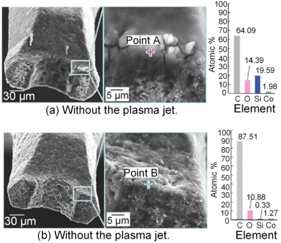
Katahira et al [110] applied a cold plasma to lubricate and cool the cutting tool in the micro-milling of SiC using polycrystalline diamond tools. Experimental results demonstrate that cold plasma can improve the hydrophilicity of the cutting tool as well as reduce the adhesion of the workpiece material to the cutting tool. Thus, the machined surface roughness can be achieved into 0.73 nm with the application of cold plasma. Even at a cutting distance of 3000 mm, the surface roughness can still be maintained at 1–2 nm. Moreover, the energy dispersive spectrometer (EDS) investigations have shown that plasma can significantly reduce the adhesion of the SiC workpiece material to the cutting tool. It is effective in reducing both friction and wear in the cutting tool, as shown in figure 33.

Figure 33. PCD tool after repeated machining over a cutting distance of 3000 mm. Reprinted from [110], Copyright 2015, with permission from CIRP. Published by Elsevier Ltd.
Download figure:
Standard image High-resolution imageXu et al [111] conducted friction tests and thermal analyzes in the experimental investigations of plasma assisted machining steel NAK80 by diamond tool. The mechanism of nitrogen cold plasma in reducing diamond graphitization wear was examined. It was reported that the sliding friction between the diamond and steel can be effectively reduced in the nitrogen-cooled plasma atmosphere. Hence, heat generation between the diamond tool and the workpiece can be significantly reduced as well in the cutting area, as illustrated in figure 34. Moreover, in the nitrogen cold plasma treatment, the graphitization temperature in the friction pair increased from 885 °C to 1185 °C, which is extremely advantageous to the reduction of graphitized wear in the diamond tool.
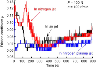
Figure 34. Friction coefficient curves in different atmospheres. Reprinted from [110], Copyright 2015, with permission from CIRP. Published by Elsevier Ltd.
Download figure:
Standard image High-resolution imageHuang et al [93, 112, 113] administered a series of experimental and MD simulation exercises to explore the mechanism of plasma assisted cutting in diamond machining steels. They have found that iron atoms reduce the graphitization temperature of diamond, while ferrous metals treated by nitrogen cold plasma increase graphitization temperature during diamond cutting. A multitude of active particles react with the ferrous metal to generate a nitride with a lower chemical affinity to diamond. The nitrogen-cooled plasma can significantly reduce the oxidative wear and adhesive wear of the cutting tool. Combined with ultrasonic elliptical vibration cutting, the plasma can enter the cutting area much more easily, and thus, a better processing quality can be obtained. Figure 35 shows the cold plasma-elliptical vibration cutting experimental device and the tool wear with different cutting conditions [104, 114]. The combination of the plasma and ultrasonic elliptical vibration cutting is exceptionally effective in reducing diamond tool wear.
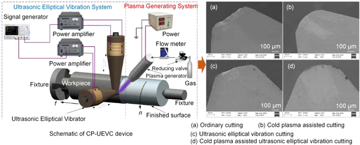
Figure 35. CP-UEVC experimental device and tool wear under different cutting conditions. (Left) Reprinted from [104], Copyright 2018, with permission from Elsevier. (Right) [114] © Springer-Verlag London 2015. With permission of Springer.
Download figure:
Standard image High-resolution imageCold plasma assisted cutting has achieved ground breaking advancements in recent years. It is an important piece of technology in reducing the chemical wear of diamond tools, due to its ability to generate a material with low chemical affinity to diamond. However, there still exist a few challenges in the plasma mechanism and its process:
- 1.The effect of each active component on reducing the chemical affinity between the diamond tool and the ferrous metal is unclear.
- 2.The length of the cold plasma jet is limited to millimetre dimensions, which makes it difficult for the active particles in the cold plasma jet to be efficiently transported into the tool-workpiece contact interface.
- 3.During the transport of cold plasma, the interaction between gas molecules and particles in the air with the active particles in the cold plasma will aggravate plasma quenching, resulting in a greatly-reduced concentration of active particles reaching the tool-workpiece contact zone.
4. Summary and outlook
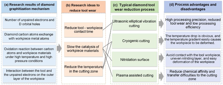
Metal materials such as Fe, Cr, Ti, and Ni, represented by ferrous metals, cannot be directly machined by diamond tools. During the cutting process, the diamond tool will undergo excessive chemical wear due to catalysis with the workpiece material. In order to combat this critical challenge, many researchers have been investigating the mechanism of diamond tool wear and the wear reduction process. Recently, it has been concluded that the chemical wear of the diamond tool is primarily caused by metal catalysis in high-temperature and high-pressure coupling conditions. Researchers have explained the four main mechanisms behind diamond tool wear, as detailed below and summarized in figure 36(a).
- 1.The number of unpaired d-electrons and d-orbital holes around the atom of the workpiece material, such as Fe, Cr, Ti and Ni. This causes the covalent bond in the diamond lattice to break, and can potentially precipitate the formation of metal-carbon or metal-carbon-oxygen intermediate complexes, hence catalyzing the chemical reaction between the diamond and the workpiece material.
- 2.Exchange and diffusion of carbon atoms. The carbon atoms in the diamond switch with the metal atoms in the workpiece, causing the graphite carbon atoms on the diamond surface to diffuse into the workpiece material. This also engenders the graphitization of the diamond. The graphitized carbon atoms will diffuse into the metal workpiece in the form of atomic groups.
- 3.Oxidation reaction between carbon atoms and metal atoms under high-temperature and high-pressure environments. in a high temperature and pressure environment, the carbon atoms will react with the oxides in the metal materials, and thereby cause rapid wear in the diamond tool.
- 4.The interaction between the diamond tool and the unpaired electrons on the outer layer of the workpiece material. The outer electrons of the metal atom will interact with the electrons in the diamond, thus forming a chemical bond. The chemical bond will prompt the diamond carbon atom to move, resulting in graphitization of the diamond.
Figure 36. Graphite wear mechanism of diamond tools and typical anti-wear process.
Download figure:
Standard image High-resolution image
The above-mentioned conclusions explain the principles behind the rapid chemical wear of diamond tools, and are invaluable to the study of diamond tool wear and wear resistance.
The diamond wear reduction process starts with three main aspects: reducing cutting temperature, contact time, and the affinity between the tool and the workpiece, as outlined in figure 36(b). Achieving all three will reduce the diffusion ratio of diamond carbon atoms, and moreover, reduce the catalytic effect of metal atoms on diamond tool wear. Four typical methods for reducing diamond tool wear were introduced, as encapsulated in figure 36(c). Each processing technology detailed in this paper possess its own advantages in reducing the graphitization wear of the diamond tool, but none are without shortcomings, as summarized in figure 36(d).
Ultrasonic elliptical vibration cutting can reduce machined surface roughness to the nanoscale. Additionally, the tool wear rate is relatively controllable; however, this process faces limits in practical industrial application due to its low machining efficiency. Presently, it is typically applied to small molds and ultra-precision optical components manufacturing.
Liquid nitrogen cryogenic cutting reduces diamond graphitization by decreasing cutting temperature. However, it is extremely difficult for liquid nitrogen to enter the actual cutting zone. The workpiece is severely deformed by the low temperatures, and so, application is greatly limited. Over the past few years, liquid nitrogen cryogenic cooling has been combined with various manufacturing methods. A common application involves combining liquid nitrogen cryogenic cooling with elliptical vibration cutting to form cryogenic elliptical vibration cutting. This process leverages the advantages of both tool-workpiece periodic separation and cryogenic liquid nitrogen cooling, with the aim of further reducing diamond tool wear. Though there are currently limited related research literature, cryogenic elliptical vibration cutting is a promising piece of technology that holds extensive research and application potential in the future.
The nitriding process can efficiently reduce the catalytic effect of the workpiece material on the diamond graphitization reaction. However, the nitride layer increases the hardness of the workpiece material, leading to microchipping on the diamond cutting edge. Plasma-assisted cutting, however, is a new auxiliary process with impeccable application prospects. However, it is faced with the challenge of effectively transferring the plasma into the cutting area.
As detailed in various processes mentioned above, diamond tool wear can be effectively suppressed in precision cutting metals such as Fe, Cr, Ti, and Ni. The cutting distance has been increased from a few meters in traditional cutting to several kilometres by applying state-of-the-art technology. However, there are still many obstacles in the way of actual industrial applications. Applying only one of the abovementioned processes will not be sufficient in fully satisfying the requirements of diamond tool wear reduction. To further improve the practicability of the diamond tool in cutting Fe, Cr, Ti, and Ni successfully and comprehensively may necessitate an intelligent integration of the aforementioned processes, which include: cryogenic liquid nitrogen cooling and elliptical vibration cutting, workpiece surface nitridation and elliptical vibration cutting, workpiece surface nitridation and cryogenic minimum quantity lubrication, cold plasma and elliptical vibration cutting. Thus, it is imperative to further explore and apply a combination of process methods in the near future.
With the development of new tools and processes, it is critical that we leverage the state-of-the-art technologies available to reduce the proportion of graphitized wear of diamond tools in ultra-precision machining. The resulting large-scale applications will be invaluable to the future of industrial machining and manufacturing.
Acknowledgments
This work was supported by Science Challenge Project (Nos. TZ2016006-0103 and TZ2016006-0107-02), National Natural Science Foundation of China (Nos. 90923025 and 51905194), and Science Fund for Creative Research Groups of NSFC (No. 51621064). The sincere thanks are given to Professor Zhang Xinquan (Shanghai Jiao Tong University) for his comments, and Mr Xu Yongbo for his kind assistance.