
Abstract
To understand the anisotropy dependence of the damage evolution and material removal during the machining process of MgF2 single crystals, nanoscratch tests of MgF2 single crystals with different crystal planes and directions were systematically performed, and surface morphologies of the scratched grooves under different conditions were analyzed. The experimental results indicated that anisotropy considerably affected the damage evolution in the machining process of MgF2 single crystals. A stress field model induced by the scratch was developed by considering the anisotropy, which indicated that during the loading process, median cracks induced by the tensile stress initiated and propagated at the front of the indenter. Lateral cracks induced by tensile stress initiated and propagated on the subsurface during the unloading process. In addition, surface radial cracks induced by the tensile stress were easily generated during the unloading process. The stress change led to the deflection of the propagation direction of lateral cracks. Therefore, the lateral cracks propagated to the workpiece surface, resulting in brittle removal in the form of chunk chips. The plastic deformation parameter indicated that the more the slip systems were activated, the more easily the plastic deformation occurred. The cleavage fracture parameter indicated that the cracks propagated along the activated cleavage planes, and the brittle chunk removal was owing to the subsurface cleavage cracks propagating to the crystal surface. Under the same processing parameters, the scratch of the (001) crystal plane along the [100] crystal-orientation was found to be the most conducive to achieving plastic machining of MgF2 single crystals. The theoretical results agreed well with the experimental results, which will not only enhance the understanding of the anisotropy dependence of the damage evolution and removal process during the machining of MgF2 crystals, but also provide a theoretical foundation for achieving the high-efficiency and low-damage processing of anisotropic single crystals.
Highlights
Damage evolution and material removal of MgF2 single crystal induced by scratch exhibit distinct anisotropy dependence.
Stress field model induced by scratch is developed by considering the anisotropy.
The more slip systems are activated, the more easily plastic deformation occurs.
Brittle chunk removal is caused by cleavage cracks in subsurface propagating to crystal surface.
(001)/[100] crystal-orientation of MgF2 single crystal is most conducive to achieving plastic machining.
Export citation and abstract BibTeX RIS

Original content from this work may be used under the terms of the Creative Commons Attribution 4.0 license. Any further distribution of this work must maintain attribution to the author(s) and the title of the work, journal citation and DOI.
1. Introduction
MgF2 crystals are the preferred materials for manufacturing infrared windows and resonators due to their high mechanical strength, excellent optical properties, high temperature resistance, and corrosion resistance. These crystals are widely used in aerospace, electronic communication, and optical fields [1–3]. However, MgF2 crystals are typical hard-to-machine materials owing to their distinct mechanical anisotropy and high brittleness [4–7]. Min et al [4] performed micromachining tests of MgF2 single crystals, and found that the mechanical property of MgF2 single crystals has a distinct anisotropy dependence. Huang et al [5] studied the material removal of MgF2 single crystals by performing cutting tests on the (001) crystal plane, and found that distinct brittle removal occurred on the groove surface under a low load. San et al [6] investigated the material removal of MgF2 single crystals using microscale turning tests, and the results indicated that brittle fracture dominated the machined surface. Fujii et al [7] performed microscale cutting experiments of MgF2 crystals along different crystal directions, and found that the brittle-to-plastic transition depths of different crystal planes and directions have distinct anisotropy dependence. The aforementioned studies demonstrated that the investigation of the machining of MgF2 single crystals focused on the mechanical properties and cutting process tests at a microscale. Fewer investigations systematically analyzed the material deformation and removal behavior of MgF2 single crystals at a nanoscale, especially in revealing the removal mechanism in terms of stress field, slip deformation and cleavage fracture. Achieving plastic removal of hard and brittle materials is a prerequisite for reducing the crack generation and brittle fracture. If the crystal plane and crystal direction of MgF2 single crystals that are most prone to plastic deformation can be determined, the generation or propagation of brittle fractures and cracks can be effectively avoided or restrained in the actual machining process, and the surface quality and processing efficiency of MgF2 elements can be effectively improved [8, 9]. However, few scholars have systematically studied the anisotropy dependence of the material damage evolution and removal process during the machining of MgF2 single crystals.
Scratch tests can accurately control the scratch speed and normal load at nano- and micro-scales, and can accurately obtain the penetration depth and scratch force during the scratch process. Therefore, it is widely used in studying the damage evolution and material removal of hard and brittle materials at nano- and micro-scales [10–12]. Li et al [13] analyzed the damage evolution and deformation mechanism of GaN crystals using nanoscratch tests, and they found that there were polycrystalline nanocrystals, phase and amorphous transformations and close-to-atomic-scale damages in the plastic deformation zone of the scratched subsurface. Zhou et al [14] performed nanoscratch tests of SiCf/SiC ceramic matrix composites, demonstrating that matrix collapse, fiber pullouts and microcracks dominated the surface and subsurface damage zones. Gao et al [15] performed double-scratch tests 6H-SiC single crystals, and they found that the groove depth of the second scratch decreased as the scratch distance increased. Li et al [16] conducted a molecular dynamics simulation of the scratch process of GaN single crystals, and the results showed that scratch direction had a distinct influence on the plastic and brittle damage behaviors. Scratch-induced damage is closely related to the plastic deformation parameter [17–19] and cleavage fracture parameter [20, 21]. In addition, considerable research has demonstrated that crack generation and propagation are determined by the distribution of the stress field induced by the scratch [22–25]. Chen et al [22] developed a stress field model during scratch process of single crystal Si, which showed that normal load, Elastic modulus, and hardness had distinct effects on crack generation. In addition, the accuracy of the model was verified using nanoscratch tests. Liu et al [23] investigated the stress field during scratch of potassium dihydrogen phosphate (KDP) crystals and found that the tensile stress caused by elastic recovery induced the propagation of transverse cracks. However, the effect of anisotropy on the stress field has not been considered. Li et al [24] developed a stress field model of the single-grit scratch of hard and brittle materials, and the nucleation position and propagation direction of radial and median cracks were predicted based on the model. Wang et al [25] predicted the nucleation position and generation order of the cracks during the scratch process of optical glasses through the stress field distribution. The elastic modulus, Poisson's ratio and hardness of anisotropic materials differ across crystal planes and directions. However, most of the stress field models of the scratch test ignored the anisotropy effect, so the simulation results could not accurately predict the damage evolution and removal behavior in the machining process. Few studies have investigated the anisotropy dependence of the damage evolution and removal process of single crystal MgF2 during the scratch process.
In this work, nanoscratch tests of MgF2 single crystals across different crystal planes and directions were systematically performed, and the surface morphologies of the scratched grooves under different conditions were analyzed by scanning electron microscope (SEM). The stress field model induced by the scratch was developed by considering the anisotropy, based on which the crack initiation and propagation were analyzed. In addition, the plastic deformation and cleavage fracture parameters under different scratch conditions will be calculated, which will help to determine the crystal plane and direction that is prone to the generation of plastic deformation. The results will enhance the understanding of the anisotropy dependence of damage evolution and material removal behaviors during the machining process of MgF2 crystals, and provide a theoretical foundation for achieving the low-damage machining of anisotropic crystal materials.
2. Materials and methods
As shown in figure 1(a), scratch tests of MgF2 single crystals were conducted on a nanoindenter (Agilent G200, USA) with a Berkovich diamond indenter. The three-dimensional morphology of the indenter was measured using an atomic force microscope (AFM, Dimension FastScan, Germany). The tip radius was fitted according to the cross-sectional circular arc data of the indenter tip. To ensure the accuracy of the measurement results, the tip radii of the three edges were fitted. The average value of the three tip radii, which was approximately 100 nm, was chosen as the measurement result. The MgF2 crystal specimen had dimensions of 10 mm by 5 mm by 2 mm. To minimize the influence of the induced damage caused by the preparation process on the scratched subsurface morphology, the surface of MgF2 crystal specimen was chemically-mechanically polished to obtain a smooth surface with a roughness of 0.15 nm in Ra before the scratch experiment. A commercial colloidal silica slurry of size 25 nm was used in the polishing experiment. The surface finishing process was conducted at a polishing speed of 150 rpm, specimen speed of 50 rpm, polishing force of 10 N, suspension flow rate of approximately 100 ml h−1, and polishing duration of approximately 30 min. All the scratch tests were performed under varied-load and edge-forward conditions. The scratch length, scratch speed and maximum normal load were 150 μm, 5 μm s−1, and 100 mN, respectively.
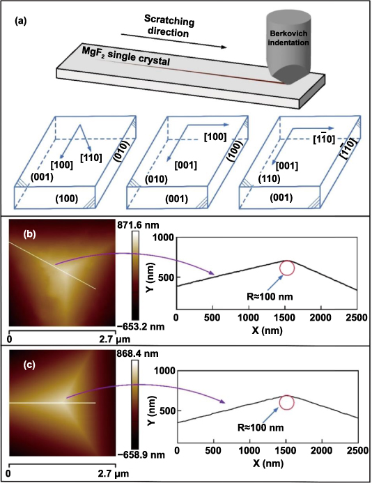
Figure 1. (a) Schematic diagram of scratch process, AFM images of indenter tip (b) before and (c) after scratch tests.
Download figure:
Standard image High-resolution imageTo study the effect of the anisotropy on the damage evolution and material removal behaviors, the scratch tests along different orientations were performed on three different crystal planes, namely, the (001), (010), and (110) planes. The scratch conditions are given in table 1 in detail. The mechanical properties of single crystal materials were distributed periodically and changed monotonically over half the change period. The change period of the mechanical properties on the (010) and (110) planes was 180°, and the change period of the mechanical properties on the (001) plane was 90°. The selected scratch directions were highly symmetrical and exhibited low exponential orientations. The included angle between the two scratch directions was half the change period. Therefore, the included angle between the two scratch directions was 90° on the (010) and (110) planes, and it was 45° on the (001) plane. To minimize the environment effect, the thermal drift rate was controlled within 0.5 nm s−1 during the scratch process. Each experiment was repeated thrice to ensure the accuracy of the experimental results. After the scratch experiment, the surface morphologies of the scratched grooves were observed using a SEM (SUPRA 55 SAPPHIRE, Germany). The AFM image of the indenter tip after the scratch tests is shown in figure 1(c), which indicates that the indenter tip is not broken during the scratch process.
Table 1. Experimental conditions.
| No. | Maximum load (mN) | Scratch speed (μm s−1) | Scratch length (μm) | Crystal plane | Scratching orientation |
|---|---|---|---|---|---|
| 1 ∼ 2 | 100 | 5 | 150 | (001) | [100], [110] |
| 3 ∼ 4 | 100 | 5 | 150 | (010) | [001], [100] |
| 5 ∼ 6 | 100 | 5 | 150 | (110) | [001], ![$\left[ {1\bar 10} \right]$](https://content.cld.iop.org/journals/2631-7990/5/1/015101/revision2/ijemac9eedieqn1.gif)
|
3. Results and discussions
3.1. The surface morphology
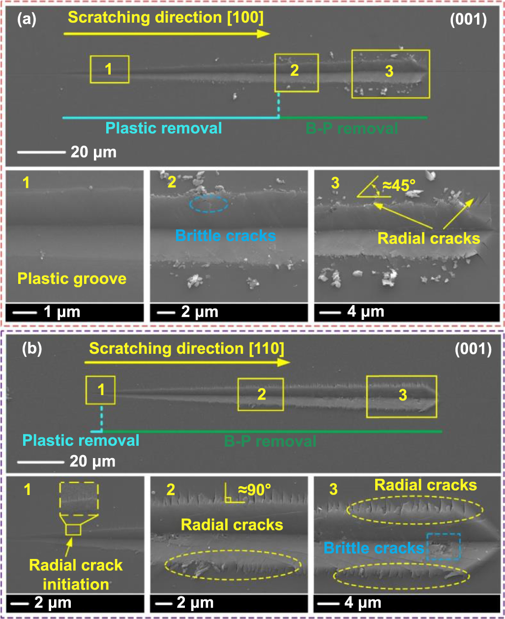
Figure 2 shows the surface morphologies of the scratched grooves along different crystal-orientations on the (001) plane of MgF2 crystals. Surface plastic removal is defined as a crack-free surface with obvious plastic upheaval or plastic flowing lines. As presented in figure 2(a), only a smooth groove with plastic deformation was generated at the beginning of the scratch along the [100] crystal-orientation. A surface crack was induced inside the groove as the normal load increased, and distinct radial cracks were generated on both sides of the groove when the normal load exceeded approximately 63.5 mN. The included angle between the scratch direction and radial cracks was approximately 45°. As shown in figure 2(b), for the scratch along the [110] crystal-orientation, a radial crack was induced when the normal load reached at approximately 4.5 mN, which was perpendicular to the scratch direction. Both the size and number of the radial cracks increased as the normal load increased, and brittle fractures occurred at the groove bottom at the end of the scratch. By comparing figures 2(a) and (b), it can be observed that more plastic deformation and fewer cracks were obtained when the scratch direction was along the [100] crystal-orientation, so the [100] crystal-orientation was more prone to achieving plastic deformation. Furthermore, all the radial cracks generated on the (001) crystal plane propagated along the [110] crystal-orientation. This occurred because {110} crystal planes are the cleavage planes of MgF2 single crystals [12] and cleavage fracture occurs when the tensile stress of the cleavage surface is sufficiently large. During the scratch process, the tensile stress of the cleavage planes caused by the tangential load when the scratch was along the [110] crystal-orientation was higher than that when the scratch was along the [100] crystal-orientation. Therefore, under the same scratch conditions, radial cracks were more easily generated when the scratch was along the [110] crystal-orientation.

Figure 2. SEM images of scratched groove morphology on (001) plane of MgF2 crystals along (a) [100] and (b) [110] crystal-orientations, (a1)–(a3) are partial enlarged images of (a), (b1)–(b3) are partial enlarged images of (b).
Download figure:
Standard image High-resolution imageFigure 3 shows the surface morphologies of the scratched grooves along different crystal-orientations on the (010) plane of MgF2 crystals. As presented in figure 3(a), a smooth groove with distinct plastic flowing lines was generated when the scratch was along the [001] crystal-orientation. The included angle between the scratch direction and plastic flow lines was approximately 60°. There were clear fluctuations in the penetration depth during the scratch process. Owing to the influence of the fluctuation of the penetration depth and pushing action of the Berkovich indenter, a plastic flow line is generated along the indenter edge during each fluctuation period. When the normal load reached at approximately 74.16 mN, the plastic deformation surface with plastic flowing lines suddenly changed to a brittle surface with chunk chips. As shown in figure 3(b), a smooth groove with distinct plastic flowing lines was also generated at the beginning of the scratch along the [100] crystal-orientation. When the normal load exceeded approximately 34.6 mN, microfracture occurred at the bottom of the scratched groove, but no surface cracks were observed on the bottom or groove side. When the normal load exceeded approximately 55.87 mN, brittle removal and chunk chips caused by the cleavage fracture occurred on the crystal surface. By comparing figures 3(a) and (b), it can be found that more plastic deformation and a larger brittle-to-plastic transition load were obtained when the scratch direction was along the [001] crystal-orientation, so the scratch along the [001] crystal-orientation was more prone to achieving plastic deformation than the [100] crystal-orientation.
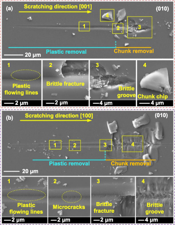
Figure 3. SEM images of scratched groove morphology on (010) plane of MgF2 crystals along (a) [001] and (b) [100] crystal-orientations, (a1)–(a4) are partial enlarged images of (a), (b1)–(b4) are partial enlarged images of (b).
Download figure:
Standard image High-resolution imageFigure 4 shows the surface morphologies of the scratched grooves along different crystal-orientations on the (110) plane of MgF2 crystals. As presented in figure 4(a), a smooth groove with distinct plastic flowing lines was generated under a low normal load when the scratch was along the [001] crystal-orientation. When the normal load reached at approximately 48.22 mN, the plastic deformation surface with plastic flowing lines suddenly changed to brittle removal with the chunk chips. As shown in figure 4(b), a smooth groove with plastic flowing lines was also generated at the beginning of the scratch along the ![$\left[ {1\bar 10} \right]$](https://content.cld.iop.org/journals/2631-7990/5/1/015101/revision2/ijemac9eedieqn2.gif) crystal-orientation. However, the length of the plastic deformation region was considerably short, and the plastic deformation surface with plastic flowing lines suddenly changed to a brittle surface with a large amount of chunk chips when the normal load exceeded approximately 14.15 mN. The size of the brittle chips and material fracture area also increased gradually as the normal load increased. Comparing figures 4(a) and (b), it can be found that more plastic deformation and larger brittle-to-plastic transition load were obtained when the scratch direction was along the [001] crystal-orientation, so the scratch along the [001] crystal-orientation was more prone to achieving plastic deformation than that along the
crystal-orientation. However, the length of the plastic deformation region was considerably short, and the plastic deformation surface with plastic flowing lines suddenly changed to a brittle surface with a large amount of chunk chips when the normal load exceeded approximately 14.15 mN. The size of the brittle chips and material fracture area also increased gradually as the normal load increased. Comparing figures 4(a) and (b), it can be found that more plastic deformation and larger brittle-to-plastic transition load were obtained when the scratch direction was along the [001] crystal-orientation, so the scratch along the [001] crystal-orientation was more prone to achieving plastic deformation than that along the ![$\left[ {1\bar 10} \right]$](https://content.cld.iop.org/journals/2631-7990/5/1/015101/revision2/ijemac9eedieqn3.gif) crystal-orientation.
crystal-orientation.
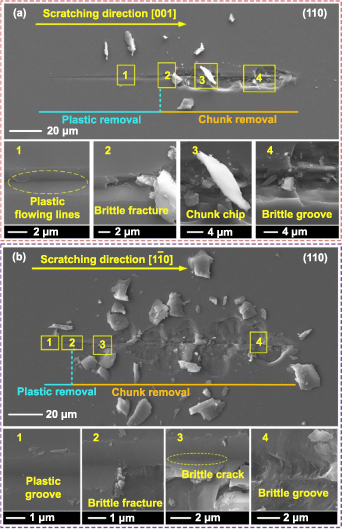
Figure 4. SEM images of scratched groove morphology on (110) plane of MgF2 crystals along (a) [001] and (b) ![$\left[ {1\bar 10} \right]$](https://content.cld.iop.org/journals/2631-7990/5/1/015101/revision2/ijemac9eedieqn4.gif) crystal-orientations, (a1)–(a4) are partial enlarged images of (a), (b1)–(b4) are partial enlarged images of (b).
crystal-orientations, (a1)–(a4) are partial enlarged images of (a), (b1)–(b4) are partial enlarged images of (b).
Download figure:
Standard image High-resolution imageThere were distinct differences in the surface morphology of the scratched grooves obtained from different crystal-planes and crystal-orientations, which demonstrated that the damage evolution and material removal behaviors of MgF2 single crystal had distinct anisotropy dependence. The above experimental results indicated that the plasticity of the (001) crystal plane was evidently better than that of the (010) and (110) crystal planes. The plastic deformation area of the (001) crystal plane along the [100] crystal-orientation was the largest, and the brittle fracture of the (110) crystal plane along the ![$\left[ {1\bar 10} \right]$](https://content.cld.iop.org/journals/2631-7990/5/1/015101/revision2/ijemac9eedieqn5.gif) crystal-orientation was the most serious. This phenomenon will be discussed in sections 3.2 and 3.3 in detail. Brittle fracture deteriorates the surface integrity of work materials, reducing the service accuracy as well as the service life of the crystal components. Therefore, it is particularly important to theoretically explain the brittle removal process of the work materials and put forward effective methods to improve the plastic deformation of the work materials. A considerable number of studies have demonstrated that brittle fracture behavior is closely related to the stress field distribution induced by the cutting tools [22–25]. Therefore, it is necessary to develop a theoretical model of the stress field, through which we can further understand the brittle removal process of brittle materials in depth, and put forward effective methods to inhibit the crack propagation and brittle fracture.
crystal-orientation was the most serious. This phenomenon will be discussed in sections 3.2 and 3.3 in detail. Brittle fracture deteriorates the surface integrity of work materials, reducing the service accuracy as well as the service life of the crystal components. Therefore, it is particularly important to theoretically explain the brittle removal process of the work materials and put forward effective methods to improve the plastic deformation of the work materials. A considerable number of studies have demonstrated that brittle fracture behavior is closely related to the stress field distribution induced by the cutting tools [22–25]. Therefore, it is necessary to develop a theoretical model of the stress field, through which we can further understand the brittle removal process of brittle materials in depth, and put forward effective methods to inhibit the crack propagation and brittle fracture.
3.2. Stress field induced by the scratch
Surface and subsurface cracks were generated during the brittle removal process of hard and brittle materials [26]. As shown in figure 5(a), radial cracks were generated at the side of the scratched groove, while median and lateral cracks were generated at the subsurface of the groove. As shown in figure 5(b), a plastic deformation region with radius h was generated underneath the indenter, and brittle removal occurred when the lateral cracks propagated to the surface of the work material [27].
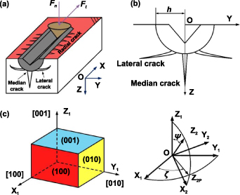
Figure 5. (a) Diagrammatic sketch of the single-grit scratch process, (b) cross-section of (a) perpendicular to the scratch direction, (c) orthogonal coordinate system (X1, Y1, Z1) and laboratory coordinate system (X2, Y2, Z2).
Download figure:
Standard image High-resolution imageThe overall stress field induced by the scratch can be regarded as the sum of the stress field induced by the normal load, the stress field induced by the tangential load and the residual stress field induced by the plastic deformation. To facilitate the analysis of the elastic stress field, the normal and tangential loads were simplified as a concentrated force acting on the origin point O. Therefore, the elastic stress fields caused by the normal and tangential loads can be transformed into the stress fields caused by a concentrated force acting on a point on the surface of a semi-infinite elastic body. Boussinesq stress field and Cerruti stress field express the stress distribution when the normal and tangential loads act on the surface of a semi-infinite elastic body, respectively. Therefore, Boussinesq stress field and Cerruti stress field were selected to calculate the elastic stress fields induced by the normal and tangential loads, respectively. The stress field induced by a normal load can be calculated by Boussinesq stress field [28, 29], which is given by equation (1),
where Fn is the normal load, σ is the normal stress, τ is the shear stress, ν is the Poisson's ratio, r2 = x2 + y2, and ρ2 = x2 + y2 + z2.
The stress field induced by the tangential load can be calculated by Cerruti stress field [28, 29], which is given by equation (2),
where Ft is the tangential load.
Yoffe found that the residual stress field induced by the plastic deformation was proportional to 1/r3. The plastic deformation region induced by the scratch process can be approximately a hemispherical region. Blister stress field refers to a stress field which describes the hemispherical residual stress distribution, so it can be used to calculate the residual stress field induced by the scratch process [29, 30]. The residual stress field can be expressed by equation (3),
where BS is the sliding strength per scratch length [31], as determined by equation (4),
where E is the elastic modulus of MgF2 crystals, H is the hardness of MgF2 crystals, and α is the equivalent half-apex angle which is 65.3° for the Berkovich indenter. η is a dimensionless geometric factor, whose value is only related to the geometry of the indenter and independent of the work material and is 1.25 for Berkovich indenter [23, 31]. f is the compaction factor, and f·E/H is equal to tanκ/2, where κ is the equivalent half-apex angle of the indenter. The equivalent half-apex angle of the Berkovich indenter is 65.3°. Therefore, f·E/H = 1.09 in this work. The value of 1.09 is only related to the geometry of the indenter and is independent of the work material.
The overall stress field induced by the scratch can be calculated by combining equations (1)–(4), as given in equation (5),
To consider the mechanical anisotropy of MgF2 single crystals in the stress field model, the elastic modulus, hardness and Poisson's ratio of different crystal planes should be obtained. The elastic modulus of (hkl) plane, E(hkl), can be determined the flexibility matrix S, calculated by equation (6),
where C is the stiffness matrix; c11, c12, c13, c33, c44 and c66 are elastic coefficients of the stiffness matrix; and s11, s12, s13, s33, s44 and s66 are flexibility coefficients of the flexibility matrix. For MgF2 single crystals, c11 = 140.22 GPa, c12 = 89.50 GPa, c13 = 62.90 GPa, c33 = 204.65 GPa, c44 = 56.76 GPa and c66 = 95.70 GPa [32].
The elastic modulus of (hkl) plane of MgF2 single crystals, E(hkl), can be expressed by equation (7) [33],
where a, b, and c are lattice constants of the work materials. For MgF2 single crystals, a= b= 4.631 Å, and c= 3.057 Å [34].
To calculate the Poisson's ratio of the (hkl) crystal plane of MgF2 single crystals, ν(hkl), the orthogonal and laboratory coordinate systems were developed, as shown in figure 5(c). Through the flexibility coefficients of the flexibility matrix in the orthogonal coordinate system, the Poisson's ratio of the (001) crystal plane which is perpendicular to the Z1 axis can be calculated. However, the normal vectors of other (hkl) crystal planes cannot be obtained using only the orthogonal coordinate system. Therefore, we should develop a laboratory coordinate system to obtain the normal vectors of the other (hkl) crystal planes. The matrix g describes the relationship between the orthogonal and laboratory coordinate systems, as given in equation (8),
where ψ is the included angle between the Z1 axis and Z2 axis, and ζ is the included angle between the X1 axis and Z2P axis which is the projection of the Z2 axis on the X1 OY1 plane. The ξ values of the (001), (010) and (110) crystal planes are 0°, 90° and 45°, respectively. The ψ values of the (001), (010) and (110) crystal planes are 0°, 90° and 90°, respectively.
When the Z2 axis is perpendicular to (hkl) crystal plane, ν(hkl), can be expressed by equation (9) [35],

The surface morphology of the scratch grooves demonstrated distinct brittle fracture behaviors on the (010) and (110) crystal planes, so the stress fields of the (010) and (110) crystal planes were analyzed. The detailed parameters used in the simulations are listed in table 2. The hardness parameters in table 2 were measured using the nanoindentation tests. The critical scratch distance when the brittle fracture occurs can be determined from the surface morphologies of the scratches. The normal and tangential loads when the brittle fracture occurs can be obtained according to the critical scratch distance and the load-distance curve recorded by the nanoindenter. The values of the normal and tangential loads in table 2 are the average values of the three tests. The scratch direction is not directly reflected in the stress model. The scratch direction is related to the normal load Fn, tangential load Ft and cutting depth d. The values of Fn, Ft and d under different scratch directions are listed in table 2. The stress can be calculated by applying these parameters to equations (1)–(5).
Table 2. Parameters of stress simulation.
| No. | Fn (mN) | Ft (mN) | Depth (nm) | Hardness (GPa) | Crystal plane | Scratching orientation |
|---|---|---|---|---|---|---|
| 1 | 74.16 | 16.65 | 669.08 | 6.78 | (010) | [001] |
| 2 | 55.87 | 10.10 | 746.13 | 6.78 | (010) | [100] |
| 3 | 48.22 | 9.64 | 548.37 | 7.38 | (110) | [001] |
| 4 | 14.15 | 2.19 | 305.31 | 7.38 | (110) |
![$\left[ {1\bar 10} \right]$](https://content.cld.iop.org/journals/2631-7990/5/1/015101/revision2/ijemac9eedieqn6.gif)
|
During the scratch process of brittle materials, the initiation and propagation of the cracks were determined by the stresses σx, σy and σz [35]. To simplify the analysis of the stress field distribution, the calculated stress field was normalized as σd2/Fn, where d is the scratch depth. Since the distribution forms of all stress fields are similar, only the stress field of the (010) crystal plane along the [100] crystal-orientation was analyzed in detail. Figure 6 shows the normalized stress field in the XOZ plane when brittle removal occurred in the scratch of the (010) crystal plane along the [100] crystal-orientation. The front of the indenter is defined as the scratch area in front of the two rake faces of the indenter, and the area behind of the indenter is defined as the scratch area behind the flank face of the indenter. As shown in figure 6(a), the stress at the front of the indenter is compressive stress, and the stress behind the indenter is tensile stress. The stress behind the indenter decreases rapidly with the increase of the distance from the scratched surface, indicating that there is a distinct stress concentration of σx on the scratched surface. According to the direction of the tensile stress σx , it can be concluded that surface radial cracks induced by the tensile stress are easily generated on the surface during the unloading process. As shown in figure 6(b), the stress at the front of the indenter is tensile stress, which is induced by the expansion of the material at the front of the indenter to both sides during the scratch process. According to the direction of the tensile stress σy , it can be concluded that the median cracks induced by the tensile stress initiate and propagate at the front of the indenter. The gradient direction of the tensile stress σy follows obliquely along the Z direction, which affects the direction of median crack propagation. Because the stress behind the indenter is compressive stress, the unloading process inhibits the propagation of the median crack. Figure 6(c) shows that the contours of the tensile stress σz behind the indenter are parallel, and there is a distinct stress concentration of σz on the scratched surface. Because σz is much higher than σx and σy , and σz can induce the propagation of the lateral cracks, the unloading process further makes the lateral cracks propagate on the subsurface. The stress in front of the indenter belongs to elastic stress, and the stress behind the indenter belongs to residual stress. It can be concluded that the residual tensile stress behind the indenter induces radial and lateral cracks during the unloading process, and the tensile stress (elastic stress) in front of the indenter induces median crack during the loading process. Brittle removal caused by the lateral cracks seriously reduces the surface quality of the workpiece [27], and the generation of the lateral crack is related to the stress behind the indenter [36]. Therefore, to further understand the initiation and propagation of the lateral crack, the stress field of the plane in x/d = −0.5 was analyzed.

Figure 6. Normalized stress field in XOZ plane when brittle removal occurred in the scratch of (010) crystal plane along [100] crystal-orientation (a) stress σx , (b) stress σy and (c) stress σz.
Download figure:
Standard image High-resolution imageFigure 7 shows the normalized stress field of the plane in x/d= −0.5 during the unloading process of the indenter. Figures 7(a) and (c) indicate that the maximum tensile stresses of σx and σz appear underneath the indenter. Figure 7(a) shows that during the unloading process, the tensile stress of σx caused by the residual stress is concentrated on the surface of the scratched groove, which further indicates that the tensile stress of σx may induce the initiation of surface radial cracks perpendicular to the scratch direction. Figure 7(b) indicates that the maximum tensile stress of σy appears on the surface of the scratched groove. If the tensile stress of σy is sufficiently large, it may induce the initiation of surface cracks inside the scratched groove, such as the surface cracks in figure 2(b3). According to the action position and direction of the tensile stress in figure 7(c), it can be concluded that the tensile stress σz induces the initiation of the lateral cracks underneath the indenter, and then the lateral cracks propagate to both sides of the groove along the Y direction. As the lateral cracks propagate to both sides of the indenter, the effect of σz on lateral cracks decreases gradually, whereas the effect of σy on lateral cracks gradually increases. This leads to the deflection of the propagation direction of lateral cracks, such that the lateral cracks propagate to the workpiece surface and result in brittle removal in the form of chunk chips [37]. In addition, the tensile stress of σz is higher than the tensile stresses of σx and σy . Therefore, during the unloading process, the effect of tensile stress σz on the crack initiation and propagation is more significant than that of the tensile stresses σx and σy .
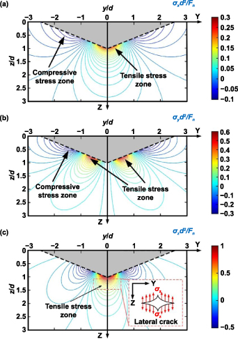
Figure 7. Normalized stress field of the plane in x/d= −0.5 when brittle removal occurred in the scratch of (010) crystal plane along [100] crystal-orientation (a) stress σx , (b) stress σy and (c) stress σz.
Download figure:
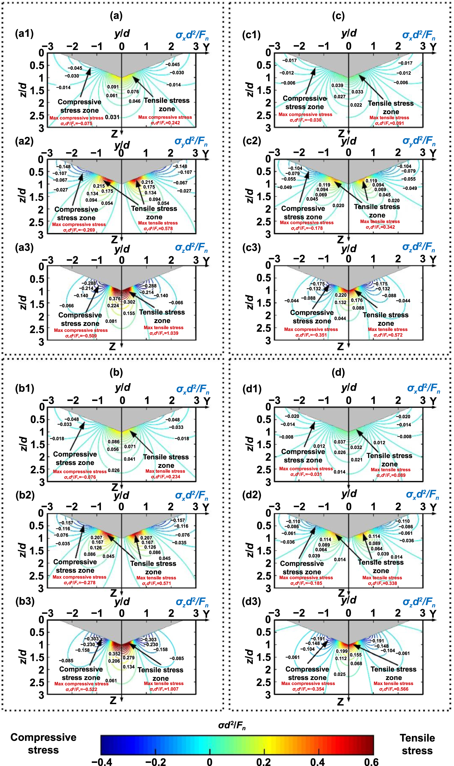
Standard image High-resolution imageFigure 8 shows the normalized stress field of the plane in x/d = −0.5 when brittle removal occurs in the scratches under different crystal planes and crystal-orientations. Figures 8(a) and (b) show that the distribution pattern of the normalized stress field in the scratch of (010) plane along [001] crystal-orientation is similar to that in the scratch of the (010) plane along the [100] crystal-orientation. Figures 8(c) and (d) show that the distribution pattern of the normalized stress field in the scratch of the (110) plane along the [001] crystal-orientation is similar to that in the scratch of the (110) plane along the ![$\left[ {1\bar 10} \right]$](https://content.cld.iop.org/journals/2631-7990/5/1/015101/revision2/ijemac9eedieqn7.gif) crystal-orientation. It can be concluded that for tetragonal crystals, the stress field distributions on the same scratch planes along different crystal-orientations are similar. Comparing figures 8(a) and (c), it can be found that both tensile stress and compressive stress in the scratch of (010) plane along [001] crystal-orientation are much higher than that in the scratch of (110) plane along [001] crystal-orientation. Comparing figures 8(b) and (d), it can be observed that both the tensile and compressive stresses in the scratch of the (010) plane along the [100] crystal-orientation are much higher than those in the scratch of the (110) plane along the
crystal-orientation. It can be concluded that for tetragonal crystals, the stress field distributions on the same scratch planes along different crystal-orientations are similar. Comparing figures 8(a) and (c), it can be found that both tensile stress and compressive stress in the scratch of (010) plane along [001] crystal-orientation are much higher than that in the scratch of (110) plane along [001] crystal-orientation. Comparing figures 8(b) and (d), it can be observed that both the tensile and compressive stresses in the scratch of the (010) plane along the [100] crystal-orientation are much higher than those in the scratch of the (110) plane along the ![$\left[ {1\bar 10} \right]$](https://content.cld.iop.org/journals/2631-7990/5/1/015101/revision2/ijemac9eedieqn8.gif) crystal-orientation. It can be concluded that for the same scratch direction, the stress of the (010) crystal plane is much higher than that of the (110) crystal plane. Therefore, when brittle removal occurs, the acquired stress of the (010) crystal plane is much higher than that of the (110) crystal plane. From figure 8, it can be also found that the tensile stress is higher than the compressive stress during the unloading process. Therefore, tensile stress can easily induce brittle fractures during the unloading process.
crystal-orientation. It can be concluded that for the same scratch direction, the stress of the (010) crystal plane is much higher than that of the (110) crystal plane. Therefore, when brittle removal occurs, the acquired stress of the (010) crystal plane is much higher than that of the (110) crystal plane. From figure 8, it can be also found that the tensile stress is higher than the compressive stress during the unloading process. Therefore, tensile stress can easily induce brittle fractures during the unloading process.
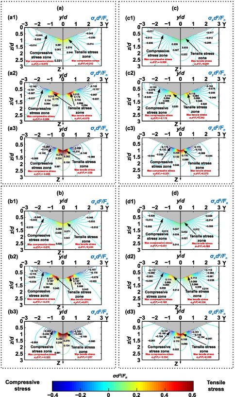
Figure 8. Normalized stress field of the plane in x/d = −0.5 when brittle removal occurs in the scratch of (a) (010) plane along [001] crystal-orientation, (b) (010) plane along [100] crystal-orientation, (c) (110) plane along [001] crystal-orientation, (d) (110) plane along ![$\left[ {1\bar 10} \right]$](https://content.cld.iop.org/journals/2631-7990/5/1/015101/revision2/ijemac9eedieqn9.gif) crystal-orientation.
crystal-orientation.
Download figure:
Standard image High-resolution image3.3. Anisotropy effect on damage evolution induced by crystal-plane slip
In sections 3.1 and 3.2, it is demonstrated that the plastic deformation of crystal materials is dominated by crystal-plane slip and that scratched crystal planes and crystal directions have a significant effect on the stress field distribution [38, 39]. This section will focus on the anisotropy effect on the damage evolution induced by cleavage fracture and slip deformation. Figure 9(a) is the schematic diagram of the cleavage fracture of MgF2 single crystals, where the resolved tensile stress σk is the driving stress acting on the cleavage plane, as given in equation (10),

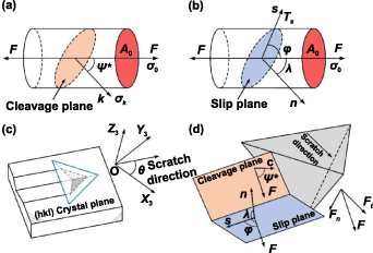
Figure 9. Diagrammatic sketch of (a) cleavage fracture, (b) crystal slip during the tensile process, (c) scratch coordinate system O-X3 Y3 Z3, and (d) relationship among action force F, slip system and cleavage plane.
Download figure:
Standard image High-resolution imagewhere σ0 is the average stress acting on the cross-section A0; m is the cleavage factor, which reflects the degree of difficulty of the cleavage fracture which can be calculated as m= cos2 ψ*; and ψ* is the included angle between the applied force F and the normal line of the cleavage plane k.
Different cleavage planes have different fracture energies, and the cleavage fracture parameter Q was proposed to quantitatively analyze the activation degree of the cleavage plane [40]. The cleavage fracture parameter of the jth cleavage plane Qj can be expressed using equation (11),
where mj
is the cleavage factor of the jth cleavage plane, Ej
is the fracture energy of the jth cleavage plane, minEj
is the minimum fracture energy. The (110) plane and ![$\left[ {1\bar 10} \right]$](https://content.cld.iop.org/journals/2631-7990/5/1/015101/revision2/ijemac9eedieqn10.gif) plane are the cleavage planes of MgF2 single crystals [21].
plane are the cleavage planes of MgF2 single crystals [21].
Figure 9(b) is the schematic diagram of the crystal slip during the tensile process, where resolved shear stress τs is the driving stress of the crystal slip, as given in equation (12),

where μ is Schmid factor which can be calculated as cosλ·cosϕ, λ is the included angle between the pulling force F and normal line n of the slip plane, ϕ is the included angle between the pulling force F and slip direction s. When shear stress τs reaches at the critical resolved shear stress τc, the slip deformation will occur. Nowak [21] proposed plastic deformation parameter P to quantitatively analyze the activation degree of the slip deformation. The plastic deformation parameter of the ith slip system Pi can be expressed by equation (13),
where μi
is the Schmid factor of the ith slip system, τi
c is the critical resolved shear stress of the ith slip system, and minτi
c is the minimum critical resolved shear stress. The primary slip systems of MgF2 single crystals are (110)/[001] and  /[001], and the secondary slip systems of MgF2 single crystals are (001)/[100] and (001)/[010] [13, 40]. The parameters of the critical shear stress of MgF2 single crystals are listed in table 3.
Table 3. Parameters of slip systems for MgF2 single crystals [40].
| Slip System No. | Slip System | τci /minτ c i |
|---|---|---|
| 1 | (110)/[001] | 1 |
| 2 |
 /[001] /[001] | 1 |
| 3 | (001)/[100] | 5 |
| 4 | (001)/[010] | 5 |
As shown in figure 9(c), a scratch coordinate system O-X3
Y3
Z3 was developed to calculate the plastic deformation and cleavage fracture parameters. Axis Z3 is perpendicular to the crystal plane (hkl). Axis X3 can be in any direction on the scratched plane. For the crystal direction analyzed in this work to be oriented in the middle of figures 10–12 as much as possible, axis X3 is set to be parallel to the ![$\left[ {\bar 100} \right]$](https://content.cld.iop.org/journals/2631-7990/5/1/015101/revision2/ijemac9eedieqn13.gif) crystalline orientation when the scratch plane is (001) crystal plane, and it is parallel to
crystalline orientation when the scratch plane is (001) crystal plane, and it is parallel to ![$\left[ {00\bar 1} \right]$](https://content.cld.iop.org/journals/2631-7990/5/1/015101/revision2/ijemac9eedieqn14.gif) crystalline orientation when the scratch planes are (010) and (110) crystal planes. The included angle between the scratch direction and axis X3 is θ. Figure 9(d) shows the relationship among the action force F, slip system and cleavage plane. The plastic deformation parameter Pi
and cleavage fracture parameter Qj
under different scratch conditions can be calculated by equation (14),
crystalline orientation when the scratch planes are (010) and (110) crystal planes. The included angle between the scratch direction and axis X3 is θ. Figure 9(d) shows the relationship among the action force F, slip system and cleavage plane. The plastic deformation parameter Pi
and cleavage fracture parameter Qj
under different scratch conditions can be calculated by equation (14),

Figure 10. (a) Calculated plastic deformation parameter of (001) plane, (b) calculated cleavage fracture parameter of (001) plane, (c) and (d) positional relationship between the scratch direction and cleavage planes.
Download figure:
Standard image High-resolution image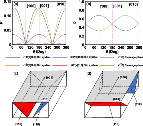
Figure 11. (a) Calculated plastic deformation parameter of (010) plane, (b) calculated cleavage fracture parameter of (010) plane, (c) and (d) positional relationship between the scratch direction and cleavage planes.
Download figure:
Standard image High-resolution image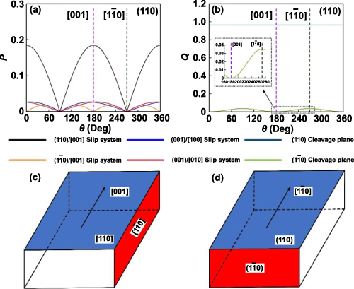
Figure 12. (a) Calculated plastic deformation parameter of (110) plane, (b) calculated cleavage fracture parameter of (110) plane, (c) and (d) positional relationship between the scratch direction and cleavage planes.
Download figure:
Standard image High-resolution imagewhere  ,
,  ,
,  and
and  are the unit vectors of axis X3, axis Y3, axis Z3, and slip direction i, respectively.
  and
and  are the normal unit vectors of the ith slip plane and the jth cleavage plane, respectively. P and Q reflect the difficulty of the slip deformation and cleavage fracture of the crystals. The higher the P value, the easier the occurrence of slip deformation in the slip systems. The higher the Q value, the easier the occurrence of cleavage fracture on the cleavage planes.
The calculated results of plastic deformation and cleavage fracture parameters on the (001) planes are shown in figures 10(a) and (b), respectively. Figure 10(a) shows that the scratch along the [100] crystal-orientation activates (110)/[001] and  /[001] slip systems, and the scratch along the [110] crystal-orientation activates (110)/[001] slip system. Although (001)/[100] slip system may be activated when the scratch along the [100] crystal-orientation and (001)/[100] and (001)/[010] slip systems may be activated when the scratch along the [110] crystal-orientation, the plastic deformation parameter of (001)/[100] and (001)/[010] slip systems are much lower than that of (110)/[001] and
  /[001] slip systems. The activating possibility of (001)/[100] and (001)/[010] slip systems is much lower than that of (110)/[001] and
  /[001] slip systems. Considerable amount of literature demonstrates that the slip systems with low plastic deformation parameters can be neglected in the analysis of the crystal slip [39, 40]. The more slip systems that are activated, the more easily plastic deformation occurs [41, 42]. Therefore, plastic deformation is more likely to occur during the scratch along the [100] crystal-orientation. Figure 10(b) shows that the maximum cleavage fracture parameter along the [100] crystal-orientation is much lower than that along the [110] crystal-orientation, indicating that cleavage fracture is not easy to occur when the scratch is along the [100] crystal-orientation. The above theoretical calculation can reasonably explain the experimental results in figure 2, i.e. more plastic deformation and higher brittle-to-plastic transition load occurred in the scratch along the [100] crystal-orientation. Figure 10(c) shows that the included angle between the [100] crystal-orientation and the activated cleavage planes is 45°, therefore, the included angle between the [100] crystal-orientation and propagation direction of radial cracks is 45°. Figure 10(d) shows that the included angle between the [110] crystal-orientation and the activated cleavage planes is 90°, therefore, the included angle between the [110] crystal-orientation and propagation direction of radial cracks is 90°. It can be concluded that the radial cracks on the scratched surface propagated along the activated cleavage planes, which is consistent with the experimental results in figure 2.
The calculated results of plastic deformation and cleavage fracture parameters on the (010) planes are shown in figures 11(a) and (b), respectively. Figure 11(a) shows that the scratch along the [001] crystal-orientation activates (110)/[001] and  /[001] slip systems, but the scratch along the [100] crystal-orientation does not activate any slip system. The scratch along the [001] crystal-orientation activates more slip systems than that along the [100] crystal-orientation, resulting in more plastic deformation in the scratch along the [001] crystal-orientation. Figure 11(b) shows that the maximum cleavage fracture parameter along the [001] crystal-orientation is much lower than that along the [100] crystal-orientation, indicating that cleavage fracture is easier to occur when the scratch is along the [100] crystal-orientation. The above theoretical calculation can reasonably explain the experimental results in figure 3, i.e. more plastic deformation and higher brittle-to-plastic transition load occurred in the scratch along the [001] crystal-orientation. Figure 11(c) shows the positional relationship between the [001] crystal-orientation and cleavage planes, indicating that the activated cleavage planes are on both sides of the scratch direction. Therefore, the cracks propagate along both sides of the scratched groove, resulting in the brittle chunk removal when the scratch is along the [001] crystal-orientation. Figure 11(d) shows the positional relationship between the [100] crystal-orientation and cleavage planes, indicating that the activated cleavage planes are in front of the scratch direction. Therefore, the cracks propagate along the scratch direction and result in the brittle chunk removal when the scratch is along the [100] crystal-orientation. The theoretical results are consistent with the experimental results, which further demonstrates that the cracks propagate along the activated cleavage planes.
The calculated results of plastic deformation and cleavage fracture parameters on the (110) planes are shown in figures 12(a) and (b), respectively. Figure 12(a) shows that the scratch along the [001] crystal-orientation activates (110)/[001] slip system, whereas the scratch along the ![$\left[ {1\bar 10} \right]$](https://content.cld.iop.org/journals/2631-7990/5/1/015101/revision2/ijemac9eedieqn25.gif) crystal-orientation does not activate any slip system. Figure 12(b) shows that both the scratches along the [001] and
crystal-orientation does not activate any slip system. Figure 12(b) shows that both the scratches along the [001] and ![$\left[ {1\bar 10} \right]$](https://content.cld.iop.org/journals/2631-7990/5/1/015101/revision2/ijemac9eedieqn26.gif) crystal-orientations activate (110) cleavage planes, and the cleavage fracture parameters under the two conditions are the same. As the [001] crystal direction activates slip deformation more easily, plastic removal proportion and brittle-to-plastic transition load in the scratch along the [001] crystal crystal-orientation are higher. As the increase of the scratch load and normal stress acted on the cleavage plane, the deformation mode gradually changes from plastic slip to brittle cleavage fracture. In addition, the fracture morphologies of the scratched surface are also consistent with the cleavage fracture results. The above results can reasonably explain the experimental results in figure 4.
crystal-orientations activate (110) cleavage planes, and the cleavage fracture parameters under the two conditions are the same. As the [001] crystal direction activates slip deformation more easily, plastic removal proportion and brittle-to-plastic transition load in the scratch along the [001] crystal crystal-orientation are higher. As the increase of the scratch load and normal stress acted on the cleavage plane, the deformation mode gradually changes from plastic slip to brittle cleavage fracture. In addition, the fracture morphologies of the scratched surface are also consistent with the cleavage fracture results. The above results can reasonably explain the experimental results in figure 4.
The calculated results show that the (001) and (110) planes have the minimum and maximum cleavage fracture parameters, respectively. The larger the cleavage fracture parameter, the more prone the crystal is to brittle cleavage fractures. Therefore, under the same processing parameters, no chunk removal occurred on the (001) crystal plane, whereas the most serious brittle fracture occurred on the (110) crystal plane. Both theoretical and experimental results demonstrate that the anisotropy has a significant influence on the damage evolution in the processing process of brittle single crystals, and selecting the optimized processing direction is helpful in realizing the high-efficiency and low-damage processing of brittle single crystals [43].
4. Conclusions
Nanoscratch tests of MgF2 single crystals of different crystal planes and directions were systematically performed, and the surface morphologies of the scratched grooves under different conditions were analyzed. To further understand the anisotropy dependence of the damage evolution and material removal during the machining of MgF2 single crystals, a stress field model was developed, and the plastic deformation and cleavage fracture parameters under different scratch conditions were calculated. The following conclusions can be drawn regarding the influence of the anisotropy on the nano-scale machining of MgF2 single crystals.
- Experimental results demonstrated that the anisotropy had a significant influence on the damage evolution and material removal behaviors in the machining process of MgF2 single crystals. Serious cleavage fracture occurred on the scratched surfaces of the (010) and (110) planes when the scratch load was sufficiently large. Under the maximum normal load of 150 mN and the selected scratch directions in this work, no chunk removal occurred on the scratched surface of the (001) plane. Cleavage fractures might occur on the scratched surface of the (001) plane when the scratch load is sufficiently large.
- The stress field model induced by the scratch was developed by considering the anisotropy, which indicated that median cracks induced by the tensile stress initiated and propagated at the front of the indenter during the loading process. The lateral cracks induced by the tensile stress initiated and propagated on the subsurface during the unloading process. In addition, surface radial cracks induced by the tensile stress were easily generated during the unloading process. The stress change led to the deflection of the propagation direction of lateral cracks, so that the lateral cracks propagated to the workpiece surface and resulted in brittle removal in the form of chunk chips.
- The theoretical results of the plastic deformation parameter indicated that under the same processing conditions, the more slip systems were activated, the more easily plastic deformation occurred. The theoretical results of the cleavage fracture parameter indicated that the cracks propagated along the activated cleavage planes, and brittle chunk removal was caused by subsurface cleavage cracks propagating to the crystal surface. Under the same processing parameters, the scratch of the (001) crystal plane along the [100] crystal-orientation activated most slip systems and had the minimum cleavage fracture parameter, so it was found to be the most conducive to achieving the plastic machining of MgF2 single crystals. However, the scratch of the (110) planes along the
![$\left[ {1\bar 10} \right]$](data:image/png;base64,iVBORw0KGgoAAAANSUhEUgAAAAEAAAABCAQAAAC1HAwCAAAAC0lEQVR42mNkYAAAAAYAAjCB0C8AAAAASUVORK5CYII=) crystal-orientation did not activate any slip system and had the maximum cleavage fracture parameter, so the most serious brittle fracture occurred on the (110) crystal plane along the crystal-orientation.
crystal-orientation did not activate any slip system and had the maximum cleavage fracture parameter, so the most serious brittle fracture occurred on the (110) crystal plane along the crystal-orientation. - The theoretical results agreed well with the experimental results, thereby providing a theoretical foundation for achieving the high-efficiency and low-damage processing of anisotropic crystal materials.
![$\left[ {1\bar 10} \right]$](https://content.cld.iop.org/journals/2631-7990/5/1/015101/revision2/ijemac9eedieqn27.gif)
![$\left[ {1\bar 10} \right]$](https://content.cld.iop.org/journals/2631-7990/5/1/015101/revision2/ijemac9eedieqn28.gif)
Acknowledgments
This work was supported by the National Natural Science Foundation of China (52005134 & 51975154), China Postdoctoral Science Foundation (2022T150163, 2020M670901), Self-Planned Task (No. SKLRS202214B) of State Key Laboratory of Robotics and System (HIT), Heilongjiang Postdoctoral Fund (LBH-Z20016), Shenzhen Science and Technology Program (GJHZ20210705142804012), Fundamental Research Funds for the Central Universities (FRFCU5710051122), and Open Fund of ZJUT Xinchang Research Institute.
Data availability statement
The datasets generated and analyzed during the current study are available from the corresponding author upon reasonable request.