
Abstract
The magnetorheological honing process is developed to meet the industrial needs of the inner surface nano-finishing of cylindrical components with different diameters. The process utilizes the magnetorheological honing tool which constitutes four radial polarized curved permanent magnet strips. The outer surface of the MR honing tool i.e. curved permanent magnet strips has the flexibility to move radially inwards or outwards according to the requirement of the diameter of the cylindrical inner surface to be finished. In the present paper, the response surface methodology is utilized to plan and evaluate the effects of various process variables on percentage change in surface roughness (Ra) value for the finishing of EN-31 cylindrical workpieces. The EN-31 material has its extensive applications in industry for manufacturing cylindrical dies and moulds for various cylindrical plastic products. The experimental analysis concluded that the percentage change in Ra value is mostly contributed by the working gap succeeded by the MR honing tool rotational speed, the percentage concentration of SiC particles, the MR honing tool reciprocation speed and the percentage concentration of carbonyl iron particles. With the identified optimum process parameters, experimentations have been performed and least Ra value of 95 nm is obtained from the initial value of 476 nm in finishing time of 120 min. Further to observe the finishing performed by the process over the surface, the scanning electron microscopy (SEM) test is performed.
Export citation and abstract BibTeX RIS
1. Introduction
Today's industries demand the very precisely finished industrial components to meet their high-end applications [1]. There are various industries which require highly precise finished internal cylindrical surface with good surface integrity like injection molding, hydraulic cylinders and cylindrical dies and molds etc [2]. These industries require highly finished surfaces for having benefits like dimensional accuracy, closer tolerance fit or design, increased tool life and decrease in wear and frictional losses etc. Finishing of components which need higher accuracy is a very difficult and time taking task in manufacturing industry [3]. The conventional finishing operations like grinding or honing are incapable to result in the required finish with good surface integrity. These processes make use of rigid tools for finishing due to which they do not have control over finishing forces [4]. Because of this, these processes sometimes may result with certain problems like surface crack formation, deeper grooves, sharper edges and residual stresses etc due to the high quantity of heat generation [5]. These surface defects may lead to the decrease in operational capability of industrial products. Various aerospace and automotive products demand highly finished cylindrical surfaces for their dies and molds [6]. The problem of intermixing of different colours while manufacturing the products through the defective molds may rise a blunder problem [7]. Defects in molds may lead to rejection of products which affects the overall productivity and profits of the industry.
To conquer the constraints of conventional finishing operations and to achieve nano-finished surface over the inner side of the cylindrical components, the advance controllable processes based on magnetorheological (MR) polishing fluid are developed by the researchers. Magnetorheological abrasive flow finishing (MRAFF) [8] and rotational-magnetorheological abrasive flow finishing (R-MRAFF) [9] are the finishing processes which make use of smart fluid called MR polishing fluid and have been evolved for the cylindrical internal surfaces. The MR polishing fluid is generally a mixer of micron-sized magnetic particles in a viscous base medium like water, paraffin oil or glycerol [10, 11] with some stabilizers and surfactants for governing the wear rate and corrosion [12]. The most advantageous benefit of MR polishing fluid is that its rheological properties can be altered easily by regulating the magnetic field in the area where it is being used [13, 14]. The normal force acting by the active abrasives of MR polishing fluid to shear the workpiece surface material can be easily regulated by altering the supply of magnetic field. Various advanced finishing processes like magnetorheological abrasive honing process (MRAH) [15], ball end magnetorheological finishing process (BEMRF) [16], magnetorheological honing process (MRH) using electromagnet core for particular internal diameter [17] and rotational magnetorheological honing (R-MRH) process [18] have been developed which make use of this property of MR polishing fluid for different surface finishing purposes. In MRH process [7], cylindrical workpiece is being kept stationary while in rotational magnetorheological honing process (R-MRH) [18], additional rotational movement is being provided to the cylindrical workpiece. In R-MRH process, interacted area of the active abrasive particles with the inner surface of cylindrical workpiece gets increased due to the additional rotational motion of the cylindrical workpiece as compared to the interacted area in MRH process. Optimum process parameters for rotational magnetorheological honing (R-MRH) process have been evaluated for better finishing performance [18]. Yamaguchi et al [19] performed finishing of the industrial used material by making use of magnetic field. Finishing processes like MRAFF [8] and R-MRAFF [9] are capable to finish only the non-ferromagnetic cylindrical workpieces. For attaining nano-finishing over the internal surface of cylindrical workpieces of variable diameters, a process named as the magnetorheological honing process has been developed [7]. The photograph of the developed MR honing process for variable cylindrical workpieces is shown in figure 1. The process consists of a MR honing tool having four radially polarized curved permanent magnet strips. These outer finishing surfaces of MR honing tool i.e. curved permanent magnets can move radially inwards or outwards about the central axis of the finishing tool. The outer diameter of the finishing tool can be altered according to the diameter of the cylindrical workpiece to be finished. The MR honing tool is mounted over the vertical Z- slide and rotated as well as reciprocated inside the cylindrical workpiece with the help of servomotors as shown in figure 1. The cylindrical workpiece is held with the help of grinding precision vice over the honeycomb breadboard. All the axial and rotational movements of the process are given through programmable logic controller (PLC). For the developed process, the maximum magnitude of magnetic flux density (B) is always present over the external surface of finishing tool in comparison with the ferromagnetic cylindrical workpiece's inner surface [7]. This difference in the magnitude of magnetic flux density (B) within the working region contributes to the finishing of the ferromagnetic cylindrical internal surface workpiece.
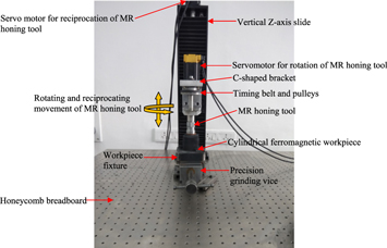
Figure 1. Photograph of the present developed magnetorheological honing setup during internal surface finishing of ferromagnetic EN-31 cylindrical workpieces.
Download figure:
Standard image High-resolution imageThe present MR honing tool moves inside the ferromagnetic cylindrical workpiece with maintaining a uniform gap for MR polishing fluid. When the MR honing tool gets rotated as well as reciprocated inside the cylindrical workpiece, the carbonyl iron particles (CIPs) make chains in the working gap (due to the induced magnetic field) and holds the SiC abrasives onto the cylindrical inner surface. The magnetic CIPs push the non-magnetic abrasives towards the ferromagnetic cylindrical workpiece's inner surface with levitation force and make them to move into the roughness peaks of the cylindrical workpiece's inner surface. The abrasives which are present on the inner surface and take part in finishing are called as the active abrasives. The material removal mechanism of MR honing process with the help of active abrasives is shown in figure 2. Active abrasives are strongly held and pushed by the CIPs chains towards the inner cylindrical surface with the indentation force (Fi). Due to the reciprocating motion of MR honing tool, the active abrasives are acted by an axial force (Fa) in the direction parallel to the central axis of finishing tool as shown in figure 2. Due to the rotating motion of MR honing tool, the active abrasives are acted by tangential force (Ft) in the direction of rotation of finishing tool as shown in figure 2. Fi is the force which is liable for indenting the abrasives into the surface of the workpiece and the Fa and Ft are the forces responsible for the shearing of peaks of surface roughness. In the present work, the optimum process parameters have been predicted in finishing the internal surface of the EN31 cylindrical workpieces using the magnetorheological honing (MRH) process [7] where the workpiece cylinder is being kept stationary.
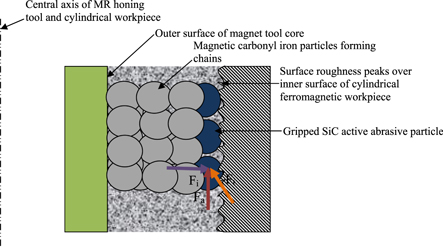
Figure 2. Mechanism of material removal while performing finishing with the present magnetorheological (MR) honing process.
Download figure:
Standard image High-resolution image2. Magnetorheological (MR) honing process variables
The present magnetorheological honing process is a super finishing process that can be utilized for nano-finishing of cylindrical workpiece's inner surface of different internal diameters. The excellence of MR honing process depends on the various process variables (both controllable and uncontrollable type) which are mentioned in table 1. For the parametric study, controlled variables (independent in nature) have been considered which are discussed below.
Table 1. MR honing process variables.
| Independent controlled variables | Dependable uncontrolled variable |
|---|---|
| Percentage concentration of silicon carbide (SiC) abrasives | Ambient temperature |
| Percentage concentration of carbonyl iron particles (CIPs) | |
| Working gap | |
| MR honing tool rotational speed | |
| MR honing tool reciprocational speed | |
| Initial values of surface roughness | |
| Material properties of cylindrical workpiece |
2.1. Percentage volume concentration of silicon carbide (SiC) abrasive particles (S)
Silicon carbide abrasives are added in MR polishing fluid to shear out the roughness peaks from the cylindrical workpiece's inner surface in the terms of microchips. Abrasives are gripped by the chains formed by the carbonyl iron (CI) particles in the existence of magnetic field. The abrasives present in the MR polishing fluid have a vital contribution in shearing of roughness peaks from the cylindrical workpiece's inner surface. The concentration of SiC abrasives governs the increasing or decreasing the percentage alteration (change) in surface roughness Ra value as changing the SiC abrasives concentration, the numbers of cutting edges get increased or decreased. In the present study, the range of percentage concentration of SiC abrasive particles has been taken from 15% to 25% as per the design levels. These ranges have been selected on the basis of previous literature available.
2.2. Percentage volume concentration of carbonyl iron particles (C)
Carbonyl iron particles (CIPs) are the important constituents of MR polishing fluid. CIPs are responsible for holding the abrasives within the chains formed in the presence of magnetic field. The strength of CIP chains is proportional to the magnetic field intensity in which CIPs are present. For the particular amount of abrasives, there must be an adequate concentration of CIPs. If the CIPs concentration is too low, then they would not be able to hold the abrasives properly. If the CIPs concentration is too high then this can lead to the comparatively very less number of abrasives which ultimately results in reduction in cutting action. In the present study, the percentage concentration of CIPs has been taken from 15% to 25% as per the design levels. These ranges have been selected on the basis of previous literature available.
2.3. Rotating speed of the MR honing tool (R)
The rotating speed of the present MR honing tool plays a vital role in finishing the internal cylindrical surfaces. The rotating speed of MR honing tool helps in providing tangential cutting force to the gripped active abrasives which help in performing finishing on the cylindrical workpiece's inner surface. It also helps in indenting the active abrasives into the roughness peaks of the surface by providing centrifugal force to them. In the current observation, the rotating speed of the MR honing tool has been varied from 300 RPM to 700 RPM as per the design levels. These ranges are being selected from the preliminary experimental trials.
2.4. Reciprocating speed of the MR honing tool (Z)
The continuous up and down movement of the abrasives along with its rotating movement onto the workpiece surface is required to shear out the peaks and obtain surface finish over the inner surface of the cylindrical workpiece. Due to the reciprocating speed of the MR honing tool, the abrasives are acted by axial cutting force which helps to erode out the roughness peaks from the cylindrical workpiece's surface. In the present study, reciprocating speed of MR honing tool has been varied from 50 cm min−1 to 90 cm min−1 as per the design levels. The range has been selected on the basis of the preliminary trial experiments.
2.5. Working gap between the outer surface of MR honing tool and cylindrical workpiece's inner surface (W)
The working gap is kept in between the outer surface of the MR honing tool and the cylindrical workpiece's inner surface for MR polishing fluid. The decrease in thickness of working gap leads to increase in the magnitude of magnetic flux density (B) in working gap. The change in the strength of magnetic field in the working gap has a great influence on the rheological characteristics of MR polishing fluid. The bonding strength of CIPs chains gets increased with the increase of magnetic field in the working gap. Stronger bonded CIPs chains can grip the abrasives more strongly which lead to have enough shear strength to erode out the material even from the component having high shear strength. The developed MR honing tool is capable to nano-finish the different inner diameter of different cylindrical workpieces. In the present study, working gap for MR polishing fluid has been varied from 1.5 mm to 3.5 mm. The range for working gap has been selected as per design of the MR honing tool.
3. Design of experiments
To investigate the influence of various process variables on the percentage alteration (change) in surface roughness value (%∆Ra), a set of the design of experiments (DOE) is performed. The experiments are conducted on cylindrical EN-31 workpieces using the developed magnetorheological (MR) honing setup as shown in figure 1. The workpiece material used for cylindrical internal finishing is EN-31 (ferromagnetic in nature) having the hardness of 63 HRC and is used for manufacturing cylindrical dies and moulds for various cylindrical plastic products [6].
The experiments were performed on the cylindrical EN-31 workpiece which consists of two key type slots arrangement as shown in figure 3(a). For measuring the surface roughness as well as better observations of surface morphology under scanning electron microscopy (SEM), cylindrical key type workpieces of EN-31 were made in such a way that it can be attached or removed from the cylindrical EN-31 workpiece surface by means of an interference fit. The photograph of cylindrical ferromagnetic EN-31 steel workpiece having two small key slots along with its fixture is shown in figure 3(a). Cylindrical key type workpieces made up of EN-31 steel as shown in figure 3(b) were inserted in the cylindrical EN-31 workpiece, and experimentations were performed over them.
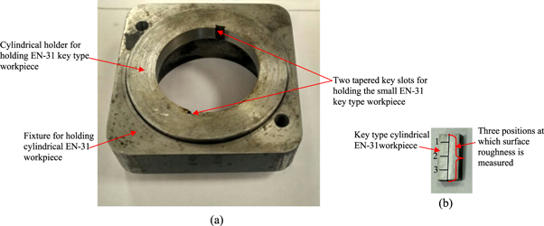
Figure 3. Photograph of (a) cylindrical ferromagnetic EN-31 steel workpiece having two key slots along with its fixture and (b) cylindrical key type EN-31 workpiece.
Download figure:
Standard image High-resolution imageThe cylindrical EN-31 holder along with its fixture as shown in figure 3(a) is further gripped by grinding precision vice clamped over the honeycomb breadboard as shown in figure 1. The initial ground surface of all key type workpieces is prepared by the internal cylindrical grinding process and measured using surface roughness tester named Mitutoyo SJ- 400. The initial and final measurement of surface roughness (i.e. before and after finishing) is performed at three different stages (1, 2 and 3) as shown in figure 3(b) over a straight line on the cylindrical key type EN-31 workpiece. The average of three measurements is calculated and taken as initial and final surface roughness value. The cut-off length for measuring the surface roughness is kept as 0.25 mm. Thoroughly mixed MR polishing fluid constituting of carbonyl iron (CI) particles, silicon carbide (SiC) abrasives, heavy paraffin oil and AP3 grease is used for experimentations.
The initial values of surface roughness are not same for all the workpieces that is why the percentage variation in surface roughness (%ΔRa) value is considered as the final response which is calculated by using the equation (1).

Response surface methodology (RSM) is made up of a collection of statistical and mathematical methods used for the advancement of a useful correlation between the inputs and the outputs. RSM determines the relation between the independently controlled variables and the final response. The experimental conditions decide the combinations of factor levels in the design. Five levels, central composite design with six central runs has been utilized to perform the experiments. 'F' test via analysis of variance (ANOVA) is performed in order to analyze the importance of regression equation in detailing the connections between the response outputs and the control variables. RSM has been utilized to monitor the effects of five process parameters on the percentage alteration in surface roughness value (% ΔRa).
The process parameters represented by its coded levels and along with its actual values used for finishing of the internal ferromagnetic surface of the EN-31 workpiece by using the developed MR honing tool are given in table 2. The carbonyl iron particles of 400 mesh size, silicon carbide (SiC) abrasives of 600 mesh size have been taken for the complete design of experimentations. Each set of finishing experiments has been performed for 40 min. The cylindrical ferromagnetic workpiece made up of EN-31 die steel material has been utilized for experimentations. The mixing chamber has been used for preparing the MR polishing fluid indigenously. The experimentation has been performed for finishing of the internal ferromagnetic surface according to the design of experiments as given in table 2.
Table 2. Actual values of process parameters along with its coded levels.
| Levels | |||||||
|---|---|---|---|---|---|---|---|
| Sr No. | Process parameter | Units | −2 | −1 | 0 | 1 | 2 |
| 1. | Percentage concentration of silicon carbide (SiC) abrasives (S) | % | 15 | 17.5 | 20 | 22.5 | 25 |
| 2. | Percentage concentration of carbonyl iron particles (C) | % | 15 | 17.5 | 20 | 22.5 | 25 |
| 3. | MR honing tool rotational speed (R) | rpm | 300 | 400 | 500 | 600 | 700 |
| 4. | MR honing tool reciprocational speed (Z) | cm min−1 | 50 | 60 | 70 | 80 | 90 |
| 5. | Working gap (W) | mm | 1.5 | 2.0 | 2.5 | 3.0 | 3.5 |
Table 3. Summary of responses.
| Factors | ||||||||
|---|---|---|---|---|---|---|---|---|
| Std order | (S) | (C) | (R) | (Z) | (W) | Initial Ra value (nm) | Final Ra value (nm) | Response (% ∆Ra) |
| 1 | 22.5 | 22.5 | 400 | 60 | 2 | 479 | 268 | 44 |
| 2 | 17.5 | 17.5 | 400 | 60 | 2 | 485 | 281 | 42 |
| 3 | 22.5 | 17.5 | 600 | 60 | 2 | 498 | 204 | 59 |
| 4 | 20 | 20 | 500 | 90 | 2.5 | 481 | 236 | 51 |
| 5 | 17.5 | 22.5 | 600 | 80 | 3 | 499 | 259 | 48 |
| 6 | 17.5 | 17.5 | 400 | 80 | 2 | 478 | 263 | 45 |
| 7 | 20 | 20 | 500 | 70 | 3.5 | 481 | 303 | 37 |
| 8 | 17.5 | 22.5 | 400 | 60 | 2 | 478 | 311 | 35 |
| 9 | 17.5 | 17.5 | 600 | 60 | 2 | 494 | 247 | 50 |
| 10 | 20 | 20 | 500 | 70 | 2.5 | 482 | 227 | 53 |
| 11 | 17.5 | 22.5 | 400 | 80 | 2 | 481 | 250 | 48 |
| 12 | 17.5 | 17.5 | 600 | 80 | 2 | 476 | 257 | 46 |
| 13 | 17.5 | 22.5 | 600 | 60 | 2 | 476 | 228 | 52 |
| 14 | 20 | 20 | 500 | 70 | 2.5 | 477 | 196 | 59 |
| 15 | 22.5 | 17.5 | 600 | 80 | 2 | 485 | 238 | 51 |
| 16 | 22.5 | 17.5 | 400 | 60 | 2 | 496 | 233 | 53 |
| 17 | 17.5 | 22.5 | 600 | 80 | 2 | 479 | 211 | 56 |
| 18 | 22.5 | 22.5 | 600 | 80 | 2 | 488 | 220 | 55 |
| 19 | 20 | 15 | 500 | 70 | 2.5 | 491 | 246 | 50 |
| 20 | 17.5 | 17.5 | 400 | 60 | 3 | 483 | 314 | 35 |
| 21 | 20 | 20 | 500 | 50 | 2.5 | 472 | 245 | 48 |
| 22 | 22.5 | 17.5 | 400 | 60 | 3 | 492 | 251 | 49 |
| 23 | 17.5 | 22.5 | 400 | 60 | 3 | 486 | 326 | 33 |
| 24 | 20 | 20 | 500 | 70 | 2.5 | 485 | 209 | 57 |
| 25 | 22.5 | 22.5 | 400 | 60 | 3 | 477 | 329 | 31 |
| 26 | 17.5 | 17.5 | 600 | 60 | 3 | 483 | 270 | 44 |
| 27 | 20 | 20 | 500 | 70 | 2.5 | 478 | 220 | 54 |
| 28 | 22.5 | 17.5 | 600 | 60 | 3 | 493 | 251 | 49 |
| 29 | 17.5 | 22.5 | 600 | 60 | 3 | 483 | 266 | 45 |
| 30 | 20 | 20 | 700 | 70 | 2.5 | 478 | 206 | 57 |
| 31 | 22.5 | 22.5 | 600 | 60 | 3 | 485 | 281 | 42 |
| 32 | 17.5 | 17.5 | 400 | 80 | 3 | 475 | 266 | 44 |
| 33 | 20 | 20 | 500 | 70 | 2.5 | 491 | 226 | 54 |
| 34 | 22.5 | 17.5 | 400 | 80 | 3 | 492 | 261 | 47 |
| 35 | 20 | 20 | 300 | 70 | 2.5 | 494 | 287 | 42 |
| 36 | 20 | 20 | 500 | 70 | 2.5 | 483 | 208 | 57 |
| 37 | 17.5 | 22.5 | 400 | 80 | 3 | 484 | 266 | 45 |
| 38 | 22.5 | 22.5 | 400 | 80 | 3 | 493 | 281 | 43 |
| 39 | 22.5 | 17.5 | 600 | 80 | 3 | 487 | 258 | 47 |
| 40 | 22.5 | 22.5 | 600 | 80 | 3 | 489 | 274 | 44 |
| 41 | 15 | 20 | 500 | 70 | 2.5 | 478 | 306 | 36 |
| 42 | 25 | 20 | 500 | 70 | 2.5 | 485 | 281 | 42 |
| 43 | 22.5 | 17.5 | 400 | 80 | 2 | 498 | 244 | 51 |
| 44 | 22.5 | 22.5 | 600 | 60 | 2 | 487 | 234 | 52 |
| 45 | 20 | 25 | 500 | 70 | 2.5 | 483 | 261 | 46 |
| 46 | 22.5 | 22.5 | 400 | 80 | 2 | 488 | 234 | 52 |
| 47 | 20 | 20 | 500 | 70 | 1.5 | 497 | 214 | 57 |
| 48 | 20 | 20 | 500 | 70 | 2.5 | 496 | 218 | 56 |
| 49 | 17.5 | 17.5 | 600 | 80 | 3 | 498 | 289 | 42 |
| 50 | 20 | 20 | 500 | 70 | 2.5 | 478 | 215 | 55 |
4. Response surface regression analysis
The responses in terms of percentage alteration in surface roughness (Ra) value (% ∆Ra) during each set of experimentation are reported in table 3. The responses in terms of % ∆Ra values have been analyzed using equation (1). The ANOVA for the entire model is given in table 4. At present, the significant level i.e. α = 0.05 has been taken for the given hypothesis for which p-value ≤0.05 is considered as significant. The terms such as S, C, R, Z, W, S2, C2, R2, Z2, W2, SC, SR, SZ, SW, CR, CZ and RZ are significant. If the p-value is >0.05 then the terms are considered as insignificant. If insignificant terms exist in the model, then the model can further be improved by eliminating the insignificant terms. The R2 value determines the closeness of experimental data points with the regression fit line. The R2 for the given model is 0.93. This means that the model determines a good response input.
Table 4. ANOVA for % ∆Ra value.
| Source | Sum of squares | Degree of freedom | Mean square | F-value | P-value | Remarks | Percentage contribution |
|---|---|---|---|---|---|---|---|
| Model | 2253.35 | 17 | 132.55 | 25.45 | < 0.0001 | significant | |
| S | 126.02 | 1 | 126.02 | 24.19 | < 0.0001 | 5.59 | |
| C | 34.22 | 1 | 34.22 | 6.57 | 0.0153 | 1.51 | |
| R | 330.62 | 1 | 330.62 | 63.48 | < 0.0001 | 14.67 | |
| Z | 75.62 | 1 | 75.62 | 14.52 | 0.0006 | 3.35 | |
| W | 511.22 | 1 | 511.22 | 98.16 | < 0.0001 | 22.68 | |
| S2 | 457.53 | 1 | 457.53 | 87.85 | < 0.0001 | 20.30 | |
| C2 | 75.03 | 1 | 75.03 | 14.40 | 0.0006 | 3.32 | |
| R2 | 42.78 | 1 | 42.78 | 8.21 | 0.0073 | 1.89 | |
| Z2 | 42.78 | 1 | 42.78 | 8.21 | 0.0073 | 1.89 | |
| W2 | 101.53 | 1 | 101.53 | 19.49 | 0.0001 | 4.50 | |
| SC | 101.53 | 1 | 101.53 | 19.49 | 0.0001 | 4.50 | |
| SR | 22.78 | 1 | 22.78 | 4.37 | 0.0445 | 1.01 | |
| SZ | 22.78 | 1 | 22.78 | 4.37 | 0.0445 | 1.01 | |
| SW | 22.78 | 1 | 22.78 | 4.37 | 0.0445 | 1.01 | |
| CR | 52.53 | 1 | 52.53 | 10.08 | 0.0033 | 2.33 | |
| CZ | 132.03 | 1 | 132.03 | 25.35 | < 0.0001 | 5.85 | |
| RZ | 101.53 | 1 | 101.53 | 19.49 | 0.0001 | 4.50 | |
| Residual | 166.65 | 32 | 5.20 | ||||
| Lack of Fit | 138.77 | 25 | 5.55 | 1.39 | 0.3418 | not significant | |
| Pure Error | 27.87 | 7 | 3.98 | 0.09 | |||
| Cor Total | 2420 | 49 |
The confidence interval of 95% low values and 95% high values are the lower and upper bound of 95% confidence interval that enclosed the coefficient approximate for the factor. The variance inflation factor (VIF) of the model quantifies how the variance is magnified by the need of orthogonality in the design. If the value of VIF is 1.00, then the factor is orthogonal to other factors within the model. If the value of VIF is >10, then the factors are not independent of each other. If the p-value is ˃ 0.05, then the model is regarded as not significant. The factor coefficient represents a span that the accurate coefficient must be initiated 95% of the time. The following equations (2) and (3) represents the quadratic equations which define the empirical relations between the process parameters. The final equation as per coded factors is represented in equation (2)

The final equation as per the actual factors is represented in equation (3).

The contributions of each process parameters on % ∆Ra value are given in table 4. The relation between the actual percentage alteration in surface roughness Ra value and predicted percentage alteration in surface roughness Ra value evaluated from the response surface regression analysis is shown in figure 4. From the figure 4, it can be observed that predicted value of percentage alteration in surface roughness parameter Ra are in close relation to the actual obtained experimental percentage alteration in surface roughness parameter Ra.
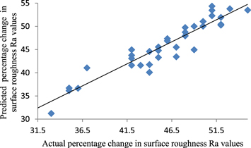
Figure 4. Graph showing the relation between the actual percentage change in surface roughness Ra value and predicted percentage alteration in surface roughness Ra value.
Download figure:
Standard image High-resolution image5. Results and discussion
The results are observed after the regression analysis of the responses. The effect of percentage concentration of the abrasive particles, percentage concentration of carbonyl iron particles, rotational speed of finishing tool, reciprocation speed of finishing tool and variation of working gap on the percentage alteration of roughness value (%ΔRa) of the surface have been observed and computed. The effects of these independent controllable variables on the % ΔRa value have been discussed as follows.
5.1. Effect of percentage concentration of silicon carbide abrasive particles
The concentration of silicon carbide abrasive particles present in the MR polishing fluid has a significant role in finishing the internal cylindrical surfaces while performing experimentation with the developed MR honing process. The sharp edges of abrasive particles erode out the material from the cylindrical workpiece's inner surface. When the abrasive particle's concentration is very less, then there remain insufficient numbers of abrasives to shear out the material. When the abrasive concentration is too high, the count of carbonyl iron (CI) particles chains becomes less to grip the increased number of abrasive particles and therefore superfluous abrasives are free to move. For a particular percentage concentration of CI particles, too low or high concentration of abrasives results in the less reduction in surface roughness value. There is a particular percentage concentration of abrasives for a particular concentration of carbonyl iron (CI) particles which makes most favourable MR polishing fluid. The effect of the concentration of SiC abrasives on the percentage alteration in the value of surface roughness (%∆Ra) at tool rotating speed of 500 RPM, tool reciprocating speed as 70 cm min−1, carbonyl iron particles concentration as 20% and a working gap of 2 mm is observed as shown in figure 5(a). For a particular percentage concentration of CI particles i.e. 20% in this case, when the SiC abrasive concentration is low i.e. below 20%, then it results with the low percentage alteration in the value of surface roughness (% ∆Ra). The reason behind this is that in these cases, not sufficient amount of abrasives are present in MR polishing fluid to erode the material. The rise in percentage concentration of SiC abrasives (up to 20%) boosts the percentage alteration in surface roughness values (% ∆Ra) due to the rise in a number of cutting edges of abrasives to erode out more material from the workpiece surface. But after certain limit i.e. 20% in present work, the increase in percentage concentration of abrasives results in a decrease in percentage alteration in surface roughness values (% ∆Ra). As in this case, there becomes so much number of SiC abrasives which can't be properly gripped by the CI particles chains. The SiC abrasives remain loose within the MR polishing fluid which rolls over the workpiece's surface and may even damage the surface while finishing. So it has been concluded from figure 5(a) that optimum percentage concentration of abrasives required for maximum material removal is 20% for a particular CIP concentration of 20%.

Figure 5. Effect of (a) percentage concentration of silicon carbide (SiC) abrasive particles, (b) percentage concentration of carbonyl iron (CI) particles, (c) MR honing tool rotational speed, (d) MR honing tool reciprocational speed and (e) working gap thickness on percentage change in surface roughness (Ra) value.
Download figure:
Standard image High-resolution image5.2. Effect of percentage concentration of carbonyl iron particles
The carbonyl iron particles present in the MR polishing fluid helps in gripping of abrasives by making chains. For a particular concentration of SiC abrasives in the MR polishing fluid, the rise in percentage concentration of carbonyl iron (CI) particles after certain limit leads to decrease in value of surface roughness. As the concentration of CI particles gets increased, the formed CI particles chains get denser which lead to the stronger gripping of abrasives over the surface of the workpiece. The effect of CI particles concentration present in the MR polishing fluid on percentage alteration in surface roughness value (∆Ra) with MR honing tool rotating speed of 500 RPM, tool reciprocating speed of 70 cm min−1, SiC particles concentration as 20% and a working gap of 2 mm is observed as shown in figure 5(b). It has been examined from figure 5(b) that for a particular percentage concentration of SiC abrasives i.e. 20% in this case, the percentage alteration in surface roughness values (% ∆Ra) gets increased with increase of CI particles concentration up to a level i.e. 20% in this case. After 20% increase in CI particles concentration, the percentage alteration in surface roughness value (% ∆Ra) starts decreasing. The reason behind this is that after 20% rise in CI particles concentration, the corresponding concentration of abrasives becomes less which is sufficiently required for the material removal in the present process [20]. Thus, it has been concluded that optimum percentage concentration of CI particles required for maximum material removal is 20% for a particular SiC concentration of 20%.
5.3. Effect of rotating speed of MR honing tool
The rotating speed of MR honing tool also plays a significant contribution in finishing the cylindrical workpiece's internal surface in the present MR honing process. The rotating speed of MR honing tool provides the tangential cutting force to the active abrasives which help in shearing out of roughness peaks from the cylindrical workpiece's internal surface. The effect of MR honing tool's rotating speed on percentage alteration in surface roughness value (% ∆Ra) at tool reciprocating speed of 70 cm min−1, SiC abrasive particles concentration as 20%, CI particles concentration as 20% and a working gap of 2 mm is observed as represented in figure 5(c). It is perceived from the figure 5(c) that at a low value of tool rotating speed i.e. 300 RPM, the percentage variation in surface roughness value (% ∆Ra) is low and it gets increased with the rise in tool's rotating speed. The percentage variation in surface roughness value (% ∆Ra) increase with the rise in MR honing tool's rotating speed up to 500 RPM. After 500 RPM speed of tool rotation, the percentage alteration in the value of surface roughness (% ∆Ra) starts decreasing. The reason behind this is that after 500 RPM speed of tool rotation, the bonding strength of MR polishing fluid does not remains sufficient enough to shear out the material from the cylindrical workpiece's inner surface. The centrifugal force (due to rotation of finishing tool) exerting over the CI particles weakens the magnetic normal force acting between the magnetic particles after 500 RPM of tool rotation. Therefore, at high tool rotating speed, the abrasives are not properly gripped by the CI particles chains and start rolling over the cylindrical workpiece's inner surface which results in less reduction in surface roughness values.
5.4. Effect of reciprocating speed of MR honing tool
The reciprocating speed of MR honing tool helps in eroding out of material from the workpiece surface by providing an axial force to the abrasives. The increase in reciprocating speed of MR honing tool leads to the rise in axial force acting over the abrasives to shear out the workpiece material. The effect of MR honing tool's reciprocating speed on percentage alteration in the value of surface roughness (% ∆Ra) at tool rotating speed of 500 RPM, SiC abrasive particles concentration as 20%, CI particles concentration as 20% and working gap of 2 mm is examined as represented in figure 5(d). It is observed from the figure 5(d) that at lower tool reciprocating speed of 50 cm min−1, the percentage variation in surface roughness is low. The percentage alteration in surface roughness value (% ∆Ra) increases with increasing reciprocating speed of MR honing tool and is maximum at 70 cm min−1. After further increasing the MR honing tool reciprocating speed beyond 70 cm min−1, the percentage alteration in surface roughness value (% ∆Ra) start decreasing. This is due to the reason that, after this limit i.e. 70 cm min−1, the SiC abrasive particles present over the workpiece surface become unstable due to the high axial force acting over the CI particles chains. At high reciprocating speed i.e. 80 cm min−1 or 90 cm min−1, the CI particles chains start breaking due to the high axial force acting over them and cannot grip the abrasives properly. So, the abrasives cannot perform the finishing properly and start rolling over the inner surface of the cylindrical workpiece. Due to this, the percentage variation in surface roughness value starts decreasing after MR honing tool reciprocating speed of 70 cm min−1.
5.5. Effect of working gap variation between the MR honing tool's outer surface and the inner surface of cylindrical workpiece
Working gap between the MR honing tool's outer surface and the inner surface of the cylindrical workpiece has a strong impact on the percentage alteration in surface roughness value (% ∆Ra). The effect of variation of working gap on percentage alteration in surface roughness value (% ∆Ra) at MR honing tool reciprocating speed of 70 cm min−1, tool rotating speed of 500 RPM, SiC abrasive particles concentration as 20% and CIPs concentration as 20% is observed as represented in figure 5(e). From the figure 5(e), it can be observed that on increasing the working gap from 2 mm to 3.5 mm, the percentage alteration in surface roughness value (% ∆Ra) gets decreased. The reason behind this is that magnitude of magnetic flux density within the working gap decreases with increase of working gap [21]. At higher working gap, magnetic force, Fi (which help CI particles to bind) acting between the two carbonyl iron (CI) particles gets decrease due to the decrease in intensity of magnetization as illustrated in equation (4) [22].

Here r represents the radius of carbonyl iron particle, R' represents the distance between the centers of two carbonyl iron particles and C represents the collect coefficient (a function of H). In this way, with the increased working gap, the bonding strength between the CI particles gets decreased and they cannot perform the proper finishing. Due to this, the percentage alteration in surface roughness (% ∆Ra) value decreases on increasing the working gap. When the working gap is 2 mm, there is an adequate magnetic flux density present within the working gap which is sufficiently required for the eroding of roughness peaks in the shape of microchips to result in the finished surface as shown in figure 6(a). When the working gap is 2 mm, initially, the abrasives slash out the peaks of roughness to make them flat. Then, with successive finishing cycles, abrasives erode out the all surface roughness peaks to result in the finished surface as shown in figure 6(a). For the working gap of 1.5 mm, the percentage alteration in surface roughness value (% ∆Ra) is less than that at working gap of 2 mm. This is due to the fact that for these particular parameters, high indentation force is applied by the abrasives of rigidly stiffened (equation (4)) MR polishing fluid onto the inner surface of cylindrical workpiece due to high magnetization within the working gap of 1.5 mm. Due to this high indentation force within the working gap of 1.5 mm, abrasives not only slash out the peaks but also strongly pluck out the material from its base surface as shown in figure 6(b). This generates the pit holes in the resulting finished surface and results in higher surface roughness value Ra. Due to this, for the working gap of 1.5 mm, percentage alteration in surface roughness value (% ∆Ra) is less than that at working gap of 2 mm.

Figure 6. Mechanism of material removal by MR honing tool with working gap thickness of (a) 2 mm and (b) 1.5 mm.
Download figure:
Standard image High-resolution image5.6. Effect of interaction of different concentration of SiC abrasives with different concentration of carbonyl iron particles
The effect of the interaction of different concentration of SiC abrasives with different concentration of carbonyl iron particles on percentage alteration in surface roughness Ra value at the reciprocating speed of 70 cm min−1, rotating speed of 500 RPM and a working gap of 2 mm is observed as shown in figure 7. For achieving significant surface finishing, the adequate concentration of SiC abrasive particles must be present in the MR polishing fluid with respect to the concentration of carbonyl iron (CI) particles. CI particles form chains to grip the abrasive particles. For a particular concentration of CI particles, if the percentage concentration of SiC abrasives is too low, then it would result in less variation in surface roughness value because of few numbers of available cutting edges. With the low concentration of abrasives, count of active abrasives present over the workpiece's surface remains less to perform adequate finishing. Also, for the same concentration of CI particles, if the percentage concentration of SiC abrasives is too high, then it would also result in less change in surface roughness value. As in this case, there are so many number of SiC abrasives which can't be properly held by the CI particles chains. The SiC abrasives remain loose in the MR polishing fluid which even damages the inner cylindrical surface while finishing. It can be observed from the figure 7 that maximum percentage alteration in surface roughness value is obtained with 20% concentration of CI particles and is adequate to grip the 20% concentration of SiC abrasive particles properly at tool rotation of 500 RPM, reciprocating speed of 70 cm min−1 and a working gap of 2 mm. The maximum surface roughness reduction is obtained with a combination of 20% concentration of CI particles and 20% concentration of SiC abrasives.
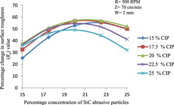
Figure 7. Effect of interaction of different concentration of silicon carbide abrasive particles with carbonyl iron particles concentrations on percentage change in surface roughness (Ra) value.
Download figure:
Standard image High-resolution image5.7. Effect of interaction of different rotating speed of MR honing tool with different concentration of silicon carbide abrasive particles
The effect of the interaction of different rotating speed of MR honing tool with different concentration of silicon carbide (SiC) abrasive particles on percentage alteration in Ra value at reciprocating speed of 70 cm min−1, CI particles concentration of 20% and working gap of 2 mm is presented in figure 8. It can be observed from the figure 8 that for a particular concentration of SiC abrasive particles, the rise in the tool rotating speed results in the increase in percentage alteration in surface roughness value. This is due to the increase in the magnitude of the tangential cutting force acting over the active abrasives as the rotating speed of the MR honing tool increases. But for a particular concentration of SiC abrasives, the increase in percentage variation in surface roughness value limits to a particular value of tool rotating speed which is 500 RPM for this particular observation. After 500 RPM speed of tool rotation, the percentage alteration in the value of surface roughness (% ∆Ra) starts decreasing. This is due to the fact that after 500 RPM speed of tool rotation, the bonding strength of MR polishing fluid does not remains sufficient enough to hold the abrasive particles and erode out the material from the workpiece's surface. The centrifugal force (due to rotation of MR honing tool) exerting over the CI particles weakens the magnetic normal force acting between the magnetic CI particles after 500 RPM of tool rotation. In the present observation, the further increase of SiC abrasive particles concentration beyond 20%, it becomes difficult for CI particles chains to properly grip the abrasive particles. Because of this reason, the percentage alteration in surface roughness Ravalue decreases for the higher percentage concentration of SiC abrasives i.e. 22.5% or 25%. The maximum percentage alteration in surface roughness Ravalue is obtained with a optimum combination of 20% concentration of SiC abrasive particles with 500 RPM rotating speed of MR honing tool.
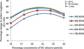
Figure 8. Effect of interaction of different rotational speed of MR honing tool with percentage concentration of silicon carbide abrasive particles on percentage change in surface roughness (Ra) value.
Download figure:
Standard image High-resolution image5.8. Effect of interaction of rotating speed of MR honing tool with working gap variation
The effect of interaction of different rotating speed of MR honing tool with the variation in working gap on percentage alteration in Ra value at 20% carbonyl iron (CI) particles concentration and 20% silicon carbide (SiC) abrasive particles concentration and 70 cm min−1 reciprocating speed of MR honing tool is observed as shown in figure 9. It can be observed from the figure 9 that for every value of rotating speed of MR honing tool, a higher value of working gap results in less percentage alteration in surface roughness Ra value. This is due to the proportionate decrease in magnetic flux density when working gap increases [21]. With the decreased magnitude of magnetic flux density within the increased working gap, the bonding strength of CI particles chains get decreased (equation (4)) due to which the CI particles chains cannot hold the abrasives tightly and subsequently cannot perform the adequate finishing action. This results in lesser percentage alteration in surface roughness Ra value. For a particular value of the working gap, the percentage alteration in surface roughness Ra value rise with increasing the rotating speed of the MR honing tool because of the rise in tangential cutting force exerted by the active abrasives. After the certain limit of rotating speed of MR honing tool i.e. 500 RPM in the present case, the percentage alteration in surface roughness Ra value starts decreasing because of the shear thinning effect of MR polishing fluid [21]. For the working gap of 1.5 mm in the present case, percentage alteration in surface roughness (Ra) value is lesser than that of the working gap of 2 mm. This is due to the high indentation force (due to high magnetization) exerted by the CI particles of the MR polishing fluid onto the inner surface of the cylindrical workpiece which creates small pit holes (figure 6(b)) and results in higher surface roughness Ra value. The maximum percentage alteration in surface roughness Ravalue is obtained with an optimum combination of working gap as 2 mm with 500 RPM rotating speed of MR honing tool.

Figure 9. Effect of interaction of different rotational speed of MR honing tool with working gap thickness on percentage change in surface roughness (Ra) value.
Download figure:
Standard image High-resolution image5.9. Effect of interaction of different concentration of silicon carbide abrasive particles with variation of working gap
The effect of interaction of different concentration of silicon carbide (SiC) abrasive particles with different working gap on percentage alteration in surface roughness Ra value with 20% carbonyl iron (CI) particles concentration, 500 RPM rotating speed of MR honing tool and 70 cm min−1 reciprocating speed of MR honing tool is observed as shown in figure 10. For individual working gap, the percentage alteration in surface roughness Ra value rises with increasing the percentage concentration of SiC abrasive particles due to the increase in count of cutting edges. After further increasing the concentration of SiC abrasives beyond a particular level i.e.20% for the present observation, result in lower percentage alteration in surface roughness Ra value. The reason behind this is that after 20% concentration of SiC abrasives, gripping of more number of abrasives by the same concentration of CI particles becomes difficult due to which abrasives rolls over the workpiece's surface. Percentage alteration in surface roughness Ravalue rises with a reduction in the working gap (figure 10) due to increased magnetization within the working gap. Percentage alteration in surface roughness Ra value for the working gap of 1.5 mm is slightly less as compared to the gap of 2 mm due to the formation of pit holes by the more rigidly (due to high magnetization) gripped abrasives as shown in figure 6(b). Therefore, the maximum percentage alteration in surface roughness Ravalue is obtained with an optimum combination of 20% concentration of SiC abrasive particles with working gap of 2 mm.
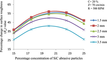
Figure 10. Effect of interaction of different concentration of silicon carbide abrasive particles with working gap thickness on percentage change in surface roughness (Ra) value.
Download figure:
Standard image High-resolution image5.10. Effect of interaction of different concentration of silicon carbide abrasive particles with reciprocating speed of MR honing tool
The effect of the interaction of different concentration of silicon carbide (SiC) abrasives with reciprocating speed of MR honing tool on percentage alteration in surface roughness Ra value with 20% carbonyl iron particle concentration, 500 RPM rotating speed of MR honing tool and a working gap of 2 mm is observed as shown in figure 11. With increasing the reciprocating speed of MR honing tool, axial force acting over the abrasives get increased due to which they erode out more material and results in increased percentage alteration in surface roughness Ra value. For a particular reciprocating speed of MR honing tool, the percentage alteration in surface roughness Ra value rises with the rise of abrasives percentage concentration up to 20% by volume as shown in figure 11. This is due to the increase in count of cutting edges with the rise in percentage concentration of SiC abrasives. But after a certain limit i.e. 20% in the present observation, the rise in percentage concentration of SiC abrasives leads to the lower percentage alteration in surface roughness Ra value. The reason behind this is the accumulation of more number of abrasives on the cylindrical workpiece's inner surface which cannot be properly held by the chains of CI particles. Freely dispersed abrasives roll over the cylindrical workpiece's inner surface and are unable to carry out the finishing. The percentage alteration in surface roughness Ra value increases with the reciprocating speed of MR honing tool but limit up to the speed of 70 cm min−1. After a further increase in reciprocating speed of MR honing tool, abrasives become unstable and cannot perform the adequate finishing. The maximum percentage alteration in surface roughness Ravalue is obtained with a combination of 20% concentration of SiC abrasive particles with 70 cm min−1 reciprocating speed of MR honing tool.
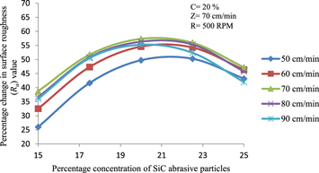
Figure 11. Effect of interaction of different concentration of silicon carbide abrasive particles with reciprocating speed of MR honing tool on percentage change in surface roughness (Ra) value.
Download figure:
Standard image High-resolution image6. Confirmatory experiments for validation of model
To confirm the regression model obtained in equation (3) with the experimental results in terms of % ∆Ra value, the five different experiments have been performed. The verification tests and their similarity with the predicted designed for % ∆Ra value is given in table 5. From this analysis, the percentage (%) error among the experimental and predicted data lies within range of −5.32% to 1.40%. The results found to be in good agreement with each other.
Table 5. Confirmatory experiments to validate the results obtained from the regression model.
| Process parameters | ||||||||
|---|---|---|---|---|---|---|---|---|
| Sr No. | S | C | W | R | Z | Experimental (% ∆Ra) value | Predicted (% ∆Ra) value | Error (%) |
| 1 | 17.5 | 15 | 2 | 600 | 50 | 43.20 | 45.50 | −5.32 |
| 2 | 15 | 20 | 2.5 | 600 | 70 | 37.11 | 40.05 | −7.92 |
| 3 | 22.5 | 22.5 | 2 | 700 | 50 | 49.57 | 51.09 | −3.06 |
| 4 | 20 | 22.5 | 2.5 | 300 | 70 | 38.83 | 39.92 | −2.80 |
| 5 | 17.5 | 20 | 3 | 500 | 80 | 46.97 | 46.31 | 1.40 |
7. Optimization of process parameters
As the least value (Ra) of surface roughness is required for the final finished surface therefore to attain the highest percentage alteration in Ra value, the optimization of quadratic model can be predicted from the results obtained. The optimum process parameters have been predicted on the basis of the effect of each process variable on % ∆Ravalue. Optimization of process parameters has been performed in Design Expert making use of Derringer and Suich (1980) algorithm [23] For each response Yi, a desirability function di (Yi) has been assigned ranging from 0 to 1. Here 0 means completely undesirable response and 1 represent completely required response or ideal response. The individual desirabilities are then merged to obtain the overall desirability function (D) which can be calculated by equation (5).

Here j represents the number of response variables. Design expert software find out the best optimum combination of parameters having the maximum value of desirability function (D) [24]. After analyzing, the optimum process parameters have been found as mentioned in table 6. Feasibility of optimum process parameters of MR honing process has been confirmed by performing the experimentations on the internal cylindrical surface workpiece of EN-31 (as similar to those used in plan of experiments) by using optimum process parameters (table 6). The initial surface roughness (Ra) value of EN-31 cylindrical workpiece was measured as 476 nm. The experimentation was performed for 120 min of finishing. The MR polishing fluid was renewed after 20 min of finishing on the outer surface of finishing tool for maintaining same quality of polishing fluid in each finishing cycle. Smallest value of surface roughness of 95 nm is achieved from the initial of 476 nm after 120 min of finishing. During the first two sets of finishing i.e. up to 40 min of finishing, value of surface roughness parameter Ra decreases very quickly as it can be observed in figure 12. This is due to shearing of surface roughness peaks having sharp peaks. Change in surface roughness Ra value gets decreased during the successive finishing cycles. As the finishing cycles proceed, the surface area of roughness peaks material gets increased due to which it goes on becoming difficult to shear out the flat peaks having more shear strength. After 120 min of finishing, roughness peaks become almost flat due to which least value of 95 nm of surface roughness parameter Ra is obtained. When one more set of 20 min finishing is performed, abrasives pluck out the material from the base surface due to which at some places, and cavity get formed. Due to these formed cavities, the surface roughness parameter Ra get increased to 110 nm from the 95 nm finished surface as it can be seen in figure 12. Percentage reduction in surface roughness parameter (% ∆Ra) obtained from both i.e. experimentally and the regression model with optimum process parameters has been represented in table 7. Percentage error between the two has also been evaluated as represented in table 7. Evaluated values as represented in table 7 signifies that predicted values of percentage change in surface roughness parameter (Ra) are in closer agreement with the experimentally obtained values. The profiles of surface roughness of initial ground and final surface after 120 min of finishing are represented in figures 13(a) and (b). Scanning electron microscopy (SEM) at 500X test has also been performed to inspect the performed finishing textures as shown in figures 14(a) and (b). From SEM images, the finishing surface textures by the present developed MR honing tool can be observed. It can be clearly observed from the SEM images that all the grinding marks and surface cavities over the cylindrical EN-31 workpiece surface have been removed to result the better finished surface textures during the finishing performed by the developed MR honing tool. The present developed magnetorheological (MR) honing process is useful for significant internal finishing of cylindrical workpieces made up of EN-31 die steel after the traditional finishing processes to improve its functional applications. The finished EN-31die steel can be used in aerospace, automobile and mechanical industry. It can be used for manufacturing various products like cylindrical components used for flow of high purity gases, dies and moulds for injection molding and hydraulic and pneumatic cylinders etc.
Table 6. Optimum process parameters.
| Parameters | Values |
|---|---|
| Percentage concentration of SiC abrasive particles (S) | 20% |
| Percentage concentration of of CIPs (C) | 20% |
| MR honing tool rotational speed (R) | 500 rpm |
| MR honing tool reciprocational speed (Z) | 70 cm min−1 |
| Working gap (W) | 2 mm |

Figure 12. Change in surface roughness (Ra) values with respect to finishing time with optimum process parameters.
Download figure:
Standard image High-resolution imageTable 7. Comparison of percentage change in surface roughness parameter (Ra) obtained from experimentation and regression model.
| Optimum process parameters | % ΔRa(From experimentation) | % ΔRa(From regression model) equation (3) | % Error |
|---|---|---|---|
| S = 20% | |||
| C = 20% | |||
| R = 500 rpm | 54.83 | 57.11 | −4.15 |
| Z = 70 cm min−1 | |||
| W = 2 mm |

Figure 13. Surface roughness profiles of (a) initial ground surface and (b) final finished surface after 120 min of finishing (at S = 20%, C = 20%, W = 2 mm, R = 500 RPM and Z = 70 cm min−1).
Download figure:
Standard image High-resolution image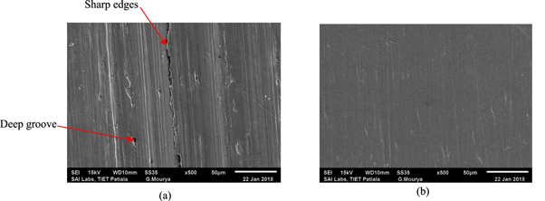
Figure 14. Scanning electron microscopy images at 500X of (a) initial ground surface and (b) final finished surface after 120 min of finishing (at S = 20%, C = 20%, R = 500 RPM, Z = 70 cm min−1 and W = 2 mm).
Download figure:
Standard image High-resolution image
8. Conclusions
In the current study, parametric optimization using statistical design of experiments of newly developed magnetorheological honing (MRH) process has been performed to identify the optimum process parameters for precisely finishing of EN-31 die steel. The following conclusions are obtained from the current study.
- Percentage change in surface roughness (Ra) value is majorly contributed by the working gap followed by the tool rotating speed, the percentage concentration of silicon carbide particles, the tool reciprocating speed and the percentage concentration of carbonyl iron particles.
- Finishing at different working gaps clearly demonstrated that the present developed process is having flexibility for nano-finishing of different cylindrical diameters with the same designed tool.
- The optimum process parameters to finish the internal surface of the ferromagnetic cylindrical EN-31 steel are found as 20% concentration of SiC abrasive particles, 20% concentration of carbonyl iron particles, the rotational speed of tool as 500 RPM, the reciprocation speed of tool as 70 cm min−1 and the working gap of 2 mm.
- The least surface roughness Ra value of 95 nm is achieved from the initial Ra value of 476 nm in 120 min of finishing with the optimized parametric conditions using the present developed MR honing process.
- Scanning electron microscopy (SEM) images illustrated that the developed magnetorheological honing process is capable to remove various surface defects like deep grooves and sharp edges from the internal cylindrical ground surface of EN-31 steel and resulted in defect free surface.
Acknowledgments
The authors deeply thankful to 'Science and Engineering Research Board' Department of Science and Technology, New Delhi, India (Project no.EMR/2015/000330) for giving a financial support.