

Abstract
Gravitational forces that oscillate at audio-band frequencies are measured with masses suspended as pendulums that have resonance frequencies even lower. If the pendulum is excited by thermal energy or by seismic motion of the environment, the measurement sensitivity is reduced. Conventionally, this problem is mitigated by seismic isolation, potentially combined with cryogenic cooling. Here, we propose mechanical parametric cooling of the pendulum motion, continuously even during the measurements. Different from linear damping, the actuator of our approach does not need a mechanically stable reference point. We report a proof of principle demonstration in the seismic noise dominated regime and achieve a damping factor of the pendulum motion of 5.7. We find a model system for which mechanical parametric feedback cooling reaches the quantum mechanical regime near the ground state. Gravitational-wave detectors would already be improved with much lower cooling factors.
Export citation and abstract BibTeX RIS
1. Introduction
Precision experiments on the gravitational field such as gravitational-wave detectors [1] or measurements of the gravitational constant [2] rely on complex pendulum-like suspensions to minimize non-gravitational coupling to movements in the environment [3]. The pendulum's resonance frequency needs to be smaller than the measurement frequencies, at which the pendulum mass is then quasi-free in the direction of pendulum motion. At their resonance frequencies, however, these pendulums are very susceptible to external disturbances. They excite their oscillatory modes, and due to their low mechanical losses the natural ring-down times are very long. This problem is conventionally mitigated using active linear feedback damping [4] or passive frictional damping [5]. With active linear feedback, sensor noise as well as actuator noise is translated into actuation force on the pendulum, adding broadband noise to the measurement. In the Advanced LIGO detectors for example, control noise dominates the sensitivity at frequencies between 10 Hz and 20 Hz [6]. On the other hand, passive frictional damping results in a stronger coupling to the thermal bath and the structure supporting the damping elements. Consequentially, with increasing friction, the thermally excited motion of the test mass at frequencies above resonance also increases [7].
An alternative that evades the drawbacks of both aforementioned damping schemes is parametric damping, which utilizes modulation of oscillation parameters instead of external forces or dissipation to realize the damping effect. With parametric damping, no force is applied in the sensitive horizontal direction but still the horizontal motion is damped. Also the actuation happens at the top of the pendulum suspension and not near the sensitive test mass. Parametric damping doesn't require a broadband control loop that potentially injects noise significantly above the resonances to be damped. Parametric couplings have proven a useful tool in various areas of research, including gravitational wave detection [8]. The center-of-mass motion of a laser-trapped nanoparticle was cooled from room temperature to ∼50 mK using parametric feedback on the laser intensity [9]. Using parametric gain or damping on an oscillator coupled to a microwave cavity poses an additional possibility for manipulating intracavity fields [10]. Furthermore, dispersive optomechanical cooling employs an optical cavity of which the resonance frequency is (parametrically) modulated by the position of the mechanical oscillator to be cooled [11–13]. Average mechanical mode occupation numbers below unity were achieved [14, 15]. In optics, nonlinear parametric processes enable the squeezing of power fluctuations below those of a displaced ground state (coherent state) [16, 17]. Parametric amplification was previously used in micro-electromechanical systems to overcome readout noise [18].
Here, we realize stably controlled parametric damping of a pendulum with resonance frequency ω0 = 2π · 1.3585 Hz by vertical actuation of the suspension point at frequency Ω = 2ω0 as illustrated in figure 1. We also find a model pendulum system which could provide the basis for macroscopic quantum-optomechanical experiments utilizing parametric cooling.

Figure 1. Schematic of the parametric cooling principle. If the suspension point executes a harmonic vertical motion at twice the pendulum angular resonance frequency  , with l the pendulum length and g the gravitational acceleration, with a phase as indicated by the path on the bottom, energy is removed from the pendulum oscillation.
Download figure:
Standard image High-resolution image2. Theory
2.1. Mechanical parametric cooling
Assume a pendulum with resonance frequency ω0, with a point-like mass suspended by a massless rod of length l subject to viscous damping and the suspension point executing a harmonic vertical motion  (figure 1). The equation of motion is given by [19]

where ϕ ≪ 1 is the deflection angle of the pendulum, γ is the natural damping rate, defined as the reciprocal of the 1/e energy damping time and g is the gravitational acceleration.  is the vertical acceleration of the suspension point with amplitude z0, which acts as a parametric drive. By performing the substitution
  , equation (1) is transformed to [20]:

where  . This is a form of the Mathieu equation [20]. In general, the Mathieu equation has the two independent solutions

with periodic functions p1, p2 and a real or purely imaginary characteristic exponent
μ [21]. In the case of a real μ, one of the solutions diverges exponentially. This phenomenon is called parametric resonance and it occurs around excitation frequencies Ω ≈ 2ω0/n with integer n [21]. Figure 2 shows the real part of the characteristic exponent versus drive frequency and amplitude. For a given small parametric amplitude z0 ≪ l, the effect is strongest for Ω = 2ω0. In this case, the functions p1, p2 can be approximated by  and
and  , respectively and the exponent μ is approximately μ ≈ 2ω0
z0/l [21]. This means an initial excitation that is in phase with
, respectively and the exponent μ is approximately μ ≈ 2ω0
z0/l [21]. This means an initial excitation that is in phase with  will be exponentially excited while an excitation in phase with
  will be damped. The novelty in our approach is the focus on the damped component. After observing the phase of the existing pendulum mode excitation, we control the phase of the parametric drive such that the pendulum oscillation is in phase with the damped component. This situation is depicted in figure 1. Since the phase of the pendulum oscillation changes due to external influences such as seismics, the phase of the parametric drive needs to be adjusted repeatedly during operation to maintain damping. This can be realized using a phase lock loop. To account for friction, one can simply reverse the substitution performed in equation (2) to see that the natural damping rate γ adds to the parametric damping rate μ to form a total damping rate δ = γ + μ.

Figure 2. Map of the real-valued characteristic exponent μ in equation (3) describing the exponentially rising amplitude of the parametrically driven pendulum resonance ω0 [22]. z0/l is the amplitude of the vertical drive normalised to the pendulum length. Ω/ω0 is the frequency of the drive normalized to the pendulum's resonance frequency. Damping, however, requires a periodically constant and specific differential phase between the drive and the pendulum oscillation. Damping is possible only for Ω = 2ω0/n, with n being an integer. For these frequencies, the maximal damping rates equal the respective characteristic exponent μ. For small amplitudes z0 ≪ l, the optimum damping rate is achieved for Ω = 2ω0—here indicated by the vertical white line—with μ = 2ω0 z0/l being proportional to z0.
Download figure:
Standard image High-resolution image2.2. Thermal noise reduction
Parametric damping is not only able to compensate transient excitations and seismic noise, but also allows for reducing the root mean square amplitude of the motion below the value of a thermalized state and therefore makes cooling of a single mode possible [9, 13]. In view of spectral force measurements, the effect of parametric damping has to be described in the frequency domain. The coupling to a thermal bath can be understood as a random thermal force Fth acting on the oscillator. It has an autocorrelation given by the fluctuation-dissipation-theorem [23, 24] as  , where m is the oscillator's effective mass, γ is it's natural damping rate, kB
is Boltzmann's constant and T is the temperature. The single-sided power spectral density of the displacement x of a purely thermally excited oscillator is then Sxx
(ω) = ∣χ(ω)∣2
SFF,th(ω), where χ is the transfer function of the oscillator and SFF,th = 4m
γ
kB
T is the single-sided power spectral density of the thermal force, which is the Fourier-transform of the autocorrelation function
, where m is the oscillator's effective mass, γ is it's natural damping rate, kB
is Boltzmann's constant and T is the temperature. The single-sided power spectral density of the displacement x of a purely thermally excited oscillator is then Sxx
(ω) = ∣χ(ω)∣2
SFF,th(ω), where χ is the transfer function of the oscillator and SFF,th = 4m
γ
kB
T is the single-sided power spectral density of the thermal force, which is the Fourier-transform of the autocorrelation function  . For a harmonic oscillator with the equation of motion
  this evaluates to

Parametric damping by driving at the frequency Ω = 2ω0 changes the oscillator's displacement spectral density in a way that it modifies the damping rate (γ → γ + μ), yielding

The damping rate in the numerator is not modified since it represents the fluctuating thermal force exciting the oscillator, which is not influenced by parametric damping. This aspect is key for the cooling capability of parametric damping as we explain below. Figure 3 displays the impact of parametric damping on the thermal noise power spectral density of the motion of a thermalized pendulum mode. Parametric damping (solid) reduces the on-resonance thermal noise spectral density without increasing the thermal noise above resonance. The latter is relevant in precision experiments on the gravitational field like interferometric gravitational wave detectors and can be reduced by combining parametric damping with pendula of lower natural damping. In contrast, passive damping always raises the natural damping rate (dashed) [25] and comes with an increase in off-resonance thermal noise, the only exception being when the dissipative element used for passive damping is connected to a thermal bath with lower temperature [26].

Figure 3. Simulated square-root of the single-sided thermal noise spectral density for a pendulum with a length of 1 m, a natural Q-factor of 100 and a mass of 100 kg at room temperature (gray). The lowest curve shows the same pendulum with parametric damping that increases the damping rate by a factor of 10. For comparison, the dashed curve shows the resulting spectral density if the same damping rate was achieved using additional frictional damping. In this case, the off-resonance thermal noise is increased, raising the noise floor for measurements at these frequencies.
Download figure:
Standard image High-resolution image2.3. Loop sensor and actuator noise
Often the residual motion of a mechanical system that is actively damped by linear feedback is not due to thermal noise, but due to noise originating from the feedback-loop sensor or actuator. Sensor noise comes with the sensor signal (error signal), is amplified as well by the (frequency-dependent) complex-valued feedback loop gain, and thus transferred to the mechanical degree of freedom to be damped even if the actual sensor signal is zero. Sensor and actuator noise are issues in linear feedback systems, especially in those for suspension control in gravitational wave detectors [27]. Parametric feedback damping has fundamental advantages. First, the sensor signal and the noise accompanying it are not linearly translated to the actuator output. Instead, it is used to generate the phase locked actuator signal at twice the resonance frequency. Second, the coupling of the actuator movement is proportional to the pendulum's deflection equation (1), which reduces the relevance of actuator noise when the pendulum is at rest. The drawback of parametric feedback damping is a disturbance at precisely twice the frequency of the mechanical oscillator. Fortunately, this disturbance is generally of low magnitude since it is off-resonant and orthogonal to the horizontal, critical degree of freedom. Furthermore, it is rather harmless for the spectrum of the oscillator's motion because it has an arbitrary narrow linewidth, which is limited by the bandwidth of the phase lock loop used to generate the actuator signal. Even if some non-linear effects lead to up-conversion of the oscillating actuation signal into the measurement band, the resulting features will have a similarly narrow linewidth. Since these features will be correlated with the known applied actuation, the effect can even be mitigated in post-processing.
2.4. Thought experiment: mechanical ground state cooling
Once a parametrically damped oscillator has reached a stationary state described by the power spectrum in equation (5) we can associate a reduced temperature Tr
based on the mean square position fluctuation  obtained by integrating its power spectral density. Using the equipartition theorem,
  , one finds [9]

In other words, parametric damping allows the cooling of an oscillator below the temperature of its thermal environment. To achieve significant temperature reduction relative to the environment, the natural damping rate γ must be small compared to the parametric damping rate μ. In practice however, the minimal reachable excitation of a parametrically damped oscillator will not just be limited by the parametric damping rate but by the measurement of the phase of oscillation, which is required for effective parametric feedback, and additional sources of excitation such as seismic noise.
The usual criterion for an oscillator for being in its quantum ground state is a mean phonon occupancy 〈n〉 below unity. Since 〈n〉ℏ ω0 = kB Tr we find the requirement for the parametrically induced damping rate to reach the quantum mechanical regime near the ground state

With that we find a model system that would fulfill this condition. We could imagine a pendulum with a resonance frequency of ω0 = 2π · 1 Hz placed in a dilution refrigerator at a temperature of 2 mK [28]. In that case the parametric damping rate needs to surpass the natural damping rate by a factor of about 4e7. If the parametric damping rate corresponds to a Q-factor Qpar = ω0/μ as low as 100, which is certainly within reach, following the experimental part of this paper, the natural Q-factor Qnat = ω0/γ needs to have a value around 4e9. Q-factors in this regime have already been measured on violin modes of pendulum suspensions in gravitational wave detectors [29] and pendulum mode Q-factors around 108 have been demonstrated in fused silica pendulum suspensions [30, 31]. With an optimized choice of materials and suspension geometry, Q-factors in the regime of 1010 might be realizable for pendulum modes as well [32].
3. Proof-of-principle experiment
Our setup featured a 13 cm long pendulum which consisted of a cubic test mass suspended by thin wires. The test mass design can be seen in figure 4(b). The pendulum assembly was under vacuum. To decouple the assembly from environmental vibrations, the supporting base plate was suspended by Sorbothane rubber feet inside the vacuum chamber.
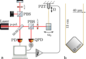
Figure 4. (a) Experimental setup. The pendulum oscillation at frequency f = 1.3585 Hz was parametrically cooled by vertical actuation of the suspension point at frequency 2f using a piezoelectric actuator (PZT). Motion of the pendulum test mass was measured in two ways. First, it was interferometrically read out using a photodiode (PD). Second, deflection of the reflected beam was measured using a quadrant photodiode (QPD) on a part of the reflected beam that was branched off using a polarizing beam splitter (PBS) and a quarter-wave-plate which is rotated in a way that the polarization of the reflected light is rotated only slightly and most of the light passes through the PBS. In the reference arm of the interferometer, a second PBS/quarter-wave-plate combination was used to balance the returning light power. The interferometer offered a higher resolution, but the signal was ambiguous, when the oscillation amplitude was greater than half of a wavelength. b Test mass front view. The cubic test mass hanged from a pair of tungsten suspension wires of 40 μm thickness. The left and right edges of the cube provided break-off points for the wires.
Download figure:
Standard image High-resolution imageThe vertical actuation of the suspension point was realized through a commercial piezoelectric actuator inside a flexure housing (Thorlabs APF503) with an actuation amplitude of up to z0 = 0.15 mm (z0/l ≈ 0.0011). The connection between the suspension and the test mass was made by two tungsten wire loops that were separated by a few millimeters. To minimize the bending losses in the wires, their diameter was chosen as small as possible without risking the wires breaking (40 μm in our case) [33].
The test mass was a milled aluminum cube with a side length of 33 mm and a mass of about 100 g (figure 4(b)). Two opposite sharp edges were aligned horizontally at the same height. This way, the edges provided well-defined break-off points for the wires. This is expected to minimize the friction of the wire at the contact area [34]. The two vertically oriented edges featured 45° chamfers of different depths for setting the center of mass slightly below the horizontally oriented edges. The front surface of the test mass was polished to serve as a mirror.
3.1. Optical sensing scheme
The main layout of the optical setup is shown in figure 4(a). The polished front surface of the pendulum mass reflected a coherent light field of 1550 nm wavelength. The reflected field was analyzed in two ways. First, a small part of the light returning from the test mass was branched off onto a quadrant segmented photodiode (QPD). This allowed the measurement of the beam deflection, which was caused by tilting of the test mass surface in the pendulum mode. The photocurrents of the upper half of the QPD were subtracted from the ones of the lower half. This delivered a signal that was roughly proportional to the pendulum's deflection. The phase of the pendulum mode was continuously reconstructed from the oscillating signal by recording segments of 5 seconds by the QPD in figure 4 and fitting a sine function to each segment. This phase in combination with the previously measured natural pendulum frequency were then used to adjust the parametric actuation feedback phase to achieve damping. The actuation signal continued with this phase until the next segment was recorded and analysed. Before reaching the actuator, the actuation signal was low-pass filtered to prevent sudden jumps in the signal when the phase was updated.
The amplitude was reconstructed using a Michelson interferometer configuration. With this, the phase modulation of the reflected field, caused by the back-and-forth motion of the test mass, was converted to an amplitude modulation. The intensity arriving at the output port was

where  is the mean intensity, V < 1 is the interference visibility, ϕ0 is a phase offset and xm
is the position of the test mass along the beam axis. This nonlinear and ambiguous relationship made it inadequate for phase and frequency reconstruction but gave the ability to measure the oscillation amplitude with more precision than the QPD. Figure 5 shows an example time trace of the two signals recorded by the quadrant photodiode and the interferometer. We utilized an algorithm that counted the number of interference fringes crossed per oscillation to reconstruct the amplitude. Since the pendulum always covered multiple interference fringes during each swing, this method provided sufficiently precise results in our proof-of-principle experiment.
is the mean intensity, V < 1 is the interference visibility, ϕ0 is a phase offset and xm
is the position of the test mass along the beam axis. This nonlinear and ambiguous relationship made it inadequate for phase and frequency reconstruction but gave the ability to measure the oscillation amplitude with more precision than the QPD. Figure 5 shows an example time trace of the two signals recorded by the quadrant photodiode and the interferometer. We utilized an algorithm that counted the number of interference fringes crossed per oscillation to reconstruct the amplitude. Since the pendulum always covered multiple interference fringes during each swing, this method provided sufficiently precise results in our proof-of-principle experiment.

Figure 5. Example time traces of the two sensor signals from the PD (fast oscillation) and the QPD in figure 4, used for measuring the pendulum motion. Shown is an interval of approximately one and a half oscillation periods of the pendulum. The oscillation amplitude was measured by counting the number of crossed interference fringes per oscillation period in the output power of the interferometer (PD, gray). The black trace shows the pendulum deflection measured by subtracting the photovoltages of the upper half and lower half of the quadrant segmented photodiode, calibrated using the interferometer output power signal. It was used to reconstruct the oscillation phase needed for parametric feedback. The additional high-frequency component visible on this trace is caused by the slightly excited pitch mode of the test mass.
Download figure:
Standard image High-resolution image3.2. Achieved damping performance
To measure the achievable parametric damping rate, we parametrically excited the pendulum with the maximal amplitude of our actuator of z0 = .15 mm. For this, the feedback phase was reversed. Subsequently, the ringdown of the pendulum amplitude was recorded with the parametric damping feedback enabled. Multiple measurements with varying feedback phases were taken until a value optimized for a maximal damping rate was found. For this optimal feedback phase, the measurement was repeated three times. Four measurements with only the natural damping after excitation served as the reference. Example measurements with and without parametric damping are shown in figure 6. Upon reaching an amplitude of approximately 10 μm, the QPD was no longer capable of determining the oscillation phase with sufficient precision and the parametric damping was switched off automatically.

Figure 6. Example ringdown measurements. The pendulum amplitude was recorded over time. In the beginning, the pendulum was parametrically excited, then the parametric damping feedback was either enabled (bottom curve) or left disabled (top curve). Shown here are two example curves from a total of 7 measurements. The slopes during the ringdown phases were used to reconstruct the parametric damping rate. The slopes were found by fitting linear functions (dashed). With parametric feedback enabled, the damping rate was the sum of parametric and natural damping rates (on average μ + γ = (17.9 ± 2.2)×−3 s−1), without it, it was solely the natural damping rate (on average γ = (3.12 ± 0.04) × 10−3 s−1). A larger actuation amplitude would have reduced the Q-factor further. This would have required a different actuator since we already utilized the maximum actuation range of ±0.15 mm.
Download figure:
Standard image High-resolution image
For each measurement, the overall damping rate was determined by fitting a linear function to the curve of the logarithm of the amplitude as seen in figure 6. The average natural Q-factor Qnat = ω0/γ of the pendulum was measured as 2740 ± 40. With parametric damping enabled, the Q-factor dropped to Qtot = 477 ± 6. This implies that the combined parametric and natural damping rates μ + γ exceeded the natural damping rate γ by a factor of 5.7. If the pendulum had no natural damping at all, the Q-factor would have been  enforced by the parametric damping rate alone as the Q-factors add with inverse law, 1/Qtot = 1/Qnat + 1/Qpar.
4. Discussion
For the actuation range z0 used in our setup, classical mechanics predicts a parametrically damped minimal Q-factor of  for an otherwise infinite-Q pendulum. The difference between this value and our experimental result of 580 can be attributed to non-perfect phase tracking of the feedback loop. In the regime of classical mechanics, the minimal Q-factor is independent of the initial pendulum amplitude. Our proof-of-principle experiment was performed at large amplitudes due to poor isolation from seismics. The lowest amplitude achieved, however, was not limited by continuous coupling to seismics but by the resolution of the tilt-measurement of the test mass. For oscillation amplitudes that are large compared to the sensing wavelength, alternative precise interferometric approaches with high dynamic range are available [35–37]. According to classical mechanics, the optimized phase difference between pendulum oscillation and actuation at twice the frequency does not depend on the oscillation amplitude. After optimization, the actuation is thus time-independent and may translate to a monochromatic feature in the measurement spectrum if the experiment is not ideal and shows some coupling. A single sharp line is often not an issue in spectrally analyzed data. In any case, phase and amplitude of actuation is known and can be efficiently subtracted from the data.
5. Conclusion
Vibration isolation systems and vibration mitigation of cryogenic cooling are limited in their performances. Therefore, high-Q-factor modes often need to be damped. In our proof-of-principle experiment, we increased the natural damping rate of a pendulum by a factor of 5.7 using mechanical parametric cooling. This method of damping the resonant excitation of the pendulum mode uses only vertical acceleration of the suspension point which heavily suppresses coupling of sensor and actuator noise to the horizontal test mass motion. Furthermore, unlike damping with linear feedback, parametric damping only creates a monochromatic disturbance in the measurement. These properties enable parametric damping to be used as a technology for reducing the control noise in gravitational wave detectors by combining it with conventional methods of control and alignment to reduce linear feedback gains and with them the coupling of sensor noise [6, 38]. We also realized a new test mass geometry for pendulum suspensions, which could also be interesting for gravitational wave detectors due to its simplicity.
Since parametric cooling does not increase the coupling to a thermal bath, it does not increase the thermal noise at any frequency, which is an advantage over frictional damping. If our pendulum was excited by thermal energy, the factor achieved corresponded to cooling of the pendulum mode from room temperature to about 50 K. Hypothetically, starting from a Q-factor of 4e9, a cryo-cooled 1 Hz pendulum at 2 mK could be cooled near its ground state if the pendulum is parametrically damped to a final Q-factor of 100.
Acknowledgments
This research has been supported by the European Research Council (ERC) project 'MassQ' (Grant No. 339 897) until 2019, and by the Deutsche Forschungsgemeinschaft (DFG, German Research Foundation) under Germany's Excellence Strategy EXC 2121 'Quantum Universe'390833306.
Data availability statement
The data that support the findings of this study are available upon reasonable request from the authors.
Conflict of interest
The authors have no conflicts to disclose.