
Abstact
Embedding piezoelectric materials as actuators or sensors into structures to form intelligent piezoelectric structures is a research hotspot. Piezoelectric intelligent structures should not only have good sensing and actuation performance, but should also ensure mechanical performance. The influence of forming and cutting embeddings of macro fiber composites (MFC) on the flexural and actuation properties of a piezoelectric composite curved shell was studied by simulation and experiment. The flexural performance was evaluated using a three-point bending simulation and test, and the actuation performance was evaluated by simulating the actuation deformation of a curved piezoelectric cantilever beam. Compared with forming embedding, cutting embedding destroys the continuity of the fiber, resulting in a reduction in the strength of the structure. However, it exhibits good actuation performance. Simultaneously, the influence of ply direction on performance was studied.
Export citation and abstract BibTeX RIS
1. Introduction
Piezoelectric materials can use piezoelectric effects to realize the mutual conversion of mechanical energy and electrical energy, so they are often used as sensors and actuators [1]. Piezoelectric intelligent structure is one of the research hotspots at present, and has made certain applications in the field of aerospace [2–4]. There are mainly two ways to integrate piezoelectric materials into structures, namely, pasting and embedding. The pasted piezoelectric intelligent structure is easy to fall off, damage, and be corroded by the external environment, but the embedded piezoelectric intelligent structure can effectively avoid these problems. In addition, Masmoudi and Abderrahim [5–7] used acoustic emission technology to monitor the state of surface bonding and internal embedded PZT sensors. The results show that the embedded sensors have higher sensitivity than surface sensors.
Considering that embedded piezoelectric structures may affect the structural integrity of matrix materials, many scholars have carried out relevant research on the mechanical properties of piezoelectric structures. Some studies show that the embedded piezoelectric material has a significant impact on the integrity of the matrix structure and then reduces the mechanical properties of the structure. Crawley et al [8] conducted static tensile tests on glass/epoxy composites embedded with piezoelectric materials. Lampani et al [9] studied the effect of different embedding positions on the overall mechanical properties of the structure by taking the laminates embedded with PZT at different positions in the matrix material as the object. Another study by Warkentin and Crawley [10] shows that the reduction of main structural integrity is largely caused by the discontinuity of laminate materials caused by embedded piezoelectric materials. Other studies show that a reasonable embedded design will not affect the mechanical properties of the structure. James et al [11] studied the effects of cutting ply embedding and forming embedding on the bending of piezoelectric structures through three-point bending and four-point bending tests. Later, James et al [12] found that the stress and strain borne by the embedded piezoelectric material were significantly greater than the recommended operating limit of its piezoelectric ceramic composition. Mall [13] studied the integrity of the main graphite/epoxy laminate embedded in piezoelectric ceramics (PZT) under monotonic and fatigue loads. Mall and Coleman [14, 15] embedded PZT into different cutting areas of the middle layer of isotropic graphite/epoxy laminates. David and colleagues [16] investigated the interlaminar stress state of a unidirectional graphite/epoxy laminate embedded with an active piezoelectric ceramic actuator.
In the study of dynamic performance, Crawley et al [17] integrated the bending static model of surface-bonded actuators and embedded actuators into the dynamic model of the cantilever Bernoulli Euler beam and deduced the point force model. Then, based on the assumption that the shear strain is linearly distributed along with the thickness, they studied the bonded piezoelectric beam and embedded piezoelectric beam. Vel et al [18] studied the analytical method of static deformation of a simply supported hybrid cylindrical shell composed of an embedded piezoelectric layer under the action of a radial electric field. Balamurugan and Narayanan [19, 20] studied the static and vibration behavior of composite piezoelectric plates or shell structures by using shell elements and found that embedding a piezoelectric layer can effectively control random vibration. Javdanitehran et al [21] embedded a printed circuit board sensor in a glass fiber reinforced polymer and carried out tensile and bending mechanical experiments according to the different included angles caused by different dimensions and different ply directions. Bruch [22] optimized the shape of the beam by many factors according to the influence of the position, size, and voltage of the piezoelectric actuator in the beam. Chung et al [23] introduced the PI hysteresis operator and the creep operator into the constitutive equation and proposed a nonlinear finite element model with hysteresis and creep characteristics by using the energy method and the Hamilton principle. Wang et al [24] applied the classical lamination theory to construct the laminated plate model embedded with a finite length piezoelectric actuator and used the orthogonal laminated plate embedded with a piezoelectric sheet to study the coupling of bending and extension. Senthil et al [25] used an analytical method and Eshelby Stroh form to study the bending deformation of a rectangular plate containing a piezoelectric sheet. Heyliger [26] gave an exact solution to the static behavior of laminated piezoelectric plates with simple supports. Under the assumption of linear elasticity and plane strain deformation, Yang et al [27] used mixed edge conditions to simulate simple supports and studied the forced vibration of cylindrically bending, simply supported plates with piezoelectric layers on the upper and lower surfaces by the Fourier series method. Chandra et al [28] took composite beams as the research object and analyzed the warpage and transverse shear deformation of piezoelectric beams in two different forms of surface-bonded and embedded piezoelectric actuators. Im et al [29] assumed that the beams had different displacements along the thickness of the laminate and established a piezoelectric laminated beam model considering the transverse shear deformation. To study the driving performance of MFC, Akash et al [30] developed Kirchhoff plate theory based on a two-dimensional model, incorporated it into the finite element formula, and carried out convergence research and stress analysis. Arnaud et al [31] used the finite element periodic homogenization method to evaluate the uniformity of the macro fiber composite (MFC) active layer. The proposed method was applied to d31 and d33 MFC at the same time, and the results showed good consistency. Based on the mixed multi-field variational formula, Schulz et al [32] proposed an electromechanical coupling shell element considering geometric and material nonlinearity. Bowen et al [33] established and verified a finite element model of asymmetric bistable laminates driven by piezoelectric macro-fiber composites.
This paper mainly studies the influence of two embedding methods on the bending performance and actuation performance of piezoelectric structures. The embedded piezoelectric element is MFC, and the matrix material is carbon fiber reinforced resin matrix composite (CFRP). The bending performance is completed by the three-point bending simulation and test, and the actuation performance is realized by the simulation of the actuation deformation of the piezoelectric cantilever curved beam.
2. Embedded piezoelectric curved shell
2.1. MFC
MFC is a kind of piezoelectric fiber sheet with excellent performance, and its essence is a composite material. When MFC modeling, it is often established for the core actuation area without considering its non-actuation area. For the surface-bonded piezoelectric intelligent structure, the influence of the non-actuating region can be ignored in the establishment of the MFC piezoelectric simulation model. The way can simplify the model and increase the calculation efficiency. However, embedded structure needs to consider the influence of the non-actuating area. This paper mainly studies the P1 type MFC. In the process of research, MFC is divided into five layers according to literature [34], as shown in figure 1, namely the kapton layer, the electrode layer, the actuator layer, the electrode layer, and the kapton layer. The thickness of each layer is 0.04 mm, 0.018 mm, 0.18 mm, 0.018 mm, and 0.04 mm, respectively.
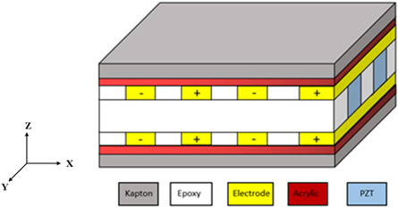
Figure 1. Structure diagram of P1 MFC.
Download figure:
Standard image High-resolution imageThe MFC-d33 type applies an inverse voltage on the adjacent electrodes of the same layer and the same voltage on the symmetrical interdigital electrode layer, so that a relatively evenly distributed electric field load is generated in the fiber direction of the active layer, and the distance between the adjacent electrodes is 0.5 mm. In this paper, the equivalent parameter modeling method is used to establish the model of the MFC actuation region, and the model parameters refer to [34].
2.2. Embedding method
There are two embedding methods of MFC, namely forming embedding and cutting embedding, as shown in figure 2. In order to obtain an accurate finite element model, the sections of two kinds of piezoelectric curved shells can be observed through an optical microscope, and the size parameters of the finite element model can be determined through analysis. According to the observation, the end wrinkling area in forming embedding is more obvious than that in cutting embedding mode. The profile under two embedding modes is obtained by fitting.
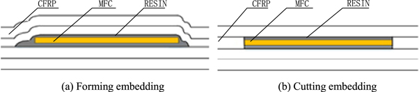
Figure 2. Sectional view of two embedding methods.
Download figure:
Standard image High-resolution image2.3. The specimen
The specimen is prepared by the vacuum assisted resin infusion process (VARI). Because MFC is embedded in the composite curved shell, its preparation process is more complex. The preparation diagram is shown in figure 3.

Figure 3. Schematic diagram of the embedded piezoelectric structure prepared by VARI.
Download figure:
Standard image High-resolution imageThe specimen preparation process is as follows:
- (1)Layering. In order to facilitate the release, the release agent should be repeatedly smeared on the bending shell mold before layering. In order to ensure a better release effect, it is necessary to apply the release agent twice, once to volatilize the release agent and then once to apply the release agent, and then the layering starts after the release agent volatilizes again. In view of the complex and variable layering angles of composite laminates, which have a significant impact on the overall performance of the structure, only orthogonal layering is considered in this paper, that is, only 0° and 90°. Since the thickness of the MFC is close to that of the single fiber layer, a single layer of fiber cloth can be cut when the cutting embedding method is used. At the same time, it is necessary to arrange the MFC wires reasonably to avoid the influence of excessive embedding of wires on the mechanical properties of the piezoelectric curved shell.
- (2)Vacuum bag package. After the laying of the carbon fiber cloth is completed, a flexible vacuum bag is used to package the carbon fiber cloth, and a layer of demoulding cloth is placed on the top carbon fiber cloth to separate the laminate from the mold after forming. According to the requirements of the parts, size, and shape to determine the resin flow into the channel and out of the channel. The resin flow was guided by the flow guide network, which was divided into two sections when laying the flow guide network. The resin flowed slowly in the middle section without the flow guide network, so that the resin was fully infiltrated into the carbon fiber cloth.
- (3)Resin configuration. According to the size and thickness of the parts, the required amount of resin is calculated. The epoxy resin glue and curing agent are prepared according to the ratio of 10:3, and the glass rod is used to stir until the mixture is evenly mixed. The bubbles in the mixture are removed by a vacuum pumping press, lasting for 45 min.
- (4)Resin injection. When the vacuum degree of the pressure gauge on the vacuum pumping machine reaches above 0.95 MPa, turn off the vacuum pumping machine. Check that the pressure gauge remains unchanged after 15 min before resin suction. When the other end of the rubber mouth overflows resin, the vacuum tube of the rubber mouth of the first layer of vacuum bag is clamped with a clip, so that the resin in the second layer of vacuum bag pressure under the action of 15 min continues pumping, the air bubbles in the plate from the rubber mouth.
- (5)Heat curing. The mold was put into the oven for heating and curing, and the oven temperature was set to 80 °C for 16 h. During the heating and curing process, the working state of the air drying oven was checked regularly to ensure the normal curing process.
- (6)Demoulding. After the setting time of the oven is over, turn off the power supply and wait for the temperature in the oven to drop below 40 °C. Open the chamber and take out the mold for demolding. The piezoelectric curved shell obtained by demoulding is shown in in figure 4.
- (7)Composite laminates cutting. High pressure water cutting quality is stable, high efficiency, and mechanical cutting not only incision chip accumulation phenomenon, and fiber and resin matrix interface will be destroyed. Considering the above factors and the existing conditions of the laboratory, this test decided to adopt the high-pressure water cutting method.
3. Simulation of bending properties of piezoelectric curved shell
3.1. Three-point bending model
Unconstrained support was used in the bending performance test. The indenter made the specimen reach the failure state or the predetermined deflection value at a constant loading speed, and then the applied force and the deflection at the corresponding time were obtained. Referring to ASTM D7264, the specimen for the three-point bending test is designed, and the span thickness ratio is set to 32:1. T700/5015 is selected for CFRP. The models are divided into two types, that is, forming embedding and cutting embedding. The finite element models for the three-point bending test are established respectively. The model of the three-point bending test is shown in figure 5. The CFRP layer is designed to be six layers. The layers are [0/90/0]2, [0/90]3, [0]6 and [90]6. The thickness of the specimen is related to the embedding method. The thickness of the non-embedded MFC is 1.5 mm, the thickness of the forming embedding is 1.7 mm, and the thickness of the cutting embedding is 1.6 mm. In order to obtain better test results, the standard MFC with model M2503-P1 is selected as the embedded element to complete the three-point bending test of the embedded piezoelectric structure. The detailed geometric parameters are shown in table 1.
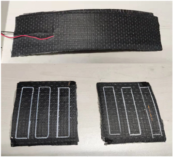
Figure 4. The specimen.
Download figure:
Standard image High-resolution image
Figure 5. Model of three-point bending test.
Download figure:
Standard image High-resolution imageTable 1. Geometric parameters of the three-point bending specimen.
| Shell radius/mm | Span/mm | Width/mm | Thickness/mm | Punch and supports radius/mm | Dimensions of MFC/mm3 |
|---|---|---|---|---|---|
| 1.5 | |||||
| 450 | 48 | 13 | 1.6 | 5 | 45 × 10 × 0.3 |
| 1.7 |
3.2. Mechanical property parameters
Combined with relevant papers, manufacturers and some experiments, the mechanical parameters of relevant materials are obtained as shown in table 2.
Table 2. Mechanical property parameters.
| Material | Property | Value |
|---|---|---|
| tensile modulus |

| |
| shear modulus |

| |
| Poisson's ratio |

| |
| T700/5015 | tensile strength |

|
| compressive strength |

| |
| shear strength |

| |
| density | ρ = 1.59 × 10⁻⁹ T mm−3 | |
| Epoxy resin | modulus |

|
| Poisson's ratio |

| |
| density | ρ = 1.2 × 10⁻⁹ T mm−3 | |
| MFC Actuation area | tensile modulus |

|
| shear modulus |

| |
| Poisson's ratio |

| |
| density | ρ = 5.44 × 10⁻⁹ T mm−3 | |
| MFC Non actuation area (Kapton) | modulus |

|
| Poisson's ratio |

| |
| density | ρ = 1.42 × 10⁻⁹ T mm−3 | |
| Cohesive | initial stiffness of interface |
 106 N mm−1 106 N mm−1
|
| interface peak strength | σmax,I = 50 MPa, σmax,II = 88 MPa, σmax,III = 88 MPa | |
| interlaminar fracture toughness | GI = 0.55 kJ mm−2, GII = 0.65 kJ mm−2, GIII = 0.65 kJ mm−2 | |
| density | ρ = 1.4 × 10⁻⁹ T mm−3 |
3.3. Meshing
For carbon fiber reinforced composites, the element control of the grid adopts a sweep mode. At the same time, it should ensure that the scanning direction is consistent with the stacking direction of the material attribute setting, that is, it should be the thickness direction, and the element is set as SC8R. For the non-actuating area and resin aggregation area of piezoelectric materials, the structure unit control mode is adopted, and the unit is set as C3D8R. For the actuating area of piezoelectric materials, the sweep unit control mode is adopted. At the same time, it is also necessary to ensure that the scanning direction is consistent with the stacking direction set by the material properties, that is, they are all in the thickness direction, and the unit is set as C3D8E.
Theoretically, the smaller the mesh of the finite element model is divided, the higher the calculation accuracy is. However, when the model is large, as the grid size becomes smaller and the grid density becomes larger, the amount of calculation of the model will increase significantly, so the calculation time will. At the same time, local grid refinement is carried out for the areas with complex stress changes, such as the resin aggregation area. In the model, the single-layer thickness direction of the composite is set as a fixed grid, that is, the grid size is 0.25. The thickness of the actuating region and non-actuating region in the thickness direction of the piezoelectric material is set as a three-layer grid. The size of the grid in the length and width directions needs to be carefully considered.
In this paper, the convergence criterion is used to plan the grid size reasonably, and the influence on the simulation results when the grid size decreases and the number of elements increases is considered. In order to avoid stress singularity, stress is not used as the judgment target of convergence, but the maximum displacement at the end is used as the judgment target. In the simulation process, the size of the grid is gradually reduced and the number of elements is increased from 1056 to 312620. It can be seen from figure 6 that when the grid size is less than 1 mm, the calculation accuracy is significantly improved. However, the improvement is no longer obvious as the size decreases, and the calculation time increases sharply, so the final grid size is 1 mm.
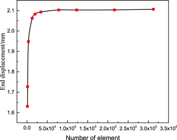
Figure 6. End displacement variation curve as the number of elements increases.
Download figure:
Standard image High-resolution image3.4. Simulation results
The three-point bending of curved beam without embedded MFC, cutting embedding curved beam and forming embedding curved beam are simulated by finite element method, respectively. The results of the force varying with displacement are shown in figure 7. It can be seen that under the two ply angles, the force of the punch is the largest under the conditions of forming embedding, and the force is small and close under the conditions of non-embedded MFC and cutting embedding.

Figure 7. Force displacement curve of simulation results.
Download figure:
Standard image High-resolution imageThe bending performance of the model is analyzed, and the maximum stress appears in the middle of the convex surface. The calculation formula for bending strength is as follows:

In the formula,  is the stress on the outer surface of the midpoint of the span, MPa; P is the force, N; l is the span, mm; b and h are the width and thickness, mm.
The results calculated by the formula (1) are shown in table 3. It can be seen that both embedding methods have influence on the bending strength of the piezoelectric curved shell.
Table 3. Strength under different embedding methods/MPa.
| Ply angle | Cutting embedding | Forming embedding | Non embedding |
|---|---|---|---|
| [0/90/0]2 | 452.30 | 521.27 | 474.83 |
| [0/90]3 | 414.28 | 514.55 | 428.38 |
| [0]6 | 609.65 | 725.52 | 545.99 |
| [90]6 | 199.12 | 256.71 | 201.48 |
In order to further explore the influence of the two embedding methods on the bending performance of the structure, the changes in the bending strength of the two embedding methods under different layers are analyzed, as shown in table 4. The results show that the bending strength caused by embedding MFC will also change with the ply direction, but the forming embedding always has better results. The forming embedding of MFC will cause resin aggregation in the surrounding area, and local fiber ply will wrinkle. The cutting embedding will destroy the continuity of the fiber and reduce its bending strength.
Table 4. Bending strength change ratio under different ply conditions.
| Ply angle | Cutting embedding mode | Forming embedding mode |
|---|---|---|
| [0/90/0]2 | −4.7% | +10.3% |
| [0/90]3 | −3.3% | +20.1% |
| [0]6 | +11.7% | +32.9% |
| [90]6 | −1.2% | +27.4% |
4. Test of bending properties of piezoelectric curved shells
The three-point bending test is completed on the ETM series electronic universal testing machine. The three-point bending loading device is shown in figure 8. The punch speed is set to 1 mm min−1.

Figure 8. Three-point bending loading device.
Download figure:
Standard image High-resolution imageThe experimental results are shown in table 5. The reduction of the bending strength of the structure caused by the introduction of piezoelectric elements under different ply angles is obtained, as shown in table 6 below. It can be seen that the bending strength of the curved shell decreases after embedding MFC, and the strength decreases more obviously due to the destruction of the continuity of the fiber by cutting the ply. The bending strength decreases by 9.81%, while the bending strength of the formed embedding method increases by 2.79% due to the non-destruction of the continuity of the fiber.
Table 5. Flexural performance test results.
| Flexural strength/MPa | |||
|---|---|---|---|
| Embedding mode | Non embedding | Cutting embedding | Forming embedding |
| [0/90/0]2 | 528.16 | 476.36 | 540.92 |
Table 6. Change value of embedded MFC on bending strength.
| Change value of bending strength (%) | ||
|---|---|---|
| Ply angle | Cutting embedding | Forming embedding |
| [0/90/0]2 | −9.81% | +2.79% |
Both results show that cutting embedding will reduce the flexural strength of the piezoelectric curved shell, but it is still in an acceptable range, and the bending strength changes little after forming embedded in MFC. Considering the obvious reduction in flexural performance caused by the way of cutting embedding, it is helpful to actuate the flexural deformation of the structure. The error between the experimental results and the simulation results is within the acceptable range, which shows that the finite element simulation results can reflect the real situation of the experiment, so the finite element model can be used for further research.
5. Study on the actuation performance of piezoelectric curved shell
5.1. Piezoelectric cantilever model
The actuation model is set as a cantilever curved shell, and the M8557-P1 MFC is embedded as an actuator. When building the model, MFC is also divided into cutting embedding and forming embedding, and the actuation performance is compared in the end. The cantilever curved shell model is shown in figure 9, and its geometric parameters are shown in table 7, where the radius of the middle surface of the column shell is R, the thickness is t, the width is w, and the length is L. The distance between the embedded MFC position and the cantilever end is L1.
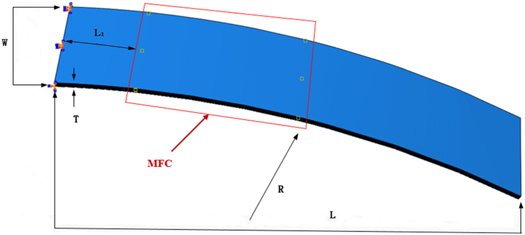
Figure 9. Piezoelectric cantilever model.
Download figure:
Standard image High-resolution imageTable 7. The geometric parameter of piezoelectric curved shell.
| R/mm | T/mm | W/mm | L/mm | L1 /mm | MFC |
|---|---|---|---|---|---|
| 450 | 1.5 | 64 | 305 | 50 | M8557-P1 |
CFRP also adopts the ply angles of [0/90/0]2 and [0/90]3, and the thickness of a single layer is 0.25 mm. MFC is embedded in the second layer. The piezoelectric performance parameters of MFC are shown in table 8.
Table 8. Piezoelectric property parameters in the MFC actuation area.
| Performance | Value | Performance | Value |
|---|---|---|---|
| d11 |

| Dielectric coefficient |

|
| d12 |

| Electrode spacing |

|
| Voltage range | −500 ∼ 1500V | Thickness |

|
5.2. Boundary conditions and loads
The piezoelectric curved shell is arranged as a cantilever curved shell structure. The voltage is applied to the MFC. Considering that the electrode inside MFC-d33 is a flexible interdigital electrode and the direction of the electric field is consistent with the direction of fiber actuation, the voltage is applied by equivalent voltage. The voltage applied to end face A is 0 ∼ 1500 V, and the voltage applied to end face B is 0 V. The relationship between equivalent voltage and applied voltage is as follows:

In the formula,  is the applied voltage;
  is the effective actuation length; and
  is the distance between adjacent electrodes.
5.3. Simulation results
Figure 10 shows the strain distribution, displacement response and MFC stress distribution of cantilever curved piezoelectric shell under different embedding modes at 1000V voltage. When a voltage is applied to the MFC, the deformation of the MFC will cause the deformation of the structure. Due to the action of the resin aggregation area, the normal stress of the MFC actuating end face is weakened and the shear stress becomes the dominant stress. The normal stress caused by the end face of MFC will directly act on the cut fiber layer, causing the fiber layers on both sides of MFC to produce strain, and greater deformation can be obtained under the action of shear stress. When MFC is embedded in cutting mode, the cutting layer is subject to compression deformation under the action of the MFC, and shear deformation occurs between layers, as shown in figures 10(a) and (b). In contrast, in the way of forming embedding, the large strain is concentrated near the action area of the MFC. As shown in figures 10(c) and (d), the piezoelectric curved shell obtains greater deformation by cutting embedding.

Figure 10. Strain and displacement nephogram of piezoelectric cantilever curved shell. (a) Forming embedding structure strain. (b) Cutting embedding structure strain. (c) Forming embedding structure displacement. (d) Cutting ply embedding structure displacement.
Download figure:
Standard image High-resolution imageFigure 11 shows the displacement response of the end intermediate node of the structure with the increase of applied voltage under different MFC embedding modes. The results show that the curved shell of MFC by forming embedding has better displacement response under the same voltage, and the difference in end displacement response gradually increases with the increase of voltage.
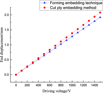
Figure 11. MFC displacement response curve.
Download figure:
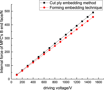
Standard image High-resolution imageFigure 12 shows the change curve of the MFC end face actuation force of the end intermediate node of the structure under different embedding modes with the increase of applied voltage. The results show that the cutting embedding has greater end face actuation force than the forming embedding. Similarly, the difference of actuation force gradually increases with the increase of voltage.
Figure 12. MFC dynamic force response curve.
Download figure:
Standard image High-resolution image
6. Conclusion
The embedded will affect the original mechanical properties of the structure. In order to ensure the flexural performance of the embedded structure, the effects of different embedding methods and layers of the piezoelectric curved shell embedded in MFC on the flexural strength are studied. In order to analyze the actuation performance of the embedded structure, the effects of embedding mode, ply angle, and voltage of the piezoelectric structure embedded in the MFC on the actuation effect are studied. Based on the above research, the following conclusions can be drawn.
- (1)From the simulation and test results of three-point bending, it can be seen that the embedding mode of MFC has an impact on the bending performance of the structure of the composite laminated curved shell. The forming embedding can obtain better flexural strength. The experimental results show that in the case of [0/90/0]2 ply, the bending strength of the structure increases by 2.79% in the forming embedding mode, while it decreases by 9.81% in the cutting embedding mode. The reason is the cutting embedding destroys the continuity of carbon fiber and reduces the strength of the cutting boundary area.
- (2)Compared two embedding methods, cutting embedding exhibits better actuation performance. On the one hand, it is due to the reduction in bending performance. On the other hand, it is due to the greater actuation force.
- (3)When the composite ply is changed, the structural flexural strength under the two embedding methods also changes. Simulation and experimental results show that [0/90/0]2 ply exhibits better flexural strength than [0/90]3 ply.
Acknowledgments
This research is supported by the Equipment Pre-research Project of China (No. 41423010202).
Data availability statement
All data that support the findings of this study are included within the article (and any supplementary files).