

Abstract
3D printing is nowadays used for many applications far beyond pure rapid prototyping. As tools to prepare custom-made objects which may be highly complex, different 3D printing techniques have emerged into areas of application where the mechanical, thermal, optical and other properties have to meet high requirements. Amongst them, applications for space, e.g. for microsatellites, make extreme demands regarding the stability under high temperatures. Nevertheless, polymeric 3D printed materials have several advantages for space application in comparison with metal objects. Here we thus investigate the impact of temperatures up to 85 °C and 185 °C, respectively, on typical 3D printing materials for fused deposition modeling or stereolithography (SLA) with inexpensive 3D printers. The materials are found to differ strongly in terms of mechanical properties and dimensional stability after the treatment at a higher temperature, with SLA resins and co-polyester showing the best dimensional stability, while acrylonitrile–butadiene–styrene and SLA resin after long UV post-treatment has the best mechanical properties.
Export citation and abstract BibTeX RIS

Original content from this work may be used under the terms of the Creative Commons Attribution 4.0 license. Any further distribution of this work must maintain attribution to the author(s) and the title of the work, journal citation and DOI.
Future perspectives
Additive manufacturing has great potential in producing parts for applications in space. Especially customized, complex objects can be produced fast by different 3D printing techniques. While the most inexpensive 3D printing methods, fused deposition modeling and stereolithography, are more and more improved in terms of accuracy of the built parts, most materials usable in low-cost printers suffer from low glass transition or melting temperatures. Investigating these materials further, as shown here, will help printing inexpensive customized parts for microsatellites and other space applications.
1. Introduction
3D printing belongs to the enabling technologies of our time. Diverse materials can be shaped with a large degree of freedom by different techniques, allowing preparing fully individualized objects with shapes that could not be built by molding or casting techniques [1]. The printable materials include mostly polymers and metals, but there are also 3D printing techniques enabling printing hydrogels and other materials [2–4]. Applications can be found, e.g. in biotechnology, for orthoses and prostheses, as bumpers or for reinforcements of textile fabrics [5–9]. One of the most challenging applications is using 3D printed parts for space, e.g. to prepare parts of microsatellites [10, 11].
Such microsatellites can be used, e.g. for earth observation, but also extended to space exploration [12]. Therefore, inner and outer parts of microsatellites are exposed to different temperature ranges, depending on the respective application. In low Earth orbit (LEO, ranging from approx 200 to 700 km height), e.g. temperatures in the maximum range of −100 °C to +100 °C can be expected [13]. While these requirements at first glance suggest using metals, these are damaged by atomic oxygen which is available in LEO [14, 15], making objects from pure polymers or polymer coatings often more reliable. Amongst them, several applications are based on polyether ether ketone, a high-temperature polymer which was successfully in thermal cycles from −70 °C to +140 °C, making it suitable as a heat shield material for the re-entry of microsatellites or other spacecraft [16]. Other authors tested in addition polyetherimide (PEI) ULTEM 9085, PEI modified ULTEM 1010, and poly(ether ketone ketone) and found these materials also to withstand a short heat flux of 100 W cm−2 for 30 s, making them also suitable for the potential use as heat shields [17]. Generally, fused deposition modeling (FDM) printable polymers must fulfill certain requirements regarding viscosity, surface energy, thermally induced shrinkage etc, allowing not all thermoplastics to be printed in this way [18]. On the other hand, since interdiffusion of neighboring strands in FDM and similar techniques necessitates crossing the glass transition temperature, it is clear that materials with higher glass temperature necessitate higher printing temperatures [19].
Besides these high-temperature FDM printable polymers, there are also attempts to produce high-temperature resistant resin and to develop stereolithography (SLA) and similar processes further for improved mechanical properties at elevated temperatures. This can be done, e.g. by a two-stage curing process for a resin composed of a photocurable and a thermally curable component [20, 21], or by developing new resins [22, 23] for 3D printed thermosets with high glass transition temperature.
Another important factor that suggests the use of plastic materials instead of metal ones, usually aluminum, is the interaction of metallic sheaths with cosmic rays. The radiation in metallic layers, with a large thickness, causes the formation of secondary radiation, which is very harmful to electronic components. Moreover, not without significance is the considerable and greater mass of metal parts compared to those made of plastic.
While these high-temperature polymers can only be printed by special 3D printers, reports on the behavior of different more typical 3D printing polymers, processible by common low-cost FDM or SLA printers, under elevated temperatures are scarce. Here we give a first overview of diverse polymers, printable by SLA or by FDM with a printing temperature of max. 280 °C, partly with post-processing, regarding their dimensional stability and mechanical properties after temperature cycles between −15 °C and +85 °C or +185 °C, respectively. Only one of them is explicitly suitable for temperatures up to 260 °C. These temperatures were chosen as the maximum range of a typical thermal cabinet to enable reproducibility in other research groups, as well as an intermediate temperature step at 85 °C between both extreme values. Our results show highly different dimensional stability and mechanical properties for the different materials and printing methods, preselecting materials for future investigations.
2. Materials and methods
3D printing by the FDM process was performed using a printer I3 MK3 (Prusa Research AS Prague, Czech), a Monoprice Select Mini 3D Printer V2 (Monoprice GmbH, Berlin, Germany) and a MakerBot Replicator 2× (MakerBot, New York City, NY, US). All printers have a nozzle diameter of 0.4 mm. Layer heights were chosen to be 0.15 mm, while the 1st layer was set to 0.2 mm except for ABS printed by the MakerBot. Samples were printed with three perimeters and linear filling pattern (±45°) with 100% infill. Sample dimensions were chosen according to DIN EN ISO 178 as 4 mm × 10 mm × 100 mm, with a testing length in the three-point bending test of 80 mm.
The following materials were used for FDM printing at the given nozzle and printing bed temperatures:
- (a)Acrylonitrile–butadiene–styrene (ABS) (Filamentworld, Neu-Ulm, Germany), 230 °C/110 °C;
- (b)co-polyester (CPE) (Filamentworld), 260 °C/65 °C;
- (c)polyethylene terephthalate glycol (PETG) (Prusa), 250 °C/90 °C;
- (d)HD-glass (Filamentworld), 215 °C/85 °C;
- (e)poly(lactic acid) (PLA) (Fil-A-Gehr, produced by Gehr, Mannheim, Germany), 215 °C/75 °C;
- (f)HT-PLA (Filamentworld), 215 °C/60 °C.
ABS was printed on the MakerBot, CPE on the Monoprice, and the other materials on the Prusa I3 MK3. HT-PLA samples were thermally treated at 95 °C in an oven for 15 min to improve their temperature stability.
In addition, a Anycubic Photon Mono X SLA printer (Anycubic, Shenzhen, China) was used to print samples of the same size with the Clear Basic 3D printing UV sensitive resin from Anycubic and the High Temp Resin Type D (Druckwege, Troisdorf, Germany), suitable for temperatures up to 260 °C, using the printing parameters listed in table 1.
Table 1. SLA printing parameters with Photon Mono X.
| Parameter | Value |
|---|---|
| Layer height | 50 µm |
| Bottom layer count | 8 |
| Exposure time | 8 s |
| Bottom exposure time | 60 s |
| Light-off delay | 1 s |
| Lift after print | 8 mm |
| Lifting speed | 1 mm s−1 |
| Lowering speed | 3 mm s−1 |
| Infill | 100% |
The 1st set of SLA samples was printed with the Clear Basic 3D resin and without supports lying flat on the printing bed. After printing, these samples were soaked in 99.9% isopropanol for 10 min and then rinsed with water. Some of the Clear Basic 3D samples of the first set were investigated without further processing (SLA-a), the others were UV-treated by a 50 W UV LED lamp with 405 nm wavelength and an intensity of 10 W m−2 for 10 min per side (in total 20 min) (SLA-b) or for 1 h per side (SLA-c), respectively.
For the improved 2nd set of samples, the following modifications were made: printing of Clear Basic 3D with support under an angle of 45° as specified in table 2 (SLA-d and SLA-e), and printing High Temp Resin Type D (SLA-f and SLA-g) with the same supports. Samples SLA-d and SLA-f were UV-treated with the aforementioned UV LED lamp for 1 h per side, while samples SLA-e and SLA-g were washed and UV-treated in an Anycubic Wash and Cure Plus machine (Anycubic). In this treatment, the samples were washed with the support for 4 min with stirring in 99.9% isopropanol in the Wash and Cure machine. Afterwards the supports were cut off and the samples were cured by the UV LED lamp (405 nm, 40 W) of the Wash and Cure machine for 1 h per side (2 h in total) with an intensity of approximately 20–100 W m−2 depending on the current position of the rotating sample plate.
Table 2. Support parameters for SLA samples of the 2nd set. Supports were generated by the free version of Lychee Slicer 3 by Mango 3D.
| Parameter | Value |
|---|---|
| Sample orientation x angle | 45° |
| Sample orientation y angle | 45° |
| Sample orientation z angle | 0° |
| Sample orientation z height | 5 mm |
| Support preset | Medium, cone shaped |
| Automatic support density | High |
Table 3 gives an overview of the glass transition, melting and thermal degradation temperatures of the materials used in this study. It should be mentioned that melting temperatures of semi-crystalline or mostly amorphous polymers are quite broad, suggesting partial melting of a polymer below the given melting temperatures.
Table 3. Glass transition, melting and thermal degradation temperatures of the materials under investigation (from [24] and producer data sheets). For amorphous polymers, no real melting temperature exists (values are thus given in brackets); however, melting temperatures are often found in the literature or on producer websites. SLA resins are thermosets and thus do not have melting temperatures. For the High Temp Resin Type D, only the heat deformation temperature (HDT) is available which can be expected to be in a similar range as the glass transition temperature.
| Material | Glass transition (°C) | Melting temp (°C) | Degradation temp (°C) |
|---|---|---|---|
| ABS | 105–109 | (200–230) | 400 |
| CPE | 90 | 243 | (na) |
| PETG | 75–82 | (210–260) | 300–320 |
| HD-glass | 76 | 220 | (na) |
| PLA | 55–65 | (150–155) | 300–370 |
| HT-PLA | 60 | 155 | 250 |
| Clear basic resin | 85 | / | (na) |
| High Temp resin type D | (HDT 260) | / | (na) |
As this table shows, PLA and HT-PLA can be expected to melt during a temperature sweep up to 185 °C. The melting temperatures of ABS, PETG and HD-glass are nearly reached, so for elongated or repeated treatment, these materials may also be affected. It should also be mentioned that only ABS and CPE as well as both SLA resins have glass transition temperatures higher than or identical to 85 °C, used here as the first part of temperature cycling, suggesting that especially PLA, HT-PLA, PETG and HD-glass may be deformed during this step.
Heat treatment in a climate chamber CTC256 (Memmert, Schwabach, Germany) was performed according to the protocol shown in figure 1. Here, the measured values in the chamber are depicted instead of the programmed ones, thus showing indifferent relative humidity values at temperatures below 0 °C. Of the nine samples of each material, three were stored in a dark environment at room temperature, three others were taken out of the climate chamber after 43.6 h (at a temperature of 15 °C after two test cycles up to 85 °C), while the last three samples remained in the chamber for the full test duration from 0 h to 192 h.
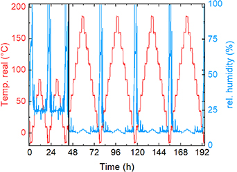
Figure 1. Temperature (left y-axis, red line) and relative humidity (right y-axis, blue) during the test cycles. The complete duration corresponds to approx 8 d. The vertical black line at 43.6 h depicts the end of the 1st part of the test.
Download figure:
Standard image High-resolution imageMechanical three-point bending tests were performed on a universal testing machine (Kern & Sohn GmbH, Balingen-Frommern, Germany) with a speed of 10 mm min−1. All tests were performed in triplicates. For optical investigations of the specimens after thermal treatment, a digital microscope Camcolms2 (Velleman, Gavere, Belgium) was used.
3. Results and discussion
For a macroscopic optical investigation, figure 2 depicts the 1st sets of samples after the thermal cycling up to 85 °C (figure 2(a)) as well as the set of samples which stayed in the climate chamber up to 185 °C, i.e. for the whole test duration (figure 2(b)). The 2nd set of improved samples is depicted later on in the form of microscopic images.

Figure 2. First set of samples (a) after 1st thermal cycle up to 85 °C; (b) after full thermal cycle up to 185 °C. The colors are correlated to the following materials: red = PLA, blue = ABS (black after thermal treatment), black = CPE, orange = PETG, white = HD-glass or HT-PLA (both molten after thermal treatment), translucent = clear basic 3D printing UV sensitive resin (brown after thermal treatment). Visible samples sizes are 10 mm × 100 mm.
Download figure:
Standard image High-resolution imageGenerally, after thermal cycling up to 85 °C, nearly no differences to the as-printed samples are visible. The samples behave thus more temperature-stable than expected due to some of the lower glass transition temperatures. Comparing 85 °C samples and 185 °C samples, however, shows strong differences. The PLA samples are completely molten after 185 °C treatment, with the melt partly flowing along the valleys of the aluminum tray, as expected according to the melting temperature (table 3). Besides, the material feels brittle and is clearly fully non-suitable for such high temperatures.
While PLA is well-known to not withstand high temperatures, ABS would have been expected to survive higher temperatures. After thermal cycling up to 185 °C, however, the material is slightly deformed and the color turned from blue to black (cf figure 3 for a nearer view), while not fully molten, as PLA.

Download figure:
Standard image High-resolution image
Figure 3. Microscopic images of samples as-printed (left panels), after treatment in the climate chamber up to 85 °C (middle panel) and up to 185 °C (right panel). The horizontal width of the images is 15.9 mm, the intact samples have a width of 10 mm.
Download figure:
Standard image High-resolution imageThe CPE samples belong to the few ones which have fully retained their shape, without visible changes in the surface roughness, gloss, or dimensional changes, making this material optically promising for high-temperature applications.
PETG, HD-glass and HT-PLA are known to be autoclavable at 121 °C [5], opposite to ABS. PETG, however, is also fully molten after temperatures cycling up to 185 °C, although the maximum melting temperature is not reached. It must be mentioned that it is not brittle, but the molten strains are slightly elastic and do not break easily. Nevertheless, melting completely makes this material again fully unsuitable for high-temperature applications.
HD-glass is a special PETG with improved temperature resistance. This material does not keep its form, but shows less melting than PETG, shows a shiny surface and is relatively strong in the new shape, similar to common PETG. HT-PLA, on the other hand, is completely molten, flowing through the aluminum tray like PLA, as expected due to the low melting point.
Finally, the originally translucent SLA printed samples became brownish, but completely retained their shape, which could be expected for thermosets.
The second set of samples, consisting of SLA printed Clear Basic resin and High Temp Resin type D, behaved as expected—the Clear Basic resin samples again became brownish and retained their shape, while the samples from high Temp Resin type D slightly changed their color from pink to orange and did not change their shape, either.
From these first impressions, it can be assumed that CPE and the SLA resin samples may behave ideally under high-temperature applications. Next, figure 3 depicts microscopic images regarding the first set of samples of the surfaces as-printed, after heat treatment up to 85 °C, and after thermal cycling up to 185 °C. Again, nearly no differences between the as-printed samples (left panels) and the samples after temperature cycling up to 85 °C are visible. The samples treated at higher temperature, however, show in most cases substantial modifications, as it could already be recognized in the macroscopic overview images.
For ABS, the color change from blue to black is most obvious. Besides, the sample surface looks clearly molten due to its shiny impression. For CPE, oppositely, there is no difference in the sample surface visible. As mentioned above, no deformations were visible, either.
PETG and HD-glass are both molten after the 185 °C thermal cycles, with HD-glass still showing artifacts of the printing lines, i.e. being not as severely molten as the next samples. PLA and HT-PLA seem to show a phase separation along the surface which was not investigated further since these samples are highly brittle after the high-temperature treatment and thus unsuitable for further tests.
In the SLA printed samples, independent from the UV after-treatment duration, there are several micro-cracks visible, suggesting the samples may splinter into large numbers of fragments during mechanical tests.
Next, figure 4 depicts microscopic images of the second set of samples. The samples SLA-d and SLA-e again show clear breaking lines after high-temperature treatment at 185 °C, as in figure 3. Here, however, the microcracks have a different orientation. This finding clearly shows that the formation of these microcracks is related to the printing orientation and suggests that possibly different mechanical properties can be expected in the three-point bending tests.

Figure 4. Microscopic images of improved samples as-printed (left panels), after treatment in the climate chamber up to 85 °C (middle panel) and up to 185 °C (right panel). The horizontal width of the images is 15.9 mm, the intact samples have a width of 10 mm.
Download figure:
Standard image High-resolution imageInterestingly, the high-temperature resin 'type D' also shows modifications upon heat treatment. Especially for SLA-f, unexpectedly, cracks are visible on the sample surface.
In both cases, comparing the colors of the as-printed samples and the ones treated at 85 °C (SLA-d and SLA-e) or the surface structures (SLA-f and SLA-g), respectively, it is clearly visible that the professional Wash and Cure machine results in a higher degree of photopolymerization and a more even surface structure without visible cracks, respectively.
Next, figure 5 shows the mechanical tests of the samples of the first set. To avoid too many lines per graph, a representative graph was chosen from each triplicate regarding force and elongation. It should be mentioned that deviations between nominally identical samples are quite low for the FDM printed samples (in the range of 1% and 2% regarding the force and up to 5% regarding the elongation at break), while SLA printed samples show a broader variety of approx 10% for force and elongation at break, especially in case of the high-temperature samples due to the irregular micro-cracks.

Download figure:
Standard image High-resolution image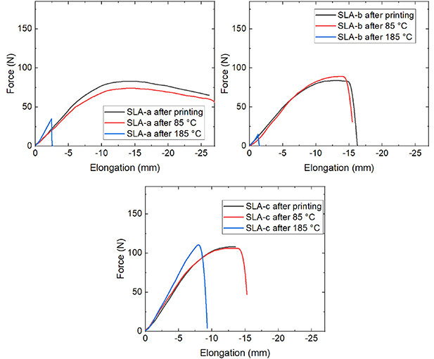
Figure 5. Results of three-point bending tests of samples of the 1st set from the different materials after printing (black curves), after thermal cycling up to 85 °C (red curves) and after thermal cycling up to 185 °C (blue curves). Missing blue curves could not be measured since the samples fully lost their original shape.
Download figure:
Standard image High-resolution imageFor many samples, such as ABS, HT-PLA, SLA-b (UV cured for 10 min/side) and SLA-C (UV cured for 1 h/side) black and red curves, measured for the as-printed samples and the specimens after thermal cycling up to 85 °C, are identical within the measurement accuracy. For other samples, such as CPE, PETG, HD-glass and PLA, significantly higher forces are visible. However, the elongation at break is significantly reduced for PLA, showing that this material became much more brittle. This effect of crystallization during thermal treatment especially of PLA above the glass transition temperature (∼60 °C), but also of other 3D printing polymers is well-known [25–27]. Only for SLA-a (not post-treated), a slight reduction of the force at break isvisible.
This changes completely, as expected from the previous images, for the samples present in the temperature cycles up to 185 °C. The ABS sample, which changed color and was also slightly molten, here unexpectedly now shows a significantly increased force at break, while at the same time the elongation at break is significantly reduced. The effect is similar to the partial crystallization of PLA at lower temperatures, which fits to the glass transition temperature of ABS of approx 105 °C.
Next, CPE breaks at strongly reduced forces. In spite of its possibility to retain its shape very well, this finding makes CPE unsuitable for high-temperature applications.
Interestingly, for the SLA printed samples, a clear difference between the long (1 h per side) UV-treatment duration of SLA-c samples and the shorter (10 min per side) UV treatment (SLA-b) or the samples without post-curing (SLA-a) is visible. In spite of the clearly visible micro-cracks, sample SLA-c showed a more brittle behavior, breaking as smaller elongations, but without reduction of the necessary force.
While none of these samples showed both sufficient mechanical properties and dimensional stability after a temperature treatment of 185 °C, the SLA-c samples most promising in terms of maintained dimensions and not too strongly reduced maximum force. This is why the 2nd set of samples was printed with SLA under improved printing conditions (with support under an angle of 45°), partly with improved curing (in a professional Wash and Cure machine), and partly with a high-temperature resin instead of the common Clear Basic 3D printing UV sensitive resin. The results of these tests are depicted in figure 6.

Figure 6. Results of three-point bending tests of improved samples (2nd set) from the different materials after printing (black curves), after thermal cycling up to 85 °C (red curves) and after thermal cycling up to 185 °C (blue curves).
Download figure:
Standard image High-resolution imageOn the one hand, using the professional Wash and Cure equipment clearly led to better results, as visible by comparing SLA-e (SLA-g) with SLA-d (SLA-f). This is only valid, however, for the mechanical properties of the as-printed samples and those investigated after thermal treatment up to 85 °C. None of the samples depicted here shows sufficient mechanical properties; oppositely, they are all lower than those of sample SLA-c after treatment at 185 °C. This could indicate an influence of the angle of orientation of the sample relative to the printing bed on the mechanical properties, or could indicate too intensive curing with respect to an application in the high temperature range up to 185 °C.
Unexpectedly, the high-temperature resist (SLA-f and SLA-g) has not only significantly lower forces at break than the common Clear Basic resin directly after printing and after temperature treatment up to 85 °C, but shows even further reduced mechanical properties after heating up to 185 °C. It should be mentioned that these high temperatures were approached four times, for several hours per temperature sweep, so that the situation in our test is harsher than for a short-time heating to similar temperatures.
Figure 7 shows exemplary cross-section microscopies of these samples after break.

Figure 7. Optical microscopy images of the cross-sections after break of the improved samples. (a) SLA-e as-printed; (b) SLA-e after 85 °C; (c) SLA-e after 185 °C; (d) SLA-g as-printed; (e) SLA-f as printed; (f) SLA-f after 185 °C.
Download figure:
Standard image High-resolution imageGenerally, a deeper look reveals in all cases the typical fine lines corresponding to the printed layers. More important information is given by the overall optical appearance of the broken areas. However, brittle failure occurs generally as a mixture of intra- and inter-laminar failure, with a larger influence of the bending pin than of the printing orientation.
Interestingly, the inner part of sample SLA-f after temperature treatment at 185 °C (figure 7(f)) looks identical to the inner part of the as-printed sample (figure 7(e)), while the outer part shows a different color. This may be an explanation for the nominally high temperature resistance of parts printed from this material—possibly, short-term temperature treatment only influences the surface so that larger samples will contain enough uninfluenced material in the inside to stay mechanically stable.
Finally, figure 8 depicts all maximum forces measured in this study for an easier comparison, separated into FDM printing polymers and SLA specimens.

Figure 8. Maximum forces for the materials under investigation.
Download figure:
Standard image High-resolution image
Here it is clearly visible that for the as-printed samples, PLA and SLA-e (Clear Basic resin, printed under an angle of 45° and cured in the professional Wash and Cure machine) are advantageous in terms of the maximum force. For thermal cycling up to 85 °C, HT-PLA and SLA-e are favorable, unexpectedly directly followed by common PLA. For the high-temperature cycling up to 185 °C, however, only ABS and SLA-c showed considerable maximum forces.
These results show that amongst the materials investigated in this study, especially ABS and SLA resin after long post-exposure to UV irradiation have to be investigated further, modifying the printing parameters, especially the angle related to the sample orientation on the printing bed, and the materials by testing different producers. For maximum temperatures below 185 °C, also PETG and HD-glass have to be taken into account, while PLA and HT-PLA have to be tested in more detailed temperature test regarding their maximum utilization temperature.
4. Conclusion
The recent study serves as a base for future investigations of 3D printing materials for high-temperature applications, such as structural elements, heat shields or inner parts of microsatellites. Especially ABS and SLA resin with long UV post-curing showed relatively high forces at break after temperature cycling up to 185 °C, while the elongation at break was reduced in both cases, as compared to the as-printed samples. PETG, HD-glass and HT-PLA, which are known to be autoclavable, showed nearly full melting after being cycled up to 185 °C, as expected due to their melting points, with HT-PLA as well as common PLA becoming very weak and breaking at smallest forces. A special high-temperature resin did not show significantly improved properties after temperature cycling up to 185 °C, as compared to the aforementioned materials.
The next investigations will concentrate on testing mechanical forces and dimensional changes after thermal cycling with different maximum temperatures between 85 °C and 185 °C, as investigated here, and different numbers of cycles. For ABS, materials from different producers will be tested with different printer settings, while the SLA printed specimens will in addition be subjected to different sample orientations as well as UV treatment durations, and more SLA resins will be investigated. In this way, it is planned to prepare a set of materials which can be printed on low-cost 3D printers without high-temperature option and used at high temperatures, enabling the preparation of parts of microsatellites for the LEO by simple means in each research group working in this area.
Funding
The study was partly funded by the German Federal Ministry for Economic Affairs and Energy via the AiF, based on a resolution of the German Bundestag, Grant Number KK5129708TA1, and by the Silesian University of Technology Rector's Grant No. 14/030/RGJ21/00110. We acknowledge funding of the climate chamber by the Ministry of Culture and Science of the State of North Rhine-Westphalia via the 'Zukunftsfonds'.
Authors' contributions
Conceptualization, GE, TB and AE; formal analysis, AE; investigation, GE, JLS, JU, ED and AE; writing—original draft preparation, AE and TB; writing—review and editing, all authors; visualization, AE. All authors have read and agreed to the published version of the manuscript.