
Abstract
Cerium conversion coatings, which have been used as protective coatings for aluminum alloys, are now being considered as an alternative to chromium conversion coatings for improving the corrosion resistance of magnesium alloys. This study investigated the evolution of conversion coatings on an AZ31 magnesium plate immersed in 0.05 M cerium nitrate solution. In addition to the expected growth of the conversion coating with immersion time, it was found that there may be an inherent adhesive weakness within the coating layers, which then led to partial detachment of the coatings from the magnesium plate while drying the samples at room temperature. Cross-sectional transmission electron microscopy characterization of conversion coatings revealed a three-layered structure comprising of porous, compact, and fibrous layers sequentially formed on top of the magnesium plate. Furthermore, the weakest bonding was identified as the interface between the compact and the fibrous layers. Based on the identified layer morphology and the respective composition, a possible formation mechanism for cerium conversion coating on magnesium alloy was proposed, which would serve as a basis for improving the adhesive strength of the coating on magnesium substrate. © 2004 The Electrochemical Society. All rights reserved.
Export citation and abstract BibTeX RIS
In light of their low density and high specific strength and stiffness, magnesium alloys are extensively used in electrical appliance and automobile industries.1 2 However, most magnesium alloys are chemically reactive and tend to suffer severe corrosion during service.2 3 Surface modification treatments are therefore indispensable for improving the corrosion resistance of magnesium alloys, which includes anodizing,4 5 6 7 8 conversion coating,4 9 10 11 12 13 14 15 16 17 electroless nickel plating,18 and pure magnesium coating via physical vapor deposition (PVD).19 Among the various surface modification techniques, conversion coating treatment is known for its low cost and simplicity in operation. For example, chromate conversion coatings have been extensively applied to magnesium alloys because of their simplicity in production and excellent corrosion resistance.9 10 However, the toxicity of hexavalent chromium ions in the solution and exhaust fumes has imposed a strict restriction on the use of chromate conversion coatings. In seeking alternatives to chromate conversion coating, nonchromate solutions have recently been developed, such as phosphate,4 phosphate/permanganate,11 12 stannate,13 14 and solutions containing salts of rare earth metals15 16 or cobalt.17
The rare earth conversion-coating process is recognized for its simple electrolytic constituents that usually contains nitrate, sulfate, and chloride of rare earth metals such as cerium, lanthanum, and neodymium.15 16 20 21 22 23 This simple electrolyte makes it easy to maintain and recycle, and more importantly, the solution is considered to be friendly to the environment.21 Therefore, many efforts have been made to investigate how the solution composition affects the formation and properties of the conversion coatings, especially those on aluminum alloys.20 21 22 23 In contrast to aluminum alloys, rare earth conversion coatings on magnesium alloys are less well studied, probably because of the later emergence of magnesium alloys as structural materials. Nevertheless it has been noted that in applying rare earth coatings on aluminum and magnesium alloys, severe cracking tends to occur once the coating is thick enough to adequately protect the substrate, thus leading to poor coating adhesion to the metallic substrate.15 23 In this study, the detailed microstructure of cerium conversion coatings on AZ31 magnesium plate is characterized using scanning electron microscopy (SEM), cross-sectional transmission electron microscopy (TEM), and glancing angle X-ray diffraction (XRD). From this microstructural information, the interface that exhibits the lowest bonding strength is identified, and the formation mechanism of cerium conversion coating on magnesium alloy is proposed.
Experimental
Conversion coating treatment.—
The conversion coatings were made on an AZ31B magnesium plate. The plate with a size of  was mechanically polished up to 2400 no. emery paper, rinsed with deionized water, and cleaned in acetone ultrasonically, followed by drying using a stream of hot air. Prior to immersion, the weight of the coupon was measured by an electronic balance with an accuracy of 0.1 mg.
The solution for conversion-coating treatment was 0.05 M cerium nitrate with pH experimentally measured to be 5.2 at 30°C. The solution was kept at 30°C and agitated using a magnetic stirrer throughout the immersion. The immersion time was set to range from 0.5 to 20 min for investigating the growth kinetic of the conversion coating. After immersion, the coupons were thoroughly washed in deionized water, dried overnight, and then reweighed, allowing for the measurement of the weight difference of the plate before and after immersion. The weight gain of the specimen was defined as the weight difference per unit treated area of the plate.
Microstructural characterization.—
The surface morphology of the conversion coating was investigated using SEM. The thickness of the coating was measured on cross-sectional SEM micrographs. The phase of the coating was identified using glancing angle XRD with an incident angle of  Cross-sectional TEM was employed to reveal the detailed microstructure of the coating. Additionally, the composition associated with the distinct features observed in the coating was measured via energy-dispersive spectrometry (EDS) in TEM using an electron probe of 10 nm in diameter. The thickness of each distinct layer was reported as an average of at least ten measurements made on TEM micrographs. Finally, the structure of the coating was identified using the electron diffraction technique.
Results
Weight gain and total coating thickness.—
Figure 1 shows the weight gain and total coating thickness as a function of the immersion time. During the early stages of immersion, both weight gain and coating thickness rapidly increased with the immersion time. Then, the weight gain increased at a constant rate, while the coating thickness increased at a decreasing rate as the immersion proceeded, leading to a saturated coating thickness of approximately 3 to 4 μm after 10 min of immersion. This saturation in coating thickness is consistent with the observation made by Dabalà et al.16 who noted that the thickness of the coating rapidly developed in the first 30 s, and then remained nearly constant when treating an AZ63 magnesium alloy in a  solution. Furthermore, the saturation in coating thickness while the weight gain continuously increased with increasing immersion time suggests the coating became more and more compact as the immersion continued.
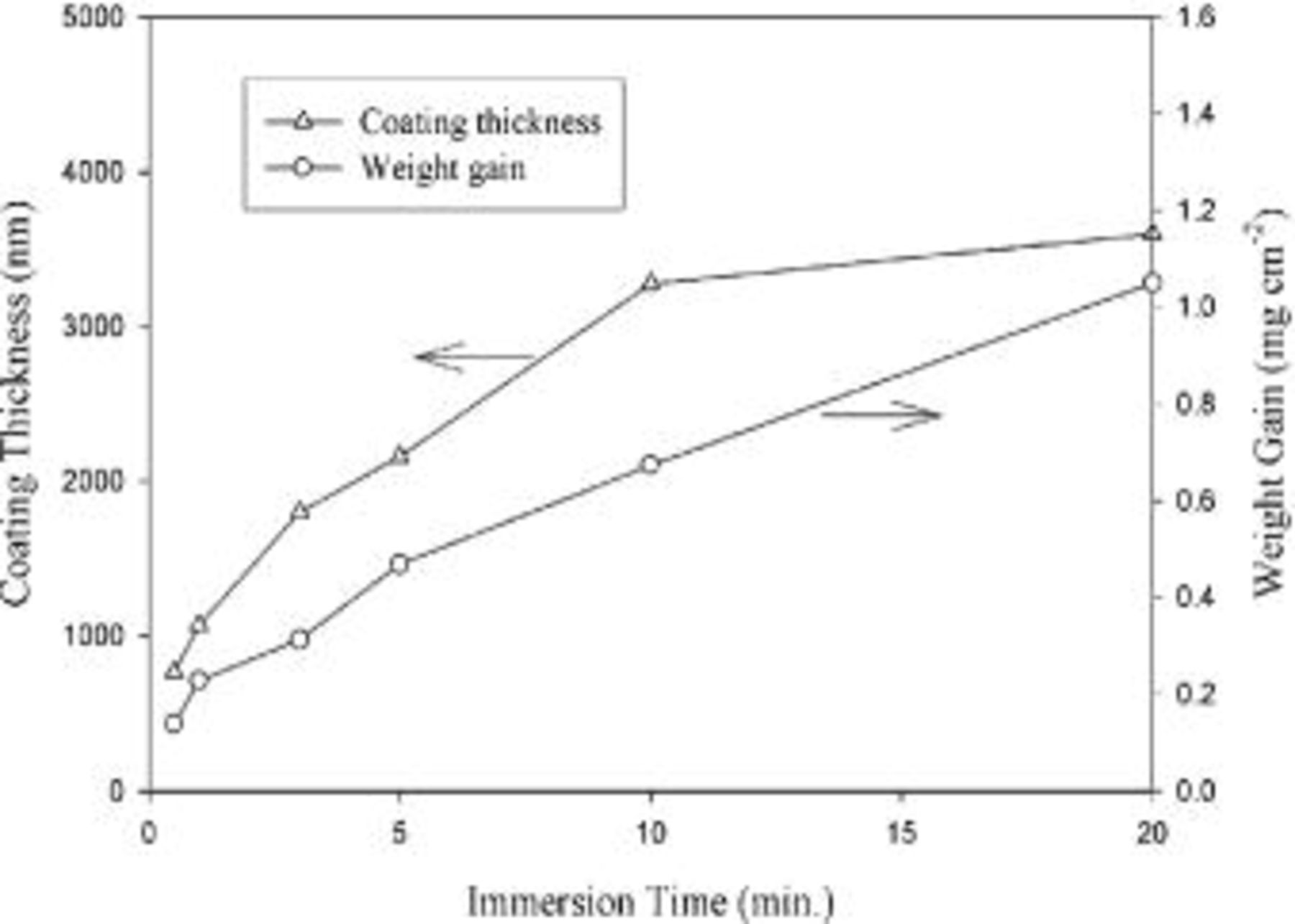
Figure 1. Weight gain and total thickness of cerium conversion coatings on AZ31 magnesium plates as a function of the immersion time.
Surface morphology.—
After 0.5 min of immersion, the surface of magnesium plate was dotted with island-like particles, as shown in Fig. 2a. These particles aligned themselves in rows along the scratches induced during mechanical polishing. Apparently, the coating reaction occurred preferably at the scratches that had a higher energy due to the plastic deformation caused by mechanical polishing. After 1 min of immersion, the surface of the plate was covered with a complete coating on which numerous microcracks formed (Fig. 2b). Up to this stage of immersion, the tracks of the scratches remained visible, suggesting the coating was relatively thin and predominantly developed by means of the coalescence of island-like particles. As the immersion proceeded to 3 min, the coating was thick enough to mask the scratches that existed prior to immersion. Meanwhile, cracks with larger crack-width developed, as indicated by the arrow in Fig. 2c. These cracks divided the whole coating into pieces separated by relatively large cracks. Several relatively small microcracks were observed within each piece, as can be seen in Fig. 2c-f. Furthermore, the width of the cracks notably increased as the immersion continued. To understand whether cracks formed during the growth of the coating in the solution or upon drying at room temperature, the plate was withdrawn from the solution and immediately observed under an optical microscope. No cracks were observed on the plate withdrawn from the solution. Cracks in the coating occurred as a result of drying process. This cracking behavior can be understood if the coating formed in the solution contained water molecules. The evaporation of water molecules caused shrinkage in volume, allowing cracks to form. Obviously, the stress associated with shrinkage increased with the thickness of the coating. Larger stress induced more severe cracking (Fig. 2d-f), and even worse, caused partial detachments of the coating from the plate. This detachment also indicates that the coating had poor adhesion to the magnesium substrate. Such an inadequate adhesion becomes the major task to overcome before the application of cerium conversion coatings as protective coatings for magnesium alloys. Figure 3 shows a close-up view of the surface morphology of the coating formed after 20 min of immersion. The coating consisted of interlaced fibers with diameters ranging from several tens to a couple of hundreds of nanometers.
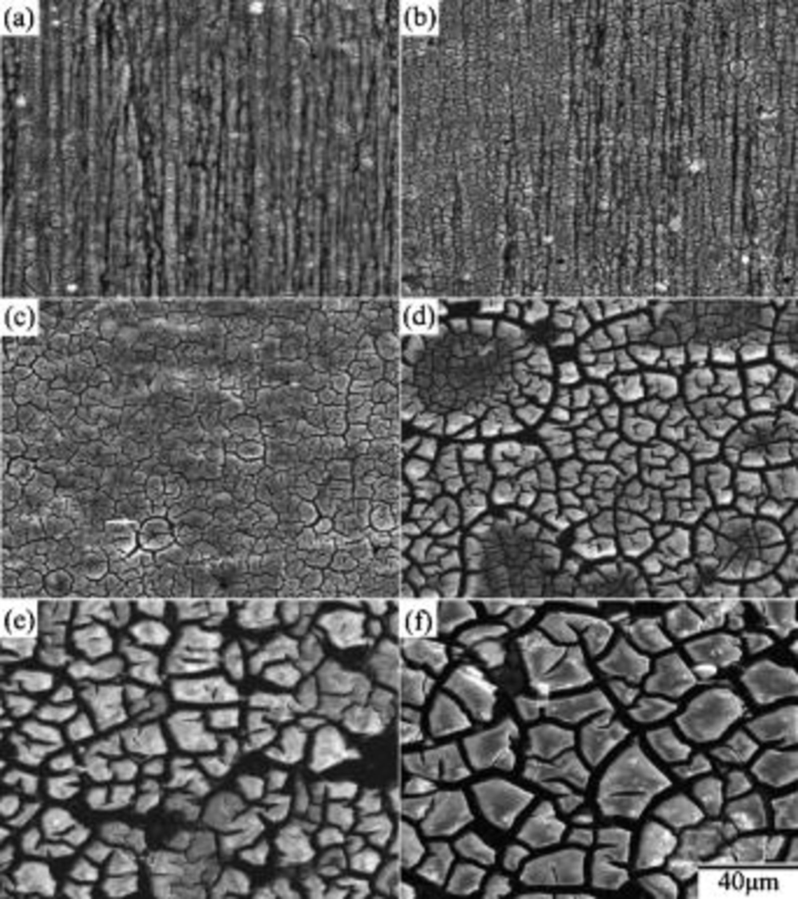
Figure 2. Surface morphology of cerium conversion coatings on AZ31 magnesium plates immersed in the solution for (a) 0.5, (b) 1, (c) 3, (d) 5, (e) 10, and (e) 20 min.
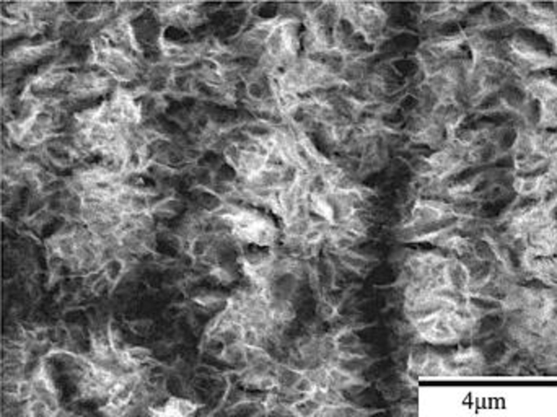
Figure 3. A close-up view of the surface morphology of the coating formed after 20 min of immersion.
Cross-sectional TEM characterization.—
Figure 4 shows that prior to immersion, the surface of as-polished AZ31 plate was covered with an oxide layer of approximately 50 nm. The existence of the oxide layer indicates magnesium alloys are indeed active when exposed to the ambience. Figure 5a shows that this air-formed oxide film has been completely replaced by the conversion coating after 0.5 min of immersion. Furthermore, the coating exhibited a three-layered structure with a porous magnesium and aluminum hydroxide/oxide layer (marked as 1 in Fig. 5a) as an under layer intimately in contact with the magnesium substrate, a rather compact layer (marked as 2 in Fig. 5a) as an intermediate layer, and a fibrous layer (marked as 3 in Fig. 5a) as the major overlay. The composition of the distinct layers was characterized by EDS analyses shown in Fig. 5c-e. The layer adjacent to the substrate contained magnesium, aluminum, and oxygen, suggesting this layer was primarily a mixture of magnesium and aluminum hydroxides and oxides. Moreover, it was noted that the ratio of aluminum to magnesium signals detected on the porous layer was significantly higher than that on the substrate, as can be seen by comparing Fig. 5b-c. Except for magnesium and oxygen, cerium was detected in both compact and fibrous layers, which appeared to have a similar composition. Both could be a mixture of cerium and magnesium hydroxides and oxides. It is also noted that the fibrous layer contributed to the greatest coating thickness, although this layer formed discontinuously. The discontinuity of the fibrous layer correlates well with the SEM micrograph shown in Fig. 2a, which illustrated that island-like particles preferentially dotted on the scratches. Furthermore, up to this stage of immersion, the fibrous layer remained adherent to the substrate. On the contrary, this fibrous layer exhibited poor adhesion to the compact layer after 3 min of immersion. Figure 6a illustrates that the fibrous layer tended to detach from the compact layer during TEM sample preparation, whereas the compact layer, porous layer, and magnesium substrate remained adherent to each other. To study the crystallinity of the distinct layers, selective area diffraction (SAD) patterns (Fig. 6b and c) as well as dark-field image (Fig. 6e) were taken and revealed the presence of nano-sized crystals in both compact and fibrous layers. In contrast to the continuously diffused rings associated with the SAD pattern taken from the fibrous layer, the discrete spots on the rings from the compact layer suggests that the crystalline size of the compact layer was larger than that of the fibrous layer. In addition, the porous layer could be identified as an amorphous structure since the SAD pattern contained diffused halos.
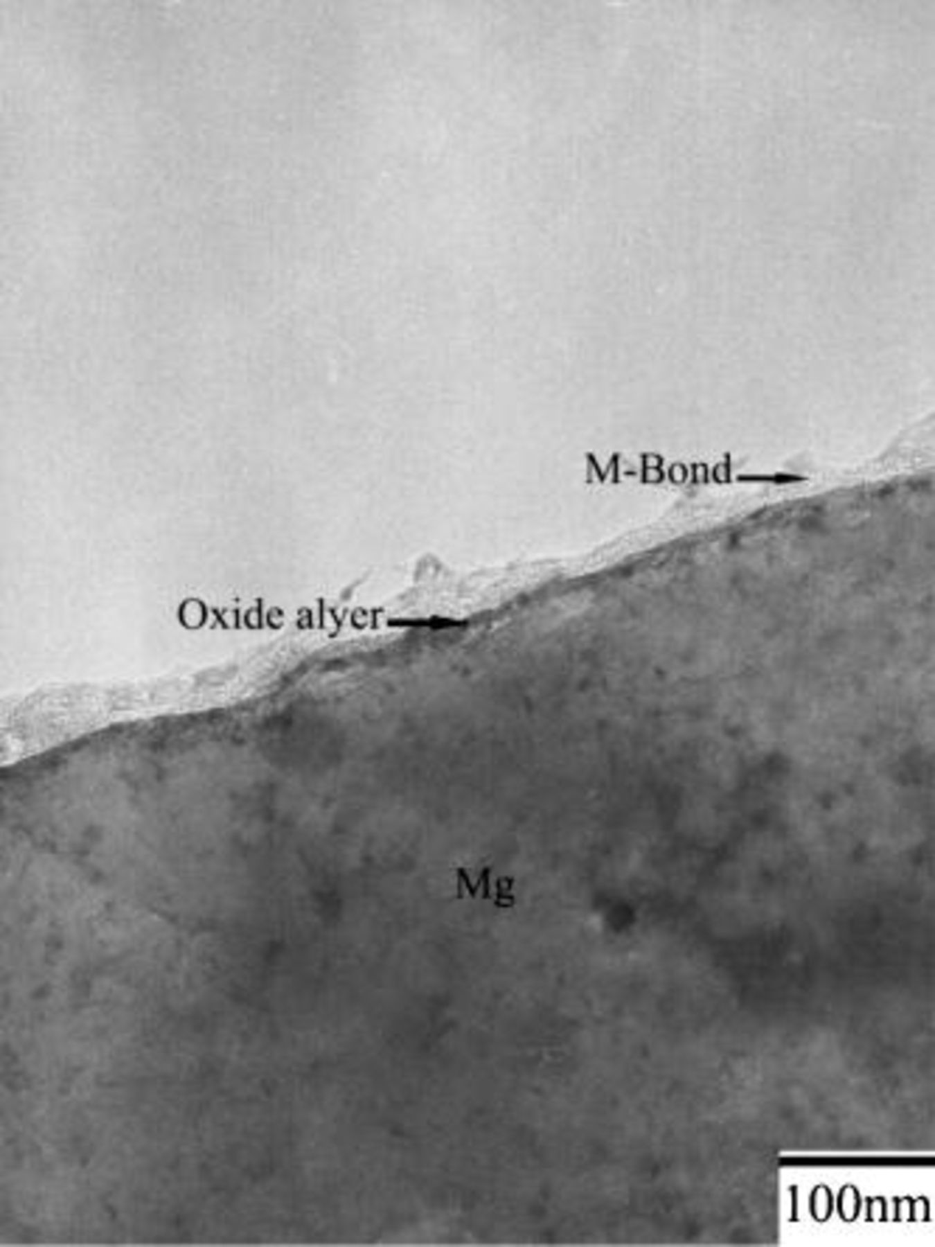
Figure 4. Cross-sectional TEM micrograph showing the microstructure of as-polished AZ31 magnesium plate.
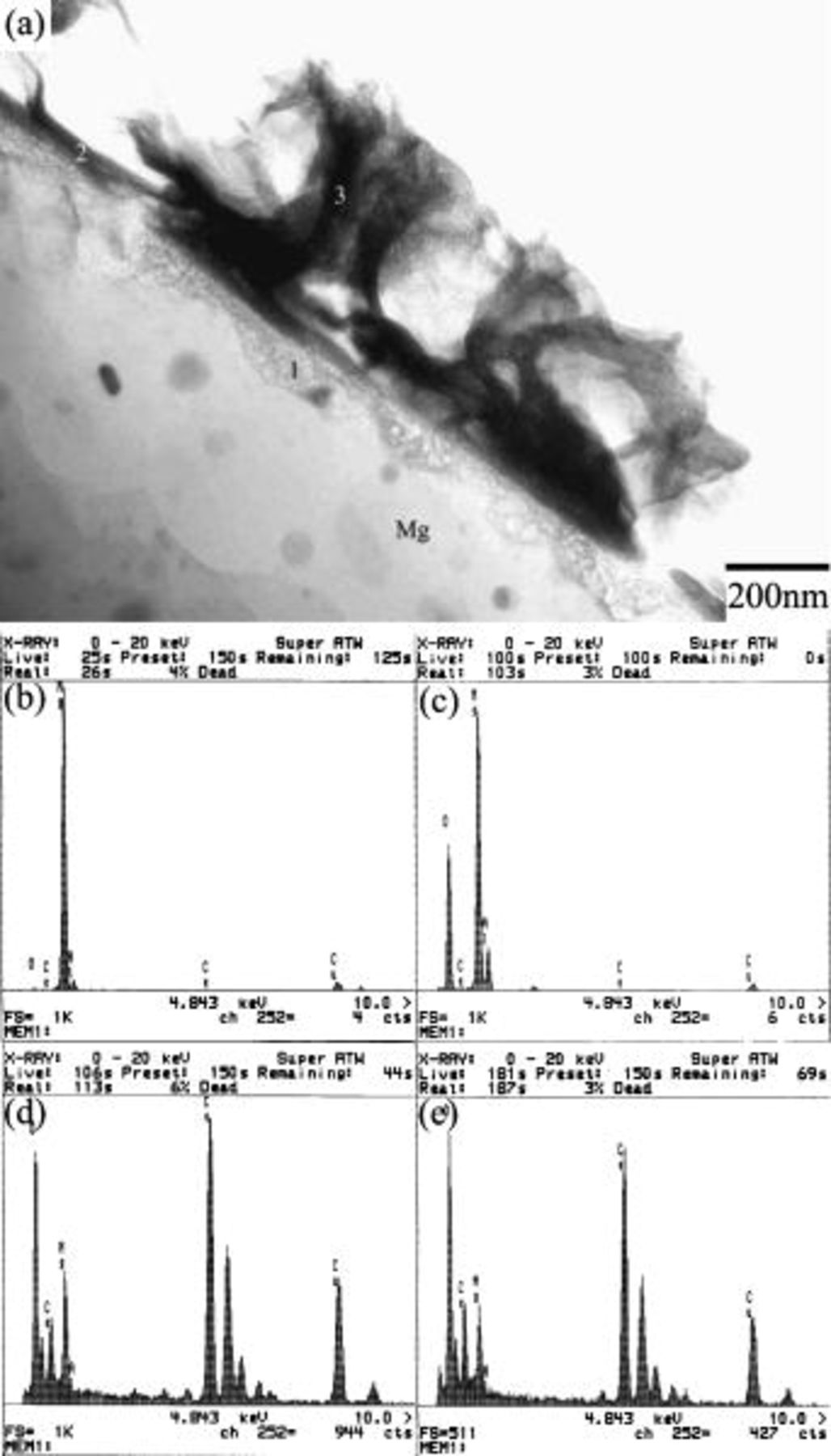
Figure 5. Cross-sectional TEM micrograph showing the microstructure of the plate after 0.5 min. of immersion: (a) the overall view of the coating, and (b)-(e) the EDS spectra taken from the substrate as well as the areas marked as 1, 2, and 3 in (a), respectively.
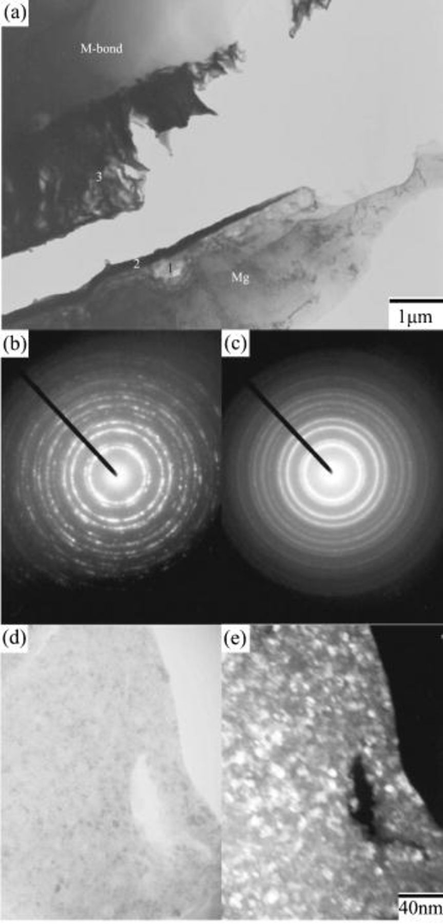
Figure 6. Cross-sectional TEM micrograph showing the microstructure of the plate after 3 min of immersion: (a) the overall view of the coating showing the detachment of the fibrous layer from the compact layer, (b) and (c) the SAD patterns taken from the compact and porous layers, respectively, and (d) and (e) the bright and dark field images of the compact layer.
Figure 7 illustrates the conversion coating was still composed of three layers up to the longest immersion studied, namely, 20 min. That is, the porous, compact, and fibrous layers sequentially formed on top of the magnesium substrate. No significant changes in the microstructure and composition of the various layers were noted as the immersion proceeded, except that the fibrous layer became denser with increasing immersion time. To understand the variation in the thickness of the distinct layers, the thickness of each layer as a function of the immersion time was measured on cross-sectional TEM micrographs. As can be seen in Fig. 8, all layers exhibited an increase in thickness during immersion, with the growth rate increased in the order of compact, porous, and fibrous layers. Since the growth rate of each layer decreased as the immersion continued, the increase in coating thickness was a characteristic of parabolic increase.
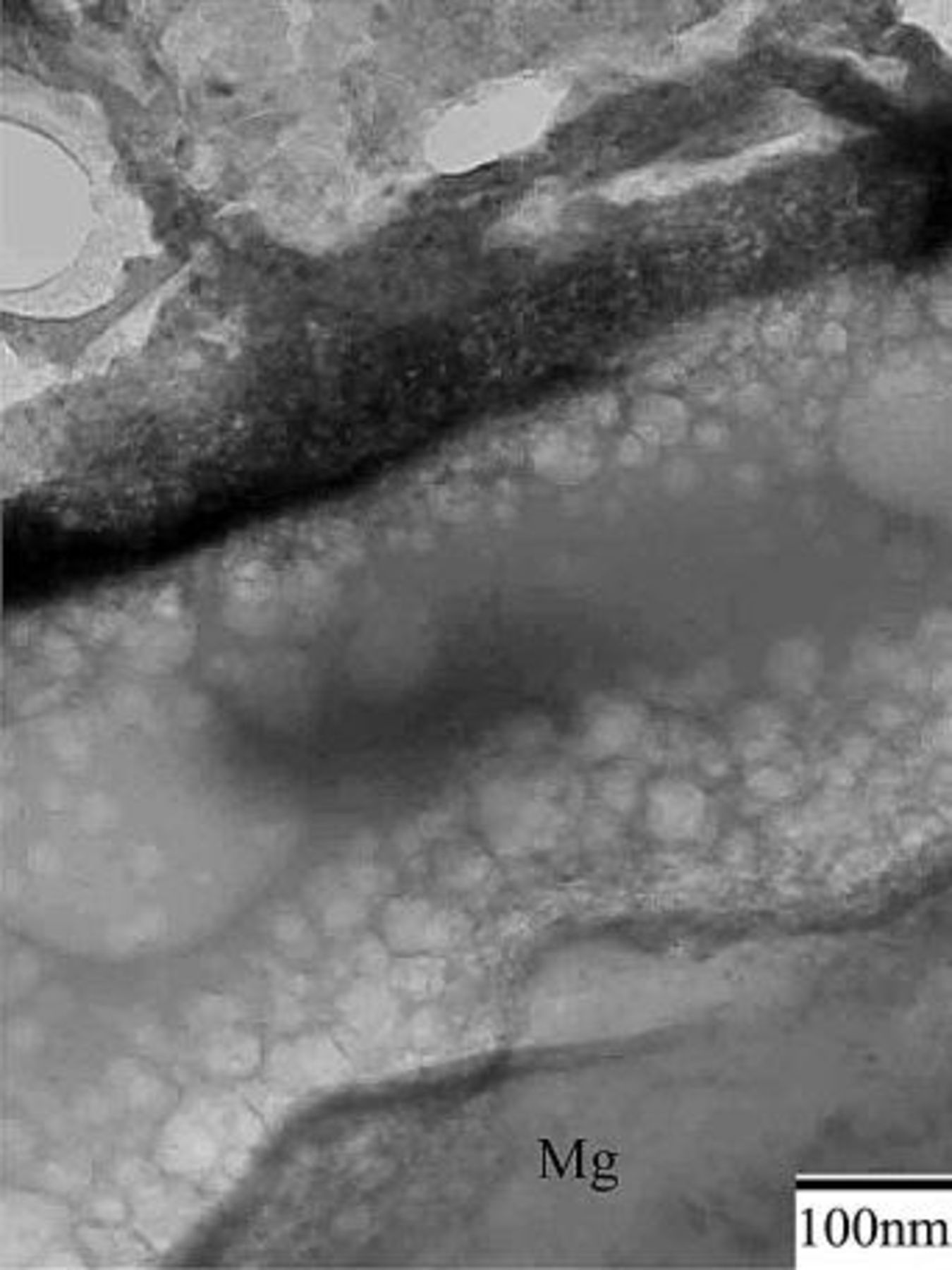
Figure 7. Cross-sectional TEM micrograph showing the microstructure of the plate after 20 min of immersion.
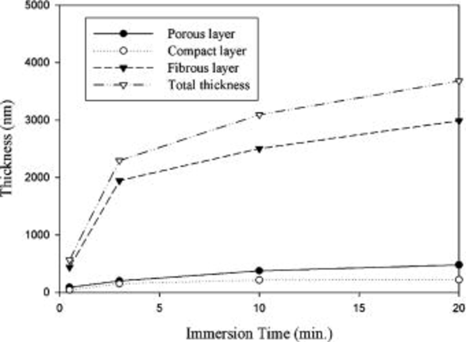
Figure 8. Thickness of the distinct layers as a function of the immersion time.
Glancing angle XRD.—
Figure 9 shows the XRD pattern of the conversion coating formed after 20 min of immersion. The peaks of the pattern could be characterized into two sets with sharp peaks coming from the magnesium substrate and relatively broadened peaks that could be assigned to the diffraction peaks associated with cerium oxide. These broadened peaks also confirm the existence of nanosized grains in the major overlay.
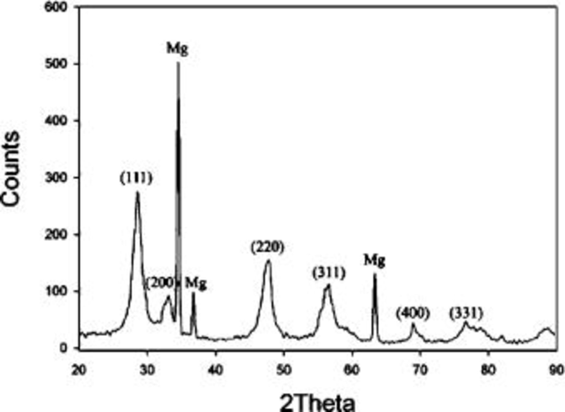
Figure 9. XRD pattern of the coating formed after 20 min of immersion.
Discussion
Figure 10 shows a scheme illustrating the evolution of cerium-conversion coatings on the AZ31 plate immersed in 0.05 M cerium nitrate solution. Upon immersing, the air-formed magnesium oxide film immediately dissolves into the pH 5.2 solution. This dissolution is due to the fact that stable species of magnesium in aqueous solutions with pH less than 8.5 are  24 After the dissolution of the oxide layer, the primary anodic reaction in the solution is oxidation and subsequent dissolution of the AZ31 plate, allowing an aqueous layer enriched with
  and
and  to form on the plate surface. Since the solubility of
  dramatically decreases in the solution with pH exceeding 4.0,24
  in this pH 5.2 solution are readily redeposited as aluminum hydroxides/oxides on the plate surface. An
  -rich layer dispersed with aluminum hydroxides/oxides is thus built up on the plate surface, as shown in Fig. 10a. Accompanying the dissolution of AZ31 plate, reduction of protons occurs in acidic solutions. This hydrogen discharge causes an increase in pH at the interface between the plate and the solution. Once the interfacial pH is high enough, the various cations in solution will precipitate as cerium hydroxides and magnesium hydroxides in sequence with increasing solution pH.24 During cerium-conversion coating treatment on an AZ63 magnesium alloy, which contains more intermetallic precipitates than AZ31 alloy, Dabalà et al.16 demonstrated that conversion coatings preferentially form on these intermetallic precipitates that serve as cathodic sites favoring the reduction of protons. This precipitation reaction due to local pH rise accounts for the results that the conversion coatings formed in the present study are primarily composed of metal hydroxides and oxides.
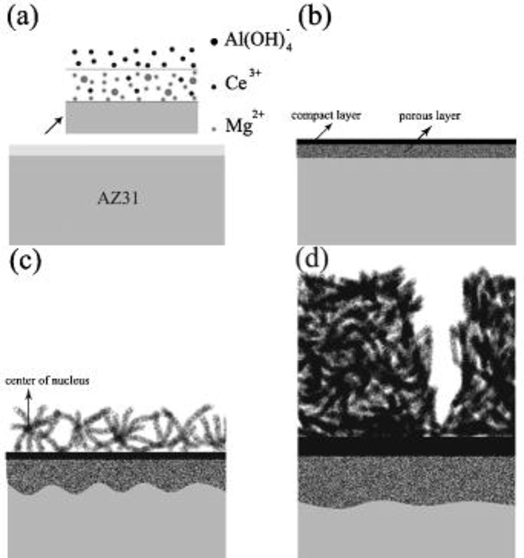
Figure 10. Schematic representation of the evolution of cerium coating on AZ31 plate immersed in cerium nitrate solution.
As aforementioned,  tends to immediately precipitate as aluminum hydroxides/oxides on the plate surface.
  accumulated on the surface also facilitates the precipitation of magnesium hydroxides once the solution pH is higher than 8.5.24 Consequently, a porous layer as a mixture composed of magnesium and aluminum hydroxides/oxides forms and intimately contacts with the AZ31 plate, as shown in Fig. 10b. The fact that the ratio of aluminum to magnesium in this porous layer is significantly higher than that of the substrate supports the formation mechanism associated with the porous layer. Following the precipitation of magnesium and aluminum hydroxides/oxides,
  become the major cation in the interfacial layer and subsequently deposits on top of the porous layer as a compact layer (Fig. 10b) on which the signals of aluminum are below the detectable limit of EDS. The absence of aluminum in the compact layer also explains
  once dissolved from the substrate, immediately precipitates as aluminum hydroxides and oxides. Because both porous and compact layers form as a result of the concomitant pH rise due to the liberation of hydrogen in conjunction with the dissolution of AZ31 alloy, both should form at the very beginning of immersion. Then, the plate is potentially passivated by both layers. The transportation of reacting ions and solution through the compact and porous layers is needed for the further coating reaction, which is limited by the diffusion of various reaction species. This diffusion-controlled reaction leads to a parabolic increase in the thickness of the distinct layers with immersion time (Fig. 8). The transportation of dissolved
  to the surface of the compact layer as well as the reduction of protons on the surface of the compact layer creates an environment suitable for the precipitation of cerium and magnesium hydroxides, leading to the formation of the fibrous layer (Fig. 10c). As the immersion continues, more fibrous metal hydroxides precipitate in the solution filling in the spaces between the existing fibers; accordingly, the fibrous layer becomes more compact. Meanwhile, the fibrous layer grows as more fibers precipitate on the existing layer, as shown in Fig. 10d.
It is generally recognized that  precipitates as cerium hydroxides in aqueous solutions with adequately high pH.24 However, the XRD pattern identifies the coating as cerium oxide, suggesting cerium hydroxides may be oxidized to form cerium oxides during the drying process in the atmosphere. This oxidation is consistent with the fact that Ce(III) tends to be oxidized to Ce(IV) when exposed to oxygen.25 In addition, the oxidation of Ce(III) to Ce(IV) in solution might result in the formation of insoluble cerium oxide as proposed by Aldykiewicz et al.26 Moreover, the broadened XRD peaks associated with cerium oxide correlates well with the nanosized crystals observed by TEM. The EDS analyses indicate that both fibrous and compact layers are mixtures composed of cerium and magnesium hydroxides or oxides. The absence of the diffraction peaks associated with magnesium hydroxides and oxides suggests that magnesium hydroxides and oxides in the coating are amorphous. This amorphous nature also correlates to the diffused halos shown in SAD pattern.
According to the morphology of the fibrous layer, instead of nucleation right on top of the compact layer, these fibers seem to nucleate in the solution located at a distance away from the compact layer/solution interface, as illustrated in Fig. 10c. This nucleation position resulted from an optimal combination in solution  concentration and pH for the precipitation of magnesium and cerium hydroxides. For example, following the formation of the compact layer, a
  -depletion layer develops, whereas the solution pH always decreases at the distance away from the interface between the compact layer and the solution since proton reduction predominately occurs on the surface of the compact layer. Consequently, a location at a certain distance from the interface has a high enough
  and pH to launch the nucleation of fibers. This type of nucleation accounts for the poor adhesion of the fibrous layer to the compact layer. However, the stress caused by desorption of water molecules is certainly the key factor inducing severe cracking and subsequent partial detachments of the coating. How the solution composition and operation parameters affect the nucleation behavior of the fibrous layer and the phase constituents of the coating, particularly its water content, will shed light on improving the adhesive strength of the overall coating to the magnesium substrate.
Conclusions
The formation of cerium-conversion coatings on AZ31 magnesium plates immersed in 0.05M cerium nitrate solution has been investigated. Results of this study can be summarized as follows:
- (1)(1) The surface of an as-polished AZ31 plate was covered with a magnesium oxide layer, which tended to immediately dissolve in the pH 5.2 solution
- (2)(2) The weight and thickness of the coating increased, respectively, at a linear and parabolic rate with increasing immersion time, allowing a saturated coating thickness to be reached while the coating weight remained to increase with the immersion time. This phenomenon suggests the coating became denser and denser as the immersion continued.
- (3)(3) The coating was comprised of three layers with a porous magnesium and aluminum hydroxide/oxide layer as an underlayer in intimate contact with the magnesium substrate, a rather compact layer as the intermediate layer, and a fibrous layer as the major overlay.
- (4)(4) Stress induced by drying the sample at room temperature caused severe cracking, which in turn, resulted in partial detachments of the coating from the substrate since the porous layer had poor adhesion to the compact layer.
- (5)(5) Cerium-conversion coatings formed on AZ31 plates were mainly composed of metal oxides and hydroxides, which precipitated in the solution with high enough pH owing to the reduction of protons. For example, the dissolution of air-formed magnesium oxide exposed the plate to be attacked by the solution, allowing a layer enriched with
 and to form at the interface between the substrate and the solution. and subsequently precipitated as magnesium and aluminum hydroxides/oxides as interfacial pH rose due to proton reduction. Then, a compact layer composed of magnesium and cerium hydroxides/oxides formed, allowing the plate to be passivated. Diffusion of the reaction species through compact and porous layers, as well as the reduction of protons created an environment, which was located at a distance away from the solution/substrate interface, for the formation of the fibrous layer.


Acknowledgments
The authors thank the National Science Council of the Republic of China, for financially supporting this research under grant no. 922216E002017. L. C. Wang, National Sun Yat-sen University, is acknowledged for her assistance with the TEM work. This study made use of the electron microscopes of National Taiwan University and National Sun Yat-sen University, supported by the National Science Council, Republic of China.
National Taiwan University assisted in meeting the publication costs of this article.