
Abstract
Silicon, as an alloy-type anode material, has recently attracted lots of attention because of its highest known Li+ storage capacity (4200 mAh/g). But lithium insertion into and extraction from silicon are accompanied by a huge volume change, up to 300%, which induces a strong strain on silicon and causes pulverization and rapid capacity fading due to the loss of the electrical contact between part of silicon and current collector. Silicon nanostructures such as nanowires and nanotubes can overcome the pulverization problem, however these nano-engineered silicon anodes usually involve very expensive processes and have difficulty being applied in commercial lithium ion batteries. In this study, we report a novel method using amorphous silicon as inorganic glue replacing conventional polymer binder. This inorganic glue method can solve the loss of contact issue in conventional silicon particle anode and enables successful cycling of various sizes of silicon particles, both nano-particles and micron particles. With a limited capacity of 800 mAh/g, relatively large silicon micron-particles can be stably cycled over 200 cycles. The very cheap production of these silicon particle anodes makes our method promising and competitive in lithium ion battery industry.
Export citation and abstract BibTeX RIS
Lithium insertion into and extraction from silicon are always accompanied by a huge volume change that causes pulverization and rapid capacity fading due to the loss of the electrical contact between part of silicon active material and the current collector.1 Because smaller sizes of Si material experience less structural damage and pulverization, extensive studies have been carried out to explore various nano-structured Si anodes and demonstrated significantly improved performance compared to micron-Si particles.2–17 Our group has developed an innovative Si anode using one-dimensional (1D) nanowires, which were directly grown on current collector. We have demonstrated their superior performance due to the excellent electrical connection between Si nanowires and the current collector as well as effective release of the strain inherent in the nature of one-dimensionality.18, 19 The same idea has also been demonstrated on germanium nanowires.20 Furthermore, we have carried out detailed investigations on SiNWs' structure and impedance change21 and the solid electrolyte interphase (SEI) formation22 during lithium intercalation. However, nanostructured Si were often produced by complicated processes, such as high energy ball milling,5 template-assisted synthesis,11 or silane chemical vapor deposition (CVD).16, 18 Hence cheaper process of Si anode is highly desired.
Conventionally when Si particles are used as anode material, they are mixed with polymer binders, such as polyvinylidene fluoride (PVdF), and conductive additive, usually carbon black, in an organic solvent, such as N-methylpyrrolidone (NMP), to produce a viscous slurry. Then the slurry is bladed onto a copper current collector and dried to form the anode electrode. The Si anode electrode produced this way usually shows rapid capacity fading due to loss of contact issue.23 Li et al. has demonstrated that Si nano-particles showed better performance than Si micron-particles but still displayed severe capacity decay (∼50%) after just 20 cycles.24 Yoo et al. and Guy et al. have performed detailed studies on the binding mechanism of polymer in a composite electrode film.25–28 In a concentrated and viscous particle/polymer mixture such as electrode slurry, a three-dimensional network is formed by polymer chains adsorbed on the particles. After the solvent evaporates, the dried composite electrode retains the memory of the morphology in the wet state and the particles are tightened together by the polymer chains. The charge of Li+ into the Si anode leads to swelling of the electrode layer, in which carbon black powder had been added to compensate for the poor conductivity of Si particles. During the Li+ discharge period, Si particles contract as a result of the de-alloying reaction, but the electrode layer still remains swollen because thepolymer chain is not elastic enough. The net result after charge–discharge cycling is a breakdown of the conductive network between the Si and the carbon particles, which leads to an increase in the internal resistance. This process is illustrated in Fig. 1a. An abrupt increase in internal resistance during Li+ discharge causes an earlier approach to the discharge cut-off voltage so that the de-alloying reaction is not completed and Si remains in a partially lithiated state. After repeated cycles, Si anodes are degraded because of successive accumulation of Li+ ions inside the Si anode matrix. With this understanding, Chen et al.29 successfully synthesized an elastomeric binder system combined with an adhesion promoter that improved the cyclability of Si anode. Liu et al.30 also reported that the cycle life of Si electrodes can be greatly improved using a binder containing the elastomeric styrene butadiene rubber (SBR) and sodium carboxymethyl cellulose (CMC). These improvements were explained in that elastic polymers can to certain extent follow the expansion and contraction of Si particles during Li+ cycling, and thus encounter less issues with the loss of contact as shown in Fig.1a.

Figure 1. (Color online) Schematic illustration of the morphology change of Si particle films before and after Li+ charge–discharge cycling. (a) Si particle film on SS substrate prepared with conventional slurry method, where the small black particles indicate carbon black and green lines indicate PVdF chains. After cycling, the Si particles loose electrical contact with its surrounding particles. (b) Si particles fused together and bond onto SS substrate by a-Si inorganic glue, where blue rings indicate a-Si coating. After cycling, the particle film still maintains an all-connecting porous structure, where no loss of electrical contact occurs.
In this report, we replace the polymer binder with amorphous Si (a-Si) inorganic and conducting glue, which is conformally coated onto Si particles. The a-Si layer can also alloy with Li and expands and contracts at the same ratio with Si particles, effectively connecting all the Si particles electrically with the current collector during Li+ intercalation. As indicated in Fig. 1b, the Si particles are fused together and bond onto stainless steel (SS) current collector by a thin layer of deposited a-Si. Thus the loss of electrical contact issue caused by lack of elasticity of polymer binder is avoided and good cycling performance is obtained for both Si nano-particles and micron-particles. The voids between Si particles are essential because they can accommodate the volume expansion of Si particles during Li+ charge. For this Si particle film, no carbon particles as conductive additive are necessary because the all-Si-connecting network provides an excellent electron pathway. We can also easily achieve a mass loading of up to 3 mg/cm2, which is significantly higher than our CVD grown SiNWs (∼0.3 mg/cm2). Excitingly, we can even cycle relatively large 8 μm (diameter) Si particles very well when limiting the Li+ insertion amount.
Experimental
Different than conventional slurry method, we used an entirely new method to prepare Si anode with Si particles as active material. Si nano-particles or micron-particles were mixed with 10 wt % polymer binder polyacrylonitrile (PAN) in dimethylformamide (DMF) solvent to produce a viscous slurry. The slurry was bladed onto stainless steel (SS) foil current collector and dried to form an electrode film. Then we carbonized the PAN polymer in the Si particle film at 700°C under inert atmosphere. After carbonization, weperformed silane CVD at 500°C to conformally deposit a layer of a-Si, which is usually boron doped to increase conductivity. The deposited a-Si acted as inorganic glue, which fuses all the Si particles together and bind them onto the underlying SS substrate to form a continuous and porous Si film.
We chose three sizes of Si particles, with average diameters of 200 nm, 8 μm, and 15 μm, as the active material. All three sizes of Si particles were purchased from Sigma–Aldrich Corporation and used as obtained. Figures 2a–2c show the SEM images of the final film electrodes using Si particles of 200 nm, 8 μm, and 15 μm, respectively. Various sizes of Si particles are mixed with polymer binder PAN (9:1 wt) in DMF solvent to produce a viscous slurry. The slurry was spread onto SS foil current collector (∼13 μm thickness, type 304) using doctor blading and dried in vacuum oven to obtain a Si particle film. This SS foil supported Si film was cut into small round disks (0.5'' diameter) using a puncher. These disks were loaded into a SiH4 CVD tube furnace which uses a 1-in. quartz tube. The furnace was pumped to vacuum, purged with pure argon then heated to 700°C for 2 h to carbonize the PAN polymer in the Si particle films. After carbonization, the temperature of the furnace was lowered to 500°C for SiH4 CVD. Two compressed gases of 2% silane balanced in argon and 100 ppm B2H6 balanced in argon were flowed simultaneously to produce boron doped a-Si deposition. Flow rate of SiH4/Ar was 50 sccm and B2H6/Ar 5 sccm. The pressure inside the tube furnace was controlled at a constant of 20 Torr and the CVD time was set 12 min. The deposited a-Si acts as an inorganic glue, which fuses all the Si particles together and also bind them onto the underlying SS substrate to form a continuous and porous Si film. The mass loadings of the Si active material were accurately determined by measuring the weight changes of the substrate using a microbalance (Sartarious SE2, 0.1 μg resolution).
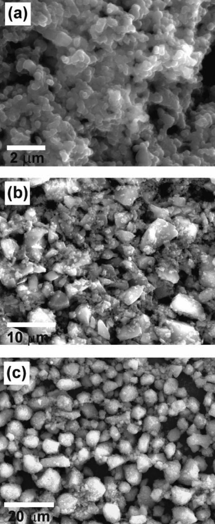
Figure 2. (a), (b) and (c) SEM images of Si particle films prepared by inorganic glue method using Si particles of diameters 200 nm, 8 μm, and 15 μm, respectively.
The anode performance of these Si particle films bond onto SS current collectors were tested in coin type half cells. Coin cells (2032 type) were made using the as-made disk as working electrode, Celgard 2250 separator, and Li metal foil as counter electrode. The electrolyte was 1.0 M LiPF6 in 1:1 w/w ethylene carbonate:diethyl carbonate (Ferro Corporation). The coin cells were assembled inside an Ar-filled glovebox. Galvanostatic measurements were made using a Biologic VMP3 multichannel system, which can also test cells using constant charge capacity (CCC) technique.
The Si particles were characterized by an FEI Sirion scanning electron microscope (SEM). Delithiated Si film electrodes after cycling were taken out of the coin cells inside a glovebox, washed with acetonitrile and 0.2 M HNO3 to remove the residual electrolyte and lithium salts and dried at room temperature before further SEM and TEM investigation.
Results and Discussion
Figure 3 shows the cycling performance and voltage profile of the film electrodes using different sizes of Si particles. Figure 3a shows the comparison of the cycling performance of three particle sizes when cycled with a constant voltage cutoff of 0.9–0.01 V and rate of C/10 (1C = 4 A/g). As we can see, the 200 nm particles showed a good cycling stability with a capacity (discharge) retention of 87% after 30 cycles, much better than the result of Li et al. ,24 who used slurry method to prepare the Si nano-particle electrode. The 1st cycle Coulombic efficiency has a relatively high value of 86%. However, 8 and 15 μm Si particles displayed poor cycling performance which showed severe decay just after several cycles, where the 15 μm Si is the worst. This adverse relationship of cycling performance with particle size is well expected because larger particles would experience more cracking or breaking during repeated Li+ insertion and extraction. Figure 3b shows the voltage profile of a 200 nm Si electrode. The first charge has a short plateau at ∼0.2 V due to the lithiation of a-Si deposited by SiH4 CVD. We have used a microbalance to accurately measure the weight of deposited a-Si. We found that the deposited a-Si accounts for less than 10% weight of the total Si active material. A second long plateau appears at 0.1 V which is the lithiation potential of pure c-Si from SiNPs.18, 31 After the 1st charge, the profiles of the rest cycles show typical behavior of Li intercalating with amorphous LixSi.32 The increasing overpotential between discharge and charge voltages with cycle number indicates that the internal resistance is becoming higher and higher during cycling. This increasing of internal resistance is likely due to the unstable nature of solid electrolyte interface (SEI) formation on Si surface, where the SEI layer grows thicker and thicker, causing larger and larger impedance to Li+ transport.
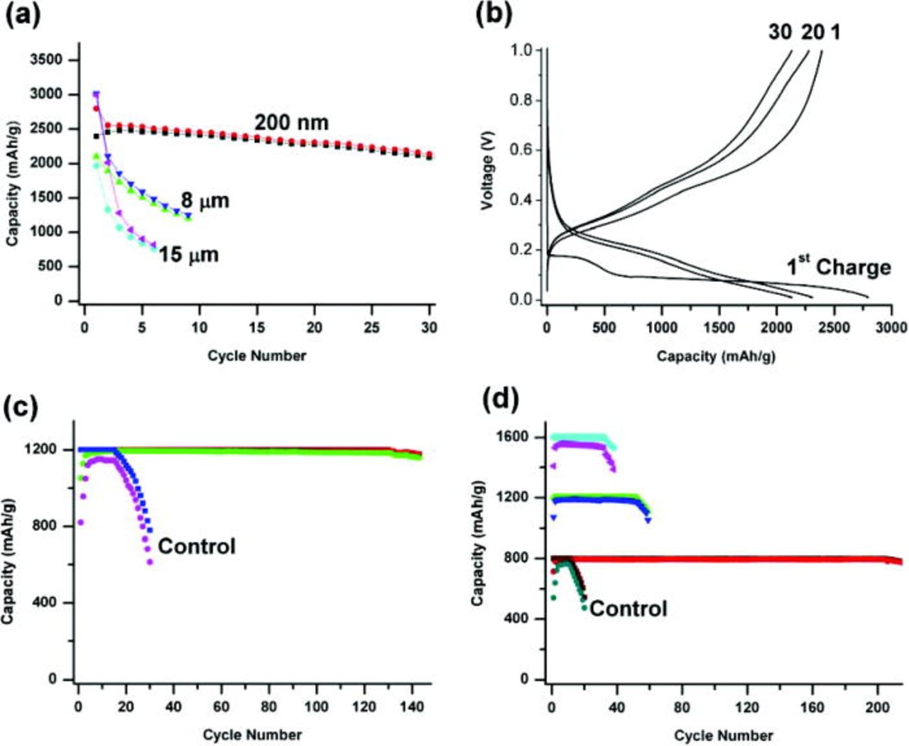
Figure 3. (Color online) (a) Charge and discharge cycling performance Si films prepared by inorganic glue method using three sizes of Si particles and cycled between 0.9–0.01 V. (b) The voltage profile of the 200 nm Si particle film in Fig. 3a. (c) The cycling performance of 200 nm Si particle film prepared by inorganic glue method and tested with CCC of 1200 mAh/g. The control study with CC of 1200 mAh/g is also shown in the graph. (d) The cycling performance of 8 μm Si particle films prepared by inorganic glue method and tested with CCC of 1600, 1200, and 800 mAh/g, respectively. The control study of 800 mAh/g is also show in the graph.
Previous studies have suggested that limiting the amount of Li+ intercalating with Si anode can greatly improve the cycling stability of Si.31 We used a constant charge capacity (CCC) cycling technique to limit the amount of Li+ inserted into Si particles during each cycle. In a real commercial lithium ion cell, the Li+ is stored in the cathode material and the amount of Li+ intercalating with anode is indeed limited. With an appropriate mass balancing of cathode and anode materials, the amount of Li+ intercalating with anode is precisely controlled just like our CCC technique.
We limited the amount of each Li+ charge to a value that is significantly smaller than the theoretical capacity of Si (∼4200 mAh/g), for example 1200 mAh/g. The lithiated Si anode was then discharged to a same upper voltage cutoff of 0.9 V. A constant current of C/10 was used for both charge and discharge. A lower voltage cutoff of 10 mV was also set to each charge, and during the beginning cycles the Si anode can be charged with the set capacity well before its voltage drops to 10 mV. However the charge voltage gets lower with cycle number. After many cycles the charge voltage will reach 10 mV cutoff before the Si anode can be charged with the set capacity thus decay of charge capacity will occur. Figure 3c shows the cycling performance of 200 nm Si particle anode using a CCC of 1200 mAh/g. The cell shows a 1st cycling Coulombic efficiency of 88%, and after several conditioning cycles the efficiency maintains a high value over 99%. The charge capacity of each cycle was set at a constant value of 1200 mAh/g. After 130 cycles, the charge voltage reached 10 mV and decay of charge capacity was observed.
To prove the effectiveness of our inorganic glue method, we also performed control studies using conventional slurry method, where SiNPs were mixed with carbon black and PVdF (8:1:1 wt) in NMP to form slurry and bladed onto copper foil current collector. Figure 3c also shows the control study of 200 nm Si using a CCC of 1200 mAh/g. The cell showed a rather poor Coulombic efficiency and bad cycling performance, which was a lot worse than our inorganic glue technique. To rule out the effect of carbon coating resulting from the carbonization of PAN, we also carried out control study using only carbonization process without deposition of a-Si as inorganic glue. SiNPs were mixed with 10% PAN in DMF to form slurry and bladed onto SS current collector. The PAN in the electrode film was carbonized at 700°C to produce carbon coated SiNPs. These carbon coated SiNPs also show much worse performance than our a-Si inorganic glue method.
We used the same CCC technique to test 8 μm Si particle electrodes. We tested different charge capacities of 1600, 1200, and 800 mAh/g, respectively. The cycling performance is shown in Fig. 3d. The 1600 mAh/g test shows a stable cycling for 42 cycles and the Coulombic efficiency ∼97%. The 1200 mAh/g test shows better performance than the 1600 mAh/g test, and the charge voltage reached 10 mV cutoff after 52 cycles, showing faster decay than 200 nm Si with the same charge capacity. This is expected because larger particle size is expected to show worse performance.
However when using 800 mAh/g charge capacity, the cell maintained a stable cycling for over 200 cycles. Its Coulombic efficiency maintained high values over 99% for more than 200 cycles. This long term stable cycling is likely due to the very little structural damage to Si particles at low capacity of 800 mAh/g. Therefore, the a-Si glue is working more effectively for 8 μm Si particles when the cells are charged smaller amount of Li+. As calculated by Dahn and co-workers,33 the volume expansion of Si upon charging is linearly dependent on the charged amount of Li+, meaning volume expansion of CCC of 800 mAh/g is only half of that of 1600 mAh/g. Also Si glue can maintain the electrical contact between Si particles for 800 mAh/g cycling. To our knowledge, no other research groups have ever shown a stable cycling of 8 μm Si over 200 cycles. Figure 3d also contains the control study of 8 μm Si using conventional slurry method with a CCC of 800 mAh/g. The performance of the control study is much worse than the cell made using our inorganic glue technique. The bad performance of the control studies prove that our a-Si inorganic glue method indeed greatly improve the cycling performance of Si particle anode.
Because micron-size Si particles can be easily produced using simple powder milling, the cost of production is expected to be many times lower than nano-structured Si. Our process consists of very simple steps such as slurry coating, carbonization and short time of silane CVD. Hence this method is very promising in commercial applications. Very cheap metallurgical grade Si may be used as the starting material. Millions of tons of metallurgical grade Si is produced each year in the steel or aluminum smelting industry and the price is only ∼$1000 per metric ton. Using metallurgical Si as starting material, the Si anode produced using our method will be multiple times cheaper than commercial graphite anode, which costs well over $10,000 per ton.
We also investigated our Si particle films after battery cycling. These Si electrodes were cycled with constant voltage cutoff between 0.9 and 0.01 V. Figure 4 shows the SEM images of Si films after cycling in comparison with those before cycling. Figures 4a and 4b are SEM images of 200 nm Si particle film before cycling and after 20 cycles, respectively. From the SEM images, the morphology of 200 nm Si particles did not change much after many cycles. Although Si particles experience repeated expansion and contraction over many cycles, the breaking or cracking of these nano-size Si particles were limited due to the already very small initial particle size. Figures 4c and 4d are SEM images of 8 μm Si particle film before and after cycling. In the SEM image before cycling (Fig. 4c) we see many big micron-size particles with an average diameter of ∼8 μm. However after just 2 cycles between 0.9–0.01 V, we found all the big particles (>4 μm) were broken down into smaller particles, which was caused by repeated Li+ insertion and extraction. From Fig. 4d, it is clear that the big mircron-size Si particles pulverized into smaller particles during Li+ cycling. The comparison of different sizes of Si particles before and after cycling provides direct evidence that larger particles are more prone to break or crack during Li+ insertion and extraction. This explains why smaller Si particles provide better battery cycling performance under the similar testing conditions.
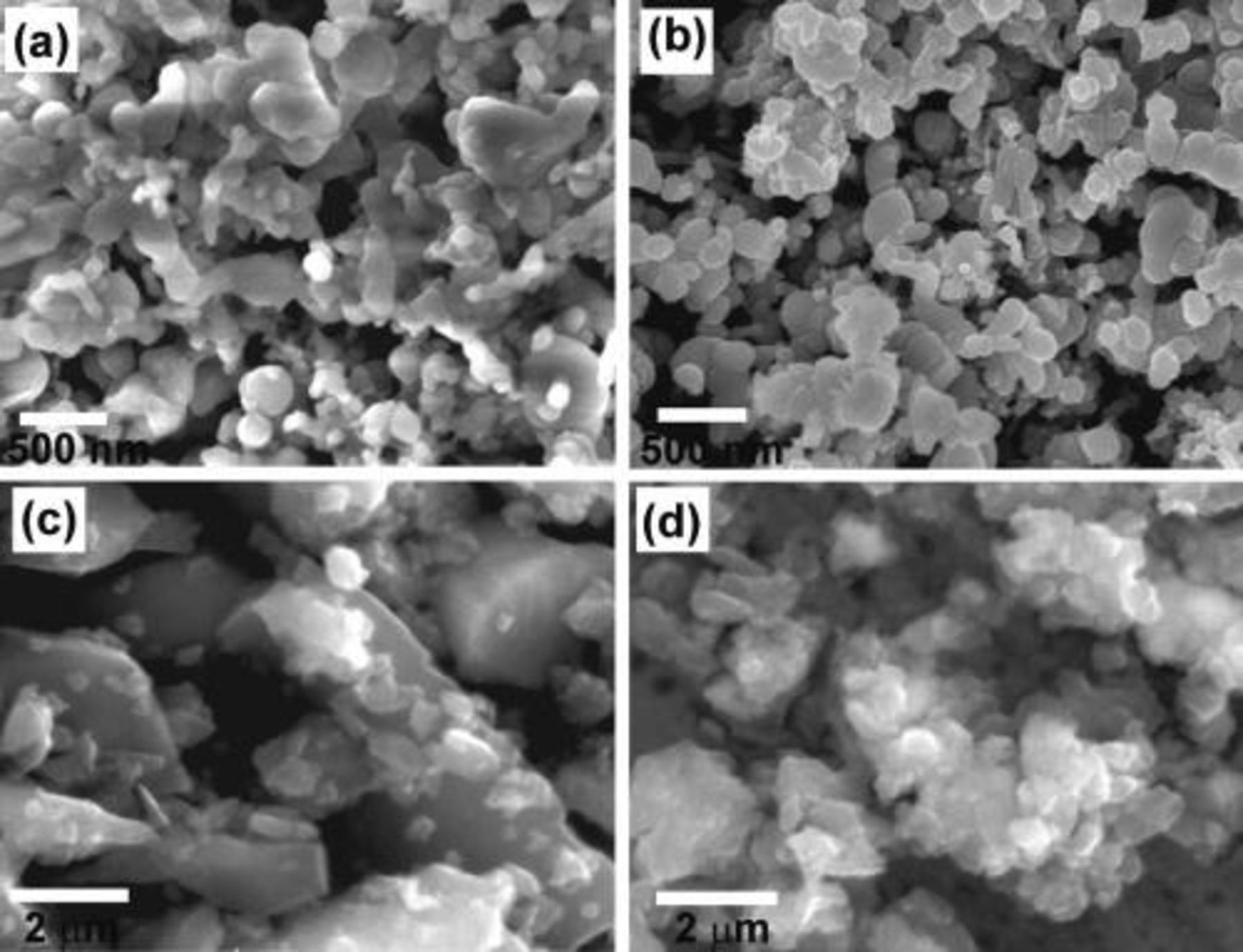
Figure 4. (a) and (b) SEM image of 200 nm Si particles before cycling and after 20 cycles between 0.9–0.01 V. The morphology of the Si nano-paritlces did not change much due to limited particle breaking. (c) and (d) SEM images of 8 μm Si particles before cycling and after 2 cycles between 0.9–0.01 V. The big Si micron-particles experienced severe pulverization after just 2 battery cycles.
Conclusions
In conclusion, we have invented a new method to prepare Si particle anode, where a-Si is deposited and acts as an inorganic glue to fuse all the particles together and bind them onto current collector. This inorganic glue can solve the issue of the loss of contact in silicon particle anode when prepared with conventional slurry method. We have used this method to successfully cycle various sizes of Si particles, both nano-particles and micron-particles. With a limited charge capacity of 1200 mAh/g, the prepared 200 nm Si particle anode showed stable cycling up to 130 cycles in a half cell test. With a limited charge capacity of 800 mAh/g, the 8 μm Si particles can be cycled over 200 cycles in half cell tests. The very cheap production of these Si particle anodes makes this inorganic glue method promising and competitive in lithium ion battery industry.
Acknowledgments
The work is partially supported by the Global Climate and Energy Project at Stanford, Office of Naval Research and King Abdullah University of Science and Technology (KAUST) under the Award KUS-I1-001-12 (to Y. C.).
Stanford University assisted in meeting the publication costs of this article.