Abstract
The past few decades have shown a rapid and continuous exhaustion of the available energy resources which may lead to serious energy global crises. Researchers have been focusing on developing new and renewable energy resources to meet the increasing fuel demand and reduce greenhouse gas emissions. A surge of research effort is also being directed towards replacing fossil fuel based vehicles with hybrid and electric alternatives. Energy storage is now seen as a critical element in future "smart grid and electric vehicle" applications. Electrochemical energy storage systems offer the best combination of efficiency, cost and flexibility, with redox flow battery systems currently leading the way in this aspect. In this work, a panoramic overview is presented for the various redox flow battery systems and their hybrid alternatives. Relevant published work is reported and critically discussed. A comprehensive study of the available technologies is conducted in terms of technical aspects as well as economic and environmental consequences. Some of the flow battery limitations and technical challenges are also discussed and a range of further research opportunities are presented. Of the flow battery technologies that have been investigated, the all-vanadium redox flow battery has received the most attention and has shown most promise in various pre-commercial to commercial stationary applications to date, while new developments in hybrid redox fuel cells are promising to lead the way for future applications in mechanically and electrically "refuelable" electric vehicles.
Export citation and abstract BibTeX RIS
While the need for batteries in RAPS (Remote Area Power Systems) and renewable energy storage applications has been understood for several decades, energy storage in general was largely ignored until recently due to the additional cost that would be introduced into any power generation system. With rapidly expanding implementation of wind energy generation in many countries around the world however, utilities are now looking for solutions to increasing problems of grid instability and poor reliability introduced by the renewable power sources on the grid. Governments around the world are now stressing the need for integrating storage into the so-called "Smart Grids" of the future.
Similarly, the rapid exhaustion of world oil reserves for global transportation needs is focussing world attention on the development of power sources for electric vehicles with lithium ion batteries receiving most of the international government and industry funding and attention. Lithium batteries offer very high energy densities needed for electric vehicle applications, but still suffer from high costs and safety concerns. Furthermore, long recharge times create inconvenience for users while fast charging options are likely to create enormous electricity demands that will put pressure on existing grid infrastructure. The same consideration will apply to all electrically rechargeable battery technologies that might be used in future electric vehicles, so electric power generation technologies that can be mechanically recharged would seem to be a desirable option.
A number of different energy storage technologies has been developed and a comparison of these technologies for different applications is presented in Table I. Each technology has some inherent limitations or disadvantages that make it practical or economical for only a limited range of applications. When combining performance requirements with cost, electrochemical systems are seen to be superior to the other forms of energy storage which are mainly mechanical in nature and therefore have relatively long response times compared to batteries and electrochemical capacitors.
Table I. Comparison of technicalities of different energy storage devices as against the redox flow battery (Refs. 1–6).
| Energy storage technology | Power rating(MW) | Discharge duration (h) | Response time | Efficiency(w/o power electronics) | Capital Cost($/kWh) | Cycle Cost ($/kWh) output | Life (y) | Cycle life at 80% depth of discharge | Maturity | Safety issues | Limitations |
|---|---|---|---|---|---|---|---|---|---|---|---|
| Pumped hydro | 10's MWs to GWs | > 8 | Very good | 70–85% | 80–200 | 0.001–0.02 | 30 | 20,000–50,000 | Commercial | Exclusion area | Special geological and geographic requirements |
| Superconducting magnet energy storage | 10's MWs | 0.25 | Good | 90–95% | 10,000 | 0.4–1.70 | 30 | 1000–10,000 | Commercial | Magnetic field | Needs a long loop to achieve commercially useful levels of storage |
| Compressed air energy storage | 10's MWs to GW | 0.1–15 | Very good | 60–79 | 50–110 | 0.03–0.06 (with gas) | 30 | 9,000–30,000 | Demonstration stage with limited commercial | Pressure vessels | Special geological and geographic requirements |
| Flywheel energy storage | 1–100 kWs | 0.1–1 | Slow | > 90% | 300–5,000 | 0.05–0.4 | 20 | > 20,000 | Commercial | Containment | Low energy density and efficiency |
| Super-capacitors | 5–100 kWs | 0.02–1 | Good | > 95% | 82,000 | 0.03–0.4 | low | 10,000–100,000 | Almost commercial | — | Low energy density, Unable to use the full energy spectrum and high self-discharge |
| Thermal energy storage | MW's to 100's MWs | 1–45 | Slow | 60% | $500/kW | 0.035–0.16 | 20 | 4000–10,000 | Commercial | High temperature | large investments required to build the initial infrastructure |
| Lead-acid batteries | kW to 10's MWs | 0.1–4 | Fast | 70–76% | 350–1500 | 0.40–1 | 5–10 | 200–1500 | Commercial in smaller systems. Several MW scale demonstrations | Potential for hydrogen explosions | Low to medium energy density. Poor deep discharge performance |
| Sodium sulphur batteries | 0.1–100's MWs | 1–10 | Fast | 85–90% | 300–950 | 0.09–0.5 | 5–10 | 210–4500 | Commercial More than 50 multi-kW to MW scale demonstrations | High temperature operation. Potential fires | Poor thermal cycling |
| Lithium ion batteries | KWs to 100's MWs | 0.1–1 | Fast | > 90% | 850–5,000 | 0.3–1 | 5–10 | 5,000–7,000 | Commercial in small scale appliances. Several MW-scale demonstrations | Potential fires and explosions (require advanced monitoring and control) | High cost |
| Flow batteries | kW–100's MW | 1–20 | High | 75–85% | 180–250 | 0.06–0.2 | > 10 | 5,000–14,000 | Almost commercial. More than 20 multi-kW to MW scale demonstrations. Several companies setting up commercial manufacture | Chemical handling and leakage | Low to medium energy density. Require more parts (such as pumps) compared with other types of batteries |
aDecreases with increasing energy to power ratio. Possible reduction by partial refurbishment. bUp to 270,000 cycles reported for All- Vanadium Redox Battery by Sumitomo Electric Industries, Japan.
Electrochemical energy storage systems provide direct conversion between chemical energy and electrical energy and are therefore particularly suited to the storage of electrical energy from all sources. Electrochemical storage technologies, also offer additional advantages compared with other types of energy storage systems, including:
- Can be sited anywhere, unlike pumped hydro or compressed air systems that have specific geographical or geological requirements.
- Are modular, so can be used in applications ranging from a few kWh to several MWh.
- Have millisecond response times so can be used simultaneously for both power quality and energy management applications.
- Have low environmental footprints so can be sited near residential areas.
For electric vehicles, only lithium ion technologies are currently regarded as being viable in terms of energy density and ease of operation, while the main battery technologies that are attracting the most attention for medium to large-scale grid connected energy storage applications are the sodium-sulfur, lithium ion and vanadium redox flow batteries.1, 7–10
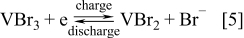
The redox flow battery (RFB) is a highly efficient energy storage technology that uses the redox states of various soluble species for charge/discharge purposes.11 Putting it simply, the redox flow battery consists of two reservoirs for storing discharged/charged electrolytes, an energy converting system (a cell stack) comprising a number of cells connected in series or parallel, pumps for pumping the electrolytes through the power converting system and connection to the energy generating/consuming device.11, 12 A simple schematic of an RFB is shown in Fig. 1.10, 13, 14
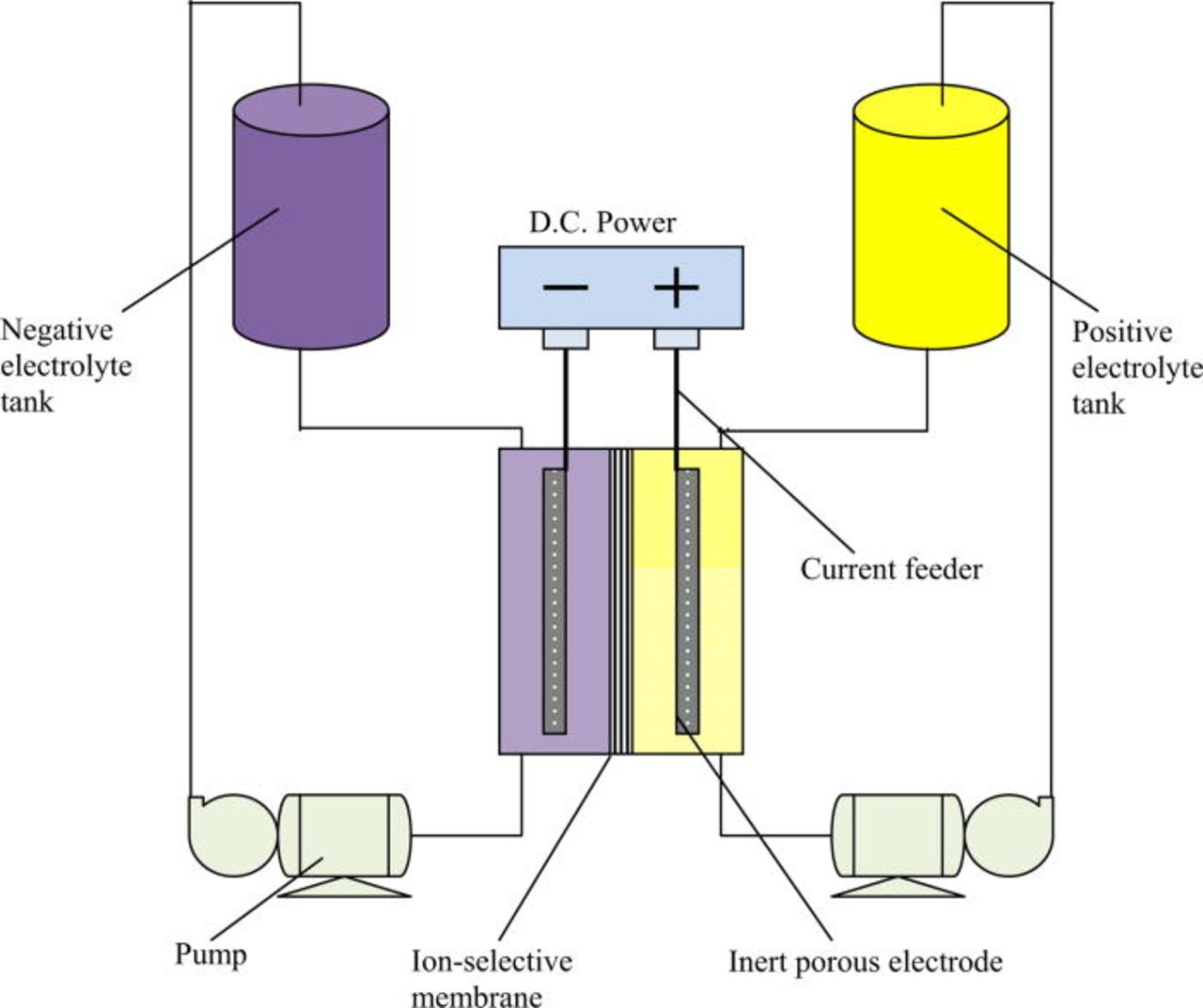
Figure 1. (Color online) Redox Flow Battery Schematic.
The electrolytes in each half-cell store the energy chemically as solutions and are pumped around the cell stack where electron transfer reactions take place at inert electrodes. Typically each redox cell employs ion exchange membranes to separate the two half-cell electrolytes and flow-through/flow-by electrodes. The electrolyte solutions contain electro-active species and a high concentration of a supporting electrolyte to minimize the solution resistance.11 Each half-cell electrolyte is stored in a separate storage tank. There are two redox species with different electrochemical potentials involved. An external source of power is applied at the terminals and as the two half-cell solutions are pumped through the cell stack, the discharged form of each redox couple is converted into the corresponding charged form. When a load is connected across the terminals of the charged or partially charged cell or battery, electrons flow between the redox species and chemical energy is converted to electrical energy.10 Energy is therefore stored in the solutions and the capacity of the system is determined by the concentration of the active redox couple species and the solution volume. On the other hand, the power rating of the system is determined by the number of cells in the cell stack and the electrode area.
While the redox flow cell concept has been around for close to 40 years with several systems evaluated by various groups around the world, only the vanadium redox flow battery invented by Skyllas-Kazacos and co-workers at the University of New South Wales, Australia10, 14–63 has to date, reached commercial fruition.64–67 Earlier reviews of redox flow batteries have described a range of chemistries and cell technologies that have been researched and developed11, 68 and these are also reviewed in this paper. Since these reviews were published, however, a number of new developments have taken place and these warrant further assessment. Furthermore, certain redox flow batteries and redox couple systems were omitted from earlier reviews (including the all-chromium redox species and the iron/titanium system). The focus of the review by Ponce de Leon and co-workers68 was towards system operating conditions and charge/discharge characteristics of selected systems instead of an overall comparison of various technologies and their commercial potential. The present paper attempts to discuss the technology in general and can be considered to be an extension to the original historical review of Bartolozzi,11 while also providing a status report on commercial development and large-scale field testing, in addition to a detailed assessment of the technical challenges and future research opportunities in the field.
Some of the systems that have been considered here are not strictly redox flow batteries because their half-cell reactions involve the deposition of solid species.69 These systems are also known as "hybrid" redox flow batteries. They are included here because of their similar design and operation to the redox flow battery and come under the general heading of "flow batteries". Such hybrid systems include those that involve the deposition of a metal at the negative electrode during charging (e.g. the zinc-bromine (Zn/Br) and zinc-chlorine (Zn/Cl) batteries) and the hybrid redox fuel cells, the first of which utilises a fuel and oxidant to chemically regenerate the two redox couple solutions in-situ.
The chemically regenerative redox fuel cell incorporates a redox couple electrolyte as the mediator in the charge-discharge reactions of a hydrogen-oxygen fuel cell as a means of eliminating the need for expensive noble metal catalysts for hydrogen oxidation and oxygen reduction. Chemically regenerative fuel cells were originally investigated for electric vehicle applications, but low power densities and slow reaction kinetics restricted their application. A further extension of this concept is the hybrid redox fuel cell concept that eliminates the positive half-cell electrolyte and replaces it with a gas diffusion air or oxygen electrode, effectively doubling the energy density compared with the conventional redox flow cell. These variations to the flow cell concept have not been discussed in previous reviews and are included here for completeness.
Redox Flow Battery Technology
Redox flow batteries are sometimes referred to as electrochemically regenerative fuel cells since they involve the supply of an externally stored fuel and oxidant in the form of two soluble redox couples that produce electrical energy when they undergo oxidation and reduction reactions at inert electrodes that are separated by an ion exchange membrane in an electrochemical cell. Redox flow batteries are distinguished from fuel cells however, by the fact that the electrochemical reactions involved are reversible, i.e. they are generally of the secondary battery type and so they can be recharged without replacing the electroactive material.10 Although fuel cells have previously been considered as possible electrochemical storage devices, their very low round trip efficiencies (less that 40% compared with 70–85% for redox flow batteries), has ruled them out as near term contenders for large-scale energy storage applications. Although still under consideration for electric vehicle applications in the longer term, technical solutions to the generation, storage and transportation of hydrogen are still needed for their practical implementation.
The redox flow cell concept was investigated in Japan as far back as 1971.70 Since then, the redox flow battery has seen significant developments leading to many small to medium-scale field tests and demonstrations in the 1980s and 90s, mainly in Japan under various NEDO projects.11, 68, 71–73 As fully soluble redox couples and inert electrodes are used, undesirable electrode processes are eliminated (especially structural changes of the electrode) in comparison to secondary battery systems.74 The system energy storage capacity is determined by the concentrations of the reactants and the size of the storage tanks, while the system power is determined by the number of individual cells within a battery stack and their electrode area.22, 75 As a result it is possible to independently optimize the flow cell's storage capacity and the power output.10 This feature makes redox flow batteries unique in their ability to provide the specific power and energy requirement for each application. Storage capacity can be increased by simply adding more electrolytes, so the incremental cost of each additional energy storage capacity unit is lower than other types of battery technologies. The cost per kWh of the system therefore decreases substantially with increasing storage capacity, making the flow battery particularly attractive for applications requiring storage times in excess of 4–6 h.10
Other attractive features of redox flow batteries (as opposed to other electrochemical energy storage systems) are (Refs. 76, 77):
- Simple electrode reactions;
- Favourable exchange currents (for some redox couples);
- Compared with sodium sulphur batteries, no high temperatures are required;
- No morphological changes that limit cycle life and depth of discharge.
The only moving parts are the pumps, which need replacement every 5–7 years. One drawback of flow batteries, at least compared to other batteries, is their size. While the power cells or stacks are not extremely large, the electrolyte storage tanks can be quite bulky78, 79 and this could be a disadvantage where space is limited as in commercial buildings and in cars. Another concern is due to the toxicity of some of the electrolytes employed. For these reasons, the technology is more attractive as a stationary storage device for load-levelling and stand-alone applications,80–82 although further progress with the hybrid redox fuel cells is expected to lead to significant improvements in energy density that will open up applications in electric vehicles. Such systems would be of particular interest in electric cars since they would allow rapid refuelling by solution exchange at special refuelling stations, eliminating the slow charging times associated with conventional battery technologies while also allowing recharging of the spent solutions during periods of low demand.22 Recent work in this area will be reviewed and discussed later.
Early technology and the iron-chromium redox flow battery
Many potential redox couples were screened by NASA (Refs. 22, 83) since the first proposal of the redox flow cell concept by Thaller.77 Out of several candidates for application as redox couples in the electrochemical energy storage system, the iron/chromium couple was selected and developed.84 The main criteria used by NASA in the selection of iron and chromium were cost and availability. In general, the system consisted of acidified solutions of chromium [Cr(III)/Cr(II)] and iron [Fe(III)/Fe(II)], initially as unmixed reactants22, 83 and later as premixed solutions in order to address the issue of cross mixing of the electrolytes across the membrane.85
In premixed solutions both the positive and negative electrolytes contained iron and chromium species as soluble salts in aqueous solutions of hydrochloric acid. The cell reactions as well as the main technical features of the iron/chromium system are summarized in Table II, while an historical overview of its development is given in Table III.
Table II. Early Redox Flow Battery Technology developed by NASA and Japanese researchers.
| No. | Redox system | Electrolyte condition | Charge/discharge reaction at electrodes | OCP (V) | Charge/discharge current density (mA/cm2) | Cell type | Electrode and membrane materials used | Charge/discharge Efficiency(%) | References |
|---|---|---|---|---|---|---|---|---|---|
| 1 | Iron-chromium | 1 M CrCl3 and FeCl2 in 2 M HCl in the negative and positive sides of the cell, respectively | Positive electrode: Fe2+ → Fe3+ + e− Negative electrode: Cr3++e− → Cr2+ | 1.18 | 21.5 | Flow-cell | 1/8 in. carbon felt electrodes with traces of lead (100–200 µg cm−2) and gold (12.5 µg cm−2) deposited on the electrode used for chromium along with ion exchange membrane (Ionics Inc. series CD1L) | 95 (coulombic) | 68 |
| 2 | Iron-titanium | Positive half-cell: 1 M FeCl3 + 3 M HC1 and Negative half-cell: 1M TiC13 + 3.5 M HC1 | Positive electrode: Fe2+ → Fe3+ + e− Negative electrode: Ti4+ + e− → Ti3+ | 1.19 | 14 | Flow cell | Graphite foil electrodes compared with platinized platinum foil and a titanium-base chlorine anode. Anion-permeable membrane Ionac MA-3745. | 44–50 (overall) | 86–89 |
| 3 | [Ru(bpy)3] (BF4)2 | 0.02 M [Ru(bpy)3](BF4)2 as the active species and 0.1 M TEABF4 as the background electrolyte in acetonitrile | Positive electrode: [Ru(bpy)3]2+ ↔ [Ru(bpy)3]3+ + e−Negative electrode: [Ru(bpy)3]2+ + e−↔ [Ru(bpy)3]+ | 2.6 | 3 V–50% SOC (charge) 5 (discharge) | Flow cell | Anion exchange membrane (Neocepta ACH-45T, Tokuyama Soda) Carbon fibre cloth electrodes | 18 (overall) | 90 |
Table III. Historical evolution of the iron/chromium redox flow cell.
| Redox system | Year | Electrode materials | Electrolyte | Membrane | Battery type | Comment | References |
|---|---|---|---|---|---|---|---|
| Iron-chromium | 1985 | Carbon felt with traces of gold and lead for chromium half reaction and carbon felt for iron half reaction. Area of electrode 14.5 cm2 | 1 M CrCl3 and FeCl2 in 2 M HCl in the negative and positive sides of the cell, respectively | Ion exchange membrane (Ionics Inc. series CD1L) | 1 kW prototype flow battery system demonstrated in 1980 | A higher polarization during the charging cycle was observed in comparison to the discharge cycle that resulted in lower energy storage efficiency | 91 |
| 1988 | 2 carbon fiber electrodes of 10 cm2 geometrical area | 1 M chromic chloride in the negative half-cell and 1 M of both ferric and ferrous chloride, both in 4N hydrochloric acid in the positive side | Cation Exchange Membrane | Flow cell | The addition of boron into the carbon fibers help to achieve high energy efficiency. Energy density of 15 Wh/kg obtained | 92 | |
| 1992 | Pre-treated RVC-4000 (Le Carbonne Lorraine) carbon felt. Electrodes were treated by: (i) immersing in methanol for 5 min;(ii) immersing in H2O2 for 48 h and washing with water until pH = 7 | 2.3 M HCl + 1.25 M FeCl2 + 1.25 M CrCl3 in both half-cells | Nafion 117 | Flow type operating in bipolar mode | Optimization studies on electrolyte composition, temperature and membrane type only. Battery operated at 44°C and 40 mA/cm2 current density | 80 | |
| 2002 | Thermally treated graphite felt | Negative half-cell: 0.1 M FeCl2 + 1 M HCl Positive half-cell: 0.1 M CrCl3 + 1 M HCl | Cation exchange membrane (Nafion 450, Du Pont) | H-type glass cell with no flow | Low open circuit potential of 1.84 in comparison to EDTA complex and energy output of 1.7 × 10⁻² Wh | 93 |
Scale-up studies of the iron/chromium RFB were conducted by a number of workers81, 94–97 but the system was not commercially developed at the time due to problems of low energy density for the mixed electrolyte cell, membrane fouling and the slow reaction of chromium redox species on most electrode surfaces that required expensive noble metal catalysts.93
Thaller77 discussed the possibility of employing a soluble Fe(III)/Fe(II) – Ti(IV)/Ti(III) redox system in aqueous hydrochloric acid solution for use in a redox flow battery. Preliminary size and cost estimates for bulk energy storage using such redox couples were also evaluated.82 The overall cost of constructing such a system compared well with that of competing energy storage systems and savings in transmission costs were also achievable. However, the system was never commercialized due to the slow kinetics of the negative electrode reaction. The technical features of the iron-titanium system are summarized in Table II.98 The charge-discharge reactions are as follows86, 87

The open-circuit potential (OCP) of this system was 1.19 V whilst operating at room temperature, with an energy efficiency varying between 44 and 50%.88, 89 The energy density of the system was reported to be 13.25 Wh/kg. These values were obtained for cells using lead as an electro-catalyst to enhance the kinetics of the titanium redox couple [Ti(IV)/Ti(III)] at a graphite negative electrode. The slow kinetics of this couple was also confirmed independently by other researchers.99 Other workers87 found that the kinetics of the titanium couple could be enhanced by impregnating the graphite negative electrode of their cell with palladium, but the cost of this would be prohibitive. Further investigations using flow cells have yet to be carried out to compare their performance with the original prototype system developed by NASA.86 As with the Fe-Cr system, the low energy density and expensive electrode catalysts needed for the Fe-Ti cell make this system less attractive that other prospective redox couple combinations.
Organometallic redox species in acetonitrile solvent were proposed for redox flow batteries by Japanese researchers in the late-1980s.90, 100 These species included tris(2,2'-bipyridine) ruthenium(II) tetrafluoroborate and ruthenium(III) acetylacetonate. The former species was investigated in a redox flow cell, yielding an overall energy efficiency of 18% as shown in Table II.90 The cell charge-discharge reactions are also given in Table II. Given the high cost of ruthenium, such a system is unlikely to become practical however and there is little justification for further research.
The iron-chlorine and tin-chlorine batteries were patented in 1985.101 These cells employed the Cl−/Cl2 couple in the positive half-cell and the Fe(II)/Fe(III) and Sn(II)/Sn(IV) couples in the negative half-cells respectively. Nozaki also reported studies of a secondary redox-flow battery (hybrid) with chromium and halogen couples giving a voltage of 1.2 V.102 In addition, an iron-chlorine redox system with graphite cloth gas electrodes was studied by Kondo (National Chemical Laboratory, Tsukuba, Japan) (Ref. 103) while electrolytes for redox-flow batteries, prepared from ferrochromium ores, were patented by Wakabayashi (Chiyoda Chemical Engineering Co. Ltd., Japan) (Ref. 104). However, none of these redox systems were considered for scale-up due to the poor electrochemical reversibility of the respective redox couples in solution.
All-vanadium redox flow battery
Research on the all-vanadium redox flow battery (VRB) first began in 1984 at the University of New South Wales (UNSW), Australia under funding from the National Energy Development and Demonstration Council.14, 15 The VRB was first proposed by Skylllas-Kazacos and co-workers to overcome the inherent problem of cross contamination by diffusion of different redox ions across the membrane. By employing the same element in both half-cells, any cross contamination would be avoided, allowing the electrolyte life to be extended indefinitely.10, 14
The VRB employs the V(II)/V(III) and V(IV)/V(V) couples in the negative and positive half-cells respectively with the following charge-discharge reactions:
Positive electrode reaction
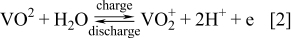
Negative electrode reaction
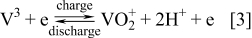
The open circuit potential (OCP) of the fully charged cell is about 1.6 V when the negative and positive half-cell electrolytes comprise 2 M V(II) and 2 M V(V) respectively. The energy density for 2 M vanadium electrolytes is approximately 25 Wh/g.50 The system has been successfully operated over a temperature range of 10–40°C.27, 44, 49
Development of the vanadium redox flow battery began at the University of New South Wales in Australia where it was taken from the initial concept stage in 1984 through the development and demonstration of several 1–4 kW prototypes in stationary and electric vehicle applications during the late 1980s and 1990s.14–63 As part of the 25 year vanadium flow battery research and development program, a wide range of research projects were undertaken, these spanning the areas of electrode screening and characterization,15–23 electrocatalysis and carbon electrode modification and characterization,24–26 electrolyte optimization and characterization27–31 membrane screening, characterization and modification,32–43 conducting plastic electrode formulation and evaluation,44–48 additives for stabilisation of supersaturated vanadium solutions,49, 50 chemical regeneration,51 state-of-charge monitoring,52, 53 vanadium salt dissolution and electrolyte production,54, 55 control system development,52, 56 stack design and optimization57–61 gelled electrolytes62 and vanadium/oxygen redox fuel cells,63
A brief description of the all-vanadium redox battery's general properties and features is presented in Table IV, while its historical development is given in Table V.
Table IV. General properties and features of the all-vanadium and other vanadium based redox flow battery technologies.
| No. | Redox system | Electrolyte composition | Charge/discharge reaction at electrodes | OCP (V) at 100% SOC | Charge/discharge current density(mA/cm2) | Cell type | Electrode and membrane materials used | Charge/discharge Efficiency (%) | References |
|---|---|---|---|---|---|---|---|---|---|
| 1 | All-vanadium | 1.6–2 M vanadium sulphate in sulphuric acid in both half-cells | Negative electrode: V3+ +e− → V2+Positive electrode: VO2+ +H2O − e− → VO2+ +2H+ | 1.6 | 10–130 | 1–5 kW bi-polar stacks | Graphite felt electrodes heat bonded on carbon-filled polyethylene conducting plastic bipolar substrates. Modified low-cost perfluorinated cation exchange membrane. | 80% at 40 mA/cm2 (overall) | 10, 16, 79 |
| All-vanadium | 1.5 M vanadium sulphate + 2 M sulphuric acid at 22°C in both half-cells | As above | 1.6 | 40 | Flow cell | Sandwich-type sulfonated poly(ether ether ketone) (SPEEK)/tungstophosphoric acid (TPA)/polypropylene (PP) composite. | 83% overall | 105, 106 | |
| 2 | Vanadium-bromine | 1–3 M vanadium bromide in 7–9 M HBr plus 1.5–2 M HCl in both half-cells | Positive electrode: 2VBr3 + 2e − → 2VBr2 + 2Br−Negative electrode: 2Br− + Cl− → ClBr2 − + 2e– | 1.4 | 20 | Flow cell | Nafion 112 membrane. Electrodes: carbon or graphite felt bonded onto conductive plastic sheets | 74 (overall) | 79, 107 |
| 3 | Magnesium-vanadium | Positive half-cell: 0.3M Mn(II)/Mn(III) in sulfuric acid). Negative half-cell: V(III)/V(II) in 5 M sulphuric acid | Positive electrode: Mn(II) → Mn(III) + e−Negative electrode: V(III) + e− → V(II) | 1.66 | 20 | Flow cell | Polyacrylonitrile (PAN) based carbon felt or spectral pure graphite electrodes with Nafion 117 (DuPont, USA) membrane | 63 (overall) | 108 |
| 4 | Vanadium-cerium | Positive half-cell: 600 ml of 0.5 M Ce(III) in 1 M H2SO4. Negative half-cell: 600 ml of 0.5 M V(III) in 1 M H2SO4 | Positive electrode: Ce3+ → Ce4+ + e−.Negative electrode: V3+ + e− → V2+ | 1.5 | 22 | Cylindrical flow cell | Porous Vycor glass with pore size of around 45 Å as membrane. Carbon fibers of 10 μm diameter as negative electrode filled inside cylindrical membrane. Four bundles of the carbon fibers arranged evenly around the outside of the membrane as positive electrode. | 90 (coulombic) | 109–111 |
| 5 | Vanadium-glyoxal(O2) | Positive half-cell: 50 ml glyoxal–HCl solution of different concentration. Negative half-cell: 1–2 M V(III) + 3 M H2SO4 solution | Positive electrode: [OC]RE + H2O → [OC]OX + 2H+ + 2e− (where [OC]RE represents the organic reductive raw materials and [OC]OX represents the electro-oxidized organic products).Negative Electrode: V3+ + e → V2+ | 1.2 | 20 | Flow cell | The gas diffusion layer and a PTFE sheet (Nitto Denko, 50 mm thick) were placed on each side of a Nafion115 cation exchange membrane and then hot-pressed at 150°C to form a gas diffusion layer hot-pressed separator for the BRFB. Graphite plates and porous graphite felts served as current collectors and electrodes, respectively. | 66 (coulombic) | 112 |
| 6 | Vanadium-cystine (O2) | Positive half-cell: 0.1 M cystine dissolved in HBr aqueous solution of different concentrations. Negative half-cell: 50 ml of 1 M V(III) + 3M H2SO4 | Positive electrode: RSSR + Br2 + 6H2O → 2RSO3H + 10HBr (where RSSR = L-cystine and RSO3H = L-cysteic acid) Negative electrode: V3+ + e− → V2+ | 1.315 | 20 | Flow cell | GDL hot pressed separator as membrane. It employed 2.5 mm thick graphite felts (dimension: 25 × 20 mm) contacted against graphite plates that served as current collectors. | 58 (overall) | 113 |
| 7 | Vanadium-polyhalide | Positive half-cell: 1M NaBr in 1.5M HCl. Negative half-cell: 1M VCl3 in 1.5M HCl | Positive electrode: Br− + 2Cl− → BrCl2 − + 2e− Negative electrode: VCl3 + e− →VCl2 + Cl | 1.3 | 20 | Flow cell | Glassy carbon sheets as the current-collectors and graphite felt as the electrode material in both the half-cells. Nafion 112 membrane. | 83 (coulombic) 80 (voltaic) | 107 |
| 8 | Vanadium acetylacetonate | 0.01 M V(acac)3/0.5 M TEABF4/CH3CNin both half-cells | Positive electrode:V(III)(acac)3 → [V(IV)(acac)3]+ + e−. Negative electrode: V(III)(acac)3 + e− → [V(II)(acac)3]− | 2.2 | 2.2 (charge) 0.2 (discharge) | Stationary H-type cell | Graphite electrodes and AMI-7001 anion-exchange membrane. | 47 (coulombic) | 114 |
| 9 | Vanadium/air system | Positive half-cell: H2O/O2. Negative half-cell: 2M V2+/V3+ solution in 3M H2SO4 | Positive electrode: 2H2O → 4H+ + O2 + 4e−. Negative Electrode: V3+ + e → V2+ | ≈ 1 V for 8 h | 24 A/m2 | flow cell with oxygen gas diffusion electrode | For charging, the air side of the cell contained a membrane-electrode-assembly (MEA) that was made from a catalyst coated Ti-mesh electrode of 100 mm thickness. For discharging, the air side of the cell contained a MEA of a catalyst coated sintered porous Ti-electrode of 1.2 mm thickness. Membrane was Nafion 117. | 45.7 (overall) | 115, 116 |
Table V. Historical Overview of the All-Vanadium Redox Flow Battery.
| Year | Electrode materials | Electrolyte | Membrane | Battery type | Comment | References |
|---|---|---|---|---|---|---|
| 1986 | Graphite plates | The negative and positive half-cell electrolytes consisted of 0.1 M V (III) and 0.1 M V(IV) in 2 M H2SO4 respectively | Sulphonated polyethylene anion selective material. | Stationary H-type cell and laboratory-scale flow cell | Charged and discharged at 3 mA/cm2 and gave good performance. Graphite plates not suitable under high oxidizing conditions | 19 |
| 1987 | Graphite negative and iridium oxide coated titanium dimensionally stable anodes as positive electrodes | 0.5–2 M vanadium solution | Sulfonated polyethylene cation selective and polystyrene sulphonic acid cation selective membranes evaluated | Single redox flow cell | Dimensionally stable anode material showed best stability during short term cycling compared with graphite plates and other types of electrodes | 20 |
| Graphite feltnegative electrodes | 1.5 M vanadium solution prepared from 0.1 to 2M vanadyl sulfate (VOSO4) in 2M H2SO4 | Polystyrene sulfonic acid cation selective membrane | Single redox flow cell | Coulombic and voltage efficiency of 90 and 81%, respectively, over 10–90% state of charge | 16 | |
| 1989 | 6 mm thick felt electrodes of 132 cm2 surface area bonded to a graphite impregnated polyethylene plate | 2 M vanadium sulphate in 2 M H2SO4 | Polystyrene sulfonic acid membrane | Single redox flow cell | 87% overall energy efficiency obtained using these electrodes | 44 |
| 1991 | Graphite felt heat bonded onto conducting plastic bipolar electrodes | 1.5–2 M Vanadium sulphate in H2SO4 | Selemion CMV | 1 kW stack incorporating 10 cells with 1500 cm2 electrode area | 90% overall energy efficiency at 30 Amp charge-discharge currents. Maximum continuous power of 1.58 kW at 120 A | 57 |
| 1991 | Modified graphite fibre electrodes by surface ion exchange of Pt4+, Pd2+, Au4+, Mn2+, Te4+,In3+ and Ir3+ ions | Cyclic voltametric studies in 1–2 M VOSO4 in H2SO4 | N/A | Small electrochemical cell | Electrode modified by Ir3+ exhibited the best electrochemical behaviour for the various vanadium redox species. | 24 |
| 1992 | Thermally treated graphite felt electrodes in air atmosphere at 400°C for 30 h | 2 M V(III)/2 M H2SO4 solution as the negative electrolyte, and 2 M V(IV)/3 M H2SO4 solution as the positive electrolyte | Not specified | Single redox flow cell | Over 88% energy efficiency. Studied active surface functional groups on carbon and proposed methods to increase active sites for improved electrochemical activity | 25 |
| Chemically modified graphite felt electrodes by boiling in concentrated sulphuric acid for 5 h | 2 M V(III)/2 M H2SO4 solution as the negative electrolyte, and 2 M V(IV)/3 M H2SO4 solution as the positive electrolyte | Not specified | Single redox flow cell | Surface modification of graphite felt was done with concentrated sulphuric acid to increase concentration of active sites for electron transfer reactions. 91% efficiency reported | 26 | |
| 1992 | Graphite felt on graphite plate current collectors | 2 M vanadium sulphate in 3 M H2SO4 | Daramic based composite ion exchange membranes | Single redox flow cell | Preparation of composite membrane using low cost microporous separator. Coulombic, voltage and energy efficiencies of 95, 85 and 83%, respectively. More than 700 cycles (4000 h), without any appreciable drop in performance | 33, 34 |
| 1997 | Two layer, porous electrodes comprising high surface area porous carbon fibre electrode layer at the septum side and a porous low surface carbon fiber at the bipolar plate side | Vanadium in sulphuric acid | Not specified | Flow cell with electrode dimensions 45 cm x 80 cm used in 40–50 kW stacks | Grooves in porous graphite used to reduce pressure drop. 94.1% current efficiency, 82.5% overall efficiency, 87.6% voltage efficiency, 1.07 Ω.cm2 cell resistance and 0.51 kg/cm2 pressure loss when the electrolytic solution passed through the multilayer porous electrode. Electrode design used in 40–50 kW modules for 200 kW/800 kWh VRB load-levelling system at Kashima-Kita Electric Power Station | 117, 78 |
| 1997 | Carbon fibre felt electrodes | 2 M VOSO4 in 4 M H2SO4 solution | Cross linked anion exchange membrane by accelerated electron radiation | Single redox flow cell | Overall energy efficiency of 80% reported | 118 |
| 2002 | Carbon-on-gold | Electrolysis of a 1 M solution of VOSO4 in 25% H2SO4 | No membrane | Membrane-less vanadium redox fuel cell | A maximum of 10% cell efficiency was achieved | 119 |
| 2006 | Chemically treated carbon felt | 1.5M VOSO4 + 3M H2SO4 | Nafion (Du Pont) | 14-cell 1 kW class VRB cell | 10 x 1 kW stacks integrated into 10 kW battery. Energy efficiency of more than 80%, at an average output power of 10.05 kW | 120 |
| 2007 | Carbon felt | 2 M V(IV) in 2.5 M H2SO4 catholyte and 2 M V(III) in 2.5 M H2SO4 anolyte | Nafion/SiO2 hybrid membrane was prepared via in situ sol–gel method | Single redox flow cell | 1 M active species concentration, 20 mA cm−2 current density gave an energy efficiency of nearly 80% | 121 |
| 2008 | Graphite felt | 2 M V(IV) in 2.5 M H2SO4 catholyte and 2 M V(III) in 2.5 M H2SO4 anolyte | Nafion–[PDDA-PSS]n membrane (n = the number of multilayers) | Single redox flow cell | Maximum CE of 97.6% and EE of 83.9% achieved at charge–discharge current densities of 80 mA cm−2 and 20 mA cm−2, respectively | 122 |
| Graphite felt (electrode), an adhesive conducting layer (ACL) and a flexible graphite plate (bipolar plate) | 1.5M VOSO4 + 3M H2SO4 | Nafion 117 membrane | VRB Single flow cell | Energy efficiency of 81% at a charge/discharge current density of 40 mA cm−2 | 123 | |
| 2009 | Graphite felt. | 1.5M VOSO4 + 3M H2SO4 | Nafion 115 membrane | VRB Single flow cell | A simple mathematical model approximates reaction conditions very well. At current density of 40 mA cm−2 a cell potential of 1.65 V is achieved at 90% state of charge | 105 |
| Two pieces of carbon felt were used as electrodes, serpentine flow fields graphite as polar plates | 2.0 M V3+/V4+ + 2.5 M H2SO4 solutions | Nafion/ORMOSIL (novel Nafion/organically modified silicate) hybrid membrane | VRB Single flow cell | Energy efficiency is 87.5% with novel membrane in comparison to traditional Nafion (74%) and Nafion/SiO2 hybrid membrane (80%) | 124 | |
| Two pieces of carbon felt used as electrodes, serpentine flow fields graphite as polar plates | 1 M vanadium solution in 2.5 M sulphuric acid | Nafion/organic silica modified TiO2 composite membrane prepared by in situ sol–gel method | VRB Single flow cell | Novel membrane resulted in energy efficiency of 78% in comparison to 77% for normal Nafion membrane in the all-vanadium RFB (SOC of 75%). This was constant over a cycle life nearing 100. | 125 | |
| 2010 | Carbon felt served as electrodes, and conductive plastic plates served as current collectors | 1.5 M VOSO4 in 2.0 M H2SO4 | Sandwich-type sulfonated poly(ether ether ketone) (SPEEK)/tungstophosphoric acid (TPA)/polypropylene (PP) composite membrane | VRB Single flow cell | 82.6% energy efficiency in comparison to the employment of a Nafion 212 membrane for more than 80 charge/discharge cycles at 35.7 mA cm−2 | 106 |
| Nitrogen-doped mesoporous carbon | 3.0 M H2SO4 + 1.0 M VOSO4 solution | No membrane for CV | Cyclic voltammetry and impedance tests only | The reversibility of the redox couple is greatly improved on N-MPC (0.61 V for N-MPC vs. 0.34 V for graphite), which is expected to increase the energy storage efficiency of redox flow batteries | 125 | |
| Thermally treated graphite felt electrodes | 0.02 M VOSO4 in 1 M H2SO4 solution | Undivided reactor/membrane less | Single pass flow cell | 13.4% energy efficiency, which is higher than membrane less vanadium redox fuel cell (Ref. 119) | 13 |
Although vanadium redox couples had been previously considered for redox cell applications, they were believed to be impractical due to the very low solubility of V(V) compounds which would have restricted the concentration of the vanadium electrolyte to less than 0.5 moles/l, this being much too low for practical use. The UNSW breakthrough came when it was discovered that highly concentrated V(V) solutions could be prepared in sulphuric acid by the electrochemical oxidation of V(IV). By oxidising a 2 M vanadyl sulphate solution, it was possible to prepare a highly concentrated 2 M V(V) solution which did not precipitate over a reasonable temperature range.14 This meant that reasonable vanadium solution concentrations could be achieved for a practical flow battery system.
A second major challenge that had to be addressed during the early development was the high cost of vanadyl suphate originally used in the electrolyte production. Lower cost vanadium oxide materials could not be used due to their very low solubilities. A further milestone in the early UNSW research program therefore, was the development of a low cost process for producing vanadium electrolyte from the vanadium oxide raw material. The low solubility of the oxides meant that simple dissolution could not be used in electrolyte production, so electrolytic and chemical reductive dissolution processes were developed,54 allowing lower cost raw materials to be employed and thereby making the VRB economically viable.
The initial system developed at UNSW had an overall energy efficiency of 71% but with further enhancements in materials and cell design, an overall energy efficiency of up to 90% was achieved with a 1 kW VRB stack in 1991.57 These enhancements included the identification of high performance membranes with low electrical resistance to reduce ohmic losses and low vanadium permeability to maximize coulombic efficiency. In the area of electrode materials, considerable screening of electrode materials was undertaken and the kinetics of the vanadium redox couples were evaluated at different electrode surfaces. Both redox couple reactions were found to be quasi-reversible,18, 19 however, the use of high surface area carbon and graphite felts allowed very low current density operation, with a dramatic reduction in activation overvoltage and increased voltage efficiency.
Due to the highly oxidizing nature of V(V) ions in the fully charged positive electrolyte, there are very few materials that can be employed as positive electrodes.15, 20 Carbon and graphite are therefore used as both positive and negative half-cell electrode materials, but early studies showed that the electrochemical activity of carbon and graphite materials is dependent on the oxide functional groups present on the surface.23–26 Sun and Skyllas-Kazacos proposed a mechanism for electron mediation via the surface C-O-H bonds for the vanadium oxidation and reduction reactions and identified a number of chemical and electrochemical treatment methods that could be used to increase the surface concentration of these active sites.24–26 Later studies confirmed this and also showed that electro-oxidation of graphite felt using 3 M H2SO4, 0.0087 M V(IV) and 0.0087 M V(V) resulted in high voltage efficiencies of 85% at 50 mA cm−2 current density.126 The improvement of the electrochemical activity was also ascribed to the increase in the COOH functional group on the felt surface.
Another critical area for the development of the VRB has been in the identification, characterization and fabrication of suitable ion exchange membranes with good stability, low resistivity and low permeability to vanadium ions. During the early development of the VRB at UNSW, very few commercial membranes could satisfy all of these requirements and only the New Selemion anion exchange membrane (Asahi Glass Japan) and the Nafion cation exchange membranes were found to provide the required chemical stability in the highly oxidising V(V) solution of the charged positive half-cell electrolyte.32, 37 Because of the high cost of these membranes however, the UNSW group investigated the preparation of low cost composite membranes based on Daramic separator material33–37 and also evaluated a range of membrane pre-treatment methods to improve the performance of other lower cost membrane types.38–43 The mechanism of water transfer across ion exchange membranes in the VRB was also investigated along with methods to reduce this by membrane modification.39, 42, 43
In addition to the basic research projects in the areas of electrodes, electrolytes and membranes, during the 1990s, of the UNSW team was also involved in the design and installation a 5 kW/15 kWh VRB in a demonstration Solar House in Thailand60 and a VRB powered electric golf cart field trial.61 Further technical development of the VRB system was undertaken by Mitsubishi Chemicals, Kashima-Kita Electric Power Corporation and Sumitomo Electric Industries in the mid to late 1990s, leading to considerable field testing and demonstrations in Japan in a range of applications (to be described in more detail later).
Since 2002, several research groups have begun significant research and development activities on the VRB in China and elsewhere.127 These activities have expanded on the original work of Skyllas-Kazacos and co-workers and have covered the development of novel membranes,41, 43, 106, 121–125, 128–137 electrocatalysis,27, 126, 138–140 mechanistic studies of vanadium redox couples,31, 140–144 cell modelling and simulation studies105, 145–149 and stack development and demonstrations.10, 120, 127, 38, 150, 151 Most of the recent research activities have focussed on the development of new low cost membranes.
Jia et al.106 synthesized a novel sandwich-type composite membrane based on sulfonated poly (fluorenyl ether ketone) (SPEEK). The SPEEK/tungstophosphoric acid/polypropylene (SPEEK/TPA/PP) composite membrane consisted of a film of polypropylene (PP) between two layers of SPEEK/TPA composite membranes. They compared its properties and performance against Nafion 212 and found that the SPEEK/TPA/PP composite membrane exhibits the lowest diffusion coefficient for V(IV) ions under the reported test conditions, while a VRB single cell using the SPEEK/TPA/PP composite membrane gave a higher energy efficiency compared with Nafion 212. The long-term stability of this membrane was not however, reported.
New membrane materials based on SPEEK- SiO2 composites have also been evaluated and proton conduction comparable to that of Nafion N117 and significantly lower V(IV) ion permeation were reported.133 Again the long-term stability of this material has yet to be verified. Many of the more recently synthesized hydrocarbon or composite membranes designed for VRB applications have not been extensively studied with regard to their long-term chemical stability and in most studies, battery cycling performance is only reported for a short number of cycles122 making it difficult to assess their true potential for commercial application. In the interim therefore, New Selemion and Nafion continue to be used in early production systems. In the case of New Selemion, are excellent long-term performance has been demonstrated and the costs are reasonable. On the other hand, Nafion membranes are still very expensive, but offer very high chemical stability in the highly oxidising V(V) electrolyte.
Despite the significant progress in the development of the VRB for commercial application therefore, a number of challenges still remain and these will be discussed further in later sections.
Other vanadium based redox flow cell systems
Several systems have been developed over the years based upon the use of one half of the all-vanadium redox flow battery. These systems have been summarized briefly in Table IV. The previous review paper68 discussed the vanadium-bromine system and the vanadium-polyhalide systems. Other systems have been reported since 2006 and these are covered in the present review.
Vanadium-polyhalide
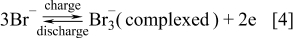
The vanadium-polyhalide and vanadium bromide batteries were also invented at UNSW by Skyllas-Kazacos and coworkers.10, 127 The cells employ the V(II)/V(III) couple and the Br−/Br3 − couple in the negative and positive half-cells respectively with the following cell reactions
Positive Half-Cell Reactions
Negative Half-Cell Reactions
Preliminary studies were carried out with a 3–4 M vanadium-bromide solution in the negative half-cell and a 8–10 M HBr solution in the positive half-cell by Skyllas-Kazacos107 followed by evaluation of membrane materials.152 For this concentration of active ions, it was possible to reach energy densities up to 50 Wh kg−1.10, 127, 152 This cell showed rapid loss of capacity however due to the transfer of vanadium ions across the membrane into the positive half-cell solution because of the large difference in ionic strength between the two half-cell solutions. To overcome this osmotic pressure effect, vanadium bromide was added to both half-cells, giving rise to the current G2 (second generation) V-Br cell technology that employs the same electrolyte in both half-cells. As with the all-vanadium battery, the G2 V-Br also overcomes the problem of cross contamination, but the higher solubility of vanadium halides compared with vanadium sulphate salts, allows much higher energy densities to be achieved. This technology was also patented in 2008.153
Further development of the V-Br technology was carried out by UNSW and V-Fuel Pty Ltd between 2005 and 2010 leading to the identification of highly stable, low cost membranes and electrode materials for the cell, in addition to the evaluation of bromine complexing agents such as tetrabutylammonium bromide, N-ethyl-N-methylpyrrolidiniumbromide (MEP), and N-ethyl-N-methylmorpholiniumbromide (MEM) to prevent the formation of bromine vapor during charge.126 A feature of the G2 V-Br is the formation of a two-phase electrolyte system in which the bromine complexes separate out into an organic phase during charging, the stability of which is a function of temperature and state-of-charge. Unfortunately the current complexing agents are too expensive for commercial application, so commercialisation of the G2 V-Br will be dependent upon the successful development of improved, low cost complexing agents that produce stable bromine complexes over a wide temperature (0–50°C) and SOC ranges.
Vanadium-cerium
The best temperature–concentration conditions for the vanadium-cerium RFB electrolytes appear to be 40°C and 1 M sulphuric acid, where the relatively good solubility of both cerium species, the maximum values of redox potentials, and the more or less satisfactory stability of glassy carbon electrodes were found.109 Even so, the relatively low solubility of cerium salts in sulphuric acid media and slow redox kinetics of the Ce3+/Ce4+ redox reaction at carbon indicate that the Ce3+/Ce4+ may not be well suited for use in RFB technology.109 Table IV gives more information on this system. As with all RFB that use different elements in each half-cell, however, problems of cross contamination would be expected in the V-Ce cell, requiring the use of mixed electrolytes. The use of mixed electrolytes would further reduce the solubility of each of the active materials in solution, and add to the cost of the system since twice the amount of active material is required, with half remaining un-reacted in each half-cell. Hence, further developments in this system have not been reported and given the inherent limitations, are difficult to justify.
Vanadium-cystine
It is shown for the vanadium-cystine system that during charge, water transfer is significantly restricted with increasing concentration of HBr when the Nafion 115 cation exchange membrane is employed.113 The same result can be obtained when Nafion 115 is replaced with gas diffusion layer (GDL) hot-pressed separator. However, the GDL separator has been shown to improve the performance efficiency of the vanadium-cystine system in comparison to the ion exchange membrane. More details on the RFB operation are given in Table IV. Given the low concentration of the active species however, very low energy densities would be expected, making this system impractical for commercial applications.
Other vanadium based redox flow systems
Other systems such as manganese-vanadium, vanadium-glyoxal(O2), vanadium acetylacetonate, vanadium polyhalide and vanadium-air were also investigated as highlighted in Table IV. To date, the highest energy efficiency has been obtained with the all-vanadium redox flow battery followed by the vanadium-bromine cell. With further research and development of suitable electrodes, membranes and electrolyte additives however, it might be possible to improve the performance of the other vanadium based redox flow cells, allowing them to be considered for different energy storage applications in the future. Important considerations for further development however, will be the need to demonstrate either a lower cost, higher energy efficiency, higher energy density or greater operating temperature range than the current VRB. This will require the stabilisation of active material concentrations greater than 2 M over a temperature range from 0°C to above 40°C, or the use of cheaper and more stable membranes and electrode materials than are currently used in the VRB.
Polysulphide-bromine
The sulphide-polysulphide system was first patented in 1983, opening up the future for research in the polysulphide-bromine redox flow battery.154 This system was found to be attractive for RFB applications due to abundance of the electrolyte, reasonable cost of chemicals and high solubility in aqueous media.68 The polysulphide-bromine redox flow battery, often referred to as the Regenesys cell, has a nominal open-circuit cell potential of 1.5 V and cell energy efficiencies of 60–65% depending on operating conditions. The cell operating temperature is typically between 20 and 40°C.68 Table VI summarizes the battery operating conditions briefly, while Table VII briefly describes the historical evolution of the technology.
Table VI. Operating conditions and technicalities of some possible commercial flow batteries excluding the all vanadium system.
| No. | Redox system | Electrolyte composition | Charge/Discharge Reaction at Electrodes | OCP (V) | Charge/Discharge current density (mA/cm2) | Electrode and membrane materials used | Charge/Discharge Efficiency (%) | References |
|---|---|---|---|---|---|---|---|---|
| 1 | Bromine-polysulfide | 5 M NaBr saturated with Br2 and 1.2 M Na2S | Positive electrode: 3Br− → Br3 − +2e−Negative electrode: S4 2− +2e− → 2S2 2− | 1.7–2.1 | 40 | Activated carbon/polyolefin pressed electrodes or nickel foam/carbon felt materials divided by a Nafion 115 or 117 membranes | 77.2 (overall) | 68, 154, 155 |
| 2 | Zinc-bromine | 1–7.7 mol dm−3 ZnBr2 with an excess of Br2 with additives such as KCl or NaCl | Positive electrode: 2Br− → Br2 + 2e−Negative electrode: Zn2+ + 2e− → Zn0(s) | 1.6 | 15 | Two carbon electrodes of 60 cm2 and 5 mm interelectrode gap separated by a Nafion 125 or polypropylene microporous membranes | 80 (overall) | 68; 156–158 |
| 3 | Zinc-cerium | Anolyte: 0.3 M Ce2(CO3)3 and 1.3 M ZnO in 70 wt.% methane sulfonic acid catholyte: 0.36 M Ce2(CO3)3 and 0.9 M ZnO in 995 g methane sulfonic acid | Positive electrode: 2Ce 3+ → 2Ce4+ + 2e –Negative electrode: Zn 2+ + 2e − → Zn0 (s) | 2.45 | 50 | Carbon plastic anodes and platinised titanium mesh cathodes of 100 cm2 geometrical area separated by a (non-specified type of) Nafion membrane | 98 (coulombic) | 68, 110, 158, 159 |
| 4 | Soluble lead-acid | Soluble lead (II) species in methanesulfonic acid | Positive electrode: Pb2+ + 2H2O → PbO2 + 2H+ + 2e–Negative electrode: Pb 2+ + 2e − → Pb (s) | 1.62 | 20 | Cathode and anode made of 70 ppi reticulated vitreous carbon and 40 ppi reticulated nickel, respectively | 60–66 (overall) | 68, 160, 161 |
Table VII. Historical Overview of the Bromine/Polysulphide Redox Flow Battery.
| Year | Electrode materials | Electrolyte | Membrane | Battery type | Comment | References |
|---|---|---|---|---|---|---|
| 1984 | Graphite and porous sulphide nickel electrodes | 1 M NaBr saturated with Br2 and 2 M Na2S | Nafion 125 membrane | Single flow cell | Electrode area of 35 cm2 and 0.25 cm inter-electrode gap was common and managed to generate an open circuit potential of 1.74V; the open circuit potential at 50% charge was 1.5V | 154 |
| 1999 | Activated carbon/polyolefin pressed electrodes | 5 M NaBr as anolyte and 1.2 M Na2S as a catholyte | Nafion 115 membrane | Monopolar redox flow cell | During the charging cycle for 30 min at 40mAcm−2 the cell voltage climbed sharply from 1.7 to 2.1V | 68 |
| 2001 | Carbon-polyelfin composite bipolar electrode using specialized filter press type flow cell assembly | Tribromide/bromide and polysulphide/sulphide electrolytes | Sodium cation exchange membranes (Du Pont) | The S (small), L (large), and XL (extra large) series cell stacks | The technology has been demonstrated up to the XL scale in a 1-MW maximum pilot scale facility at Innogy's Aberthaw power station, near Cardiff, UK, over the last 5 years | 162 |
| 2004 | Nickel catalyst supported on carbon for negative electrode. Platinum catalyst supported on carbon for positive electrode | The initial negative electrolyte was 2.0 mol/l Na2S2solution. The initial positive electrolyte was 1.0 mol/l Br2 dissolved in 2.0 mol/l NaBr solution. | Nafion | Single flow cell | A power density of up to 0.64 W/cm2 (V = 1.07 V) was obtained in this energy storage cell. A cell potential efficiency of up to 88.2% was obtained when both charge and discharge current densities were 0.1 A/cm2 | 163 |
| 2005 | Nickel foam and carbon felt materials were used as negative and positive electrodes | Anolyte was 1.3 M Na2S4 + 1 M NaOH aqueous solution while catholyte was 4 M NaBr aqueous solution | Nafion 117 cationic membrane | Single flow cell | Internal ohmic resistance of the cell restricted the overall energy efficiency to 77.2%, at current density of 40 mA cm−2 and cell power density of 56 mW cm−2 | 155 |
| 2007 | Polyvinylidene-difluoride (PVdF) and activated carbon composite laminated on HDPE/carbon core | 1 M of NaBr in 0.5 M Na2SO4 at pH 2 | Nafion 115 cation exchange (ca. 125 µm dry film thickness) | Five cell bipolar reactor (filter-press type) | Mass transport, pressure drop and fluid dispersion was measured using the reactor and battery efficiency wasn't determined. | 164 |
Technical challenges with this system have included:68, 165
- (a)cross-contamination problems of both electrolyte solutions over a period of time;
- (b)The difficulty in maintaining electrolyte balance;
- (c)The possibility of deposition of sulphur species on the membrane; and
- (d)The need to prevent H2S(g) and Br2(g) formation.
Most of the development of the polysulphide-bromine system was carried out by Innogy in the 1990s and considerable advances were made with stack design and fabrication. Numerical modelling of the polysulfide-bromide (PSB) system revealed that mass transport overpotentials at the bromide electrode limit the performance during discharge.166 The model showed that significant drift in conditions could occur due to self-discharge and electro-osmotic effects. Careful electrolyte management was suggested to ensure reliable operation of the polysulphide-bromine RFB system. Because of the complexity of the electrolyte management system, however, it was decided to restrict the application of the polysulfide-bromide RFB to MW-scale installations where the electrolyte maintenance costs would not be prohibitive. A separate mathematical model incorporating capital and operating costs to predict the technical and commercial performance of the polysulphide-bromine RFB at a 120MWh/15MW utility-scale storage plant for arbitrage applications revealed a net loss of US$0.0073/kWh at an optimum current density of 500 Am−2 and an energy efficiency of 64%,167 indicating the need for further cost reduction. Furthermore, unlike the V-Br cell, the polysulphide-bromine cell has not utilised complexing agents to bind any bromine produced at the positive electrode during charging, and this has often been seen as a considerable safety risk with this technology. Hence, considerable research is still required to ensure that this system overcomes current techno-economic constraints and safety concerns in order to become a widespread commercialized technology.
Actinide based redox flow battery
These systems were very briefly mentioned in the previous review paper.68 Two systems have been proposed as a means of utilizing excess depleted actinides for energy storage purposes. One involved the neptunium couples Np3+/Np4+ and NpO2 +/NpO2 2+ in aqueous solution168 while the other considered the use of uranium {U(IV)/U(III) and U(VI)/U(V)} couples in organic solvents.169–173 An open circuit potential of around 1 V was estimated for the all-uranium couples complexed by a range of β-diketone ligands.174 Besides this, charge/discharge test data of the all-uranium redox flow battery have not been provided as yet. The same is the case for the all-neptunium redox couple system, although theoretical calculations have revealed that an all-neptunium battery can produce energy efficiencies ranging from 40 to 99.1%,175, 176 with 99.1% efficiency obtainable at 70 mA/cm2. Some more details on the system are given in Table VII.
A major obstacle in the development of actinide-based RFB, is the use of radioactive redox species that is likely to encounter significant consumer resistance. Special precautionary measures and a thorough investigation will therefore need to be conducted to evaluate their safety and environmental implications before commercialization. For example, the high radioactivity of neptunium has limited the practical evaluation of the all-neptunium redox flow battery so that only theoretical estimations of energy efficiencies are available by means of mathematical modeling.176
Other flow cell developments
The latest redox flow battery chemistries that are currently being developed are summarized in Table VIII. The zinc-nickel hybrid system appears to give an energy efficiency of 86% (Ref. 181) comparable to the all-vanadium RFB, followed by the tiron/Pb redox flow battery.180 The zinc-nickel hybrid system utilises the Zn(II)/Zn and Ni(III)/Ni(II) redox couples. Since this system uses a single electrolyte and produces solid products at the electrodes during charging, it does not require a membrane, so its cost is likely to be less than most conventional redox flow battery systems.182 Theoretically, the deposition/dissolution of zinc on inert metal current collectors can be cycled endlessly.185 However, that is not possible practically due to formation of zinc dendrites during charging. Researchers have studied the morphology of zinc dendrites and found that at higher electrolyte flow rates (> 15 cm s−1) good cycle life for the battery can be obtained at 100% depth of discharge.186 Complete discharge is however a critical requirement for the long-term prevention of dendrites, and this produces an operational restriction on any cell employing the Zn2+/Zn couple. In addition, the cycle life of the zinc-nickel single flow battery is dependent on the stability of nickel oxide electrodes in the presence of zinc ions in the electrolyte that lowers the discharging capacity of the nickel oxide electrode. Cheng et al found however, that in concentrated KOH electrolytes containing 20 g l−1 LiOH, addition of 0.4 M ZnO to the electrolyte actually enhanced the stability of the nickel oxide electrodes during a cell cycling.185 The potential for Zn dendrite formation will however be the major technical challenge for the zinc-nickel flow cell and electrolyte additives that can prevent dendritic growth during partial discharge operation is an area for further research and development.
Table VIII. Properties of actinide based redox flow batteries and other novel systems developed after publication of previous review paper (Ref. 68).
| No. | Redox system | Electrolyte composition | Charge/discharge Reaction at Electrodes | OCP (V) | Charge/discharge current density (mA/cm2) | Cell type | Electrode and membrane materials used | Charge/discharge Efficiency (%) | References |
|---|---|---|---|---|---|---|---|---|---|
| 1 | All-neptunium | 1 M nitric acidic solution of 0.05 M neptunium | Positive electrode: Np3+ → Np4+ + e−Negative electrode: NpO2 2+ + e − → NpO2 + | 1.3 | 70 | Stationary H-type cell | c-Plane carbon of pyrolytic graphite and plastic formed carbon. A-511 anion exchange membrane used. | 99.1 (predicted via mathematical modelling) | 175, 176 |
| 2 | All-uranium | U(VI)/U(V) β-diketonate solution as the catholyte and U(IV)/U(III) β-diketonate solution as the anolyte | Positive electrode:U(IV) → U(V) + e−Negative electrode:U(IV) + e − → U(III) | 1.1 | 75 | Stationary H-type cell | A platinum working electrode (1.6φ), a Ag/AgNO3 reference electrode prepared with a corresponding solvent and a 10 × 10 mm platinum plate counter electrode were used. | Not measured nor predicted | 169–173 |
| 3 | All-chromium | 0.2 M chromium EDTA complex in HCl | Positive electrode: [Cr(III)EDTA(H2O)]− → [Cr(V)EDTA(H2O)]+ + 2e−Negative electrode: 2[Cr(III)EDTA(H2O)]− + 2e− → 2[Cr(II)EDTA(H2O)]2− | 2.11 | 30 (during charge) 2.5 (during discharge) | Flow cell | Graphite felt electrodes thermally pre-treated at 500°C in muffle furnace to reduce its hydrophobic nature | 15% with stationary H-type cell and 7% with undivided redox flow battery | 34, 177, 178 |
| 4 | Zinc-air | 0.4 M ZnO in 6 M KOH solution was employed as the catholyte and propanol of different concentrations in 6 M KOH solution was employed as the anolyte. | Positive electrode: Propanol oxidation during charging; oxygen reduction during discharge.Negative electrode: Zn(OH)4 2− + 2e− → Zn + 4OH− | 1.705 | 20 | Not given | Sintered nickel electrodes are employed as positive electrodes, and inert metal current collectors are employed as negative substrate electrodes. | 59.2 (overall) | 179 |
| 5 | Tiron | 0.25 M tiron in 3 M H2SO4 as cathodic active species and the lead electrode as anodic active species | Positive electrode: [Tiron] + 2H+ + 2e− → [Tiron]−Negative electrode: Pb + SO4 2− → PbSO4 + 2e− | 1.10 | 10 | Not given | Cation-exchange membrane (Nafion 115, Du Pont) was used as a separator. A graphite felt electrode (10 mm in thickness) contacted against one graphite plate was used as the working electrode. A lead negative electrode with an area of around 20 cm2 and a SCE electrode were used as the counter electrode and reference electrode, respectively. | 82 (overall) | 180 |
| 6 | Zinc-nickel | Highly concentrated solutions of ZnO in aqueous KOH | Positive electrode: 2NiOOH + 2H2O + 2e− → 2Ni(OH)2 + 2OH−Negative electrode: Zn + 4OH− → Zn(OH)4 2− + 2e− | 1.705 | 10 | Flow cell | The negative electrode is inert metal such as nickel foil, and the positive electrode is nickel oxide. No membrane requirement. | 88 (overall) | 181, 182 |
| 7 | [Ru(acac)3] | 0.02 M ruthenium acetylacetonate with 0.1 M tetraethylammonium tetrafluoroborate dissolved in acetonitrile | Positive electrode: Ru(acac)3] → [Ru(acac)3]+ + e−Negative electrode: [Ru(acac)3] + e− → [Ru(acac)3]− | 1.76 | 0.28 (charge)0.056 (discharge) | Flow cell | Graphite felt electrodes in undivided flow-through electrochemical reactor | 5 (overall) | 17, 183 |
| 8 | Cr(acac)3 | 0.05 M Cr(acac)3 and 0.5 M TEABF4 dissolved in acetonitrile | Positive electrode: Cr(acac)3] → [Cr(acac)3]+ + e−Negative electrode: [Cr(acac)3] + e− → [Cr(acac)3]− | 3.4 | 0.14 (charge) 0.014 (discharge) | Stationary H-type cell | Graphite electrodes | 55 (coulombic) 20 (overall) | 184 |
In the case of the tiron-Pb redox flow battery studies, it is interesting to note that tiron (4,5-dibenzoquione-1,3-benzenedisulfonate) was investigated in aqueous environment whereas a similar aromatic species (rubrene) was investigated in organic media76 and gave very poor electrochemical performance. It may be interesting to investigate tiron in organic media and compare its performance with that of the aqueous system to assess its suitability as active species in the positive electrolyte of a RFB. On top of that, a preliminary understanding of its electrode reaction mechanism in both acidic aqueous solutions and organic solvents may be attempted in an undivided redox flow battery similar to the reactor reported by Chakrabarti and co-workers.12, 13, 178, 187–189
An all-chromium redox cell was investigated by Bae and co-workers,93, 178 building on an original proposal by Chen and co-workers.190 The static, H-type cell employed chromium-EDTA complex as redox species in HCl media and an energy efficiencies of 15% was reported93 whereas for the same redox species in a flowing undivided battery, poorer efficiencies of 7% were obtained.178 Although static H-type cells are unlikely to produce good performance because of poor cell geometry, it should be mentioned that the all-vanadium redox species showed much better performance when tested in similar cell designs.183, 187–189 However, recent studies on chromium acetylacetonate redox couple complexes in H-type glass cells gave comparable charge/discharge performance to vanadium acetylacetonate in acetonitrile.114, 184 Overall efficiencies of 20% or less were obtained with these organic based systems similar to those achieved with an all-ruthenium redox flow battery (Fig. 2) using acetonitrile as the solvent.12, 187–189 High cost and low efficiencies have however limited the application of organic solvents for the redox flow battery.
Methylimidazolium iron chloride molten salt system has also been considered for redox flow battery applications.191 It was predicted that if a sodium chloride-sodium electrode was combined with this EMICl–FeCl2–FeCl3 molten salt, a high energy density per unit volume may be expected. Since Na(I)/Na couple in EMICl–AlCl3 system has the formal potential of − 2.15 V at room temperature,192 the electromotive force of approximately 2 V can be expected for the Na/EMICl–FeCl2–FeCl3 battery. Although this battery appears to have the advantage of a low operation temperature and a long cycle life compared with Na–S and Zebra cells,193 further work with this system appears to be lacking in the literature as focus has been more towards the all-vanadium and polysulfide-bromide systems over the years. One reason for the lack of activity in the area of ionic liquids for flow batteries is the fact that these materials are known to be sensitive to air and moisture, making their handling difficult in large-scale commercial applications. Although other ionic liquids that are not as sensitive to air and moisture may be found, these materials also tend to be quite expensive and are unlikely to be economically viable for these types of applications compared to the lower cost aqueous systems. Given the large electrochemical window of many ionic liquids however, the possibility of using redox couples that fall outside the decomposition potential of water, may open the way to the development of high voltage flow cells that offer much higher power and energy densities than current aqueous systems. Further investigation of such couples could therefore prove fruitful as long as practical systems can be shown to offer better performance, cell voltage and cycle life than the VRB and PSB systems to offset the high costs of these electrolytes.
The electrochemical behavior of the Fe(III)/Fe(II)–triethanolamine(TEA) complex redox couple in alkaline medium and the influence of the concentration of TEA were investigated recently.192 A change of the concentration of TEA mainly produces the following two results:
- (1)With an increase of the concentration of TEA, the solubility of the Fe(III)–TEA can be increased to 0.6 M, and the solubility of the Fe(II)–TEA is up to 0.4 M.
- (2)In high concentration of TEA with the ratio of TEA to NaOH ranging from 1 to 6, side reaction peaks on the cathodic main reaction of the Fe(III)–TEA complex at low scan rate can be minimized.192
The electrode process of Fe(III)–TEA/Fe(II)–TEA was shown to be electrochemically reversible with higher reaction rate constant than the non-complexed species.93 Constant current charge–discharge showed that applying anodic active materials of relatively high concentrations facilitates the improvement of cell performance. The open-circuit potential of the Fe–TEA/Br2 cell with the Fe(III)–TEA of 0.4 M concentration, after full charging, is nearly 2 V and is about 32% higher than that of the all-vanadium batteries, while the energy efficiency is comparable at approximately 70%.93 Although the active material concentrations used to date have been too low for practical application, further optimization of the electrolyte composition may establish its potential for future commercialization.
Chemically regenerative redox fuel cells
The chemically regenerative redox fuel cell is a type of fuel cell that employs redox couple solutions as electron mediators for the fuel and oxidant reactions. A chemically regenerative redox fuel cell is thus a type of flow cell since it contains two redox couples which are circulated past the electrodes, and after electrochemical reaction at the electrodes, the solutions are passed into regeneration reactors where they are re-reduced or re-oxidized by the reductant and oxidant respectively. After the regeneration step the solutions are once more circulated past the electrodes, and the process proceeds. Most of the early work on redox fuel cells was reported by Kummer and Oei194–196 whose work has shown the advantages and the limitations of the redox fuel cell. These workers investigated a wide range or redox couples, the main criterion for selection being the feasibility to regenerate the charged species using hydrogen and/or oxygen for the negative and positive half-cell reactants respectively, while also attaining the required power density for electric vehicle applications.195, 197 Other workers evaluated different membranes for redox fuel cells119, 198 and regeneration reactants.199, 200 The main attraction of this concept is the possibility of avoiding catalysts at the electrode surface and of using simple (inexpensive) electrode materials. Although hydrogen was the original fuel of choice, the concept offers a freedom of choice of fuels. The main disadvantage of using hydrogen for the regeneration of the negative half-cell active species is the relatively high reversible potential for the hydrogen couple that limits the range of redox couples that can be used in the negative half-cell. On the other hand, early studies194–196 also showed that the oxidative regeneration of the positive half-cell couple using air or oxygen, is also kinetically slow, requiring relatively expensive catalysts that negate the main purpose of this approach.
More recently, a group of researchers from the University of British Columbia and the National Research Council of Canada has been working on two new approaches for a direct liquid redox fuel cell (DLRFC) in which the air cathode of a regular direct methanol liquid fuel cell is replaced with a metal-ion redox couple over a carbon cathode. For example, in a Fe-methanol fuel cell, methanol is used as the fuel and Fe3+ is used as oxidant. When the Fe3+ is depleted, the Fe2+ is passed through a separate regeneration cell where it is reacted with oxygen gas at the anode to reform the Fe3+ reactant for the fuel cell. In the DLRFC described by Ilicic et al.201 however, spontaneous redox couple regeneration is achieved by simply substituting the methanol anolyte with an air stream on the anode side. The methanol anode then becomes an air cathode, which reverses the direction of electron flow and regenerates the Fe3+ oxidant in the DLRFC.
The first approach uses mixed-reactant operation that involves supplying a mixed methanol Fe2+/Fe3+ redox electrolyte only to the carbon cathode. Spontaneous methanol crossover supplies the fuel to the anode. This approach eliminates problems associated with the oxygen diffusion electrode and has the potential to significantly improve the cost, compactness, and volumetric and gravimetric power densities of the cell. The second approach is the in situ regeneration of the redox couple by supplying air to the methanol anode that then becomes an air cathode, which reverses the direction of electron flow and regenerates the redox couple on the other electrode.201, 202
Hybrid Flow Battery Technologies
Zinc-hybrid technology
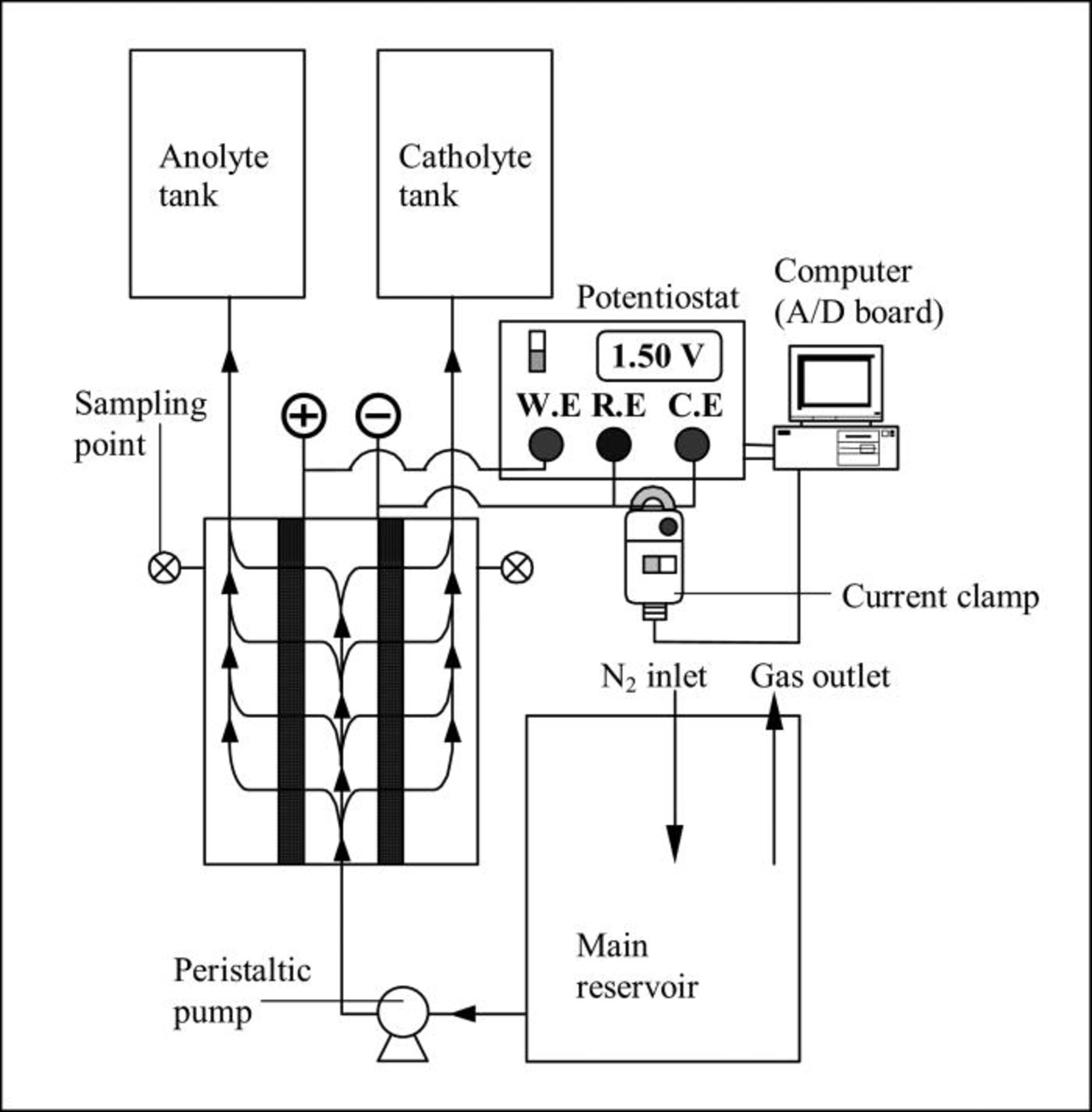
Hybrid flow batteries are distinguished from conventional redox flow batteries by the feature that at least one redox couple species is not fully soluble and may be either a metal or a gas. A number of hybrid flow cells were listed in Tables VI and VIII, but the most widely known of these is the zinc-bromine battery. The underlying concept of the zinc-bromine battery was first proposed more than 100 years ago, but in the mid 1970s and early 1980s, Exxon and Gould pioneered the initial designs for practical application. The zinc-bromine hybrid system, ranging in size from 50 to 400 kWh, is capable of storing energy for 2–10 h at efficiencies of 70% or higher158 Coulombic and voltage efficiencies were reported to be around 90 and 85% respectively, whereas the energy density is around 65–75 Wh kg−1 (Ref. 159) The system is briefly summarized in Table VI and a schematic of the zinc-bromine hybrid system is given in Fig. 3.127
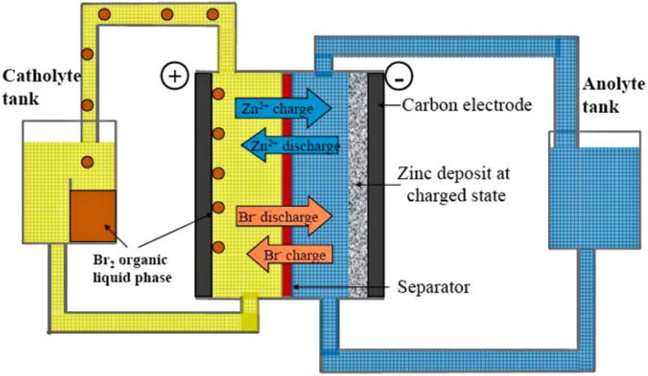
Figure 3. (Color online) Schematic of Zinc-Bromine Flow Battery (Ref. 127). Figure reproduced with kind permission from Woodhead Publishing Limited, Cambridge, UK.
In order to optimise the zinc-bromine battery, various mathematical models have been used to describe the system.203–206 The problems with the zinc-bromine battery include high cost electrodes, material corrosion, dendrite formation during zinc deposition on charge, high self-discharge rates, unsatisfactory energy efficiency and relatively low cycle life68 Another disadvantage of this system is slow kinetics of the bromine/bromide couple that causes polarization and loss in voltage efficiency. To overcome this, high surface area carbon electrode on the cathode side is normally used to reduce the effective current density, however, the active surface area of the carbon eventually decreases and oxidation of the carbon coating occurs.68
In zinc-bromine hybrid systems, the energy storage and power of the battery are not fully decoupled as the energy storage capacity will depend on the thickness and morphology of the metallic layer formed. A porous separator is often used between the positive and negative electrodes to avoid the reduction of dissolved bromine during charge68 however bromine cross-over is still an important issue, as is the problem of dendritic growth and shorting. Electrolyte additives (e.g., quaternary ammonium salts) can be used to complex any dissolved bromine that has been inadvertently transported through the membrane to the zinc half-cell.207 However, its performance does not match that of the all-vanadium RFB as yet and is mainly being developed for smaller applications up to 500 kWh. The main reason for the limited attention has been the operational limitations associated with the need to prevent zinc dendrites. Despite extensive work to optimise the design of electrolyte channels and manifolds to minimise shunt currents, zinc dendrites can still form after extended cycling, causing channel blockage and shorting through the separator. This is typically overcome by regular full discharge to completely strip all of the zinc from the negative plates to eliminate sites where dendrites can grow. This requirement creates undesirable operational restrictions, so further work on electrolyte additives to inhibit dendritic growth is an area that could yield considerable benefits for the future implementation of this technology.
Despite these problems with zinc plating, however, the very negative potential of the Zn2+/Zn couple continues to make this half-cell attractive for flow cell applications. The zinc-cerium hybrid redox flow battery is one such system that combines the very negative zinc couple with a very positive cerium couple to yield a cell voltage of more than 2 V and an OCP that is higher than any of its commercial competitors.163 The zinc-cerium has been under development since the early 1990s by Electrochemical Design Associates Inc.159 and some of its properties are given in Table VII. The testing and development of this system has been undertaken by Plurion Systems Limited. This hybrid flow cell involves the use of salts of zinc and cerium in an organic solvent.68, 208 It has some similarity to the zinc-bromine system in that the negative half-cell redox couple involves a solid zinc phase. It also uses an environmentally benign organic acid as the solvent (not degraded by cross-membrane migration) and a common electrolyte system in both half-cells.
Mathematical modelling to understand the redox nature of the Ce(IV)/Ce(III) redox couple has also been conducted for a batch system comprising an electrochemical reactor and an electrolyte circuit.209 The batch recycle system consisted of a pumped flow through divided FM01-LC parallel-plate electrochemical reactor (64 cm2 projected electrode area) and a well mixed tank (3600 cm3). Unfortunately, significant differences between experimental and predicted values were found at long electrolysis times. This was partly attributable to the presence of solvated species and complex formation involving Ce(III) and Ce(IV) species, which modified the actual concentration of Ce(III) and Ce(IV) from the predicted values.209 This has limited the energy density of the zinc-cerium system to date, however, further research may help to address this limitation, allowing it to compete commercially with the all-vanadium RFB.
Other zinc hybrid systems (such as zinc-nickel) have been developed recently and will be discussed in later sub-sections of this paper.
Flowing undivided lead acid battery technology
The system differs from the traditional lead-acid battery since it uses a highly soluble form of the Pb(II) species that is supplied as a aqueous acid electrolyte for both the negative and positive half-cells reactions.68 It also differs from conventional redox flow batteries since it uses a single electrolyte and involves the formation of solid products at the two electrodes during charging, so that no separator or membrane is necessary. This reduces the cost and design complexity of the batteries significantly68 Some properties of the system are described in brief in Table VI, while a schematic representation of the system is given in Fig. 4.
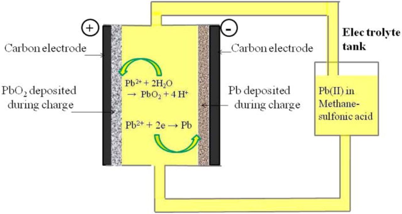
Figure 4. (Color online) Undivided Lead Flow Cell.
The electrode reactions involve the conversion of the soluble species into solid Pb and PbO2 phases at the negative and positive electrodes respectively during charging and re-dissolution during the discharging cycles. The deposition of solid phases on the electrodes during charging introduces complexities to the electrode reactions that may reduce the performance of the battery if the metal grows across the inter-electrode gap and short circuits the battery.68 Dissolution and deposition of lead is fast and no overpotentials are usually required, however as with conventional lead-acid batteries, hydrogen evolution is observed during the charge cycle at high state-of-charge, thus reducing storage capacity.210 These cells have been studied in several electrolytes; percholoric acid, hydrochloric acid, hexafluorosilicic acid, tetrafluoroboric acid and most recently in methanesulphonic acid.68, 161, 210–212
The structure of lead deposits (approximately 1 mm thick) formed in conditions that are met at the negative electrode during the charge/discharge cycling of a soluble lead-acid flow battery was examined in some detail by Pletcher et al.213 The quality of the lead deposit could be improved by appropriate additives and the preferred additive was shown to be the hexadecyltrimethylammonium cation, C16H33(CH3)3N+, at a concentration of 5 mM. In the presence of this additive, thick layers with acceptable uniformity could be formed over a range of current densities (20–80 mA cm−2) and solution compositions.213 While electrolyte compositions with lead(II) concentrations in the range 0.1–1.5 M and methanesulfonic acid concentrations in the range 0–2.4 M have been investigated, the best quality deposits are formed at lower concentrations of both species. Surprisingly, the acid concentration was more important than the lead(II) concentration; hence a possible initial electrolyte composition for an efficient system was postulated to be 1.2 M Pb(II) + 5 mM C16H33(CH3)3N+ without added acid.212 The system was predicted to be cycled between 0.2 M Pb(II) + 2 M CH3SO3H at top of charge to 1.15 M Pb(II) + 0.1 M CH3SO3H at bottom of charge. Also the current density was expected to be up in the range of 20–80 mAcm−2 for suitable operation of the system.214
Extensive cycling of the soluble lead flow battery has revealed unexpected problems with the reduction of lead dioxide at the positive electrode during discharge.214 This has led to a more detailed study of the PbO2/Pb2+ couple in methanesulphonic acid. The variation of the phase composition measured by XRD and deposit structure measured using SEM have been defined as a function of current density, Pb2+ and H+ concentrations, deposition charge and temperature as well as the consequences of charge cycling.214 Pure α-PbO2, pure β-PbO2 and their mixtures can be deposited from methanesulphonic acid media successfully. The α-phase deposits as a more compact, smoother layer, which is well suited to charge cycling. While the anodic deposition of thick layers of PbO2 is straightforward, their reduction is not; the complexities are explained by an increase in pH within the pores of the deposit. The results suggest that operating the battery at lead(II) concentrations < 0.3M and elevated temperatures should be avoided.214
It has been demonstrated that extended cycling of the soluble lead acid battery in a 10 × 10 cm parallel plate cell is possible, with greater than 100 cycles achievable under some conditions.215 Eventual failure is, however, inevitable if the battery is operated under conditions where solids are allowed to accumulate continuously on the two electrodes. Failure usually results from: (a) shorting of the electrodes owing to lead dendrites formation largely around the edges of the negative electrode plate and (b) poor adhesion of PbO2 to the positive electrode surface leading to particles in the electrolyte and loss of active material.215
Extended cycling of the battery can lead to problems due to an imbalance in the coulombic efficiency of the negative and positive charging reactions that produce deposits of Pb and PbO2 on the electrodes.160 Periodic addition of hydrogen peroxide to the electrolyte largely overcomes several operational problems seen during extended cycling. It is shown that this treatment greatly extends the number of cycles that can be achieved with a reasonable energy-, voltage-, and charge efficiency of 54–66, 71, and 77–91%, respectively.160 Further research and development is necessary before the soluble lead acid battery can be considered for commercial scale projects.
The hybrid oxygen redox fuel cell
A further extension of the chemically regenerative redox fuel cell is the hybrid redox fuel cell concept that employs a redox couple electrolyte for the negative half-cell, but the positive half-cell electrolyte is replaced by air or oxygen. Like a conventional fuel cell, air or oxygen is fed through a gas diffusion electrode in the positive half-cell, but in contrast to the fuel cell, the negative half-cell reactant comprises a soluble redox couple electrolyte, as illustrated in Fig. 5. By replacing the positive half-cell electrolyte reaction with an air or oxygen gas diffusion electrode, the total electrolyte volume is reduced by half, effectively doubling the energy density of the system.
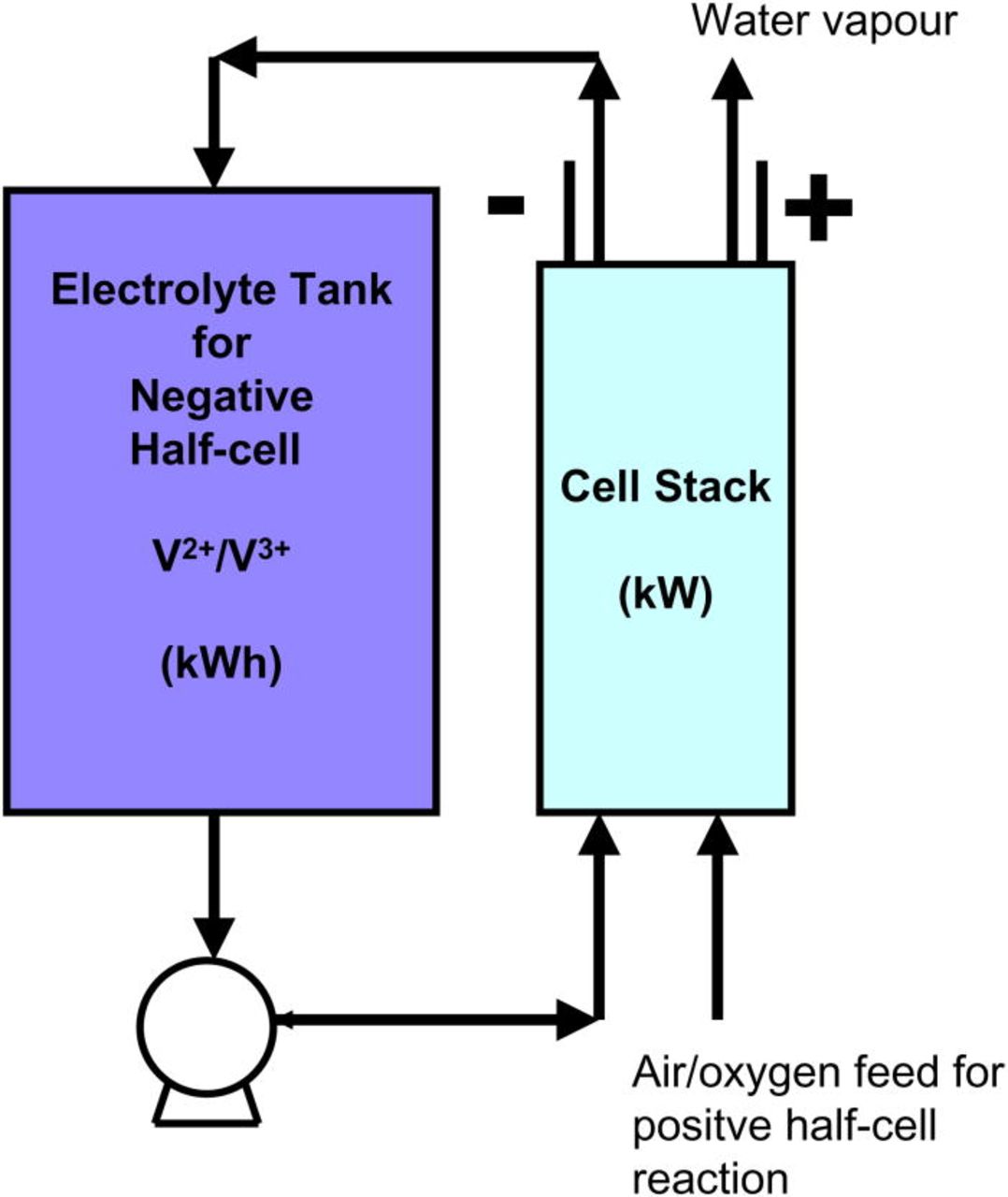
Figure 5. (Color online) Schematic of V-O2 Redox Fuel Cell.
The vanadium-oxygen redox fuel cell (VOFC) concept was initially proposed by Kaneko and co-workers in 1992 (Refs. 115, 116) and first evaluated at UNSW by Menictas and Skyllas-Kazacos in 1997.63, 216 In this project the performance of the VOFC over a range of temperatures and using different types of membranes and air electrode assemblies was evaluated. Despite early problems with the membrane electrode assemblies that saw separation of the membrane due to swelling and expansion during hydration, with improved fabrication techniques, this problem was minimized and it was possible to operate a 5-cell VOFC system for a total of over 100 h without any deterioration in its performance.63
With renewed interest in electric vehicles, the VOFC concept has recently received further attention with a range of reports emerging from the Fraunhofer Institute217 and Twente University in the Netherlands218 Hosseiny et al.218 reported the effective quadrupling of the energy density of the VCFC relative to the conventional all-vanadium redox battery by the use of 4 M vanadium solutions in the negative half-cell. The elimination of the positive half-cell reactant also eliminates the problem of thermal precipitation of V(V) species at high temperatures that currently restricts the upper temperature range of the VRB to 40°C. Without a threat of thermal precipitation, the researchers were able to operate the cell at 80°C, thereby achieving 4 M solubilities for the V(II) and V(III) species in the sulphuric acid negative electrolyte. This is a major advance in the development of a high energy density VOFC that could find application in electric vehicles, however, an issue that would need to be addresses is the requirement to maintain high temperatures in the negative electrolyte tanks and half-cells to prevent precipitation of the vanadium ions on cooling to room temperature. The evaluation of alternative supporting electrolytes that can give high solubilites for V(II) and V(III) ions at room temperature is therefore an area that requires further attention.
Application and Commercial Status of Flow Batteries
Of all of the flow battery systems that have been researched and developed in the last 30 or so years, the only technologies that have come close to full-scale commercialisation are the iron-chromium, all-vanadium, zinc-bromine and sodium-polysulphide systems. Their applications and current status is evaluated in brief in this section.
Early iron-chromium battery demonstrations and recent commercialisation
The first 1 kW prototype Fe-Cr systems was developed in 1980 by NASA.91 The Fe-Cr redox flow battery was installed and tested in a photovoltaic system but results were not sufficiently satisfactory for consideration of a full-scale prototype. Further work in Japan in the 1980s did however lead to the development of a 10 kW Fe-Cr redox battery prototype with an 80% energy efficiency and 300 life cycles, as demonstrated by Shimizu and co-workers (Kansai Electrical Power Co., Amagasaki, Japan).219 Operations involving the catholyte and anolyte circulation rates (in a 10 kW Fe-Cr redox-flow battery) to save energy, and a method of rebalancing were described by Nakamura (Mitsui Ltd., Japan).220 Other similar prototype systems were developed and tested by NASA (Ref. 85) as well as in Japan95 for different applications while a 0.1 MW pilot scale unit was evaluated in the mid 1990s in Spain.81 Commercial development of the Fe-Cr battery was however abandoned because of problems of cross-contamination between anolyte and catholyte, poor energy efficiencies due to hydrogen evolution at the negative electrode and fouling of the ion-exchange membranes.68 Hence, this system was largely ignored during the late-1990s and early 2000s. In the late 2000s however, the Fe-Cr battery was revisited by a US-based technology company, Deeya Energy,221 when the world prices for vanadium briefly peaked at close to 4 times historical average prices and the company saw the Fe-Cr system as a potentially lower priced product than the VRB.
All-vanadium redox flow battery
The all-vanadium redox flow battery has to date shown the greatest potential for large-scale energy storage applications with long cycle life and high energy efficiencies of over 80% in large installations.15–20 This technology has already been applied in a MW- scale and several kW scale projects,222–231 with many practical demonstrations covering a range of stationary and mobile applications in countries such as Japan, Europe, Australia and the USA.79, 222–225 One of the main advantages of the vanadium redox flow battery that distinguishes it from most other flow battery systems is the use of the same element in both half-cells that prevents cross contamination and a theoretically indefinite electrolyte life. It also exhibits a low cost for large storage capacities; cost per kWh decreases as energy storage capacity increases and typical projected battery costs for eight or more hours of storage are as low as US$150/kWh.127
Since 1993 a number of field trials of the vanadium battery were been undertaken both by UNSW as well as in Thailand and Japan. In collaboration with UNSW Centre for Photovoltaic Devices and Systems and licensee Thai Gypsum Products Ltd., a vanadium battery storage system was installed in a demonstration Solar House in Thailand.10, 60, 61
The solar energy system included 2.2 kW of installed solar cells and a 12 kWh vanadium battery. The original battery had 12 cells giving a system voltage of 16.8 V and used 200 l of each half-cell electrolyte in the two reservoirs.60 A 48 V, 36 cell stack was later constructed in the laboratory and tested with a 4 kW inverter and specially designed battery controller, prior to installation in the demonstration Solar House in Thailand. The 48 V batteries replaced the original 12-cell stack for long-term field trials. The microprocessor controller built by the UNSW Centre for Photovoltaic Systems and Devices, was designed to optimise the efficiency of the battery for this application.60, 127 This included the use of a pump control system that only switched on the pumps if the current exceeded a pre-set value. At lower loads, the pumps would only turn on for a few minutes at a time when the stack voltage dropped below 1 V, thereby allowing the electrolyte within the cell stack to be replenished. This simple on-off pump controller significantly reduced the pumping energy losses so as to maximise the overall energy efficiency of the system.
In 1993, a consortium comprising Mitsubishi Chemicals and Kashima-Kita Power Corporation of Japan licensed the UNSW vanadium battery technology for stationary uses and for the next 5–6 years spent several million US dollars per annum to scale up the technology for large-scale load-levelling and solar energy storage applications.10, 127 Kashima-Kita Electric Power Corporation employs vanadium rich Venezuelan pitch as the fuel for electricity generation, thus producing a high vanadium content fly-ash as a waste product. An efficient chemical process was developed to extract the vanadium from the fly-ash which is then used to produce a low-cost vanadium electrolyte for the vanadium redox flow battery. A 3 m3 d−1 electrolyte production plant was commissioned in early 1996.10, 127
In 1997, a 200 kW/800 kWh grid-connected vanadium battery was commissioned at the Kashima-Kita Electric Power station in Japan where it underwent long-term testing as a load-levelling system. By the beginning of 1998, it had already undergone 150 charge-discharge cycles and was continuing to show high energy efficiencies of close to 80% at current densities of 80–100 mA cm−2.10, 127
Since 1999, Sumitomo Electric Industries (SEI) in Japan has completed more than 20 medium to large VRB demonstration systems in a wide range of applications including wind energy storage, emergency back-up power and load leveling, demonstrating overall energy efficiencies as high as 80% and up to 270,000 charge-discharge cycles.64–66, 223
In 2001, a vanadium energy storage system (VESS) incorporating a 250 kW/520 kWh VRB was established in South Africa225 using six 40 kW stacks produced by Sumitomo Electric Industries. Pinnacle VRB also installed a 250 kW/1 MWh system for Hydro Tasmania in Australia for wind energy storage and the replacement of diesel fuel in 2003 (Refs. 10, 127, 225) while a 250 kW/2 MWh was installed in the USA in 2004 by VRB Power for voltage support and rural feeder augmentation.10, 225 In 2005, Sumitomo Electric Industries installed a 4 MW/6MWh system at Subaru Wind Farm in Japan for wind energy storage and wind turbine output power stabilization. The latter system was reported to give overall round trip energy efficiency of 80% with cycle life of over 270,000 cycles over 3 years of testing.223 In addition a vanadium battery powered electric golf cart was field tested at UNSW, using 40 l of 1.85 M all-vanadium RFB; a driving range of 17 km off-road was obtained,232 which suggests that the energy density of an optimised all-vanadium RFB could approach that of lead-acid, with the added advantage of rapid recharging by electrolyte replacement.22 Subsequent studies with a 3 M stabilised vanadium electrolyte gave a driving range of 31.5 km with partly filled electrolyte tanks and showed that up to 54 km could be achieved if the tanks were filled to their maximum capacity.232 Careful temperature control was however required to avoid vanadium precipitation at temperatures above 35 or below 15°C.
Early VRB stack development in China was initiated by Zhang and co-workers at the Dalian Institute of Chemical Sciences where a one kW vanadium battery stack was designed and tested in 2006. Coulombic, voltage and energy efficiencies of 85.9, 91.1 and 78.3%, respectively, were obtained at a current density of 60 mAcm−2, with a maximum average output power of 1.35 kW at a discharge current density of 85 mAcm−2.229 The 1 kW modules were subsequently integrated into a 10 kW battery with a configuration of 4 × 2 (serial × parallel) and an overall energy efficiency of more than 80%, at an average output power of 10.05 kW (current density 85 mA cm−2) was achieved.
In July 2009, Chinese National Grid announced the launch of the Zhangbei storage building, China's first comprehensive demonstration project, which includes 75 MW of projects in energy storage. Technologies such as all-vanadium, lithium and the Japanese sodium- sulphur batteries have been included in several demonstration projects for energy storage. However, for wind energy storage, the all-vanadium redox battery was found desirable.225–227
A significant number of commercial VRB systems are now being delivered to customers for a wide range of applications by Prudent Energy in China64 and Cellstrom GmbH in Austria.67 In both companies, the focus to date has been on the manufacture of 2–5 kW power rating and these are being integrated into a range of products for small to medium-scale applications (up to 100 kW). In recent years however, a significant market for energy storage products in the MW range has been emerging, so the focus now needs to be on scale-up and production engineering to achieve the required cost structure for these markets. Although Sumitomo Electric Industries successfully engineered and demonstrated several MWh scale VRB systems based on 40–50 kW stack modules, these were custom-made and therefore too expensive for commercial implementation.
Several groups are now reporting scale-up efforts to produce 20–50 kW stack modules to address the MW-scale smart grid market.228–231 Huamin and co-workers at the Dalian Institute of Chemical Physics and Rongke Power Co., Ltd in China, have described their 20 kW stack module that has been shown to operate at 80 mA.cm−2 with an overall energy efficiency of 80%.230 These stack modules have been incorporated into a 260 kW subsystem (Fig. 6) with plans to integrated these into a 5MW VRB for installation at a 30–50 MW wind farm during 2011.
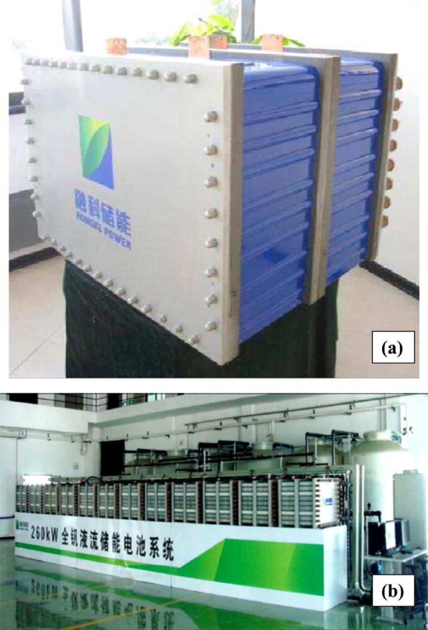
Figure 6. (Color online) 20kW VRB stack module developed by H. Zhang and co-workers at Dalian Institute of Chemical Physics and Dalian Rongke Power Co., Ltd (Ref. 231). Reproduced with kind permission from Prof. H. Zhang, Dalian Institute of Chemical Physics and Dalian Rongke Power Co., Ltd.
On the other hand, other developers are staying with smaller 5–10 kW stack module and integrating these into larger units off-site.64
In 2010, the US Department of Energy funded the demonstration of a 1 MW/8MWh vanadium redox battery for load levelling trials at the Painesville Municipal Power Station in Ohio233 and this project will include the development of 10–20 kW stacks for mass production.
Polysulphide-bromine
Like all redox flow cell chemistries that employ different elements in each half-cell, problems of cross contamination and solution chemistry maintenance were serious limitations for the polysulphide-bromine system that could not be addressed in small installations. For this reason, target applications were for very large utility scale projects ranging from 10 to 100 MW with 8–12 h of duration. The former Innogy Technologies using the trade name of Regenesys Ltd. developed the polysulphide-bromine redox battery for these target applications and began installation and commissioning of a 12 MW test facility at Little Barford, UK in the early 2000's.68, 233 Figure 7 shows the interior of the Little Barford facility showing the stream of 100 kW stacks developed by Innogy.
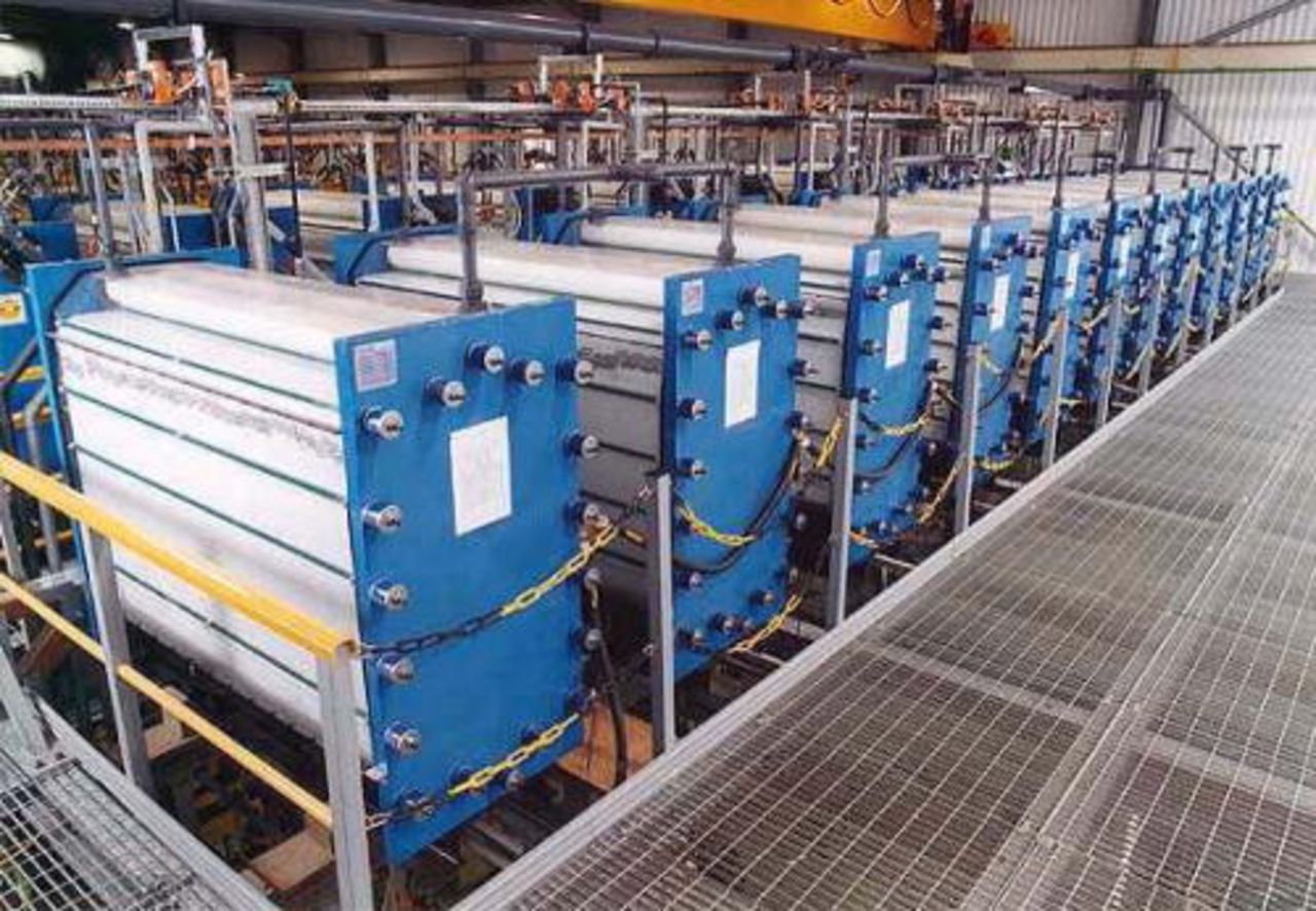
Figure 7. (Color online) Interior view of Innogy's 12 MW Regenesys plant at Little Barford, UK (Ref. 234). Figure reproduced with kind permission from the Department for Business, Innovation and Skills, Government of U.K.
The Regenesys technology had been tested at laboratory scale and was in the process of being proven at pilot plant scale. Development of the 100 kW XL module was started in parallel with full validation of the design concepts under test in the smaller reactors. Little Barford was the first demonstration of the Regenesys Technology at utility scale. The plant design was for 120 stack modules to operate with 1800 m3 of each electrolyte. The plants intended power output was to be 12MW (peak output of 15 MW) with an energy capacity of 120 MWh. The balancing system for the Regenesys Technology was in its early days of development and was unproven at plant scale. The original concept was to move the prototype balancing system being built at the OTEF test facility to Little Barford after it had been proven at scale. The OTEF balancing system encountered many problems however, as knowledge of the chemistry improved resulting in the Regenesys system becoming more complex than first envisaged. A number of other design and commissioning problems were also encountered and the plant was never properly commissioned or tested.
In 2002, Innogy was acquired by the German multi-utility RWE group of companies and under RWE Innogy's ownership the Regenesys energy storage technology was progressed to its first full-scale demonstration plant and into the commercialisation phase. In 2003, however, RWE decided that this did not fit with RWE's core business so a decision was made to sell the technology and business. In 2004 the Regenesys235 system was acquired by VRB power systems Inc. in Canada but no further development has been undertaken to date.
Unfortunately there are still several technical issues related to the commercialization of the polysulphide-bromine redox battery.236 Firstly, the preparation cost of carbon felt-based electrodes is considerably high, while the activated carbon-based electrode demonstrates energy efficiency less than 60%. In addition, the synthesis methods of sodium polysulfide from molten sodium and sulphur or H2S are very complex and expensive, so they are not suitable for large-scale production. Furthermore, the present commercialized cation exchange membrane does not show 100% cation selectivity, so anions can permeate through and cause crossover contamination during long term operation with the need for regular removal of sulphate from the positive half-cell solution and replenishment of sodium sulphide in the negative electrolyte.235
Zinc-bromine hybrid flow battery
Several projects were undertaken by ZBB Energy Corporation to evaluate the ability of the zinc-bromine system for solar energy storage.237 In the first project, a 50 kW rooftop PV system was installed in parallel with a 50 kW/100 kWh battery system at a commercial facility in New York. The second project was a 250 kW/500 kWh utility system that was installed on a remote utility circuit in New South Wales, Australia. This system was meant to complement an existing 20 kW PV concentrator system, support the remote line, and offer enhanced reliability. The battery was charged by the solar array during the day in order to provide reliable night time power to remote area property owners.237
Two other companies that are currently commercialising the zinc-bromine battery are Premium Power based in Massachusetts238 and Redflow based in Queensland Australia.239 Each have modular units that deliver up to 500 and 30 kWh of electricity storage respectively, and are designed as integrated power generation units complete with inverters and power conditioning equipment within a transportable trailer for easy installation. However, further scale up and full commercialization of the technology is yet to become a reality possibly due to the high cost of the bromine complexing agents and problems related to zinc deposition at the cathode during charge that can lead to dendrites and short-circuiting across the separator.
Flow Battery Limitations, Challenges and Future Research Opportunities
Despite major technological advances made in the field, the full commercial potential of flow battery technologies in both grid-scale stationary systems and in mobile applications will only be realised when a number of challenges are overcome, notably scale-up and optimization (with respect to flow geometries, state-of-charge sensors and automated control systems), improvement in electrolyte stability for a wider operating temperature range, development of electrode materials resistant to overcharge and mitigation of membrane degradation for low cost materials.147 To assist with this opimisation, a number of mathematical models have been developed to simulate the effect of cell geometry on cell performance and on oxygen and hydrogen evolution during the operation of the all-vanadium redox flow battery and measures to prevent gas production have also been suggested146–149 Further advanced modelling and simulation will assist in the development of advanced control systems that will allow remote operation of large VRB systems with automatic electrolyte rebalancing and capacity correction, while optimising electrolyte flow-rate to reduce pumping energy requirements and maximise overall energy efficiency.
Capital and cycle life costs reduction is also essential for widespread commercial uptake of all energy storage systems. The most expensive component of the all-vanadium redox battery has been reported to be the ionic exchange membrane and for this reason considerable research is being undertaken to develop low-cost alternatives. A modified perfluorinated membrane substrate material with a cost of less than one-third of the cost of Nafion was reported by Skyllas-Kazacos et al.79 and this material offers a suitable price structure for most applications. This new membrane was tested in 5–10 kW battery stacks and gave energy efficiency of 80%. Several research groups in China and the USA are currently developing novel low cost ion exchange membrane materials that promise to provide further cost reduction that will meet the cost structure requirements of a wider range of grid-scale applications.240–243 Any new membrane material will need to satisfy a number of requirements other than cost however, so the challenge is to develop novel membranes with high conductivity, low vanadium ion permeability, good chemical stability over a wide temperature range, oxidation resistance and resistance to fouling. Another critical property for membranes is their water transfer behaviour since this can lead to operational problems that require electrolyte level control and management. This is especially problematic when Nafion ion exchange membranes are employed in the VRB. Nafion exhibits high levels of swelling when immersed in aqueous electrolytes such as that of the VRB, causing an opening of the pores and excessive water transfer from one half-cell to the other during charge-discharge cycling.42 On the other hand, Nafion membranes are extremely stable in the highly oxidising V(V) electrolyte. Because of their high cost, however, Nafion membranes have not been employed in any of the VRB demonstration systems installed by Sumitomo and Kashima-Kita Power Corporation and alternative high performance anion exchange membranes have instead been used. Although not as expensive as Nafion, these anion exchange membranes are sensitive to electrolyte impurities, requiring the use of high purity vanadium electrolytes that add to the cost of the VRB. Further development of inexpensive, chemically stable membranes that are not subject to fouling by electrolyte impurities will therefore not only lower the cost of the stack, but will also allow lower purity vanadium oxide raw materials to be used in electrolyte productions, thereby enabling significant cost reduction of the entire system to be achieved.
Another critical component of the VRB is the electrode material that is traditionally carbon-based. Although a range of carbon and graphite felt materials is currently available for use in redox flow batteries with good energy efficiencies at current density ranges up to 100 mA/cm2, further improvements in electrode activity will allow operation at even higher current densities. The resultant increases in stack power density will mean that electrode areas and stack sizes can be reduced, allowing significant reductions in stack costs per kW power output. Early work by Skyllas-Kazacos and co-workers identified the important carbon surface functional groups that provide active sites for the vanadium reactions as well as treatment processes to enhance the surface concentration of these groups.24–26 Further work to increase effective surface area and electroactivity is currently underway in China and elsewhere244–246 and novel composite electrode materials are also expected to emerge in the future.
With regard to the bipolar electrode substrate, several groups have been developing carbon-filled polyolefin composite materials ("conducting plastics") that offer low cost, light weight, flexibility and ease of handling.46–48 For these materials to provide good conductivity for high current operation, however, the carbon felt needs to be heat bonded to the "conducting plastic" substrate to allow penetration of the carbon fibres through the surface to make contact with the carbon filler within the substrate. Although these heat bonded bipolar electrodes function well under normal operating conditions, long-term overcharge can cause delamination and increased electrode resistance. Good cell voltage control is therefore essential to avoid damage of the bipolar electrodes.
Some manufacturers are currently using polymer-filled expanded graphite board products,247 however, these materials tend to be very fragile and more expensive than the "conducting plastic" composites. As they tend to be very difficult to handle in large sizes, some stack developers have preferred to design and manufacture smaller stacks with electrode areas less than 1000 cm2 and output power less than 7 kW.248 Each scalable system integrates energy storage and power management in 175-kW modules up to 10 MW of capacity and 60 MWh of storage.248 With a focus on MW-scale grid storage applications, however, scale-up to 50 kW stack sizes will be important for ease of system assembly and integration. Both Kashima-Kita Electric Power Corporation and Sumitomo Electric Industries have successfully built and tested 40–50 kW stacks with demonstrated overall energy efficiencies of 80% and cycle life as high as 270,000 in large-scale all-vanadium battery field trials in Japan and elsewhere,78, 223 while Innogy successfully designed a 100 kW stack for the bromine-polysuphide Regenesys battery (see Fig. 7).249 In each case, however, conducting plastic composites were used as the bipolar electrode substrate material, allowing large electrode areas to be employed. The development of novel flexible, oxidation resistant bipolar electrode substrate materials will therefore allow the manufacture of large stacks that are resistant to overcharge with greater ease of operation.
Zhang recently describes the development of a conducting plastic bipolar electrode substrate with bulk resistance < 0.17 Ω cm, bending strength > 28 MPa, and corrosion resistance < 0.7 µA.cm−2 that is being used in the fabrication of 20 kW stacks.23 Dalian Rongke Power expect to manufacture these at a cost < US$15/m2 for a 10,000 m2/year production volume, however, long-term cycle performance and overcharge resistance has not been reported.231
Larger stack sizes require larger electrode areas as well as increased numbers of cells connected in series and parallel to produce the require kW power output. Flow batteries suffer from parasitic energy losses associated with the energy needed to power the pumps and the electrical leakage currents (shunt currents) that flow through the common electrolyte channels and manifolds.126 These parasitic losses typically consume 3–5% of the total energy stored, but can be minimized with optimal stack design. Increasing the cross-sectional area of the electrolyte channels and manifolds will reduce pumping energy losses; however, this will lead to increased leakage currents through the bipolar stack. As leakage currents increase with increasing number of cells in a stack, the practical limit for a bipolar stack is typically 20–30 cells, although up to 100 cell stacks have been achieved in certain flow cells with the use of shunt current interruption devices.126
Scale-up and shunt currents are a more difficult issue for zinc-bromine battery stack development however because of the potential for zinc dendrite formation and shorting.127 Uniform electrolyte and current distribution within each cell is critical for the prevention of dendrites and avoidance of hydrogen evolution during charging. This is much more difficult to achieve with higher electrode areas, so the tendency is to use smaller electrodes and complicated electrolyte flow distribution channel designs, but this cannot totally prevent zinc dendrites from forming at the negative electrode. To reduce the risk of shorting and possible fires therefore, it is essential to completely strip all of the plated zinc from the negative electrodes every few cycles, creating considerable operational problems.
Further stack modelling and simulation will assist in the optimal design of larger redox flow battery stacks for MW-scale applications, but a further issue that will need to be addressed is the potential problem of electrolyte leakage. Most early redox flow battery stack developers have used gaskets and O-rings to seal stack components, but this makes stack assembly cumbersome and labour intensive, while also yielding stacks that are prone to electrolyte leakage (both internal and external). This can be minimised by using thick and robust steel end-plates, but this adds considerable cost and makes the stacks extremely heavy and difficult to handle during installation.
The preferred solution to electrolyte leakage is the design and fabrication of welded stacks using vibration, infra-red and laser welding techniques as has already been applied to the manufacture of zinc-bromine flow batteries. Cellstrom has successfully produced a welded 2 kW stack module that is being integrated into their all-vanadium redox battery systems in Austria, but further work in scaling these processes for larger stack modules will be needed, along with automated stack assembly and welding equipment that will reduce labour costs and allow production in high labour cost countries.
Electrolyte maintenance is another important issue that will require further research and development in order to provide automated rebalancing and capacity restoration for extended cycle life. As with all aqueous systems, gassing side reactions in all flow batteries can occur during charging at high states-of-charge and this is mainly associated with hydrogen evolution at the negative electrode. Hydrogen evolution will cause a gradual drop in the V(II)/V(III) ratio in the negative half-cell electrolyte with each cycle, giving rise to an imbalance between the positive and negative half-cell electrolytes and a loss of capacity. While hydrogen evolution consumes a very small fraction of the total charging current in the vanadium redox battery, even a 1% current consumption can lead to 1% capacity loss per cycle. Similarly, air oxidation of V(II) in the negative half-cell solution will also reduce the V(II)/V(III) ratio relative to the V(V) to V(IV) ratio in the positive half-cell electrolyte, with a further loss of capacity that cannot be restored by simple electrolyte remixing. While this can be minimised by sealing the negative electrolyte reservoirs, capacity loss from gassing side reactions can only be restored by chemical or electrochemical rebalancing methods. Further research into state-of-charge monitoring methods for individual half-cell electrolytes will assist in the development of accurate state-of-charge sensors and rebalancing methods for automated electrolyte control systems. State-of-charge monitors based on electrolyte conductivity and UV-visible light absorbance have been described by Skyllas-Kazacos et al.52 and these can be further developed for specific flow cell electrolyte compositions.
RFBs offer a large number of advantages compared with fuel cells and other types of secondary batteries. They allow a degree of separation between power and energy components11 that provides great flexibility in designing a system to meet specific power and energy storage capacity requirements for each type of application.197 Compared to hydrogen fuel cells, RFBs have several advantages including low material cost, easier handling and storage of the liquid reactants compared to hydrogen and higher power density. But the energy density of current RFBs is significantly lower than that of fuel cells.74, 250, 251
Although the VRB has shown excellent cycle life and performance for most large-scale energy storage applications, the low solubility of the active vanadium species in the electrolyte of the all-vanadium redox battery limits its use to stationary systems mainly because of low energy density of the vanadium sulphate electrolyte (20–35 Wh/kg).79 As a consequence the vanadium- bromine system (with energy densities reaching 50 Wh/kg) was proposed and is being evaluated for possible applications in mobile systems such as electric buses and vans.107 Other redox couple combinations with higher energy density may be investigated, however, unless these can operate with a common element in both half-cells, diffusion of the active ions across the membrane will eventually lead to fully mixed solutions and a halving of the active ion concentration in each half-cell. A very encouraging recent report by researchers at Pacific Northwest National Laboratories in the USA may however hold the key to a high energy density all-vanadium battery that uses a 2.7 M vanadium electrolyte in a mixture of sulphuric acid and hydrochloric acid.252 This mixed acid electrolyte increases the solubility of each of the vanadium ions, allowing an almost 70% increase in energy density compared with the 1.6 M vanadium electrolyes currently used in commercial systems. This high energy density vanadium electrolyte has already been tested in small laboratory scale cells and has not only shown energy efficiencies as high as 87%, but importantly, no precipitation was observed at 0 and 50°C over 20 days, indicating a much higher temperature range than the original VRB using sulphuric acid alone. Further research and development of this mixed acid electrolyte system is expected to yield significant improvements in both energy density and temperature range of the VRB, expanding its practical applications beyond current stationary systems.
Another promising approach to increasing the energy density is the V-O2 hybrid redox fuel cell that totally eliminates the positive half-cell electrolyte by replacing it with a porous oxygen gas diffusion electrode. Such a system can potentially provide energy densities of 80–100 Wh/kg and will allow entry into the electric vehicle market and the possibility of mechanically refuelling by exchanging the spent negative half-cell electrolyte with freshly charged solution at special refuelling stations.22 The main challenge that will need to be addressed in the development of the V-O2 redox fuel cell will be the design and fabrication of low cost oxygen gas diffusion electrodes and membrane electrode assemblies that can operate in both charge and discharge modes. Promising results have already been reported by researchers at Twente University in The Netherlands, but further long-term testing is still needed to verify their cycle life and performance.218 With only a single electrolyte, the problem of diffusion of the active ions across the membrane is eliminated in the redox fuel cell, so the use of a single element in two half-cells is no longer a requirement to prevent cross contamination. This now opens the door to the use of any number of redox couples in the negative half-cell electrolyte, so a great opportunity is now available to develop new redox fuel cell chemistries that can be optimised for different applications and operating temperature ranges.
Another important issue with many energy storage technologies is raw materials costs and in the case of vanadium, dramatic price fluctuations in 2008 led to considerable investor uncertainty with regard to stable vanadium pentoxide supply and pricing for the all-vanadium redox battery.253, 254 While vanadium pentoxide prices have since returned at more realistic levels, it is critical that future prices and supply can be stabilised to avoid further uncertainty. In recent years a number of new vanadium resources have been identified in Canada, USA, Madagascar and Australia, with plans to set up considerable new production capacity in the next few years. While this will help to improve supply, other low cost sources of vanadium need to be explored for future cost reduction. These sources include spent catalysts, fly-ash and waste slags from steel production, but new processing methods need to be developed to allow the production of low cost electrolyte of the required purity for use in the VRB.
Electrolyte purity is a poorly understood area for electrolyte production however and very little is known about the effect of many potential impurities from different vanadium sources. Certain electrolyte impurities are known to deposit at the negative electrode during charging leading to increased hydrogen evolution.58 Others are known to cause fouling of certain membranes, while others are believed to cause precipitates to form in the porous felt electrode with resultant flow restriction.255 Membrane fouling is specific to the type of membrane used however and in some cases, combinations of impurities may be the cause of precipitation and fouling. In either case, very little information is available regarding maximum impurity levels, so VRB developers take the safe option of specifying very high vanadium pentoxide purities, thereby suffering the consequences of excessive vanadium prices. Enormous scope for cost reduction exists therefore from the use of lower purity vanadium pentoxide raw materials for electrolyte production, but this will require very extensive research to identify appropriate impurity levels for specific stack materials.
Even with current prices for vanadium pentoxide however, the cost structure for the vanadium redox battery is currently acceptable for most stationary energy storage applications and in cases where more than 4 h of storage capacity is required, costs estimates have shown that the VRB can deliver stored energy at close to half the cost of a corresponding lead-acid battery system,10 making it one of the most attractive energy storage technologies currently available for these applications. This comparison is illustrated in Fig. 8 and shows the comparative cost for each MWh of energy generated over the life of equivalent lead-acid and VRB storage systems, using a vanadium pentoxide price of $US5/lb (typical average price for period 2009–10).
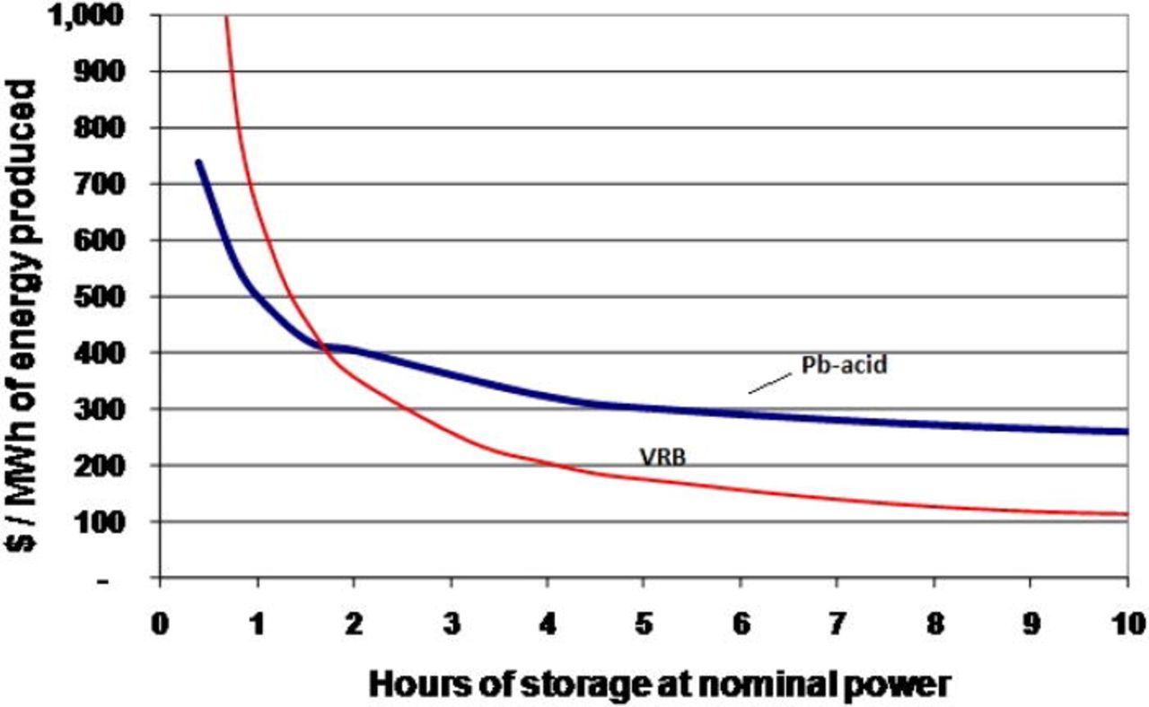
Figure 8. (Color online) Cost comparison of 5 kW/8 kWh lead-acid and VRB systems showing cost per MWh produced over life of each system. Assumption: US$1000/kW VRB stack cost (low volume production) and $US5/lb V2O5 (Ref. 10).
The cost calculations presented in Fig. 8 assumed low volume production of the VRB and a stack cost of US$1000/kW. With mass production, this is expected to decrease considerably however, with even lower capital and life cycle costs expected in the future. Furthermore, continuous research and development in the field of redox fuel cells may result in the development of commercial prototypes that could not only be used for stand-alone energy storage applications but also for mobile and traction services.
Conclusion
Despite their limitations, redox flow batteries have many technical benefits over other energy storage systems as well as an excellent combination of energy efficiency, capital cost and life cycle costs compared with other technologies. Cost is a major consideration when assessing the suitability of a particular storage technology for different applications. Cost calculations have shown that the cost per kWh of generated power over the expected life of a VRB system is almost half that of a corresponding lead-acid based system for storage capacities in excess of 3–4 h (depending on the assumed cost of vanadium). Other chemistries such as the Fe-Cr redox flow cell may offer even lower capital costs, but their annualised costs over the life of the system may be less favourable due to the inherent cross mixing of the different half-cell electrolytes that eventually reduces the capacity to half. Flow batteries are therefore uniquely suited to a range of applications that require more than 4 h of storage including:
- Storage for alternative sources of energy, including wind, solar (photovoltaic), wave
- Replacement of Remote Area Power Supply Systems (RAPSS) including diesel backup generators
- Load-leveling and peak shaving
- Storage for distributed power systems and Smart Grid applications
Several companies are now commercialising the all-vanadium redox battery in China, Europe and USA, while a recent revival in the iron-chromium redox flow battery was led by price instability for vanadium oxide products in 2007. While this is expected to be alleviated by new vanadium mines that will be opened over the next few years in Australia, Canada, China, USA and Madagascar, future recycling of vanadium waste products from steel slags, spent catalysts and fly-ash will provide opportunities for further cost reduction that will allow the VRB to enter other grid-scale energy storage markets.
Although the current VRB technology is already able to meet the performance, cycle life and cost structure for many stationary applications, the low energy density of existing redox flow battery technologies is limiting their potential application in electric vehicles that could otherwise benefit from the rapid refuelling capabilities of these systems. Further research into new flow battery electrolytes using organic solvents may lead to breakthroughs in energy density, however, this is likely to be associated with a higher cost penalty. The most promising area for energy density improvements therefore, will be in the further development of mixed acid electrolytes for the VRB and high performance hydrid redox fuel cell systems that employ a single electrolyte (typically in the negative half-cell) in combination with an oxygen gas diffusion electrode. The use of a single electrolyte eliminates the problem of cross contamination, allowing a wider range of redox couple chemistries with a wider operating temperature range to be employed. Advances in non-noble metal catalysts for the oxygen electrode and novel processes for leak-proof membrane electrode assemblies are urgently needed for the commercial implementation of such systems however, so vast opportunities are now available for new breakthroughs in this area that will lead to "refuelable" power systems for electric vehicles of the future.
Acknowledgments
The authors acknowledge the support of Dr. E. P. L. Roberts, Dr. R. A. W. Dryfe, Dr. C. H. Bae, Dr. N. Stevens, Dr. I. M. AlNashef, Prof. M. Azlan Hussain, and Dr. K. C. Namkung in the preparation of this document. The University of Malaya is gratefully acknowledged for providing full technical support.
List of Abbreviations
| DLRFC | Direct Liquid Redox Fuel Cell |
| EDTA | Ethylenediamine-tetraacetic acid |
| EMICl | Methylimidazolium |
| GDL | Gas Diffusion Layer |
| N-MPC | Nitrogen doped mesoporous carbon |
| [OC]OX | Electro-oxidized organic products (vanadium glyoxal RFB) |
| [OC]RE | Organic reductive raw material (vanadium glyoxal RFB) |
| OCP | Open Circuit Potential |
| OCV | Open-Circuit Voltage |
| PSB | Polysulphide-bromine |
| RFB | Redox Flow Battery |
| [Ru(bpy)3](BF4)2 | Tris(2,2'-bipyridine) ruthenium(II) tetrafluoroborate |
| SEM | Scanning Electron Microscope |
| SOC | State of Charge |
| TEA | triethanolamine |
| TEABF4 | Tetraethylammonium tetrafluoroborate |
| VOFC | Vanadium-Oxygen Redox Fuel Cell |
| VESS | Vanadium Energy Storage System |
| XRD | X-ray diffraction |
| y | year |