

Abstract
A critical review of classical and improved electrodes, electrocatalysts and reactors is provided. The principles governing the selection of electrochemical flow reactor or progression of a particular design for laboratory or pilot scale are reviewed integrating the principles of electrochemistry and electrochemical engineering with practical aspects. The required performance, ease of assembly, maintenance schedule and scale-up plans must be incorporated. Reactor designs can be enhanced by decorating their surfaces with nanostructured electrocatalysts. The simple parallel plate geometry design, often in modular, filter-press format, occupies a prominent position, both in the laboratory and in industry and may incorporates porous, 3D or structured electrode surfaces and bipolar electrical connections considering the reaction environment, especially potential- and current-distributions, uniformity of flow, mass transport rates, electrode activity, side reactions and current leakage. Specialised electrode geometries include capillary gap and thin film cells, rotating cylinder electrodes, 3-D porous electrodes, fluidised bed electrodes and bipolar trickle tower reactors. Applications span inorganic, organic electrosynthesis and environmental remediation. Recent developments in cell design: 3D printing, nanostructured, templating 3D porous electrodes, microchannel flow, combinatorial electrocatalyst studies, bioelectrodes and computational modelling. Figures of merit describing electrochemical reactor performance and their use are illustrated. Future research and development needs are suggested.
Export citation and abstract BibTeX RIS

This is an open access article distributed under the terms of the Creative Commons Attribution 4.0 License (CC BY, http://creativecommons.org/licenses/by/4.0/), which permits unrestricted reuse of the work in any medium, provided the original work is properly cited.
List of symbols
| Symbol | Meaning | Units |
|---|---|---|
| A | Geometrical electrode area | m2 |
| AE | Electrode area per unit electrode volume | m−1 |
| B | Breadth of rectangular flow channel | m |
| c | Reactant concentration | mol m−3 |
| cb | Reactant concentration in the bulk electrolyte | mol m−3 |
| de | Equivalent (hydraulic) diameter of a rectangular flow channel | m |
| D | Diffusion coefficient of an aqueous species | m2 s−1 |
| E | Electrode potential vs a reference electrode | V |

| Cell potential difference | V |
| Ee,cell | Equilibrium cell potential difference | V |
| E0 | Standard electrode potential | V |
| F | Faraday constant | C mol−1 |
| G | Molar Gibbs free energy | J mol−1 |
| I | Current | A |
| IL | Limiting current due to convective-diffusion | A |
| j | Current density | A m−2 |
| j0 | Exchange current density | A m−2 |
| k | First order apparent rate constant | s−1 |
| km | Mass transfer coefficient | m s−1 |
| L | Length of rectangular flow channel in the direction of flow | m |
| M | Molar mass | g mol−1 |
| n | Amount of a species | mol |
| q | Electrical charge | C |
| Q | Volumetric flow rate of electrolyte | m3 s−1 |
| R | Electrical resistance | ohm |
| s | Space velocity | s−1 |
| S | Separation between the electrode and membrane (divided reactor) or between the electrodes (undivided reactor) | m |
| t | Time | s |
| T | Temperature | K |
| v | Mean linear flow velocity of electrolyte | m s−1 |
| V | Volume of reactor | m3 |
| VE | Overall volume of electrode | m3 |
| VR | Volume of electrolyte in the reactor | m3 |
| VT | Volume of electrolyte in the tank | m3 |
| w | Catalyst mass loading | g |
| x | Distance along electrode | m |
| XA | Fractional conversion of reactant | Dimensionless |
| z | Electron stoichiometry | Dimensionless |
Greek
| Symbol | Meaning | Units |
|---|---|---|
| α | Charge transfer coefficient | Dimensionless |
| ε | Surface roughness of electrode | m |
| γ | Limiting current enhancement factor compared to a smooth surface | Dimensionless |
| η | Overpotential (η = E−Ee ) | V |
| ν | Kinematic viscosity of the electrolyte | m2 s−1 |
| ω | Velocity exponent | Dimensionless |
| ϕ | Current efficiency | Dimensionless |
| ρ | Electrical resistivity | ohm m |
| ρST | Space time yield | mol m−3 s−1 |
| τT | Mean residence time in the tank (τT = VT /Q) | s |
| Subscripts | |
| a | Anode |
| act | Activation (under charge transfer control) |
| c | Cathode |
| conc | Concentration (under mass transfer control) |
| cell | Cell |
| e | At equilibrium |
| E | Electrode |
| N | Normalised |
| R | Reactor |
| T | Tank (reservoir) |
| (0) | At time zero |
| (t) | At time t |
| Dimensionless groups | |
| Le | Dimensionless length (Le = ε/de ) |
| Re | Reynolds number (Re = vde /ν) |
| Sc | Schmidt number (Sc = ν/D) |
| Sh | Sherwood number (Sh = km de /D) |
Electrosynthesis has a proud history, which ranges from the routine, tonnage scale production of chlor-alkali chemicals and electrowinning of metals to the small scale realisation of speciality products, such as pharmaceutical and fine chemicals, metal alloys, composites, semiconductors and superconductors. 1–4 Proponents would highlight the convenience of electrochemistry, its ease of control, the environmentally clean nature of the electron as a reagent and the ability to produce powerful species, in situ, under near ambient conditions. Antagonists might balance these features against limitations, including the speciality nature of the discipline and their lack of training and support in practical electrochemistry and electrochemical engineering together with the shortage of literature on successful case studies of modern electrosynthesis at an industrial scale. The design, operation and scale-up of electrochemical cells remains a critical challenge to the continued development and diversification of electrosynthesis.
The design of electrochemical cells has often been focussed on glass cells for laboratory benchtop use, the services of a skilled glassblower being essential in sealing electrodes in glass and making microporous gas bubbling/cell dividing frits or flanges to accommodate ion exchange membranes. 5 The motivation for glass beaker cell use is clear, as they are easy to assemble and clean, and sample exchange for manual batch analysis is facile. However, reaction conditions are often poorly reproducible, especially when attempting to accelerate reactions rates through magnetic stirrer bars or gas bubbling.
This has led to a large proportion of electrochemical synthesis works moving away from beaker cells and into more specialist reactors, with flow fields, turbulence promotors and fixed electrode geometry and position greatly enhancing reproducibility and turnover rates. The danger here is that all electrosynthesis studies are carried out in the same reactor; the different reaction mechanisms require vastly different reaction environments in order to optimise reaction rate, charge efficiency and product conversion. Often these three parameters cannot all be maximised, and so reactor design must focus on reaching a compromise reaction profile.
This review provides an overview of the key reactor designs employed for electrochemical synthesis, covering initial bench-top proof of concept scale up to larger industrial standard reactors. The merits of various reactor designs are discussed in terms of practical applications, along with methods of improving their output via the complementary design of 3D electrode structures, electrolyte flow profiles and mass transport distribution.
Principles of Electrochemical Reactor Design
General considerations
Electrochemical reactors can be inherently complex and contain several controls and sensors for specific electrosynthesis processes or can also be a simpler generic design suitable for a screening process at small scale. The final design should comply with a number of essential characteristics 6 that include:
- 1.Moderate capital and running costs, require low cost components, a low cell potential difference and a low pressure drop over the entire cell including the inlet and outlet flow manifolds for the electrolyte; where possible, an undivided reactor will simplify engineering design and result in lower capital and running costs.
- 2.Convenience and reliability, adequate design, installation, operation and maintenance and monitoring procedures.
- 3.Appropriate facilities to control and monitor concentration, potential, current density and adequate mass transport regime to provide and remove reactants and products respectively, via suitable flow distributions.
- 4.Simplicity and versatility are perhaps the least quantified and most overlooked, yet perhaps the most important, factors for achieving an elegant and long-lasting design to attract users.
- 5.Provision for future developments by designing a modular configuration that facilitates scale-up by adding unit cells or by increasing the size of each unit.
Industrial applications of electrochemical reactors include the production and conversion of chemicals e.g. the chlor-alkali process, 7 aluminium metal production 1 and adiponitrile 8 among other important applications, such as energy conversion and storage. 9 The reactors also offer the opportunity to use electrochemical techniques for the investigation of electrode processes involving mass transfer, charge transfer and influence of cell hydrodynamics which is typically carried out in small electrochemical cells at laboratory scale.
In electrosynthesis, the electrolyte is often single phase, the reactant(s) and/or products being sufficiently soluble to avoid undue mass transport restrictions. In order to minimise ohmic drop in the electrolyte, a small interelectrode gap may be used and gas hold-up should be avoided by using a sufficient flow velocity. It is also common to add a concentrated indifferent electrolyte, the ions carrying most of the migration current between the electrodes. The counter electrode reaction must also be considered as gas evolution or corrosion may unbalance concentration or pH and introduce evolved gas as a second phase.
In a two-phase liquid-liquid electrolyte, a phase transfer reagent may be needed to facilitate reactant or product transfer between the phases. In an organic-aqueous electrolyte, quaternary ammonium salts or surfactants have often been used. In special cases, the electrolyte may be a solid-liquid emulsion or suspension. Composite electrodeposition of materials utilises an agitated slurry of solid particles or a sol to deposit materials by a combination of electrophoresis, convective-diffusion and electrodeposition. 10
Cell voltage and its components
When current flows through an electrolytic cell, the cell voltage (U) can be expressed as:

The first term on the right hand side is set by selecting the electrode reactions and their thermodynamics, Ue being directly related to the Gibbs free energy change (ΔGcell ) for the cell reaction:

where F is Faraday's constant and z is the electron stoichiometry. Ecell is the equilibrium cell potential difference, defined as the difference between the anode and cathode potentials (Ee a —Ee c ). The second term in Eq. 1 is governed by the electrode kinetics and mass transport to and from the electrodes, as determined by the electrode overpotential (η). The third term represents ohmic losses, related to the current passed (I) and electrical resistance (R). Expanding the expression gives:
The modulus of values is taken to allow for negative cathode current values indicating a reduction. By convention, positive overpotentials give rise to oxidation currents and negative overpotentials give rise to reduction currents. For (non-spontaneous) electrolytic processes, Eqs. 1 and 3 predict that the cell potential difference, U is positive and becomes larger with increasing current density.
ηc,act and ηa,act are the charge transfer overpotentials at the cathode and anode, respectively, representing kinetic charge transfer limitations which dominate at low current densities. Such overpotentials can be minimised using the appropriate catalysts for a particular reaction and operating at a higher temperature. The concentration overpotentials under convective-diffusion terms, ηc,conc and ηa,conc are important at high current densities. These overpotentials cause a potential loss due to mass transport limitations of electroactive species reaching, or leaving, the electrode surface and can be minimised employing high surface area electrodes, high mass transport flow regimes or turbulence promoters. The IR term is the sum of all electrical resistances across the reactor and the electrodes as well as that of the electronic connections. These include all ohmic drops in the system, i.e. the external electrical contacts, the current collectors and electrodes, electrolyte(s) and membrane. Minimisation of these resistances lowers energy loss and can be achieved by: (a) reducing the overpotentials of the reactions at the electrodes using a suitable catalyst and (b) reducing the resistances through the membrane, across the electrolyte(s) and through the electrodes. For an electrosynthesis cell, minimising all potential losses in the reactor minimises the cell voltage required.
Electrode kinetics
Electrode potential is "the double-edged sword of electrochemical technology." If the potential is well controlled, yield, selectivity and reaction rate can be high, but when the potential distribution is poor, rate, purity and yield can all suffer. It is important to monitor electrode potential not just in laboratory cells but in pilot and full scale electrochemical reactors, both to relate performance back to polarisation behaviour and act as a powerful diagnostic probe for cell condition monitoring. Electrosynthesis cells should always be provided with facilities for incorporating a robust reference probe. 11
For an electrosynthesis cell, minimising all potential losses in the reactor minimises the cell voltage required.
The overall rate of an electrode process can be described by Faraday's laws of electrolysis, which may be written as a space-time yield, ρST , i.e., the amount of product per unit reactor volume per unit time:

where V is the reactor volume, VR
is the electrolyte volume, n is the amount of a species and t is the elapsed time. The current efficiency (or charge yield),  allows for a fraction of the current being used in secondary reactions. The common units of mol m−3 h−1 can be obtained on multiplying the right-hand side by 3600. When comparing electrode performance it is often useful discuss in terms of a normalised current, either the current density (j) by normalising current against the electrode area (A):

or a specific current (Iw ) by normalising current against catalyst mass loading (w):

Normalisation is usually against the geometric area rather than the electrochemically active area, rougher or more porous electrodes being able to support much larger current densities. 12
Figures of merit
Figures of merit (FOM) for electrochemical reactors are convenient normalised criteria of performance for the diverse range of electrochemical reactors that exist for different applications. The figures of merit are useful to compare different reactors and help the selection for a particular purpose. In addition the selection should be based on safety and reliability characteristics as well as the most convenient operational mode. The most common figures of merit are presented in Table I.
Table I. Typical figures of merit used to describe electrochemical reactor performance. 1,13
| FOM | Expression | Observations |
|---|---|---|
| Fractional conversion |
| n(0) initial amount |
| n(t) amount at time t | ||
| Current efficiency |
| qproduct, charge passed to produce product |
| q, total charge | ||
| M, molar mass | ||
| Selectivity |

| nproduct, amount of product |
| ntotal amount of all species produced | ||
| Specific energy consumption for electrolysis |

| |
| Energy efficiency during electrolysis |

| |
| Active electrode area per unit volume |

| |
| Mass transport coefficient |

| IL, mass transport limiting current |
| c concentration of the electroactive species | ||
| Mass transport coefficient associated to the electroactive area |
 or or 
| AE, electrode area per unit electrode volume |
| VE, electrode volume | ||
| Space-time |

| Q, volumetric flow rate. |
| Space-velocity |

| |
| Space-time yield |
| |
| Normalised space-time velocity |
| |
| Normalised space time yield |
|
It is also important to evaluate the suitability of an electrochemical rector and the initial investment cost and the operational cost, including the costs of electrolysis and moving parts, i.e. electrolyte pumping or electrode rotation. The evaluation should also consider the life time of all the components which cost could increase the initial investment and running of the process. A careful selection of suitable materials needs to consider lifetime, sustainability, recycling and environmental disposal.
Figures of merit are extensively used to compare the performance of electrochemical reactors employed for waste water treatment containing phenolic compounds, 14 ground water treatment, 15 waste water from the petrochemical industry 16 and metal recovery or remediation of waters containing phenolic compounds.
Electrochemical reactors require high current density, energy density and energy efficiency which can only be achieved by the appropriate selection of electroactive species and selective catalyst to avoid parasitic reactions as well as comparative performance to quantify their capability. The explicit mathematical figures of merit listed in Table I are essential to make such comparisons specially those based on the normalisation considering the stack volume and the electrolyte volume
In the case of electrosynthesis of soluble redox mediators in bipolar filterpress cells, many engineering aspects of cell design are in common with that of redox flow batteries, which have been treated in extensive reviews. 17–19
Practical features
The most basic electrochemical testing can be performed in simple glass beakers with anodes and cathodes immersed in electrolyte. Adding glass-blown flanges facilitates anodic and cathodic separation via a membrane or porous separator. As reactors are scaled up and flow is introduced, more complex reactor designs are usually assembled from a series of stacked components, comprising of electrode plates, gaskets, separators and housings. Practical cells usually require even compression of flow and electrode compartments to ensure adequate sealing. It is common to facilitate uniform compression by using rigid (often insulated steel) end plates. Well-spaced threaded (often stainless steel) fastenings apply compression through the cell, as seen in commercial cells such as the Electrocell, 1 the FM01-LC electrolyser 20 and the Microflow cell. 21 Tools such as wrenches (and especially torque wrenches) are rarely found in synthesis laboratories and manual, thumb screws are convenient and used in several designs. In the versatile laboratory cell, one end plate is fixed in a frame, the other being tightened and relaxed via a single thumb screw. 22 It is useful to have the inlet and outlet flow tube connectors mounted on an end plate and able to be tightened and relaxed manually, precluding the need for hand tools. Thumb screws are convenient and their use has been continued in contemporary designs, such as the C-Flow cell 21 shown in Fig. 1.
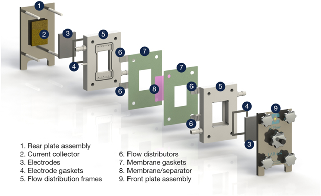
Figure 1. The C-Flow® Lab 5 × 5 laboratory-scale flow cell. The electrodes have a projected electrode area of 25 cm2 with a typical electrolyte linear flow velocity of 1–10 cm s−1. Figure courtesy of C-Tech Innovation Ltd.
Download figure:
Standard image High-resolution imageElectrochemical cell components are prime candidates for 3D printing, either from polymer materials or stainless steel depending on whether the component should be electrically insulating or should function as a current collector. The same technologies can be used to fabricate the electrodes themselves, or conductive steel, Ni or Ti units can allow insertion and removal of anode and cathode plates. Of course, 3D printing is not a necessity; stacked components with machined pores and channels can be arranged to give relatively complex internal structures providing an adequate seal is obtained. Stacked cell designs require adequate separation between anode and cathode to prevent electrical short circuits or product crossover. Electrical separation can be achieved with porous polymer meshes or crushed glass frits, or chemical separation requires ion exchange membranes.
The choice of solvent and electrolyte must consider the stability of reaction intermediates for the full electrochemical mechanism, and also whether sufficient overpotential can be applied within the solvent window. Aqueous systems are cost effective and simple to work with, although the solvent window of water is narrow compared to organic media or ionic liquids. Many electrochemical systems show a strong pH dependence and the requirement for proton transfers often necessitates and aqueous electrolyte. It is also important to consider surface interactions between electrolyte ions and the catalyst surface. Strongly adsorbing species can block catalyst sites, which can reduce the rate of reaction or have drastic influence on product selectivity. 23
Organic electrolytes and room temperature ionic liquids give a wider solvent window than aqueous equivalents, and allow reactions through intermediate species that would be oxidised in an aqueous environment. 24 Ionic liquids are able to stabilise high energy radical intermediates for organic electrochemical synthesis. 25 Proton transfer in organic or ionic liquid media can be facilitated by including low concentrations of water either in the liquid phase or as a humidified gas stream. This has been successfully achieved for CO2 reduction in ionic liquids, although so far the limited water availability has only given access to 2e– formate or CO products and cannot reach desirable C2 species such as ethylene or ethanol. 26 Ionic liquids are especially desirable from an environmental perspective as they can be recycled via solvent extraction to be reused for further electrochemical synthesis. Since their environmental standing is dependent on extraction and recycling and their viscosity gives slow mass transport rates, their use is currently too costly for industrial scale-up. 27
Decisions During Reactor Selection or Design
Strategic decisions
In the 1960s, electrochemical engineering principles were increasingly applied to cell design and a diverse range of electrode and cell geometries developed for laboratory and pilot scale use in the 1970s. 6,28–31 Many of these designs, particularly packed, 32 fluidised and moving beds, were primarily intended for metal ion removal from dilute waste liquors 33 although uses in synthesis have been considered. Such developments and their industrial applications have been reviewed. 1,34
It is generally accepted that depending on the applications the electrochemical reactor has to be designed for the particular process in order to optimise the figures of merit such as conversion, current efficiency, selectivity, energy consumption and efficiency, cell voltage, electroactive area, mass transport and space tie and space velocity. Selectivity and conversion are more important than energy efficiency in electroplating and organic electrochemistry respectively, whereas energy efficiency is more important for redox flow batteries and industrial production of, e.g., adiponitrile, aluminium and chlor-alkali.
Independently of the application of the electrochemical reactors, several principles need to be followed in order to provide an optimised design. Some basic strategic decisions for constructing an electrochemical reactor include considerations that could be conflicting and the decision on what aspects to favour on detrimental to others has to be realised on their importance for the process. Some of these considerations include: a) simplicity in order to reduce cost, b) reliability for routine operations, cleaning and inspection, c) integration so the reactor aligns with existing production processes, d) reaction engineering to optimise selectivity, production, current and potential distribution, mass transport, electroactive area, interelectrode gap and low overpotentials, 35 e) operational cost having reliable and low cost cell components such as electrolyte and separator, if needed, f) minimisation of mechanical devices such as electrolyte pumps or electrode agitation and g) low pressure drop over the reactor.
Other strategic decisions are whether the process is batch or continuous operation and how the products will be removed from the reactor, depending on their physical characteristics. Gas products are typically vented at lower pressure or displace them with an inert gas or via a gas liquid separation unit. Liquid and solid products can be separated by flotation, settlement, or solvent extraction.
Figure 2 offers a simple strategy to aid selection or development of a particular electrode geometry and cell design. 6 When used retrospectively, this approach helps to rationalise diverse cell designs by considering their major characteristics. Alternatively, Fig. 2 can aid the selection of an available cell design. The benefits and compromises involved in making such a choices can be briefly considered.
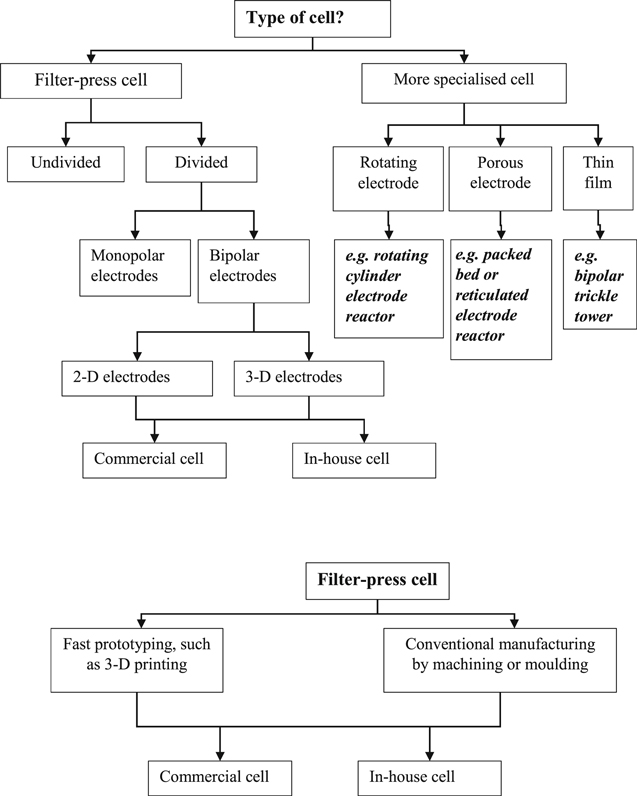
Figure 2. A decision tree regarding cell features. 6
Download figure:
Standard image High-resolution imageDivided and undivided reactors
One of the first decisions in reactor design whether the reactor operates with separated cathodic and anodic electrolyte compartments by an ion exchange membrane, a porous separator or a single electrolyte compartment. The single compartment design is simpler and avoids the cost of the ion exchange membrane and the gaskets and fittings in the electrolyte required to fit the separator (Fig. 3). Divided reactors avoid mixing of catholyte and anolyte electrolytes which prevents product consumption or unwanted side reactions occurring at the opposite electrode. Although small inter-electrode distances can be realised with a separator, as with the 2 mm inter-electrode gap of the bromide polysulfide redox flow battery, 9 divided reactors also increase the ionic resistance due to the separator.

Figure 3. Schematic diagrams for a number of commonly employed laboratory scale electrochemical cells. Solid arrows indicate the direction of solution flow. Dashed lines indicate a porous separator or ion conductive membrane. Electrolytes in A-C may also be mixed through additional means such as magnetic stirrers or gas bubbling. (A) Undivided beaker cell, (B) Beaker cell with the anode confined in a porous chamber, (C) Divided H-Cell with a membrane separator, (D) Undivided flow cell with an electrolyte reservoir and circulating electrolyte pump. (E) Divided flow cell with separate anolyte and catholyte reservoirs on either side of a microporous membrane separator. 36
Download figure:
Standard image High-resolution imageCell designs without a membrane or separator have a smaller ohmic resistance as the impedance caused by a separator is absent and are capable of wider range of flow profiles. Furthermore, degradation and material cost for membranes do not have to be considered. For instance, the membrane in PEM fuel cells accounts to 24% of the total cost. Membrane-less designs can have porous electrodes, allowing flow through, fluidised bed electrodes, gas diffusion electrodes and redox mediators.
The selection of a divided or undivided reactor is important in the electrochemical water treatment methods to deplete anthropogenic persistent organic pollutants. Typically, the main direct and mediated oxidation (via highly oxidising radicals) occurs in the anode compartment, in which case a divided reactor will be required. In some instances, a two-stage remediation process involves the preparation of the oxidants (e.g., persulfates, perphosphates, percarbonates) in the reactor which are then added to the wastewater. In a divided reactor, direct and mediated oxidation can be carried out at the anode where single, and mixtures of, highly oxidising species can be generated at a high current efficiency.
A more synergetic process is the combination of the anodic and cathodic processes to increase the degradation efficiency, in which case an undivided reactor may be used. For example, in order to increase the oxidation power of cathodically generated H2O2, an undivided reactor will allow the hydrogen peroxide to couple with other reactions such as Electro-Fenton based processes. 37 It can be argued that the efficiency will decrease due to the decomposition of H2O2 at the anode a trade-off exists between the increase of cell potential due to the separator and the effectiveness in the depletion of the organic pollutant by the concerted anodic/cathodic treatment when using undivided cells. One example of the use of divided and undivided reactors was reported by Ochoa-Chavez et al. 38 who showed small difference in the degradation of 5-fluoro-1H-pyrimidine-2,4-dione (5-FU) with 75% and 77% for undivided and divided reactor, respectively using 50 mg l−1 FU at 150 A m−2, 13 l h−1 and 6 h of electrolysis.
The use of divided electrochemical flow reactors has been widely explored in inorganic process such as the chlor-alkali and in energy generation and storage devices like fuel cells and redox flow batteries. They increase energy conversion efficiency by preventing parasitic reactions and can reduce energy losses by separate optimisation of the anodic and cathode reactions. Their use in organic electrosynthesis and the effect of the organic material on the ion exchange membranes is poorly explored. The issue becomes more complex when deciding whether a cationic (CEM) or anionic exchange membrane (AEM) can be used as the selection of the membrane should maintain the material balance of the anodic and cathodic reactions in order to maintain the neutrality and avoid drastic pH changes in both electrolyte compartments.
CEMs and AEMs are designed to conduct cations and anions respectively, in theory CEM repel neutral molecules and anions while AEM repel neutral molecules and cations. Nafion® is the most commonly used CEM due to its high ionic conductivity and chemical resistance due to a robust fluorocarbon backbone with sulfonic groups as ion exchange sites; other membranes based on sulfonated styrenes, polyimides, and arylene ethers, are less stable. On the other hand, AEM are based on fluorinated hydrocarbons, poly(ketones), poly(ethers), and poly(ether ketones) with imidazolium, quaternary amine or phosphonium as the anion-exchange groups but these are chemical less stable than CEM. A clear example of the convenience of using anion membranes is the borohydride fuel cell 39 ; although CEMs have good resistance in the alkaline environment, they produce a chemical imbalance when OH– is consumed and not replaced from the catholyte compartment, making the anolyte more acidic in the long term. AEMs keep the chemical balance by replacing the OH–; unfortunately, most anionic membranes are unstable in alkaline environments.
Bipolar membranes (BPMs) offer an alternative structure to address the challenges limitations of AEMs and CEMs. A cationic and anionic layer are combined to give a two-layer structure, preventing product crossover while still permitting the charge to be carried by H+ and OH–. There are two modes of operation determined by the reaction at the cationic-anionic phase interface; facing the cationic side to the cathode generates H+ and OH– by water electrolysis, whereas facing it to the anode drives the opposite reaction. 40 Care still must be taken, as some undesired ion crossover may still occur 41 and BPMs can suffer from delamination and dehydration, particularly at large current densities. 42
Monopolar and bipolar electrical connections to electrodes
The electrochemical characteristics of a system are typically determined in a single three-electrode laboratory scale cells of ≈100 cm3 volume with cell voltages of approx. 1–2 V. If the system is scaled up to a large number of electrochemical cells it might need the application of larger cell voltages. Several single electrochemical cells can be put together to increase the area, thus the production capacity, and they can be arranged as a monopolar connection as is shown in Fig. 4A, where each electrode is either positive or negative. This arrangement maintains the cell voltage of one individual cell but is able to generate high currents. In order to increase the voltage, the monopolar connected cells can be arranged in series, see Fig. 4B. Another strategy consists of connecting the cells in a bipolar configuration as is shown in Fig. 4C, which is commonly used in electrosynthesis cells, fuel cells and redox flow batteries. In this arrangement the voltage depends on the number of cells. The electrodes acquire a different charge on each side, driving the oxidation reaction on one side and the reduction reaction on the other simultaneously.
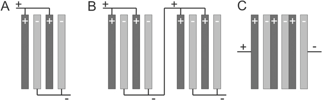
Figure 4. (A) monopolar electrode connections, (B) monopolar cell stacks connected in electrical series, (C) bipolar electrodes. 34
Download figure:
Standard image High-resolution imageBipolar electrode connections allow more compact cells than monopolar connections because there are no electrical cables connecting each electrode. Both monopolar and bipolar configurations are found in cells designs that can be easily scaled-up to industrial production. 23,43 The bipolar electrodes typically contain an electronic conductive flat plate in the centre which has two purposes, a barrier for the positive and negative electrolytes and as an electronic connection to transfer electrons. In redox flow batteries and fuel cells the core electronic conductive is a graphite plate. 44 In fuel cells, the bipolar plates also carry the gases to and from the gas diffusion electrodes, i.e. they act as flow fields.
Porous, 3-D electrode structures
Porous materials offer large surface electrode areas and are typically used in electrochemical flow reactors, where they are most effective, for a variety of applications such as electrosynthesis, oxidation of organic materials in wastewater, metal recovery, energy storage and generation. 45–48 They can be arranged in two configurations; flow-through 49 and flow-by, 43 where the current and the electrolyte flow run parallel and perpendicular to each other, respectively. In both configurations the electrodes face each other in order to ensure a uniform current distribution. However, although the intricate structure of the 3D electrodes contributes to increase the mass transport of electroactive species towards their surface, it also causes different resistance values between opposite points of the electrodes. This geometrical differences causes changes in the potential and current distribution on the electrodes affecting their performance. The current distribution can be divided between primary, which depends on the geometry, secondary that depends on kinetic factors and tertiary which depends on the concentration. 30
The geometry of the three dimensional electrodes are also able to increase the space-time yield of electrochemical reactors by providing effective use of the reactor volume and increase their efficiency compared to 2D electrodes. 50 In flow reactors, the mass transport can be controlled and measured and correlated to the pressure drop and flow dispersion to evaluate the overall cost–benefit of the electrodes. The most preferred techniques to characterise 3D electrodes include the limiting current and conversion rate measurements because they are fast and convenient. Typical materials and configurations include carbon felt, 51 foam 52 and reticulated vitreous carbon (RVC) 53 as a cost-effective porous electrode with large surface area and porosity. Metal mesh, 54 felt 55 and foam 56 electrodes have also been prepared from materials such as nickel, titanium and copper (Fig. 5).
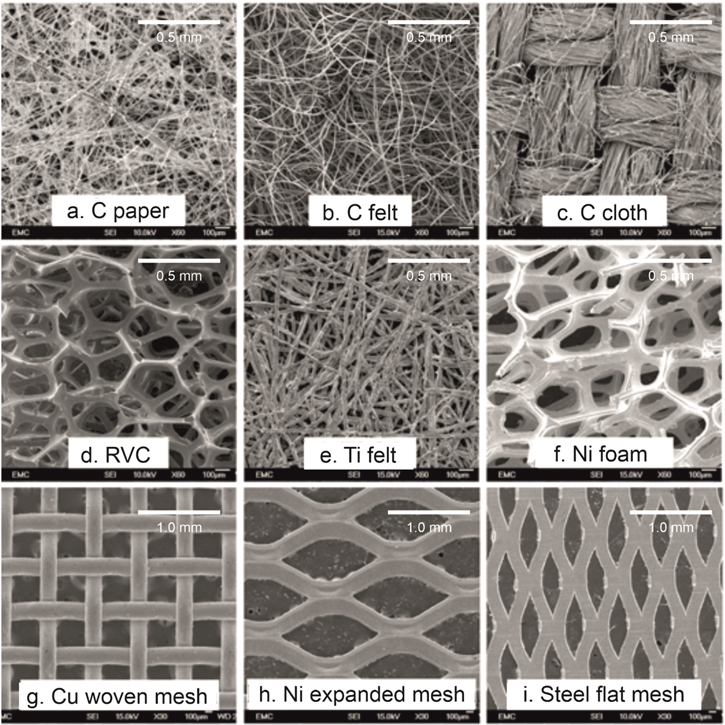
Figure 5. Commonly employed 3D electrode scaffolds in electrochemical reactors, offering a great range in porosity, tortuosity and active surface area. Figure adapted from Ref. 57 available under Creative Commons (CC-BY) license, published on behalf of The Electrochemical Society by IOP Publishing Limited 2020.
Download figure:
Standard image High-resolution imageThe importance of 3D architectures has been emphasised by the properties observed when structures such as nanorods, nanospheres, nanoonions, networks of nanowires and nanoflowers, microflowers, nanowalls and hierarchical structures are manufactured on flat plate electrodes or inside already three dimensional electrodes. 58,59 Indeed, the electrochemical properties of 3D substrates can be improved and tailored by surface treatment or deposition of catalyst for a particular reaction. A typical example is the electrodepositon of Pt on titanium plate, felt or meshes. 60 One of the disadvantages of 3D electrodes is that they can present uneven current and potential distributions, resulting in asymmetric electrodeposition of catalyst particles as well as uneven final operations. It is necessary to establish the optimal electrode thickness to ensure that all the covered electrode surface is electrochemically active. 61 In thicker electrodes not all the surface of the 3D electrode is at the same potential and the distribution of the catalyst might not be homogeneous. Rather than use electrodeposition, catalyst materials can be added via electroless deposition or dip coating, which can be monitored via the open circuit potential. However, there is still the possibility that parts of the electrode are inactive due to the potential distribution if the electrode is too thick or if the concentration of the electroactive species is too low.
The determination of the optimal thickness of 3D electrodes can be obtained by mathematical simulation. For example Nava et al. 62 suggested that, in conductive porous electrodes, a unidirectional potential distribution under limiting current conditions can be modelled assuming plug-flow conditions and that in excess of supporting electrolyte, the conductivity changes during electrolysis are negligible. The model assumes that only the concentration decay of the electroactive species within the electrode is responsible for the potential distribution. More complex models assume that the electrolyte flow rate and electrode thickness determine the ohmic drop inside the porous electrode. In practice, the potential difference between the porous electrode surface and the solution should not be too large in order to ensure that hydrogen and oxygen evolution do not occur during reduction and oxidation, respectively.
Examples of Reactor Designs and their Performance
Vertical plates in a stirred beaker
The number of commonly employed reactor designs is extremely broad, depending on the desired reaction profile and scale (Fig. 6). Vertical plate electrodes in a stirred beaker are a staple in electrochemical laboratories thanks to their simple design, ease of assembly and broad application scope. Basic reactor designs hold the anode and cathode within the same beaker. Small modifications can separate these via an ion-exchange membrane in an H-cell configuration. 63 Both can be operated in terms of cell potential, or a reference electrode can be inserted into one compartment near to either the anode or cathode, defined then as the working electrode. As well as a popular choice for electrochemical teaching laboratories, the ability to rapidly replace electrodes, electrolytes and membranes make these cells idea for batch testing and proof of concept work in catalysis, redox flow batteries and electrochemical synthesis. 64
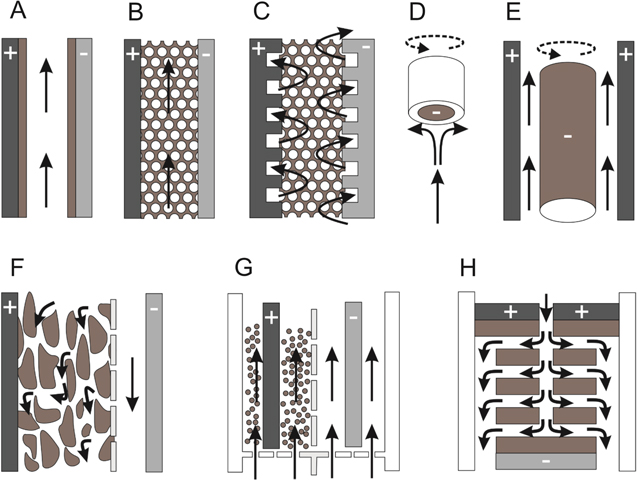
Figure 6. Schematic diagrams of common electrode and reactor reactors. Grey shading indicates a driving electrode, brown a catalytically active material and white an insulating surround or membrane. Solid arrows show the electrolyte flow direction, dashed arrows show component rotation: (A) parallel plate flow-by electrode, (B) parallel plate flow through electrode, (C) interdigitated flow through electrode, (D) rotating disc electrode, (E) rotating cylinder electrode, (F) trickle bed electrode, (G) fluidised bed reactor, (H) thin film bipolar electrode disc stack. 1
Download figure:
Standard image High-resolution imageAlthough convenient for initial experimentation, the simplicity of the cell design limits the applicability of the stirred beaker for up-scaling. The use of magnetic stirrer bars gives a limited mass transport range with poor reproducibility, due to the variable stirrer position, non-standardized stirrer bar size and interaction of stirred solution with the beaker wall. 65 Up-scaling efforts must proceed via intermediate-scaled reactors with volumes on the order of m3, which offer a compromise in easy of assembly and varying parameters against applicability towards up-scaling to industrial specifications. Up-scaling focuses on incorporating multiple anodes and cathodes in the same tank, either unseparated or by confining all of one electrode (e.g., all the anodes) in ionic membrane compartments, which are submerged in a reactor tank containing unconfined cathodes. 1 Such designs are employed for large scale electrochemical processes, such as metal salt synthesis, electroplating and metal recovery. 57
The planar electrode in a rectangular flow channel
The rectangular flow cell is ubiquitous in continuous electrochemical flow processes, providing a reproducible flow profile for reactant delivery and product removal, with the same core design for bench top and industrial scale reactors. 66 The rapid mass transport rates and large electrode area to electrolyte volume ratio means that flow cells consistently outperform stirred beaker cells for reaction rate and product conversion. 36 Further enhancements are achieved through turbulence promotors to encourage solution mixing, incorporating porous flow-through electrodes to increase the electroactive area, or through combining multiple stacked cells in sequence or parallel configurations. 67,68 Stack designs are greatly simplified through the use of bipolar electrodes, as multiple cells can be potentiostatically or galvanostatically controlled using only two electrical connections. 69
Modifications can be made to the core flow cell design based on the needs of the individual reaction. Separating anodic and cathodic compartments allows for different products to be produced at each. This has most notably been achieved in the chlor-alkali industry, where sodium hydroxide and chlorine gas are produced at the cathode and anode respectively. 70 Conversion efficiencies can be increased with recirculating pumps so that starting materials have multiple passes over the electrode. 71,72 Care should be taken for electrochemically active products such as hydrogen peroxide, since a cyclic approach would likely decompose the product rather than produce more. 73 Single-pass flow systems are also desirable where flow cells can be directly integrated into second-phase synthesis or purification modules.
Examples of commercially available flow cells
A broad range of commercial reactors exists, providing electrode areas on the order of 10 cm2 up to >10 m2 (Fig. 7). Cells such as the FM01-LC provide bench-top equivalents of industrial scale flow reactors, with the FM01-LC itself being a 64 cm2 (4 × 16 cm2 stack) derivation of the 2100 cm2 FM21-SP reactor used in the chlor-alkali industry. 20 The FM01-LC uses a parallel plate design which can be operated with turbulence promotors and porous electrodes and with or without a separating ion-exchange membrane. ElectroCell offer a similar route to up-scaling electrochemical processes by producing similarly comparable reactors over greatly different scales, starting with the ElectroMP cell (0.01–0.2 m2) up to the ElectroProd cell (0.4–16 m2). 1 There are also popular commercial microflow reactors, focusing on small inter-electrode gaps and long reaction paths in order to give maximum product conversion in a single pass. Different reactors take different approaches to maximising the path length; the Syrris Asia FLUX module uses a compact serpentine reaction path, 74 whereas the Ammonite8 flow cell uses a spiral. 75 Both reactors have shown impressive conversion rates over several hours of operation.
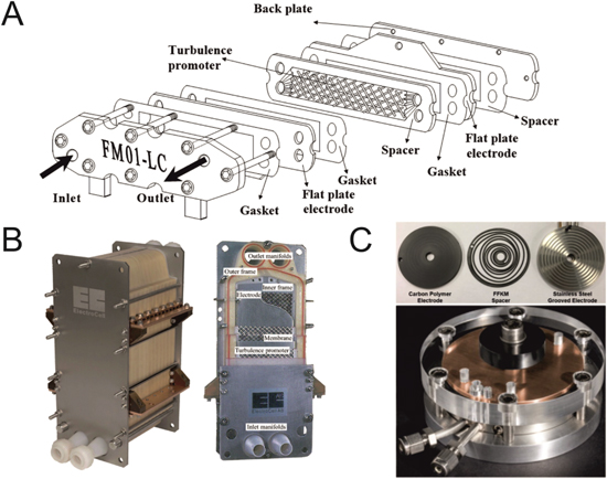
Figure 7. Examples of commercially available electrochemical flow cells. (A) Exploded view schematic for the FM01-LC. Figure taken from Ref. 36, available under Creative Commons (CC-BY) license, published by ACS Publications 2018. (B) The ElectroSyn reactor for pilot and medium operations. The cutaway on the right shows the internal components, including the electrodes plates, turbulence promotors and polymer frames. Images courtesy of ElectroCell A/S, Denmark. (C) Ammonite8 microflow cell. The top image shows the individual components, bottom shows the full assembled cell. A larger model (Ammonite15) is also available for electrochemical synthesis up to the tens of grams scale. Figures taken from Ref. 75, available under Creative Commons (CC-BY) license, published by Elsevier B.V. 2016.
Download figure:
Standard image High-resolution image3D printed flow cells
3D printing technology offers a cost-effective means for rapid prototype development and validation of digital simulations. 76–78 Most components in a traditional flow cell can be fabricated via 3D printing thanks to the increasingly wide range of materials that can be used as a feedstock. Traditionally, polymer materials, including but not limited to poly(lactic acid), poly(propylene) or acrylonitrile butadiene styrene have been used for non-conductive parts such as the flow cell frame or turbulence promotors. 79,80 Users must consider the nature of the electrolyte and products formed, as many polymers are unsuitable due their susceptibility to hydrolysis, particularly under extremes of pH. 81
3D printing technologies are also able to produce conductive structures, allowing customised 3D flow-through electrodes to maximise electrode-solution interaction and generate turbulence in flow-through cell configurations. In most cases, the first stage is to print a 3D scaffold from stainless steel, and then electrodeposit the catalyst to give the same structure at greatly reduced cost. 82 Alternatively, incorporating conductive materials into the polymer feed provides a conductive polymer scaffold for subsequent electrodeposition and use as an electrode. 83 Other groups have incorporated more complex catalysts directly into the polymer, such as Pt/C or MoSe2. 84 These conductive 3D polymer electrodes have been successfully employed in flow cells, 85,86 electrolysers 87 and electrochemical sensors. 88 This presents an opportunity to 3D print an entire flow cell using a low-cost desktop printer, offering an economic route to prototype development.
Porous, 3D electrodes in a flow cell
The choice of porous material depends on the flow profile employed within the cell, primarily whether the electrolyte flows-by or -through the electrode. 60 Flow-by configurations flow electrolyte within a channel over the surface of the porous structure, usually assisted by turbulence promotors to maximise interaction between the electrolyte and the inner porous structure. Flow-through instead fills the channel with the porous structure, requiring the electrolyte to permeate the whole structure during the flow. While maximising the interaction between electrode and electrolyte, the flow-through configuration is practically limited due to pressure drop across the porous electrode material. 89 Flow through configurations therefore are most often employed to very thin electrodes in microfluidic devices. 90,91
3D electrode materials can also be used as scaffolds to support catalytically active particles, which may be deposited through spray coating, 92,93 drop casting 94 or electrodeposition. 55 With flow applications in mind, decorating the conductive scaffold must find a compromise between loading sufficient catalytic material and blocking the porous structure. The tortuosity of the porous material will determine how deep into the pores the catalyst can be loaded. 95 Electrodeposition and drop casting exceed spray coating here, since electrolyte can permeate porous structures whereas spray coating requires a linear line of sight.
An alternate route to high surface area electrochemical catalysts is through fluidised bed reactors. These feature solid catalyst particles held in suspension by an upward gas or liquid flow stream, providing excellent catalyst interaction and mixing for electrochemical reactions. 96 Although fluidised bed reactors suffer from poor electrical contact, they removed the assumption that an electrochemical cell has to have two parallel electrodes. A recent paper demonstrated that improved electrical contact was made using magnetisable electrode particles under the influence of a magnetic field. The strategy resulted in an increase of the electrochemical conversion up to 400% compared to the use of non-magnetised particles. 97
Flow field designs
The challenge in flow field design is to provide optimal flow conditions for reactant supply to and product removal from the electrode surface, while simultaneously minimising the pressure drop between inlet and outlet. To this end, a number of different flow field designs have been employed (Fig. 8). Within these categories, multiple works have investigated varied flow channel widths, depths and orientations, with both experimental and computational approaches probing the flow profile, pressure drop and potential distribution across the electrode surface. 98 Comparison of different flow fields is challenging since varied experimental conditions affect reactor functionality alongside changes in the flow field design. However, some experimental and computational works indicate that serpentine fields outperform the other related designs. 99,100,101

Figure 8. Examples of commonly employed flow field designs for flow-by electrochemical cells. (A) Serpentine, (B) parallel, (C) pin, (D) spiral, (E) interdigitated. Figures adapted from Ref. 99 available under Creative Commons (CC-BY) license, Copyright © 2014 liu, Li, Juarez-Robles, Wang and Hernandez-Guerrer.
Download figure:
Standard image High-resolution imageAn alternative flow field design often employed for 3D porous electrodes is the interdigitated flow field (IFF), which has a series of parallel channels where each channel is blocked at alternate ends. In order to continue the flow, liquid must move through the 3D electrode structure itself. This gives a much greater degree of electrolyte-electrode interaction and a faster rate of reaction. 101 The same technique can also be applied to gas phase flow to encourage interaction with the catalyst at the solid-electrolyte interface. 102 The benefit of IFFs can be thought of as providing flow-through activity, without the associated pressure drop, thanks to the shorter mass transport path length. When designing an IFF, there must be a compromise between the electrode penetration depth and the pressure drop, since greater flow-through characteristics will cause a greater pressure drop. New IFF designs tune channel size and density in order to give a uniform gas/electrolyte distribution for an optimum power density. 103,104 Recent advances have included the development of hierarchical IFFs, where smaller branching channels give an even mass transport distribution whilst providing a small pressure drop. 105
A key challenge with interdigitated flow fields for gas phase electrochemistry is water management. Capillary pressure resulting within porous materials causes water to accumulate in flow channels, hindering gas flow and resulting in unstable cell performance. 106 This challenge lead to the development of new electrodes with hydrophobic and hydrophilic channels within the electrode structure. This has been shown to facilitate water transport within the electrode structure to prevent channel flooding, whilst still favouring gas transport for O2 reduction. 107,108
Rotating disc and cylinder electrode reactors
Rotating disc electrodes (RDEs) are staples in electrochemical laboratories thanks to their well-defined and reproducible electrolyte flow and mass transport profiles, with the transport rate being proportional to the square root of the rotation rate. 109,110 An extension to this design is the rotating ring disc electrode (RRDE), which has a secondary ring electrode on the outside of the central disc. Electroactive species produced at the disc are detected at the ring, allowing in situ quantification of electrochemically generated products. Samples of interest can be drop-cast onto glassy carbon substrates, or affixed to the electrode surface, provided mathematical considerations are made for the sample shape and thickness. 111 This provides an attractive option to assess the impact of flow rate on a reaction in a simplified set up, before moving to a more complex flow cell design.
Rotating cylinder electrodes (RCEs) have received less attention than RDEs. Like the RDE, the rate of mass transport is defined by its rotation rate. The RCE offers a substantially larger surface area along with controlled turbulent flow conditions, making it suitable for up-scaling to industrial applications. 112 Primarily, the large RCE surface area has been employed for electrodeposition applications, including metal recovery and metal powder production. 113,114
Thin film reactors: capillary gap and bipolar trickle tower reactors
Trickle tower reactors use gravity flow to pass the working solution through a porous catalyst material, usually a foam, mesh or bed of particles. 115 The small pore volume gives a thin film of electrolyte over all catalyst surface, giving unique electrochemical conditions. Specifically, the thin electrolyte layer over a large surface area catalyst give a high conversion rate and minimal Ohmic drop when working with weakly concentrated, resistive solutions. 116 This makes trickle towers ideal for water treatment, particularly in the removal of the low concentrations of organic pollutants. 117
The same concept is seen in capillary gap electrodes, where the electrolyte flows down a thin channel between anode and cathode. This can be done on a range of scales from microfluidic devices 118 up to stacks of bipolar capillary electrodes. 119 The small inter-electrode gap provides an additional advantage thanks to the short diffusion paths under laminar flow conditions. This gives rapid rates of reaction without turbulence or forced convection, allowing fast turnover rates than can be supported by relatively simple computation modelling. 120 Microchannel reactors with short inter-electrode distances allow for paired electrochemical processes, where the anodic and cathodic diffusion layers interact to give further reactions between electrochemically generated products. 121
Technological Developments in the Design, Construction and Simulation of Electrodes and Cells
Gas diffusion electrodes (GDEs) for gaseous reactants
Gas diffusion electrodes offer rapid rates of reaction for gas-phase electrochemical processes. The core structure consists of a hydrophobic, gas-permeable structure with a catalyst deposited on the electrolyte-facing side. The keeps mass transport in the gas phase, which is inherently rapid, and circumvents challenges of poor solubility that hinders the rate of reaction when bubbling gas through electrolyte in a beaker or H-cell. GDEs are relatively cheap and simple to manufacture, leading to their extensive use in PEM fuel cells, 122 flow cells 123 and electrolysers. 124 Electrochemically synthesised products may be collected in the gas or liquid phase, or multiple products may be collected from both phases simultaneously, as has been achieved for ethylene and ethanol from CO2 reduction. 125
Many key developments in GDE technologies have focused on the hydrophobicity in order to prevent GDE flooding or dehydration of ion exchange membranes. 126 Commercial GDEs contain hydrophobic components such as PTFE or Teflon to hinder this but further improvements are needed. 127 A number of works have taken steps to improve the hydrophobicity of GDE surfaces, such as hydrophobic oxidised carbon nanotube, 128 PTFE 129 or dimethyl silicon 130 coatings. Other groups have removed hydrophilic components from the GDE entirely. Hydrophobic polymer GDEs or silanized nanoporous alumina membranes can replace traditional carbon materials, 131 with one polymer-based GDE giving efficient CO2 reduction over 150 h. 132
It is equally important to consider the impact of the GDE surface, as the structure and dispersion of catalytic layers will affect the gas dispersion and potential distribution over the GDE. 133 Many GDEs have a microporous layer (MPL) at their surface, usually a combination of carbon black and PTFE, allowing fine control over porosity and hydrophobicity. 134 Multiple works have improved the MPL performance through targeting the porosity or hydrophobicity. Others have removed it entirely, using carbon nanofibers to enhance the electrical conductivity 135 or microporous polymers to tune the hydrophobicity. 136
Microflow channel reactors
The unique combination of laminar flow with short diffusion path length allows for interesting approaches to electrochemical synthesis (Fig. 9). Despite the absence of a membrane, the laminar flow profile gives limited mixing between solutions at the anodic or cathodic side. 137 This has allowed selective interaction of solution species with only one electrode, such as oxidations of alcohols 138 or heterocyclic cross-coupling 139 under mild conditions with only H2 as a by-product produced at the cathode. In these cases, engineering solutions have to allow for H2 release before the solution is recycled or passed onto the next reactor, as H2 bubbles are resistive and will slow the rate of further electrochemical steps. 140

Figure 9. Different approaches to the use of microflow reactors for electrochemical synthesis based on the needs of the reaction mechanism. (A) Direct electrochemical oxidation of benzyl alcohol to the corresponding benzaldehyde at the anode. Cathode balances the charge through hydrogen evolution. Mechanism taken from Ref. 138. (B) Electrochemical conversion of cubane carboxylic acid to alkoxy cubanes. Reaction intermediates are produced at both the anode and cathode, which subsequently react to give the end product. Mechanism taken from Ref. 141. (C) Electrochemical synthesis of metal-salen complexes. A sacrificial anode acts as a source of metal cations for the reaction. Anodic metal dissolution and ligand reduction are performed simultaneously, which combine to give the final complex. Mechanism taken from Ref. 142. (D) Oxidising alcohols to the corresponding ketone via the redox mediator 2,2,6,6-tetramethylpiperidine-1-oxyl (TEMPO). Electrochemistry at the cathode is not considered. Mechanism taken from Ref. 143.
Download figure:
Standard image High-resolution imageBubble generation, usually from H2 or O2 evolution, can generate turbulence within the flow channel to deviate from the laminar regime, which must be considered particularly when operating at large overpotentials. 144 In other cases, bubbles within the flow reactor can be used as part of the synthesis strategy, 145 such as using bubbles as an H2 source for hydrogenation reactions. 146 Bubbles of immiscible liquids can also be used for product extraction within the flow channel, such as for 5-hydroxymethylfurfural synthesis in an aqueous electrolyte, which then moved into organic bubbles to prevent further degradation or polymerisation reactions. 147
Other groups have reduced the inter-electrode gap to facilitate reactions between anodically and cathodically generated species. A method to produce copper-N-heterocyclic carbenes via imidazolium reduction and anodic metal dissolution has been used to produce a wide range of complexes. 142 Reducing the inter-electrode gap also allows the electrolyte content to be reduced by a factor of ten for sulfonamide electrosynthesis vs beaker reactors, 148 with other reactors removing the electrolyte entirely. 149 An alternative approach has been to use the electrochemical step to produce a homogeneous catalyst, which drives the desired substrate reaction, such as using the 2,2,6,6-tetramethylpiperidine-1-oxyl (TEMPO) mediator to drive alcohol oxidations. 143
3D porous electrodes
Metal foam electrodes synthesised from electroless deposition on polymer scaffolds 150 or lost carbonate sintering 151 give random pore orientations. More ordered structures have been produced via selective laser melting, giving access to regular pore distributions 152 and tailored electrode architectures. 153 A number of groups have reduced the pore size in order to increase the active surface area (Fig. 10). Ni electrodeposition inside an anodic aluminium oxide template produced a Ni nanomesh, which was then Pt doped for H2 evolution applications, outperforming commercial Pt/C catalysts. 154 New metal felts have been produces from nanowires, giving a high surface area flow-through electrode with a 4.2-fold increase in conversation rate for 2,2'-bis(bromomethyl)-1,1'-biphenyl intramolecular cyclisation. 155 Hollow Cu fibres have also been used to create a gas diffuser that acts as the working electrode for CO2 reduction in a beaker cell. 156
Other works have focussed on new immobilisation strategies for catalytic material on 3D electrode supports. Catalytic nanoparticles can be immobilised on carbon and metallic foams, felts and meshes through the in situ reduction of the corresponding metal salts, either chemically 157 or electrochemically. 158 The chemical route allows for the physical bonding of catalyst material to a 3D support, such as for gold nanoparticles on graphite felt via thiol moeties 159 or the direct synthesis of hierarchical ZnO nanowires on CuO nanowires on Cu foam via sequential wet chemical and thermal synthesis steps. Electrodeposition has also been used to fabricate mixed-metal catalysts, such as Ag particles on Al 160 and Ni foam, 161 Pt on Ti felt, 162 Fe-doped Pt/C 163 and Mnx Oy -coated graphite felt. 164,165 Simpler approaches can electrodeposit the same material on a conductive scaffold to give a more active surface, such as for electrodeposited high surface area Ni via liquid crystal templating. 166 The electrochemical route is particularly advantageous as the level of doping or surface modification can be simply controlled by varying the applied potential or charge passed.
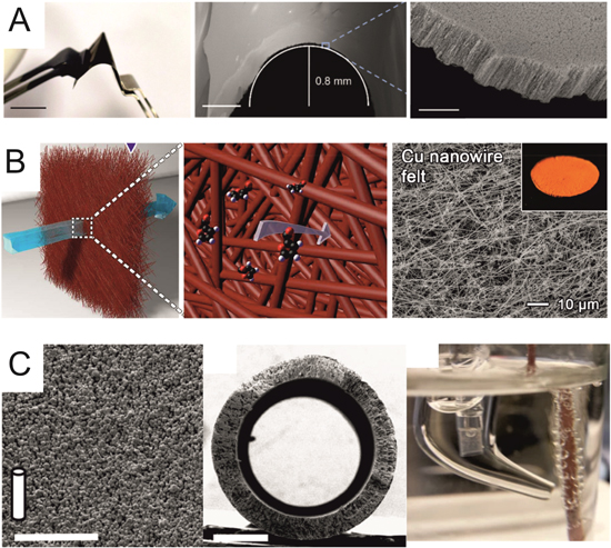
Figure 10. Recent novel 3D electrode designs for varied electrochemical applications. (A) Flexible, self-supported Pt-doped Ni nanowire mesh for hydrogen evolution reaction applications in a liquid H-cell. Scale bars represent 2 cm (left), 500 μm (centre) and 5 μm (right). Figures adapted from Ref. 154, Copyright © 2018, American Chemical Society. (B) High density Cu nanowire felt for single pass electrochemical synthesis in a flow-through liquid phase reactor. Left and centre schematics highlight large substrate conversion rate thanks to dense 3D structure. Figures adapted from Ref. 155, Copyright © 2019, American Chemical Society. (C) Cu porous hollow fibre gas diffusion electrode for electrochemical CO2 reduction. CO is flowed through the central void then passes through the porous walls to react at the liquid interface. Scale bars represent 50 μm (left) and 500 μm (centre). Figures adapted from Ref. 156 available under Creative Commons (CC-BY) license, published by Springer Nature 2016.
Download figure:
Standard image High-resolution imageAlternatively, magnetron sputtering has been used for metallic particle loading on porous GDEs, which gives efficient deposition of small, active particles. 136 Deposition can use a low loading while maintaining activity, which is particularly attractive for costly noble metal materials. 167 As a line of sight method, care must be taken not to block the GDE pores, and particles cannot deposit as deeply within the 3D structure, as in the case of electrodeposition. Similarly, chemical vapour deposition methods have been used to create carbon structures on porous electrode scaffolds, such as for carbon nanofibres 168 on Ni foam or N-doped graphene on Cu foam. 169
3-D printing of electrodes and cell bodies
3D printing developments range from the fabrication of individual components up to total cell fabrication. Materials choices are determined by the solvents and reaction conditions. Many printable polymers are susceptible to degradation, with poly(etherethylketone) (PEEK) recently shown to outperform other materials for chemical, thermal and mechanical stability. 170 Polymer materials are unsuitable for organic media, and can produce hotspots due to poor thermal conductivity, leading to a number of groups to use selective laser melting to 3D print components from stainless steel. 171
The intrinsic precision of 3D printing allows for complex flow fields and multi-channel cell designs to target specific reaction requirements. The impact of flow field pattern (serpentine, parallel, interdigitated, spiral, etc.) on reaction yields has been demonstrated, since it is straightforward to produce flow fields with multiple arrangements and exchange them within the cell. 172 Multiple inlets have also recently been used to introduce reagents stepwise for difluoromethylation or diphenylacetonitrile. 173 Printed cells can be designed to be dismantled for working electrode exchange, 174 or printing can be paused and restarted to confine plate electrodes within the cell structure. 175
3D printing stainless steel or titanium offers a simple route to electrodes with tailored surface area, porosity and flow profile. The desired catalyst can then be added through electrodeposition, as has been achieved for recent Ni 176 and Pt 82 electrodes. An interesting alternative is to incorporate conductive material such as carbon or copper powder into 3D printed polymer to provide conductive polymer electrodes. 88,177 These have been used directly as electrodes, 86 after pre-treatment with solvents 178 or electrochemical cycling 179 or after electroplating to give a metal film on the 3D printed scaffold. 180
Computational modelling of reaction environment in reactors
Broadly speaking, computational models can focus on hydrodynamics, mass transport, heat transfer, current distribution, or combinations two or more of these. The scale and computational cost depends on the number of parameters solved for, the number of assumptions made and the overall complexity of the model geometry. At their simplest, 1D models can be used to calculate to show concentration gradients, flow profiles or potential distributions along flow channels or electrode materials, assuming an even distribution across the second dimension. 181 1D models are built on analytical solutions operating within set boundary conditions. The range of expressions and conditions is extremely broad, being the subject of a number of excellent reviews. 66,182–186 In all cases it is essential to consider the boundary conditions of each model in relation to the experimental conditions in order to ensure a good fit between computational and experimental data. 187
Moving up to 2D allows heterogeneity in catalyst, flow field and other component surfaces to be explicitly modelled. This allows models to incorporate chemical kinetics alongside flow profiles in order to explicitly model reactions inside a flow cell, allowing the user to model the impact of cell potential, feed concentration and flow rate. 188–190 Changes to the reaction environment during operation can also be fed back into the model, such as resistive bubble formation during electrolysis. 191 Modelling via finite-element, -difference or -volume simulation provides clear visual representations of concentrations, flow rates and pressures, allowing reactors designs to be modified to encourage solution mixing and remove stagnant zones. 192
The added computational costs of moving to 3D are often necessary for complex cell designs, particularly when investigating the impact of 3D electrodes, 193,194 parallel stacked cells, 195 flow field geometry 196–198 or turbulence promotors 199,200 on solution mixing and turbulent flow. Modelling the impact of turbulence promoters on flow profile and current distribution allows for a better understanding of how to avoid dead zones and give an even current distribution over a large electrode surface (Fig. 11).

Figure 11. Distribution of chlorine oxidation current efficiency over a planar electrode using a mass transport wall function model. The inlet is at the bottom, with turbulent flow conditions following a turbulence promotor. The more turbulent environment close to the inlet results in a greater current efficiency at the inlet vs the outlet. Increasing the flow rate gives a greater efficiency further along the electrode as turbulence eddies are extended further down the flow channel. Figure taken from Ref. 199 with permission from Elsevier (Copyright © 2018 Elsevier Science S.A. All rights reserved).
Download figure:
Standard image High-resolution imageImmobilised enzyme electrodes and biosynthesis
The natural specificity of enzymes towards a particular reaction offers a promising route to selective electrochemical synthesis. Reactors are primarily based on fuel cell designs, where electrochemical catalysts are replaced with redox active enzymes immobilised onto an electrode surface. 201 Biofuel cells typically employ fuel-specific enzymes at the anode to oxidised the fuel in an aqueous environment, with oxygen reducing enzymes such as multi-copper oxidase or bilirubin oxidase reducing oxygen at the cathode. 202
Since enzymes already offer excellent reaction specificity, much research into enzymatic reactors focuses on facilitating the electron transfer rate between the enzyme and the electrode to improve the power output. Electron transfer rates have been improved via targeted modifications to the enzyme structure 203–205 or through incorporating conductive polymers into the enzyme-electrode assembly. 206,207 Alternatively, electron transfer can be mediated via conductive nanostructures, as has been achieved with nanoparticles, 208,209 graphene, 210,211 and carbon nanotubes. 212–214
Similarly, microbial fuel cells offer environmentally friendly opportunities for reactor designs, particularly with a focus on energy generation and wastewater treatment. 215 These come with a number of important environmental benefits, such as the ability to operate over a wide range of temperatures and pH on diverse types of biomass without the need for energetically expensive aeration. 216 The core design uses microorganisms carry out a redox process at an electrode surface, such as the oxidation of an organic substrate at the anode 217 or nitrification of ammonium to nitrate and subsequent denitrification to nitrogen gas. 218
Present microbial fuel cell designs are held back by restrictive costs; wastewater treatment via microbial cells is currently around 30 times higher than treatment via the conventional activated sludge process due to the need for expensive electrode, separator and membrane materials. 216,219 Advancements in more cost effective materials along with higher power outputs to offset these costs are essential in making this technology viable for upscaling and wider usage. 220 Costs can be reduced by removing separators in favour of a simpler single cell design, but these risk bio-fouling at the cathode over extended periods of operation 221 or electrocatalyst poisoning.
Combinatorial approaches to electrosynthesis
A drawback to electrochemical synthesis is the scale of parameters that must be refined in order to maximise the reaction yield, including but not limited to electrode material, surface structure, electrolyte, solvent, overpotential and temperature. A combinatorial approach allows for the bath analysis of multiple parameters, which greatly accelerates the optimisation process (Fig. 12). 222,223 The first examples used a series of electrodes in a well electrolysis platform to perform galvanostatic electrosynthesis in wells containing different reagents. 224–226

Figure 12. Schematic flow chart for combinatorial electrochemical synthesis via the cation flow system. S and Nu represent possible substrates and nucleophiles respectively. Changing the flow path allows multiple substrate—nucleophile combinations to be systematically produced by the same reactor. Figure adapted from Ref. 227 with permission from Wiley-VCH (Copyright © 2005 Wiley-VCH Verlag GmbH & Co. All rights reserved).
Download figure:
Standard image High-resolution image
Rapid parameterisation has also been achieved with microflow systems, thanks to their precise control over mass transport regime and residence time. 228 Using a flow-switching system allows the same anodically or cathodically generated intermediate to be introduced to multiple reagents in a combinatorial approach. 229 Other reactor designs isolate multiple materials in individual compartments to assess their activity for the same reaction. Reactors designs incorporate individually addressable sensors to assess conversion rate, such as imaging bubble size for water electrolysis 230 or hyphenating to a secondary analysis equipment via switchable flow channels. 231
Electrodeposited composite materials
Many materials, including metals, alloys, ceramics, polymers and composites can be obtained by electrodeposition and/or electrophoretic deposition. While common engineering applications have focussed on e.g., PTFE or SiC in a nickel matrix for tribological use, 10 both anodic and cathodic deposition may be used to synthesise a wide variety of materials, 232 including nanostructured and controlled phase composition materials. 233 Examples include titanates and titanium oxide nanotubes uniformly embedded in a polypyrrole matrix for corrosion protection 234 and MoS2 particles embedded in a nickel matrix for controlled wear resistance and self-lubrication. 235 The importance of controlling the reaction environment around the cathode to tailor the deposit morphology and engineering properties has been highlighted. 236 The choice of electrolyte composition in the field of composite electrodeposition has become more constrained in recent years by environmental concerns over perfluorinated surfactants (used to help disperse hydrophobic materials such as graphene, MoS2 and PTFE) but sol preparation, stability, agitation and enhancement of mass transport to the cathode can be facilitated by preparation of sols using shear blade mixing 237 and ultrasonic agitation. 238 Improved availability of non-ionic liquids 239 and environmentally acceptable water miscible organic acids 240 has extended the choice of electrolytes. Despite decades of development and progress with mechanistic descriptions, 241 a universal model able to describe the rate and composition of composite electrodeposits from a knowledge of process conditions is long awaited.
Conclusions
Electrochemical reactors offer practical solutions to numerous challenges in electrochemical synthesis, from combinatorial approaches to synthesis on a bench-top scale up to industrial production on the tonnage scale. In this review, we have addressed the following key points:
- 1.Electrochemical cells offer a broad range of possible electrode geometries and flow conditions, depending on the needs of the user. Importantly, many electrochemical cells can be developed at the laboratory scale, and then up-scaled for industrial applications with minimal modifications to the core design.
- 2.The use of electrosynthesis cells has extended beyond tonnage scale process chemicals for commodity use to many fine chemicals used in pharmaceutical and medical products.
- 3.A wide range of electrode geometry and electrolyte flow conditions is accessible in published cell designs.
- 4.Parallel plate flow cells are the first choice for flow electrochemical synthesis thanks to their simple assembly and well-defined, reproducible flow profile. Static or magnetically stirred beaker cells will still have a place in the electrochemical laboratory, but they are entirely unsuitable when considering scale-up operations.
- 5.Electrochemically active surface area can be markedly increased via 3D porous electrodes. There are a wealth of different 3D electrode materials readily available, including multiple carbon, textile, metal and metal composite structures. All of these materials can be used as suppled or with additional catalytic coatings, which can be readily tunes to the catalytic needs of a specific electrochemical reaction via physical, chemical or electrochemical deposition. As well as catalytic activity, the mass transport profile of a number of mesh, foam and felt electrodes has been characterised.
- 6.The increasing accessibility of 3D printing facilities has been of great benefit to the field of electrochemical reactor design. Rapid prototyping is possible for reactor components, especially for polymer-based flow fields and turbulence promotors. Recently, this has been extended to the 3D printing of electrodes, either by printing with stainless steel or by incorporating conductive materials into the polymer to print a conductive polymer composite material.
- 7.The composition and architecture of GDE electrodes has been greatly expanded to facilitate a broad range of electrochemical systems, including water and CO2 electrolysers and hydrogen fuel cells. Changes to the hydrophobic structure have been made to prevent GDE flooding in electrolysers and aid in water management for fuel cells.
- 8.Microflow reactor channels, primarily based on the rectangular channel geometry have been introduced for laboratory scale electrosynthesis, particularly in the case of specialty organics. Short anode-cathode distances minimise IR drop even in low or zero electrolyte solvents, and long path lengths give excellent conversion rates.
- 9.Combinatorial electrochemical approaches provide a convenient route to study electrosynthesis of a wide range of reactant/product concentrations. In particular, the deployment of microflow reactors accelerates this process by switching flow channels, allowing an electrochemically generated intermediate to react with multiple substrates.
Future R & D Needs
Moving forward, continued development of electrochemical reactors will depend on advancements in the following areas:
- 1.Characterisation of the distribution of fluid flow, potential, current and reactant/product concentrations for all electrochemical reactors. In particular, quantitative and comparative characterisation of 3D electrodes, specifically focussing on their activity, real surface area and mass transport towards and within their structure.
- 2.More use of established figures of merit to provide a quantitative statement of cell performance and enable comparisons of cell geometry over various operating conditions. This should include studies of batch kinetics under galvanostatic control to examine figures of merit over a wide range of reactant concentration and fractional conversion.
- 3.Longer term evaluation of newly introduced electrode and membrane materials.
- 4.Studies demonstrating scale-up over a wide range of electrode size, cell size, current and production rate of various electrode materials and cell designs for electrosynthesis.
- 5.Accessible, international showcases to demonstrate promising cell components, reactor designs and their performance.
- 6.Increased use and scale-up of microflow channel cells for both inorganic and organic electrosynthesis.
- 7.The sustained tailoring of GDEs beyond precious metal on carbon electrodes intended for use in H2 and O2/air in fuel cells and batteries towards speciality electrosynthesis of materials.
- 8.Uptake of electrochemical synthesis techniques by the broader research community. It is rare to see electrosynthesis techniques and their success being described in sectors outside electrochemistry and electrochemical engineering. It is vital to overcome this by improving education of non-electrochemists, training of industrial personnel and providing adequate process experience to new practitioners.
- 9.The combination of microflow cells with combinatorial techniques presents exciting opportunities to screen electrocatalysts and explore the importance of reaction environment in electrosynthesis.
- 10.The pressure to improve energy efficiency and lower costs provides an incentive to explore regenerative cells which integrate electricity production with electrosynthesis.
- 11.The tailoring of electrode structure needs to be further integrated with the design of selective, nanostructured electrocatalysts to realise next generation multiscale electrode architecture.
- 12.The integration of porous, 3-D electrodes with high photolysis irradiation offers the opportunity to develop high efficiency hybrid tubular cells, incorporating thin film electrolytes, for rapid generation of in situ oxidants for process intensive indirect electrosynthesis.
- 13.More creative use of immobilised enzyme and microbial bioelectrodes opens up a wide range of bioelectrosynthetic routes to speciality chemicals.
- 14.Recent improvements in our ability to model and scale two-phase, solid particle/liquid electrolyte systems provides a new platform for studies in electrosynthesis of chemicals and composite electrodeposits.
- 15.The performance vs construction/cost compromises involved in selecting or progressing a particular reactor design for an electrosynthesis are poorly documented in the literature; case study examples of capital and running costs are rarely seen.