
Abstract
Alloying anodes such as silicon are of great interest for lithium-ion batteries due to their high lithium-ion storage capacities, but have only seen minimal commercial deployment due to their limited calendar life. This has been attributed to an intrinsically unstable solid electrolyte interphase (SEI) that is aggravated by mechanical failure. An amorphous structure can mitigate lithiation strains, and amorphous alloys, or metallic glasses, often exhibit exceptional fracture toughness. Additional elements can be added to metallic glasses to improve passivation. Splat quenching was utilized to prepare an amorphous Al64Si25Mn11 Li-ion anode with a specific capacity >900 mAh g−1 that remains amorphous upon cycling. On this metallic glass electrode, parasitic electrolyte reduction is found to be much reduced in comparison to pure Si or Al, and comparable to that on Cu. The SEI is much thinner, more stable, and richer in fluorinated inorganic phases than the SEI formed on Si, while organic carbonate compounds such as lithium ethylene decarbonate (LiEDC) are notably absent. This study indicates that metallic glasses can become a viable new class of Li-ion anode materials with improved surface passivity.
Export citation and abstract BibTeX RIS

This is an open access article distributed under the terms of the Creative Commons Attribution 4.0 License (CC BY, http://creativecommons.org/licenses/by/4.0/), which permits unrestricted reuse of the work in any medium, provided the original work is properly cited.
Alloying anodes are of great interest as a replacement for graphite in lithium-ion batteries (LIBs) since they can store one or more Li atoms per host atom. Si has garnered the greatest interest in this regard due to its very high theoretical specific capacity (3579 mAh g−1, ∼8300 mAh cm−3) 1 and relatively low market price. However, the durability of commercial batteries with high Si content is limited due to the unstable solid-electrolyte interphase (SEI) on Si 2 and its large volume change upon lithiation and delithiation which leads to cracking and pulverization. 3,4 To date, only relatively small amounts of Si (∼15 wt%) 5 have been incorporated in commercial graphite anodes.
Nanostructured Si electrodes and intermetallic compounds have been extensively explored as methods to overcome the aforementioned challenges with Si. 6–10 However, nanostructured electrodes are difficult and costly to synthesize at large scales, have low packing density which limits volumetric capacity, and exacerbate SEI instability issues due to the increased surface area. 7,11 Among more densely packed electrode materials, it has been found that amorphous materials outperform crystalline materials. 12,13 The absence of grain boundaries has been linked to greater corrosion resistance, 14–16 suggesting improved electrochemical passivity. Better mechanical properties have been attributed to the absence of large strains arising from phase boundaries between distinct lithiated phases that can occur in the lithiation of crystalline materials. In addition, amorphous materials composed solely of metals and/or metalloid elements, termed metallic glasses, have been shown to exhibit exceptional hardness, yield strength, and fracture toughness due to the absence of easy slip systems. 14–16 The case for seeking alternative alloy anodes for LIBs among amorphous materials is quite compelling from a mechanical viewpoint, provided that a comparable energy density, and in particular a stable SEI can be achieved.
This work explores LIB anodes consisting of splat-quenched Si-based metallic glasses. 17–19 These maintain Si, which can alloy with up to 3.75 Li, 13,19 as the main Li-binding element, but distribute it homogeneously within an amorphous matrix. Alloying elements can be selected to maintain the amorphous structure, store more Li, or improve SEI stability. An additional consideration is that new LIB anode materials ought to have a viable large-scale synthesis route. Scalable manufacturing of amorphous alloys requires rapid solidification from the melt. Two common methods are melt spinning 20 and splat quenching, 21–24 which have been used commercially in the production of amorphous Fe-Si-B based magnetic alloys, 25–28 demonstrating that they can produce rapidly solidified material at scale.
To facilitate freezing in the amorphous structure upon cooling, the melt should remain liquid down to as low a temperature as possible, and have a composition that does not crystallize readily. The lowest melt temperatures occur at eutectic alloy compositions, such as the Al-Si eutectic at 577 °C and 12.2 at% Si. 29 In this eutectic, the Al can also lithiate, 30 increasing its specific capacity. The Al-Si eutectic alloy has been successfully employed as an LIB anode, 31 but crystallizes and phase-separates on cooling. Addition of a third metal M impedes phase separation 16 and enables the formation of Al-Si-M metallic glasses. 17,18 Prior studies on sputtered amorphous Al-Si-Mn 19 and Al-Si-Sn 13 thin films have established a region of amorphous compositions with good LIB cycling performance. Based on those studies, the Al64Si25Mn11 composition was selected for this work. The composition was confirmed by energy-dispersive X-ray spectroscopy (EDX). Utilizing splat quenching, which enables cooling rates up to 106 K s−1, 32 we successfully prepared an Al64Si25Mn11 metallic glass (a-AlSiMn) with a capacity exceeding that of graphite and a similar lithiation potential. We demonstrate that, contrary to pure silicon and aluminum, a-AlSiMn forms a thin and stable solid electrolyte interphase that is expected to enable long cycle and calendar life.
Experimental
Metallic glass preparation
Aluminum (Alfa Aesar, 99.99%), Manganese (Alfa Aesar, 99.95%), and Silicon (Sigma Aldrich, 99.95%) were combined into a single parent alloy via arc melting under argon in a Cu cavity, and mechanically broken into small pieces. An Edmund Buehler splat cooling system was used to convert the polycrystalline arc-melted alloy into amorphous alloy foils as follows. A piece of alloy weighing about 10 mg was placed inside the splat-quenching chamber, on a boron nitride sample holder. The chamber was purged three times with Ar and evacuated to a base pressure <10−5 mbar before being filled with Ar (99.999%) to 600 mbar. The alloy was molten and levitated simultaneously using an induction coil. A pyrometer was used to measure the temperature of the melt as 1100 °C. Once molten, the alloy droplet was released from the coil, and fell down to a pair of pistons that "splatted" the droplet, compressing and cooling it rapidly to form an amorphous foil. The high speed of the pistons ensured that the droplet was deformed into a thin layer while still liquid, allowing it to then cool at rates up to 106 K s−1. 32
Electrochemical cell assembly and testing
Metallic glass foils and reference materials were cycled in three-electrode half-cells using Swagelok-type T-cells (Heliume Tech) and a VMP3 potentiostat (Biologic). The cells were assembled with Li foil counter and reference electrodes (Alfa Aesar, 99.9%), glass fiber separators (Whatman, GF-D), and 200 μl of electrolyte (1.2 M LiPF6 in 3:7 w/w ethylene carbonate:ethyl methyl carbonate, Tomiyama). Galvanostatic cycling was performed from open-circuit voltage (OCV) to 0.005 V (vs Li/Li+), then 0.005–1.5 V, at 100 μA cm−2 (20 mA g−1), followed by holds at the cut-off voltages until the current decayed to 20% of its constant-current value. Galvanostatic measurements are normalized to the mass of active material for the determination of specific capacity (mAh g−1).
Cyclic voltammetry (CV) was performed at 0.1 mV s−1 in the same voltage window. For comparison, CV measurements on aluminum, silicon, and copper were also performed. All electrodes are planar with a well-defined surface area to facilitate the study of processes such as SEI formation and parasitic electrolyte reduction that occur at the electrode surface, and to this end CV measurements are normalized to the electrode area (μA cm−2). Aluminum and copper were purchased as foils from Alfa Aesar and used without further preparation. Amorphous silicon electrodes were prepared by sputtering a 50 nm film onto Cu foil as described elsewhere. 33 The as-prepared Si thin films exhibited a 3 nm native SiO2 surface layer, and a density of 2.1 g cm−3. 33 For Si, the lower cut-off was set to 0.05 V to avoid the formation of crystalline Li15Si4. 1
Structural and Chemical Characterization
Powder X-ray diffraction (XRD) was performed on a D2 Phaser diffractometer (Bruker) with a Cu Kα source (1.54 Å). Transmission electron microscopy (TEM) was conducted using an FEI Tecnai TF20 operating at 200 kV. A Discovery DSC 2500 (TA Instruments) was used for differential scanning calorimetry (DSC) measurements. The sample was heated from room temperature to 425 °C with a 10 °C min−1 ramp rate. EDX was performed inside a JEOL 7500F SEM. The composition of a-AlSiMn foils was determined to be Al64Si25Mn11, with a spread of less than 1 at% for each element across five measurements at different locations on the foil.
X-ray photoelectron spectroscopy (XPS) measurements were performed using a Thermo Scientific XPS instrument operated at a base pressure <2 × 10⁻⁸ Torr, using an Al Kα source (1487 eV). Curve fitting was performed using Igor Pro software with a custom program adapted from Schmid et al. 34,35 Data are presented as acquired without any correction for the binding energy scale. Phase assignment was based on the characteristic binding energy separation of the peaks of a given phase within different core-levels. 35–37 Attenuated total reflection Fourier transform infrared (ATR FTIR) spectroscopy was performed using a Shimadzu IR-Tracer 100 instrument inside a nitrogen-filled dry box, equipped with an ATR accessory with a Ge crystal (MIRacle, PIKE Technologies). For both ATR FTIR and XPS, air-free sample transfer was performed using an air-tight vessel, and samples were soaked in dimethyl carbonate for 5 s and dried prior to measurement to remove electrolyte residue.
Results and Discussion
Structure of metallic glass
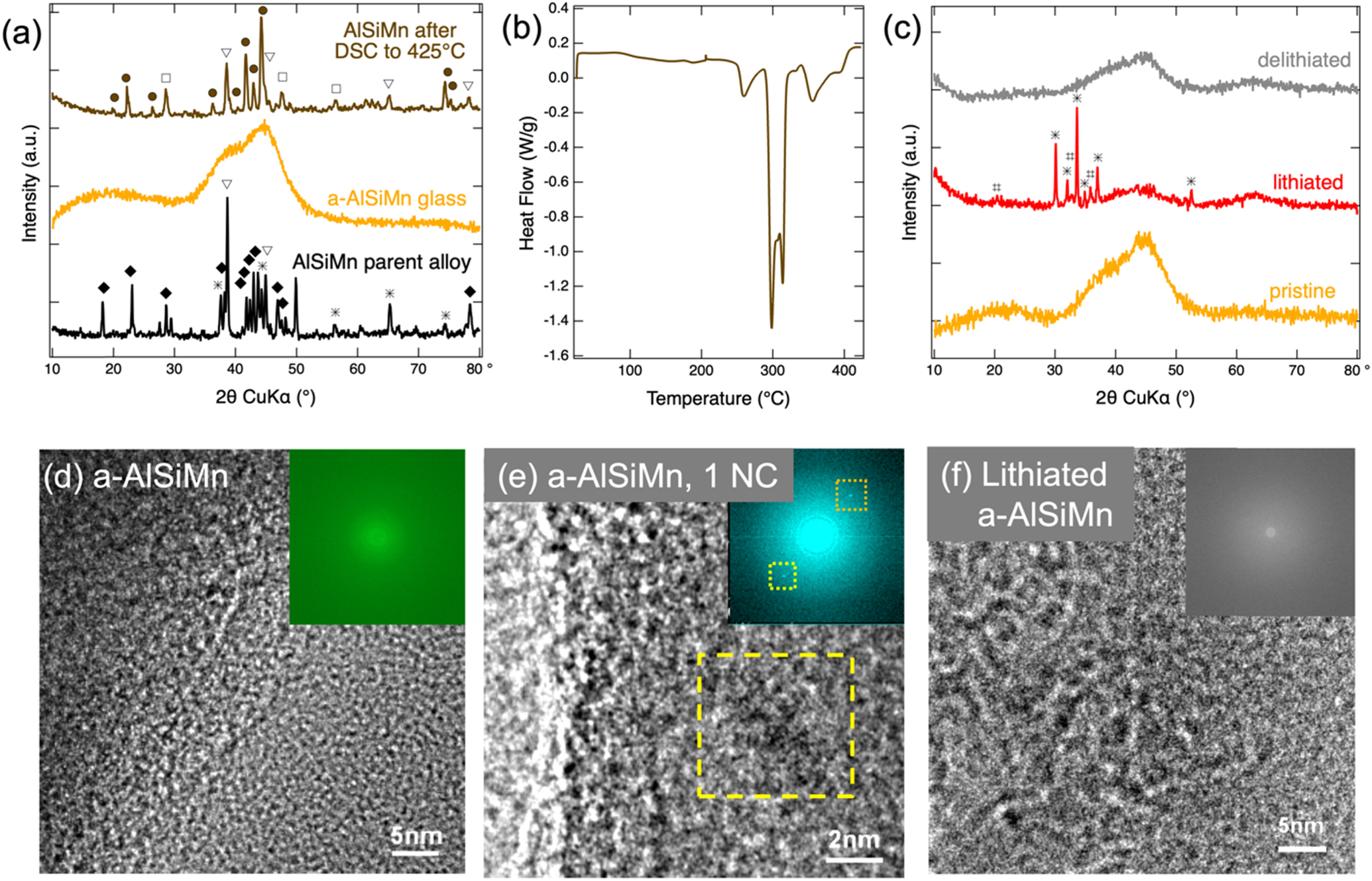
The XRD patterns of the parent alloy and the resulting splat-quenched metallic glass foil are shown in Fig. 1a. The parent alloy consists of a mixture of various crystalline phases. Many of the largest diffraction peaks were indexed to Al, and the intermetallics Al11Mn4 and Mn5Si3. After splat cooling, no sharp crystalline peaks are seen; instead, two broad features at 20° and at 42° are observed. This confirms the formation of a fully amorphous alloy with some short-range order (the peak broadening corresponds to a Scherrer crystallite size of 0.9–1.2 nm 38,39 ).
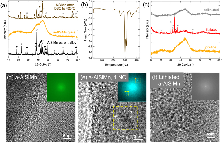
Figure 1. (a) XRD patterns of the Al64Si25Mn11 parent alloy, and splat quenched a-AlSiMn before and after DSC. Patterns are offset from one another for clarity, and peaks are labelled for Si (□, ICSD No. 51688), Al (▽, ICSD No. 182727), Al4.01MnSi0.74 (•, ICSD No. 59362), Al11Mn4 (♦, ICSD No. 10509), and Mn5Si3 (*, ICSD No. 166772). (b) DSC curve of a-AlSiMn. (c) Ex situ XRD patterns of pristine, lithiated, and delithiated a-AlSiMn. Lithiation was achieved by a 0.1 mV s−1 voltage sweep to 0.005 V followed by a 5 h hold. The delithiated sample underwent a full CV cycle at 0.1 mV s−1. Patterns are offset from one another for clarity. Reflections marked for the lithiated sample are LiOH•H2O (ICSD No. 9138, *) and LiOH (ICSD No. 27543, #), which are an artefact arising from reactions of inserted Li with ambient oxygen or moisture during the ex situ XRD measurement. High-resolution TEM images of pristine a-AlSiMn (d) showing its amorphous structure, an isolated ∼4 nm nanocrystal within pristine a-AlSiMn (e) (highlighted by a yellow box), and lithiated a-AlSiMn (f). The insets in (d)–(f) shows the corresponding SAED patterns.
Download figure:
Standard image High-resolution imageThe DSC curve (Fig. 1b) of the material shows clear exothermic peaks above 250 °C and XRD performed before and after DSC (Fig. 1a) indicates that these exothermic processes correspond to crystallization of the material, releasing about 150 J g−1. All peaks of the crystallized material were successfully indexed to Al, Si, and Al4.01MnSi0.74. This demonstrates that to obtain the amorphous alloy it was critical to achieve rapid cooling rates in order to lower the temperature of the melt to <250 °C before any crystalline grain growth could occur. The transition temperature is nevertheless sufficiently high that no phase transitions are expected due to heating during normal battery operation.
Further evidence for the predominantly amorphous nature of the a-AlSiMn is provided by TEM images and the corresponding selected area electron diffraction (SAED) patterns (Figs. 1d, 1e). Across tens of TEM images collected from various sample locations only very few nanocrystals (<5 nm) were found (yellow square in Fig. 1e).
Charge-discharge behavior
In order to demonstrate that this new material can store enough Li to make it a viable alternative to graphite, galvanostatic cycling was performed; the first two cycles are shown in Fig. 2. During these two cycles, the a-AlSiMn was charged to 1510 and 1630 mAh g−1, respectively. The theoretical capacity of the a-Al64Si25Mn11 is 1400 mAh g−1, assuming that, as in the elemental anodes, one Li per Al, and 3.75 Li per Si can be stored (Si then provides 60% of the capacity, and Al the remaining 40%). The theoretical and experimental values are in reasonable agreement, given that some charge is consumed in SEI formation, that insertion of slightly more than 1 Li per Al has been reported, 30 and that the capacity of the glass alloy could deviate from the specific capacities of the constituent elements.

Figure 2. First two galvanostatic cycles of a-AlSiMn cycled between 0.005 and 1.5 V. The sample was cycled at 100 μA cm−2 (20 mA g−1), and held at the cut-off voltages until the current decayed to 20% of the constant current value.
Download figure:
Standard image High-resolution imageThe reversibility of galvanostatic lithiation is somewhat limited in the a-AlSiMn foils. The Coulombic efficiency is 53% and 56% for the first two cycles, and increases upon cycling, in Fig. 2 and in the cyclic voltammetry measurements shown in Fig. 3. It is worth noting that these foils are >2 μm thick and have not been optimized for long-term cycling; they are designed to facilitate interfacial stability and SEI composition measurements. It has been shown that the Coulombic efficiency of an alloy anode can be improved by reducing the particle size or film thickness of the active material, 40 and by preparing a composite electrode with conductive additive and binder, 41 and we therefore expect that higher Coulombic efficiencies can be achieved in composite electrodes with a-AlSiMn powders. Nevertheless, the a-AlSiMn foil allows the extraction of 794 mAh g−1 in the first and 914 mAh g−1 in the second cycle, demonstrating that it can in principle reversibly store capacities multiple times greater than graphite.
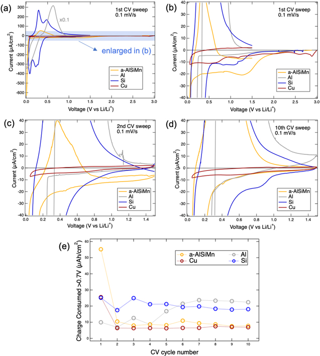
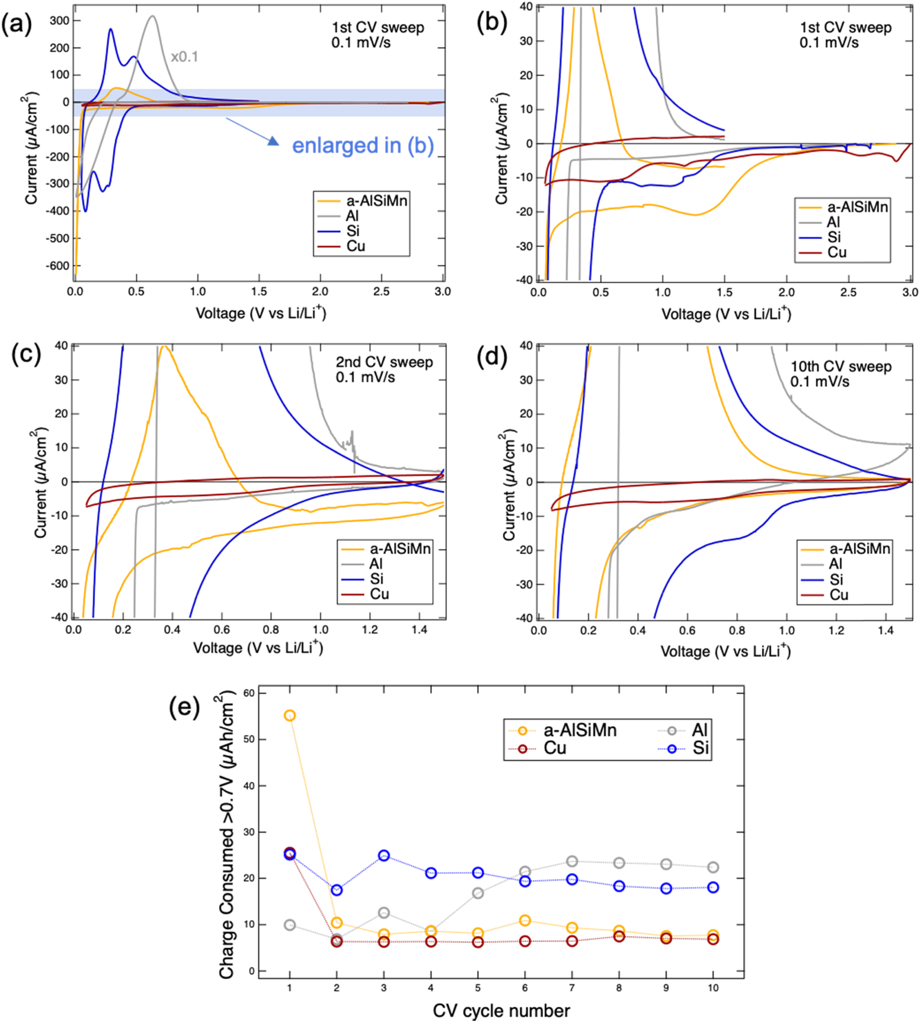
Figure 3. Cyclic voltammograms of a-AlSiMn (yellow) as compared to 50 nm amorphous Si (blue), Cu foil (brown), and Al foil (grey). (a) First cycle, Al current rescaled (×0.1). The low-current regions, which reveal electrolyte reduction processes, are enlarged in (b), (c), (d) for the 1st, 2nd and 10th cycles, respectively (Al current not rescaled). Panels (b)–(d) have the same current axes but different voltage axes. The charge consumed above 0.7 V during cathodic sweeps was calculated for all samples and cycles and is plotted in (e). The current at the beginning of the cathodic sweep (1.5 V for all but the first cycle) was taken as a baseline and subtracted.
Download figure:
Standard image High-resolution imageIn order to investigate the structural changes that a-AlSiMn undergoes during cycling, XRD patterns were acquired on pristine, lithiated, and delithiated a-AlSiMn and are shown in Fig. 1c. Upon lithiation, the broad XRD bands of pristine a-AlSiMn at ∼20° and ∼42° are reduced, and a new broad band appears at ∼62°. Upon delithiation, the band at 62° decreases in intensity, and the pristine a-AlSiMn bands at 20° and 42° re-emerge. The band at 62° is attributed to lithiated a-AlSiMn, and the incomplete reversibility of the XRD mirrors the partial irreversibility of charge extraction from the a-AlSiMn foil (Fig. 2). The sharp peaks visible for the lithiated a-AlSiMn can be indexed to the hydrated and unhydrated forms of LiOH, and are an artefact arising from exposure of the sample to ambient air before and during XRD. 42 No crystalline phases containing Al, Mn, or Si were observed, demonstrating that a-AlSiMn remains amorphous during lithiation and delithiation. The peak broadening corresponds to Scherrer grain sizes below 1.2 nm for all peaks, indicating that there is merely short-range order. This observation is further corroborated by TEM analysis conducted on the lithiated a-AlSiMn (Fig. 1f). The high-resolution TEM image and the SAED pattern of the lithiated anode show no sign of a crystalline phase. XRD and TEM indicate that the material is likely to maintain any beneficial mechanical properties conferred by an amorphous structure throughout cycling.
Electrochemistry and surface passivity
Cyclic voltammetry measurements of a-AlSiMn (Fig. 3) show that lithiation of the a-AlSiMn occurs at 0.05 V during the first cycle, and at 0.25 V during subsequent cycles. An initially more negative lithiation potential has been observed for both Si 36,43 and Al 30 anodes, and has been attributed to the need to lithiate surface oxides during the first cycle, and the need to break up a tough bulk structure (crystalline Si, crystalline Al respectively) during the first cycle. Since metallic glasses are known to be materials with high yield strength and fracture toughness, 14–16 and as it will be shown later that a-AlSiMn also exhibits a surface oxide, either effect could be responsible for the lower first cycle lithiation potential.
From the second cycle onwards, lithium insertion is observed below 0.25 V. This is consistent with typical Li alloying potentials of Si (LixSi, 0.18 V and 0.06 V 44 ), but is significantly lower than the Li alloying potential for Al (LiAl, ∼0.39 V 30 ). This indicates that the amorphous alloy structure of a-AlSiMn decreases the potential at which Li is alloyed with Al. Li extraction occurred mostly between 0.2 and 0.6 V, consistent with reported values for Al and Si (LiAl: 0.43 V; 40 LixSi: 0.3, 0.5 V 44 ). The metallic glass is therefore expected to enable LIBs with similar voltages as Al and Si. Combined with its specific capacity, the Li insertion/de-insertion voltages show that an a-AlSiMn anode has an energy density that is of interest for improved LIBs, provided it exhibits good SEI stability.
To assess SEI stability, the currents that flow above the lithiation potentials are a useful indicator as they arise from the irreversible consumption of charge due to electrolyte reduction and SEI formation. These are shown in Figs. 3b–3d. During the first CV cycle (Fig. 3b), these currents are low for Al, and of comparable magnitude for amorphous Si and Cu, whereas they are higher for a-AlSiMn. An electrolyte reduction peak is observed at about 1.3 V for a-AlSiMn, with smaller peaks visible at 1.1 V for Si, and 0.7 V for Cu. Studies on glassy carbon 45 and silicon electrodes 37,43 conducted with the same electrolyte have shown that the LiPF6 salt is reduced at more positive voltages than the organic solvent molecules, so these peaks are tentatively attributed to LiPF6 reduction. The formation of LiF, P-O and F-P-O species observed on a-AlSiMn after CV (Fig. 4) is in agreement with this assignment. No clear oxidation peaks are observed above the lithiation potentials. It can be seen that during the first CV cycle SEI formation consumes more charge on a-AlSiMn than on Al, Si, or Cu.
During the second CV cycle (Fig. 3c), electrolyte reduction currents are reduced on all electrodes and no pronounced reduction or oxidation peaks are observed. This suggests some degree of SEI formation and passivation on all electrodes. By the tenth CV cycle (Fig. 3d), some interesting differences arise. While the Cu voltammogram is essentially the same during the second and tenth cycle, as one might expect as Cu is commonly used as an LIB anode current collector due to its interfacial stability in organic carbonate electrolytes, the electrolyte reduction currents on a-AlSiMn are lower, and now match those on Cu. This suggests that a-AlSiMn achieves a similar level of surface passivation under these conditions. Meanwhile, the electrolyte reduction currents on amorphous Si have markedly increased, and a reduction peak has appeared at 0.85 V. The electrolyte reduction currents on Al have also increased.
For quantification of the charge consumed by electrolyte reduction, the cathodic charge consumed above 0.7 V is integrated from the voltammograms and is shown in Fig. 3e. The value of 0.7 V is selected as a cut-off because Fig. 3 indicates that no lithiation occurs above 0.7 V in any of the samples. The current at the beginning of the cathodic sweep (1.5 V for all but the first cycle) is subtracted as a baseline prior to integration. The charge consumed by a-AlSiMn is highest in the first cycle, but quickly decreases to the levels seen on Cu. Conversely, the charge consumed by the Si electrode remains 2–3× higher, and the charge consumed by Al actually increases to the same levels as Si, indicating an unstable SEI. The a-AlSiMn metallic glass alloy is seen to promote formation of a stable SEI during cycling.
SEI Composition
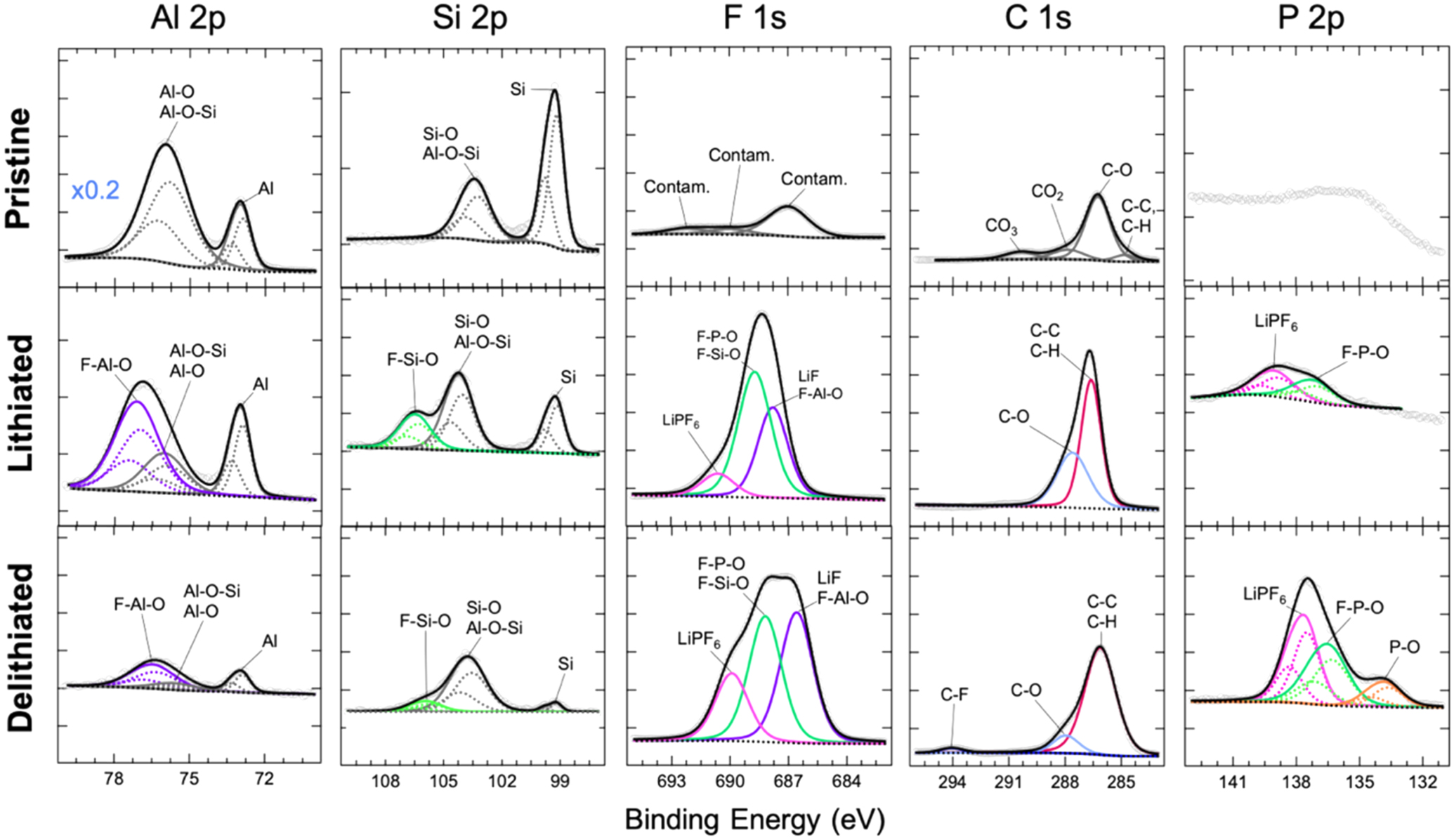
To elucidate the composition of the SEI formed on the a-AlSiMn anode that enables this degree of surface passivity, XPS was performed on pristine a-AlSiMn, and a-AlSiMn after half a CV cycle (lithiated) and a full CV cycle (delithiated); results are shown in Fig. 4. Quantitative XPS analysis reveals that the surface composition of pristine a-AlSiMn is Al84Si15Mn1 (Mn 2p3/2 core-level not shown), as compared to the bulk composition of Al64Si25Mn11 measured by EDX. The surface consists mainly of Al and Si, both of which are oxyphilic and show a degree of oxidation (the pristine samples were stored in air). In particular, an aluminosilicate phase is identified (labeled Al-O-Si in Fig. 4). The reason for the absence of Mn at the surface requires further study, but might arise from a preferential oxidation of Al and Si in air, burying Mn deeper in the sample.
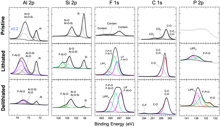
Figure 4. Fitted core-level XPS data for Al, Si, F, C and P measured on a-AlSiMn in the pristine state, after half a CV cycle (lithiated) and after a full CV cycle (delithiated). Each column shares vertical and horizontal axes, except the pristine Al 2p panel which was rescaled as indicated. The vertical axes differ across columns. Raw data is shown as grey points, fits are shown as lines. The Al 2p, Si 2p and P 2p core levels are fitted using tabulated values for the spin–orbit splitting, and component peaks are plotted as dashed lines. 46 The new phases formed at the surface upon cycling are highlighted in color, and each phase has the same color across all core levels.
Download figure:
Standard image High-resolution imageUpon lithiation, aluminum and silicon oxides become fluorinated. The SEI must be extremely thin for Al and Si core levels to remain observable, given the probing depth of ∼5 nm. Prior studies on both Si 43 and Al 30 have shown that surface oxides can act as part of the SEI due to their high electronic resistivity, reducing the amount of SEI growth that occurs due to electrolyte decomposition. Lithiated AlOx in particular has been reported to exhibit Li+ conductivities up to 10−6 Scm−1, and high critical interfacial shear stress, allowing it to act as a durable SEI. 30
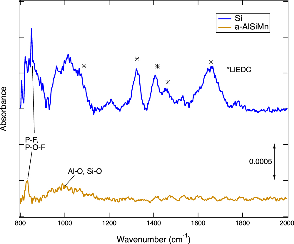
The thin SEI on a-AlSiMn is mostly comprised of fluorinated species such as LiF, and F-P-O groups. Some LiPF6 residue is also observed. Upon delithiation the SEI grows a little thicker but shows only marginal variation in composition. The fluorinated compounds that were present after lithiation are also present after delithiation, indicating a stable SEI. A small amount of phosphate species is observed, and a trace amount of fluorinated organic species. Both the lithiated and delithiated samples also exhibit some C–C/C–H and C–O bonds, but no attribution could be made on the sole basis of the C1s core levels. Conspicuously, no carbonate (CO3) signal was observed. ATR FTIR spectroscopy was performed to characterize the organic species present on the surface (Fig. 5). While a peak attributable to Al-O and Si-O bonds was observed, 47,48 in agreement with XPS, the surface concentration of organic species 49–51 on a-AlSiMn proved to be too low to be detected.
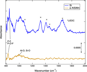
Figure 5. ATR FTIR measurement of delithiated a-AlSiMn and Si samples (after one CV cycle). While Si shows a number of peaks attributed to lithium ethylene dicarbonate (LiEDC, *), 33 no peaks corresponding to the organic groups typically observed in FTIR spectra of SEI layers 49–51 are observed for a-AlSiMn. A peak observed at ∼1000 cm−1 is attributed to a combination of Al-O-Al, Si-O-Si, and Al-O-Si groups. 47,48 Both samples exhibit a P-F, P-O-F peak. 33
Download figure:
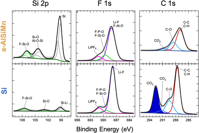
Standard image High-resolution imageThe thin and largely inorganic SEI formed on a-AlSiMn differs substantially from the thicker and more organic SEI typically formed on Si electrodes in comparable electrolytes. 33,37 A comparison of XPS data collected on an a-AlSiMn foil and a50 nm amorphous Si thin film that were galvanostatically lithiated in the same electrolyte is given in Fig. 6. The XPS spectra show a much lower Si 2p signal for Si than a-AlSiMn, confirming that a thicker SEI is formed on Si. Both electrodes have SEIs containing LiF, F–P–O groups, hydrocarbons, and C–O groups, but no carbonate (CO3) peak is observed in the C1s level of the a-AlSiMn, whereas the Si electrode exhibits a strong CO3 signal. It has been reported that on Si anodes, carbonate species resulting from the decomposition of the electrolyte solvents EC and EMC produce a thick, organic-rich SEI during the first lithiation step. 36,37,43 This is confirmed by ATR FTIR (Fig. 5), which shows multiple peaks corresponding to lithium ethylene decarbonate (LiEDC) for the Si electrode; these are absent on a-AlSiMn.
Figure 6. Fitted core-level XPS data for Si, F, and C measured on lithiated a-AlSiMn and Si (after half a galvanostatic cycle). Each column shares vertical and horizontal axes; vertical axes differ across columns. Raw data is shown as grey points, fits are shown as lines. The Si 2p core levels are fitted using tabulated values for the spin–orbit splitting, and component peaks are plotted as dashed lines. 46 The key difference between the two electrodes is the CO3 signal observed on Si (shaded).
Download figure:
Standard image High-resolution image
It has been proposed that LiEDC is responsible 33 for the "breathing" effect often observed in Si anodes, 43,52,53 when the SEI thickens with each lithiation and becomes thinner with each delithiation, leading to an inherent SEI instability. The absence of unstable LiEDC on a-AlSiMn may arise either from a lack of EC or EMC reduction on a-AlSiMn electrodes—perhaps because a surface oxide together with LiPF6 decomposition products, which form earlier, has already passivated the electrode 43,45 —or from the formation of EC or EMC reduction products that do not attach to the a-AlSiMn electrode and thus do not become part of the SEI. Either explanation would be consistent with the primarily inorganic SEI observed here.
Overall, the data shows that the SEI formed on a-AlSiMn is much thinner than the SEI observed on Si; it is richer in inorganic species and does not contain carbonate decomposition products. This correlates with lower parasitic charge consumption after a few cycles (Fig. 3), enabling a more stable SEI as compared to the reference alloy anodes Si and Al.
Conclusions
An amorphous Al64Si25Mn11 metallic glass (a-AlSiMn) foil Li-ion anode was successfully produced via splat quenching. It exhibits a specific capacity exceeding 900 mAh g−1 and a low lithiation potential, making it suitable for high-energy density LIBs. XRD indicates that the material remains amorphous throughout cycling, which is expected to prevent mechanical failure on cycling. Most importantly, and in contrast to Si and most intermetallic anodes, a stable SEI was observed in an organic carbonate-based electrolyte, with lower parasitic electrolyte decomposition currents than those observed on pure Al or Si model anodes. The SEI is very thin, and rich in fluorinated species such as LiF, F–P–O groups, and fluorinated oxides of silicon and aluminum, whereas very few organic species are present, suggesting that the reduction of solvent molecules is greatly inhibited. Most notably, no LiEDC is formed on a-AlSiMn, resulting in a thinner and more stable SEI than on Si. This study demonstrates that metallic glasses could resolve the interfacial instability that has traditionally plagued alloying anodes such as Si, enabling LIBs with greatly improved energy density, cycle and calendar life. Splat quenching could be deployed as a scalable, high-yield and inexpensive method of manufacturing a new class of intermetallic glass anode materials for commercial Li-ion battery applications.
Acknowledgments
The authors thank Rohit Satish for help with XRD analysis. This work was supported by the Assistant Secretary for Energy Efficiency and Renewable Energy, Office of Vehicle Technologies of the U.S. Department of Energy under the Silicon Electrolyte Interface Stabilization (SEISta) Consortium directed by Brian Cunningham and managed by Anthony Burrell, with work at the Molecular Foundry supported by the Office of Science, Office of Basic Energy Sciences, of the U.S. Department of Energy; both under under Contract no. DE-AC02-05CH11231. Si thin film preparation was performed by UT-Battelle, LLC, under Contract DE-AC05-00OR22725 with the U.S. Department of Energy.