
Abstract
Sulfide solid-state electrolyte (SE) possesses high room-temperature ionic conductivity. However, fabrication of the free-standing, sheet-type thin sulfide SE film electrolyte to enable all-solid-state batteries to deliver high energy and power density remains challenging. Herein we show that argyrodite sulfide (Li6PS5Cl) SE can be slurry cast to form free-standing films with low (≤5 wt%) loadings of poly(isobutylene) (PIB) binder. Two factors contribute to a lower areal specific resistance (ASR) of the thin film SEs benchmarked to the pristine powder pellet SSE counterparts: i) 1–2 orders reduced thickness and ii) reasonably comparable ionic conductivity at room temperature after the isostatic pressing process. Nevertheless, an increasing polymer binder loading inevitably introduced voids in the thin film SEs, compromising anode/electrolyte interfacial ion transport. Our findings highlight that electrolyte/electrode interfacial stability, as well as the selection of slurry components, including sulfide SE, binder, and solvent, play essential roles in thin film sulfide electrolyte development.
Export citation and abstract BibTeX RIS

This is an open access article distributed under the terms of the Creative Commons Attribution 4.0 License (CC BY, http://creativecommons.org/licenses/by/4.0/), which permits unrestricted reuse of the work in any medium, provided the original work is properly cited.
Advances in solid electrolytes (SEs) with superionic conductivity and stabilized electrode-electrolyte interfaces are key enablers for all-solid-state batteries (SSBs) to meet the energy density and cost targets for next-generation batteries for electric vehicles. Sulfur is an inexpensive, Earth-abundant element, making sulfides an attractive option for next-generation SEs. In comparison to oxide SEs, sulfide SEs offer better ionic conductivity and processability. 1 Among the sulfide SEs, lithium argyrodites (Li6PS5X, X=Cl, Br, or I) are particularly attractive due to their high room temperature ionic conductivity (comparable to liquid electrolyte), scalability through solution-mediated synthesis, and ease of processing. 2,3
To meet the energy storage requirements demanded by the blossoming electric vehicle market, the development of processing techniques amenable to existing industrial processes is paramount. Sheet-type, free-standing SE films are, therefore, of great interest since they are based on scalable slurry processing and can be readily integrated into the current roll-to-roll infrastructure in Li-ion battery manufacturing lines. 4,5 Most lab-based research efforts focus on pelletizing sulfide SEs. Pressing pellets is disadvantageous for two primary reasons: 1. the pressures required to form a pellet approach prohibitive levels when scaled up from laboratory size (∼1'' in diameter); and 2. due to their poor mechanical properties, pellets have a finite lower bound on their thickness which limits their cell-based energy densities. 4,6,7 By incorporating a polymer binder, thinner and more mechanically robust films can be fabricated using ubiquitous slurry casting methods. 5,8
Sulfide SEs are prone to nucleophilic attack in the presence of polar solvents. 4,5,8,9 Thus, the choice of binder is limited to non- or low-polar polymers. A close polarity match between the polymer and SE leads to stronger binder-particle adhesion. 8 Inada et al. found that ionic transport is greatly hindered by binder-coated particles, which results from too great an affinity between the binder and SE particles. 10 Ito et al. found using the same binder in the SE separator and the composite cathode led to the dissolution of the layers at their interface, highlighting the importance of fabricating free-standing films instead of directly coating the separator layer onto the electrode. 11,12
A considerable amount of work has been performed to fabricate thin, free-standing SE separators. Riphaus et al. compared mechanical and electrochemical properties of slurry-processed Li10SnP2S12 (LSPS) free-standing sheets fabricated using between 2.5 and 10 wt% poly(isobutylene) (PIB), poly(ethylene vinyl acetate) (PEVA), hydrogenated nitrile butadiene rubber (HNBR), or styrene-butadiene rubber (SBR). They found HNBR and PIB only required a minimum of 2.5 wt% to form a free-standing film, while PEVA required 7.5 wt%, and SBR required 10 wt%. 12 Emley et al. investigated the effect of solids loading in Li6PS5Cl (LPSCl) thin film fabrication using 5 wt% nitrile butadiene rubber (NBR). 13 In a study performed by Zhu et al., 1 wt% silicone rubber (SR), an electrospun cellulose supporting substrate, and 500 MPa were utilized to fabricate 60 μm-thick free-standing films with impressively high ionic conductivity (up to 6.3 mS cm−1). 14 Many studies have developed methods of producing thin films, but none have addressed the effects of surface micro-defects brought about by phase segregation of trace non-polar binder on electrochemical performance. Thus, there exists a gap in understanding the adverse effects of small loadings of non-polar binder in LPSCl composites on the electrochemical and morphological properties of these separators. PIB was chosen as the model binder in this work due to its distinctive mechanical, chemical, and electronic properties. These include its rubbery nature at room temperature and its extremely low electronic conductivity, which are beneficial for the mechanical and electrochemical properties of solid-state separators. 15,16 In addition, over the last 70 years, PIB has become ubiquitous in a number of industrial and commercial applications because of its low cost, which demonstrates PIB's scalable application. 16 On account of its low polarity, toluene was selected as the solvent. 17 In our study, we explored the effects of PIB content at 1, 2, and 5 wt% on the electrochemical performance of PIB-Li6PS5Cl composite separators. Furthermore, we correlated the measured electrochemical properties to structures observed via microscopic and spectroscopic techniques. Finally, the mechanical robustness of the free-standing separators was observed.
Free-standing films were fabricated with 2 wt% binder to attain consistent film quality. Processed films were characterized using Raman spectroscopy, scanning electron microscopy (SEM), electrochemical impedance spectroscopy (EIS), and Li stripping and plating tests. Results were benchmarked against as-received LPSCl and toluene-treated LPSCl (0 wt% PIB-LPSCl). Our findings highlight the importance of the selection of slurry components, including sulfide SE, binder, and solvent, as it relates to the development of high-performance electrolyte composite materials capable of achieving ideal form factors.
Experimental
Materials
PIB (850 kg mol−1; Scientific Polymer Products, Inc., New York, U.S.) was dried at 100 °C under vacuum overnight and dissolved in anhydrous toluene (dried using 4 Å molecular sieves for a minimum of two weeks). Li6PS5Cl (3–5 μm; NEI Corp., New Jersey, U.S.) was used as received.
Thin film preparation
PIB was dissolved in toluene (7.4 wt% PIB), and subsequently, LPSCl was added to make 0, 1, 2, or 5 wt% PIB content mixtures with a SE mass ratio (dry SE:polymer solution) of 0.6. The slurries were mixed via ball milling with 5 mm ZrO2 balls for a minimum of 18 h and subsequently tape cast in an argon atmosphere onto a silicone-coated mylar substrate (The Tape Casting Warehouse) using a drawdown bar set to an 0.008-inch gap. After drying for 20 min, the top sides of the films were covered with an identical silicone-coated mylar substrate, and the entire sandwich assembly was sealed in a pouch for calendering (MTI cold roller press, MSK-HRP-MR100DC) at room temperature. The films were then removed from the pouch in an Ar-filled glovebox and dried under vacuum for two days. An illustrated process schematic is shown in Fig. 1.
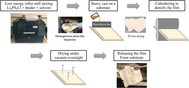
Figure 1. Process schematic depicting PIB-LPSCl composite film fabrication.
Download figure:
Standard image High-resolution imageCell fabrication
All pressure-dependent ionic conductivity and Li stripping/plating data were collected using poly(ether ether ketone) (PEEK) cells. PEEK cell assemblies were fabricated in-house and consisted of a ½'' PEEK mold fixed to a steel baseplate, a stainless-steel spacer, electrodes on either side of the sample, another stainless-steel spacer, and a stainless-steel plunger. 18
All temperature-dependent ionic conductivity measurements were performed in CR2032-type coin cells. Samples were weighed and cold pressed with carbon-coated aluminum (C@Al) current collectors in a ½'' stainless steel split die at 600 MPa for 5 min. Formed C@Al|LPSCl|C@Al symmetric cells were ejected from the die and hermetically sealed in a coin cell with a spring and 500 μm-thick stainless-steel spacer. The symmetric cells tested in this study were cold-pressed to form good contact with the electrode surface. A pair of Nyquist plots demonstrate the effects of the pressing step on the interfacial resistance in Fig. S1.
Electrochemical measurements
Toluene-treated LPSCl or PIB-LPSCl composite samples were prepared as described above for temperature-dependent conductivity measurements. The cells were secured in coin cell holders and placed in a programmable climate control chamber. Potentiostatic electrochemical impedance spectroscopy (PEIS) was conducted at temperatures between 80 and 20 °C in 10 °C increments for 4 cycles using a VMP3 potentiostat (Biologic). Samples were held at each temperature for 80 min to ensure thermal equilibrium before each measurement. Measurements were performed between 1 MHz and 100 mHz with an excitation amplitude of 10 mV. The ionic conductivity, σ, was calculated using the following Eq. 1, where R is the resistance at the high-frequency intercept of the Nyquist plot, A is the cross-sectional area of the cell, and L is the separator thickness.

Pressure-dependent ionic conductivity measurements were taken in PEEK cells at room temperature. Approximately 50 mg toluene-treated LPSCl (denoted as 0 wt% hereafter) or PIB-LPSCl was measured out into a PEEK cell with two ½'' C@Al current collectors. 0, 1, 2, and 5 wt% PIB-LPSCl were pressed at 20 MPa for 5 min. At the end of 5 min, conductivity was recorded, and the pressure was released. After an additional 5 min, 10 MPa stack pressure was applied, and conductivity was again recorded. This process was repeated with a stack pressure of 5 MPa. Finally, the conductivity was recorded at approximately 0.5 MPa. The approximate time between measurements was 10 min. Final pellet thicknesses ranged from 323 to 364 μm post-fabrication.
Li stripping and plating tests were performed in PEEK cells at room temperature. Cells were cold pressed at 600 MPa for 5 min with Li-coated copper electrodes (Li@Cu; 40 μm Li layer; MSE) and cycled with a stack pressure of ∼1 MPa. Cells were cycled at ± 40 μA/cm2 for 100 charge/discharge cycles, with 1 hour for striping followed by 1-hour plating. To assess critical current density, the Li|LPSCl|Li symmetric cells were respectively cycled for 6 charge/discharge cycles at 80 μA cm−2, 118 μA cm−2, and 236 μA cm−2.
Characterizations
The morphologies of the SE samples were evaluated using scanning electron microscopy (SEM) (Zeiss MERLIN Field Emission SEM) equipped with an In-lens detector. An accelerating voltage of 1 kV was used.
ImageJ and MATLAB's Image Processing Toolbox were used to process micrographs. Collected tiff files were first cropped and converted to grayscale images. Using a reference image and MATLAB's imhisteq function, grayscale images underwent histogram matching to equalize brightness and contrast. Images were then converted back to tiff files for further processing. In ImageJ, the image type was converted to 8-bit, and pixel value thresholding was performed to isolate visible pores or dips on the sample surface as white spots on a black background. Apparent surface porosity values were taken as the percentage of white pixels. For each sample, results from four images at different magnifications were processed: 500×, 1 k×, 5 k×, and 10 k×.
All Raman maps were collected on a confocal Raman spectrometer (WITec, GmbH 532 nm, objective = 20×, a grating with 600 grooves/mm, numerical aperture (N.A.) = 0.42, local power <500 μW). The laser spot diameter was estimated to be 1 μm. The scan region was set to 50 × 50 μm2, with a step size of 1 μm2/pixel. The integration time was set to 3 s for each point. All Raman mappings were analyzed using Witec ProjectPlus software and the K-means clustering algorithm integrated into the Scikit-learn platform with a similar method previously reported. 19,20
K-means clustering analysis was performed to distill the information from the 2,500 spectra in each mapping frame (50 × 50 μm2). Our team has demonstrated in several previous studies that the K-means clustering analysis on the Raman mapping of the object can unveil structural heterogeneity.
Briefly, this method is to group the total number (denoted as n) of Raman spectra (x1, x2, x3...xn) within the Raman mapping into K sets (K ≤ n), to minimize the sum of squares within-cluster, defined by the objective function, J as

in which ci is the mean of points (or centroid). 21 It serves as the cluster spectrum in the K set, Si. The value of the centroid is updated iteratively, based on

Consequently, the total number of n spectra can be categorized into several clusters with similarities, with each cluster color coded in the label map.
Results
Film quality
The addition of PIB allowed for the formation of thin sulfide SE separators. Figure S2a demonstrates the dimensional integrity of the SE thin films as a function of the PIB loading. Without any binder, the material would not form a film. The LPSCl powder formed brittle and plate-like chunks when slurry-processed with toluene and tape cast. 1 wt% PIB-LPSCl films were also very brittle and broke into small pieces when handled (Fig. S2a). For this reason, all further characterization performed on 1 wt% PIB-LPSCl in electrochemical cells was done using many flakes stacked together in a multi-layer, mosaic-type fashion. On the other hand, robust free-standing films were achieved with a minimum of 2 wt% PIB.
The as-cast PIB-LPSCl film thickness ranged from 120 to 250 μm. Film quality visually appeared to increase with increasing binder content (Fig. S2b). Upon calendaring, the thickness was reduced by 45 ± 8% for 2 wt% PIB-LPSCl and 52 ± 11% for 5 wt% PIB-LPSCl. The thickness of 1 wt% PIB-LPSCl did not decrease significantly upon calendaring (12 ± 12%). Samples that were cold pressed after calendaring realized additional thickness decreases of 13 ± 8%, 25 ± 16%, and 21 ± 17% for 1, 2, and 5 wt% PIB-LPSCl, respectively.
Morphology and porosity
To assess morphological changes that occur as a result of binder loading, SEM of the cross-sections and surface planes of calendered, pressed pellets was performed. Representative SEM images of 0, 1, 2, and 5 wt% PIB-LPSCl samples are shown in Fig. 2. From the cross-sectional views, particle boundaries become more pronounced at 5 wt% binder loading, revealing a population of small (≲1 μm) particles and one large (>15 μm) particle aggregate structure. At lower binder loadings, particle size homogeneity is not as easily assessed due to interparticle caking. Attempts to map binder distribution within the films using EDX were unsuccessful due to carbon contamination within the sample vacuum chamber (Fig. S3). From the planar views, surface porosity appears to increase with increasing binder content. Using image processing techniques, the apparent porosity (expressed as % image area) was estimated. Example processed images are shown in the right-hand column in Fig. 2. To validate these results, bulk porosity was also tabulated.

Figure 2. Representative SEM images of both the surface planes and cross-sections of 0–5 wt% PIB-LPSCl composites. Cross-sectional morphology appears to change from a uniform, caked structure to a more heterogeneous collection of both individual particles and large aggregate structures. The surface plane images (middle column) and corresponding processed binary images (right column) show a marked increase in surface defects upon the incorporation of 5 wt% binder in comparison to the samples with 0, 1, or 2 wt% binder.
Download figure:
Standard image High-resolution imageThe porosity, φ of the LPSCl samples was calculated based on the following equations, 22,23

where wPIB is the weight fraction of PIB, wLPSCl is the weight fraction of LPSCl, ρPIB is the mass density of PIB (0.92 g cm−3), ρLPSCl is the mass density of LPSCl (1.64 g cm−3) and ρc,theoretical is the theoretical mass density of the composite.

The experimental composite mass density, ρc,experimental, was calculated using the mass of the PIB-LPSCl composite, mc, radius of the die, r = 0.635 cm, and thickness of the composite, h.

Bulk porosity and apparent porosity values are plotted in Fig. 3. Bulk porosity of 2 wt% PIB-LPSCl is in good agreement with other reported values. 12 Also shown in Fig. 3, bulk porosity is 3%–4% greater than the apparent porosity, which in combination with SEM observations, suggests internal porosity of the composites is more prominent than their surface porosity.
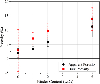
Figure 3. Both apparent (black circles) and bulk (red squares) porosity increase with increasing binder content. Bulk porosity values are consistently larger than apparent porosity, which could suggest porosity on the surface of the composites is less prominent than their internal porosity.
Download figure:
Standard image High-resolution imageThe surface structure and chemistry of LPSCl thin films were characterized using Raman mapping and unsupervised learning methods. A typical Raman mapping based on single peak intensity (e.g., 429 cm−1 for P-S stretch mode in PS4 3− representing LPSCl) is shown in Figs. 4a–4b. The Raman mapping based on single peak intensity revealed that both samples had LPSCl deficient locations. However, while Raman mapping based on single peak intensity can show the chemical distribution of a given species, it fails to reflect the relative distribution of multiple components and may miss important spectral features of the object. 24
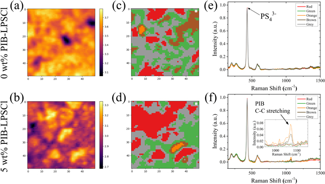
Figure 4. (a)–(b) Raman mapping scaled with the single peak intensity at 429 cm−1 (P-S stretch mode in PS4 3−) (c)–(d) Raman mapping based on K-means clustering analysis of each sample respectively in (a)–(b). (e)–(f) The centroid spectrum of each cluster with the same color code corresponding to (c)–(d) for each sample. Inset of (f) provides a magnified view of the C–C stretch mode centered at 1071 cm−1.
Download figure:
Standard image High-resolution imageTherefore, we employed K-means clustering analysis to distill information from the 2500 spectra in each mapping frame (50 × 50 μm2). We clustered the 2500 spectra of each Raman mapping into five groups for each sample, with each cluster representing a characteristic structure or chemistry and coded by a specific color (see "Experimental" for details) as shown in Figs. 4c–4d. The corresponding similarity loading maps are given in Fig. S4. The centroid spectrum of each cluster represented the characteristic features of all spectra in that category, as depicted in Figs. 4e–4f. The centroid spectra of the 0 wt% PIB-LPSCl exhibited featured Raman bands for the LPSCl, with a distinguished peak centered at 429 cm−1, overlapping with that of the pristine LPSCl powder. This indicates that LPSCl processed using toluene retains its structure. The P-S stretch mode is centered at 429 cm−1 for all clusters of the 5 wt% PIB-LPSCl samples, suggesting that the PIB binder addition did not disrupt the LPSCl structure. However, clusters orange and brown exhibited a peak at 1071 cm−1, likely attributed to the C–C stretch mode of the PIB polymer binder. The size of these two clusters was on the scale of 10 μm, consistent with the structural defect observed from the SEM micrograph shown in Fig. 2. Thus, the K-means clustering analysis of the Raman mapping demonstrated that the solution processing by toluene with the PIB binder did not change the LPSCl structure. However, the addition of the PIB binder led to local phase segregation due to immiscibility between the binder and LPSCl.
Pressure- and temperature-dependent ion transport
The relaxation of the polymer binder may affect the percolation of ion-transport pathways through the free-standing LPSCl thin film under different compressive stress values. While the pressure-dependent ion transport properties have been well explored for cold-pressed sulfide SEs, studies of free-standing sulfide SE separators are lacking. 25 The pressure dependent ionic transport property can be elucidated by the impedance spectroscopy at various stack pressure values. The EIS was taken at a stack pressure of 20 MPa and again after decreasing the stack pressure to about 0.5 MPa. Upon decreasing the stack pressure, absolute resistance increased. This was to be expected since increased stack pressures are known to decrease resistance associated with interfacial contact within sulfide SE pellets. Nyquist plots of these samples are shown in Supplementary Fig. S5. At 0.5 MPa, 0 wt% PIB-LPSCl retained 64 ± 19% of its ionic conductivity at 30 MPa. 1 wt%, 2 wt%, and 5 wt% retained 49 ± 1%, 44 ± 2%, and 31 ± 2%, respectively.
To probe the pressure dependence of conductivity in more detail, a range of pressures was studied. Conductivity as a function of stack pressure is shown in Fig. 5a. Interestingly, the ionic conductivity of 5 wt% PIB-LPSCl showed a stronger dependence on stack pressure than the samples containing less binder. Such a phenomenon can be explained as follows. The non-polar PIB binder tends to distribute at the polar LPSCl grain boundaries due to the mutual exclusion between the two objects. As the PIB-LPSCl pellet was compressed, sulfide SE particles formed intimate contacts with one another to make Li+ percolation pathways. Consequently, PIB chains located between particles were deformed from their equilibrium conformations to accommodate the SE particles. As the compressive force was relieved, intramolecular repulsions drove the SE particles apart to allow for the deformed chains to minimize their free energy (i.e., maximize conformational entropy). This sulfide SE particle separation resulted in a loss of interparticle contact. Thus, ion conduction pathways were lost, and conductivity decreased to a greater extent than in samples with lower PIB content.
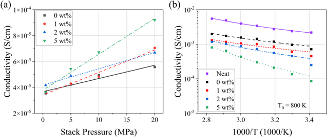
Figure 5. Conductivity as a function of (a) stack pressure (0.05–20 MPa) and (b) temperature (20 °C–80 °C). As stack pressure was reduced, 5 wt% PIB-LPSCl lost a larger portion of its conductivity at 20 MPa than the samples containing less binder. Activation energy of 5 wt% PIB-LPSCl was significantly greater than samples containing less binder. Treatment with toluene reduced conductivity at all measured temperatures. VFT fits are shown in (b) (— Neat, — — 0 wt%, ‒ ‒ 1 wt%, ‒·‒ 2 wt%, and ‥‥5 wt%). The ionic conductivity of samples shown in (a) is lower than those reported elsewhere due to their significantly lower fabrication pressure.
Download figure:
Standard image High-resolution imageThe results of the temperature-dependent ionic conductivity data and fits corroborate these findings. The activation energy of each sample was found by fitting experimental data to the Vogel-Fulcher-Tammann (VFT) equation. The VFT equation is given in Eq. 7 where σ0 is a prefactor, T is temperature, T0 is the Vogel temperature, and BR is the quantity Ea/R. Ea is the activation energy for ion conduction in the material, and R is the gas constant. 26

For polymer electrolytes, T0 represents the ideal glass transition temperature, the temperature at which configurational entropy is zero. 27 For inorganic SEs, T0 currently bears no physical meaning. 28 T0 was fixed at a value of 800 K, such that the Ea found for neat LPSCl was near 0.34 eV, a value previously found by Arrhenius-type fitting methods. 29,30 Arrhenius fits of collected conductivity data are shown in Fig. S6, and corresponding fit parameters are given in Table SI. The raw data is plotted with the fit results in Fig. 5b. The fit parameters, extracted activation energies, and R2 values are given in Table I.
Table I. Results of fitting conductivity data to Eq. 6 Σ0 is a pre-factor, T is temperature, T0 is the Vogel temperature, and BR is the quantity Ea/R. Ea is the activation energy of the material, and R2 is a goodness-of-fit statistic. 26
| PIB Content (wt%) | σ0 (S/cm) | BR (K) | T0 (K) | Ea (eV) | Ea (kJ/mol) | R2 |
|---|---|---|---|---|---|---|
| Neat LPSCl | 1.47 × 10⁻⁶ | 3690 | 800 | 0.32 ± 0.03 | 31 ± 3 | 0.991 |
| 0 | 1.52 × 10⁻⁶ | 3220 | 800 | 0.28 ± 0.07 | 27 ± 7 | 0.956 |
| 1 | 1.26 × 10⁻⁶ | 3120 | 800 | 0.27 ± 0.10 | 26 ± 10 | 0.895 |
| 2 | 6.28 × 10⁻⁸ | 4420 | 800 | 0.38 ± 0.08 | 37 ± 8 | 0.950 |
| 5 | 5.99 × 10⁻¹¹ | 7360 | 800 | 0.64 ± 0.10 | 61 ± 10 | 0.984 |
In addition to the samples containing toluene-treated LPSCl (0–5 wt% PIB-LPSCl), untreated LPSCl (neat LPSCl) was also tested as a control. According to the fit values, Ea of 0, 1, and 2 wt% PIB-LPSCl was not significantly different than that of the neat LPSCl. However, Ea of 5 wt% PIB-LPSCl was significantly greater than the other samples.
Li Stripping and plating tests
Li stripping/plating tests were conducted with Li@Cu symmetric cells in PEEK holders under an argon atmosphere at room temperature using one-hour charge/discharge cycles. The samples consisted of a neat LPSCl control cell (black), stacked flakes of 1 wt% PIB-LPSCl (gray), seven stacked layers of 2 wt% PIB-LPSCl thin film cell (blue), and two stacked layers of 5 wt% PIB-LPSCl thin film cell (red). The first ten cycles are shown in Fig. 6a, where the potential has been normalized by the pellet thickness (1.2 mm, 0.81 mm, 0.60 mm, and 0.25 mm for the neat LPSCl, 1 wt% PIB-LPSCl, 2 wt% PIB-LPSCl, and 5 wt% PIB-LPSCl, respectively). The 1 wt% PIB-LPSCl cell exhibited asymmetric polarization profiles and shorted fourth cycle. It is likely the lithium metal extruded partway through the mosaic-style pellet during fabrication due to the pellet's rough nature. The 5 wt% PIB-LPSCl thin film cell exhibited the largest magnitude overpotential due to greater electrolyte resistance within the composite. The 2 wt% PIB-LPSCl thin film cell exhibited an overpotential very similar to that of the neat LPSCl control.

Figure 6. Comparison of a 125 mg neat LPSCl electrolyte pellet and PIB-LPSCl electrolyte films for (a) the first ten cycles at 40 μA cm−2 and (b) critical current density test. In both cases, the potential, Ewe, has been normalized by the pellet thickness (0.12 cm, 0.060 cm, and 0.025 cm for neat LPSCl, 2 wt% PIB-LPSCl, and 5 wt% PIB-LPSCl, respectively).
Download figure:
Standard image High-resolution imageAfter the cells underwent 100 cycles at 40 μA cm−2, a critical current density (CCD) test was conducted. The results of this test are given in Fig. 6b. When the current density was increased to 80 μA cm−2, the PIB-LPSCl cells began to show instability. Upon increasing the current density to 118 μA cm−2, the PIB-LPSCl cells shorted in the first two cycles. At the same time, the neat LPSCl sample began to show increased polarization. During the following cycle at 118 μA cm−2, the neat LPSCl sample soft-shorted. Increased polarization preceding unstable polarization is known to be indicative of a contact-loss-driven short. 31 As Li metal is stripped, vacancy sites are generated at the Li/SE interface. As Li stripping continues, these vacancy sites accumulate, forming larger pores. The effective interfacial area is thereby decreased, leading to increased current density in the areas remaining intact. This phenomenon has been reported previously. 32,33 An illustrated example of void induced short circuit mechanism is shown in Fig. 7. It is not immediately clear how the 2 wt% PIB-LPSCl cell failed. The Nyquist plots before and after cell failure are given in Supplementary Fig. S8. The CCD of the neat LPSCl was found to be 118 μA cm−2. Potential strategies to increase the CCD include the use of an interlayer between the Li metal and SE and the use of lithiophilic composite anodes. 34–36 For example, Wu et al. found current density at the Li/SE interface was homogenized by including a thin silver-carbon composite interlayer, which improved cycling stability against Li metal. 3

Figure 7. Illustrated mechanism of void-induced short circuit. Heterogeneous SE/anode interfacial composition leads to uneven current distribution, resulting in dendrite growth.
Download figure:
Standard image High-resolution image
Discussion
Free-standing, thin films were fabricated using slurry-based tape-casting methods, and the results revealed that even small quantities (∼2 wt%) of a non-polar binder could yield robust thin separators. A correlation was found between binder mass loading and both bulk and surface porosity. We postulate the weak interactions of the non-polar binder with the sulfide SE particles result in discrete pockets between sulfide SE particles, thus inhibiting the formation of long-lasting ion percolation pathways during fabrication. These pockets consist of void space and ionically insulating PIB. The first piece of evidence for this was shown by the greater dependence of conductivity on stack pressure for 5 wt% PIB-LPSCl in comparison with the samples with lower binder mass loadings. The 5 wt% PIB-LPSCl retained only about 40% of its conductivity at 0.5 MPa, as compared to that at 20 MPa. In contrast, the conductivity of 0 wt% PIB-LPSCl showed the weakest dependence on stack pressure and retained over 65% of its conductivity on going from 20 MPa to 0.5 MPa. The second piece of evidence was the significantly greater activation energy of 5 wt% PIB-LPSCl over the other samples. The presence of an insulating phase between superionic particles, whether that phase is binder or void space, led to increased activation energy. Interestingly, these effects only became significant at binder loadings of 5 wt%. The reason behind this threshold remains unclear.
Importantly, the correlation between porosity and binder mass loading has implications for stability against Li dendrite growth, as demonstrated with Li symmetric cell cycling. In the case of the 5 wt% PIB-LPSCl cell, surface inhomogeneity results in a distribution of current densities and Li+ diffusion coefficients at the Li metal interface. 31 Internal porosity has been shown to lower critical current density, and dendrite penetration can be induced by such internal defects. 37,38 In terms of critical current density, the 2 wt% PIB-LPSCl and 5 wt% PIB-LPSCl thin film cells showed signs of instability at nearly the same time and current density as the neat LPSCl control. This was unexpected, considering the different porosity in the two samples. However, as shown in Fig. S8, they failed by different mechanisms (dendrite penetration for the 5 wt% PIB-LPSCl and contact loss for neat LPSCl). The combination of increased surface defects seeding dendrite growth and reduced dendrite propagation distance (i.e., film thickness) were ultimately the limiting factors for the thin film's critical current density. These results demonstrate the importance of mitigating surface defects on thin film separators. The use of a binder slightly more polar than PIB, a solvent with a greater vapor pressure than toluene, or a solvent-binder combination with less favorable cross-interaction than PIB and toluene would all be valid approaches to mitigate these surface defects. 12,39
Conclusions
In this study, we explored the effects of PIB, a non-polar binder, on the morphology and electrochemical performance of 0, 1, 2, and 5 wt% PIB-LPSCl composite separators. Free-standing films could be fabricated with as little as 1 wt% binder, but 2 wt% binder was required for consistent film quality. Films with 5 wt% binder exhibited the greatest mechanical robustness. The ionic conductivity was found to be dependent on stack pressure and temperature. We postulate this is due to the binder forming insulating pockets between sulfide SE particles, thus inhibiting the formation of long-lasting ion percolation pathways during fabrication. The inclusion of the binder at 5 wt% loading allowed for the fabrication of an order of magnitude thinner separator, but it also increased the separators' interfacial resistance, surface porosity, and activation energy for ion conduction. Our findings highlight the importance of the selection of slurry components, including sulfide SE, binder, and solvent, as well as the importance of electrolyte/electrode interfacial stability in the development of thin film sulfide SEs. To develop high-performance electrolyte composite materials capable of achieving ideal form factors, an intimate understanding of constituent cross- and self-interactions warrants further pursuit. For example, the development of novel techniques, such as a method to characterize surface energetics of ionic solids, would prove beneficial in a field dominated by trial-and-error testing. Finally, given the ubiquitous nature of polymer binders in composite thin films, careful consideration of binder properties, such as chain length, which we intend to investigate in a future publication, must be included in optimization studies.
Acknowledgments
This research was conducted at Oak Ridge National Laboratory, managed by UT Battelle, LLC, for the U.S. Department of Energy (DOE) and is sponsored by the Office of Energy Efficiency and Renewable Energy (EERE) in the Vehicle Technologies Office (VTO) through the Advanced Battery Materials Research (BMR) Program. This manuscript has been authored by UT-Battelle, LLC under Contract No. DE-AC05–00OR22725 with the U.S. Department of Energy. SEM measurement was conducted as part of a user project at the Center for Nanophase Materials Sciences (CNMS), which is a US Department of Energy, Office of Science User Facility at Oak Ridge National Laboratory. We would like to thank Ethan Self, Teerth Brahmbhatt, Frank Delnick, and Andrew Westover for their fruitful discussions. The United States Government retains and the publisher, by accepting the article for publication, acknowledges that the United States Government retains a non-exclusive, paid-up, irrevocable, world-wide license to publish or reproduce the published form of this manuscript, or allow others to do so, for United States Government purposes. The Department of Energy will provide public access to these results of federally sponsored research in accordance with the DOE Public Access Plan. (http://energy.gov/downloads/doe-public-access-plan).
Supplementary data (1.2 MB PDF)