
Abstract
Improving utilization, performance, and stability of low iridium (Ir)-loaded anodes is a key goal to enable widespread adoption of polymer electrolyte membrane water electrolysis (PEMWE) for clean hydrogen production. A potential limitation is high ionic or electronic resistance of the anode catalyst layer, which leads to poor catalyst utilization, increased voltage losses, and high local overpotentials that can accelerate degradation. While catalyst layer resistance is relatively well-understood in fuel cells and other porous electrode systems, characterization of these effects is not as well established in PEMWE research. Here we present in-situ methods for measuring catalyst layer resistance in electrolysis cells using a non-faradaic H2/H2O condition as well as methods for calculating the associated voltage losses. These methods are applied to anode catalyst layers based on IrO2 nanoparticles as well as dispersed nano-structured thin film (NSTF) Ir catalysts. Trends with anode catalyst loading and interactions between the porous transport layer and catalyst layer are investigated for IrO2 anodes. Post-mortem microscopic analysis of durability-tested anodes is also presented, showing uneven degradation of the catalyst layer caused by catalyst layer resistance.
Export citation and abstract BibTeX RIS

This is an open access article distributed under the terms of the Creative Commons Attribution 4.0 License (CC BY, http://creativecommons.org/licenses/by/4.0/), which permits unrestricted reuse of the work in any medium, provided the original work is properly cited.
Hydrogen production by electrolysis has great potential to enable a decarbonized economy, although further effort is needed to decrease its cost. 1,2 Meeting hydrogen production cost targets such as the US Department of Energy Hydrogen Earthshot goal of $1/kgH2 3 will require improvements to electrolyzer devices to enable highly efficient hydrogen production, long lifetimes, and low capital costs, including minimizing use of scarce materials such as platinum group metals (PGMs). 4,5 Proton exchange membrane water electrolysis (PEMWE) combines several attractive attributes for production of clean hydrogen at scale, including high current density and efficiency, good hydrogen purity, differential pressure operation, and suitability for dynamic operation such as direct integration with low-cost renewable energy sources or load-balancing applications. 2,6 Compared to alkaline electrolysis, which has been commercialized at large scale for around a century, PEMWE is a relatively less mature technology with many opportunities for further improvement. 2 In PEMWE, the anode catalyst layer is a critical component because of the challenging kinetics of the oxygen evolution reaction (OER) which limit overall cell efficiency. Further, the highly oxidizing and acidic conditions of the OER anode necessitate the use of expensive and scarce Iridium (Ir)-based catalysts and PGM coatings. For PEMWE to achieve production cost and volume targets, it is essential to develop low-PGM-loaded anodes that maximize catalyst utilization, minimize voltage losses, and mitigate degradation of the catalyst layer. 2,4,5,7,8
The resistivity of the anode catalyst layer is an important property impacting the overall effectiveness of the electrode, 2 and catalyst layer resistance (CLR) effects have been a topic of significant interest for the PEMWE research community. 9–20 In general, the internal resistance of the anode catalyst layer leads to ohmic losses as current passes through it, lowering the overpotential driving the OER. At high current density this leads to loss of catalyst utilization, higher voltage losses, and an uneven distribution of current. 2,21 Depending on the design of the anode–including catalyst loading, ionomer content, and the PTL interface–either ionic or electronic resistance may dominate, with electronic resistance potentially being both in-plane and through-plane, 9,10,12 as illustrated in Fig. 1.
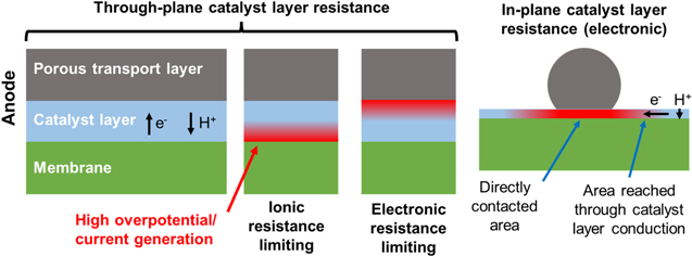
Figure 1. Illustration of types of catalyst layer resistance that can be present in PEMWE catalyst layers. The diagrams at the left illustrate the case where the limiting conduction is primarily through-plane, with the porous transport layer approximated as a continuous slab. Regions of high local overpotential and OER current generation resulting from the limiting resistance in the catalyst layer are shaded in red. In the case where ionic resistance or electronic resistance is limiting, most current generation occurs near the membrane/catalyst layer interface or PTL/catalyst layer interface, respectively. The diagram at the right illustrates the case where the limiting conduction is primarily in-plane, i.e., for thin, electronically resistive catalyst layers and coarse PTL structures. In this case electronic current in the catalyst layer passes in-plane from regions of contact to PTL fibers or particles into regions of PTL pores.
Download figure:
Standard image High-resolution imageA powerful tool for understanding these phenomena is available through porous electrode theory, which has been extensively developed for electrochemical systems in general. 21–27 An electrolyzer anode catalyst layer can be modeled as a transmission line, with the proton-conducting ionomer phase and the electron-conducting solid phase connected by the capacitive, catalytically active catalyst surface across a spatially extended region. 14–17,21 Such a transmission line model can be used for both in-situ measurement of the catalyst layer resistance and determination of the resulting voltage losses. This approach has found widespread application for PEM fuel cells 21,28–31 where impedance measurement of the cathode catalyst layer resistance (typically done under a non-faradaic H2/N2 (anode/cathode) condition) is used to determine utilization and voltage losses.
Impedance-based quantification of utilization and voltage losses from catalyst layer resistance has not yet become a routine diagnostic tool for PEMWE, despite the potential value demonstrated by its application in PEM fuel cells. Several prior studies have included ex-situ measurements of electronic and ionic resistance in catalyst layers and powders 9,12,13 or performed transmission-line impedance analysis of catalyst layer resistance. 14–17,19 Babic et al. 19 used transmission line impedance to measure CLR (that they assumed to be ionic) and quantified voltage losses based on an Ohmic approximation, which is suitable at low current density but neglects the utilization effects that are dominant at high current density, as we will discuss. Bernt et al. 10,18 calculated voltage losses from ionic CLR including utilization effects, although using ionic electrode resistances estimated from microscopic analysis rather than in-situ measurement by impedance. In this work, we demonstrate methods for simple transmission-line impedance-based quantification of utilization and voltage losses from catalyst layer resistance, including both ionic and electronic resistance.
Some practices for experimental voltage loss breakdown analysis are commonly used in the PEMWE research community to identify thermodynamic, ohmic, and kinetic voltage losses. 10,32–38 The thermodynamic voltage is generally estimated theoretically based on standard reaction potentials with Nernst corrections for the operating temperature, pressure, and reactant/product concentrations. 39 The ohmic voltage, including all ohmic losses from the membrane, contact resistances, and bulk resistances of the diffusion media, is calculated using measurements of the high-frequency resistance (HFR) from impedance spectroscopy. A Tafel fit is then applied to the HFR-free voltage minus the thermodynamic voltage at low current densities to determine losses from OER kinetics. Because of the extremely fast kinetics of the hydrogen evolution reaction on Pt catalysts, cathode kinetic losses are commonly assumed to be on the order of a few mV and are neglected. This procedure generally leaves some leftover voltage at high current densities, which may include losses from water/oxygen mass transport, catalyst layer resistance, and effects from ionic contaminants. Researchers commonly lump all these residual losses as "mass transport" losses despite the difference in their root causes. In order to make targeted improvements in PEMWE performance and durability, it is important to distinguish and quantify these different sources of voltage loss. Fortunately, catalyst layer resistance losses can easily be determined using impedance spectroscopy and porous electrode theory to include in voltage loss breakdown analysis.
This paper demonstrates in-situ methods for characterizing catalyst layer resistance in PEMWE cells and determining the impacts on catalyst utilization and voltage losses. In fuel cells, analogous characterization is done under a H2/N2 (anode/cathode) condition, which ensures a non-faradaic condition while closely reflecting the gas-phase operating conditions of the fuel cell. While H2/N2 (cathode/anode) conditions can also be used in electrolyzers for diagnostic purposes, we make in-situ measurements of the catalyst layer resistance using a H2/H2O (cathode/anode) condition, which more closely reflects the liquid-saturated operating conditions of the PEMWE, and is therefore more useful as a direct predictor of operating voltage losses. Non-faradaic conditions are ensured by controlling the cell voltage between OER and ORR onset potentials. We review the theory of utilization and voltage losses caused by catalyst layer resistance and provide simplified approximations to facilitate routine voltage loss breakdown analysis, which are implemented in a spreadsheet calculator provided in the Supplemental Information. We also apply these methods to analyze two different anode catalyst layer systems: 1) a dispersed nanostructured thin film (NSTF) catalyst layer and 2) IrO2 catalyst layers, including investigation of the impact of catalyst layer loading and interactions with the porous transport layer (PTL). Finally, we present the results from post-mortem analysis of durability-tested anodes using scanning transmission electron microscopy (STEM) to show how high in-plane electronic resistance can lead to more rapid and uneven degradation. The methods presented here are relatively simple to incorporate into routine PEMWE cell testing and provide significant diagnostic value for voltage loss breakdown to inform deeper understanding of electrolyzer anodes.
Methods
Cell materials and fabrication
The Future Generation Membrane Electrode Assembly ("FuGeMEA") cell configuration is a standard set of cell components used by the U.S. Department of Energy's H2NEW consortium. 40 It consists of a Nafion N115 membrane, a Pt/C cathode catalyst layer, IrO2 anode catalyst layer, cathode gas diffusion layer (AvCarb MGL280) at approximately 20% compression, and a Pt-coated titanium felt anode PTL (Bekaert 2GDL10N, 56% nominal porosity). Variations on this configuration were used here to explore the effect of the anode catalyst loading and catalyst layer/PTL interactions, as noted in the results section. The different PTL materials tested here included 1) "59% Porosity Fiber PTL": Bekaert 2GDL10N, Pt-coated Ti fibers, 56% nominal porosity, 59% porosity by measured weight and thickness, 2) "74% Porosity Fiber PTL": Bekaert 2GDL05N, Pt-coated Ti fibers, 77% nominal porosity, 74% porosity by measured weight and thickness, 3) "Sinter PTL": Plug Power Inc., Pt-coated Ti sinter, 43% porosity by measured weight and thickness. The standard FuGeMEA materials were used wherever not specified.
Catalyst coated membranes (CCMs) for the FuGeMEA cells were fabricated by ultrasonic spray coating directly onto Nafion N115, with the cathode catalyst layer coated before the anode catalyst layer. The cathode catalyst layer contained Pt on high surface area carbon (Pt/HSC, Tanaka Kikinzoku Kogyo, TEC10E50E) with a targeted ionomer (Nafion D2020) to carbon ratio of 0.45:1, with a targeted catalyst loading of 0.1 mgPt cm−2. The ink for cathode spray coating was prepared at a concentration of 1 mgPt ml−1 in a solution of DI water and n-propyl alcohol (nPA) at a ratio of 1:0.95 (water:nPA), pre-chilled with ice, and mixed for 30 s in a probe ultrasonicator, followed by 15 min in an ice-water-filled bath ultrasonicator. Anode catalyst layers contained unsupported Ir oxide (Alfa Aesar) with an ionomer (Nafion D2020) to catalyst ratio of 0.27:1. The ink for anode spray coating was prepared at a concentration of 2.75 mgIr ml−1 in a solution of DI water and n-propyl alcohol (nPA) at a ratio of 1:0.95 (water:nPA), pre-chilled with ice, and mixed for 2 min in a probe ultrasonicator, followed by 30 min in an ice-water-filled bath ultrasonicator. After spray-coating, CCMs were flattened by soaking in DI water and drying on a vacuum table overnight.
Catalyst loadings were measured by XRF (Fischer XDV-SDD). The cathode catalyst loading was 0.11 ± 0.01 mgPt cm−2 for all CCMs used for FuGeMEA voltage loss breakdown analysis and investigation of PTL/catalyst layer interactions and anode loading effects. The durability-tested CCM used for post-mortem microscopic analysis had a cathode catalyst loading of 0.08 ± 0.01 mgPt cm−2. Anode loadings for each sample are specified in the results section.
The Ir-NSTF CCM and cell components were provided by 3M. The CCM was prepared by a developmental roll-to-roll lamination process. 41 The anode electrode consisted of Ir-NSTF catalyst powder (nominally 88 wt% Ir) and 3M 725EW PFSA ionomer (nominally 0.15 ionomer to catalyst ratio by weight) with an Ir loading of 0.25 mg cm−2 and was prepared by a roll-to-roll coating process. The cathode electrode was analogous to the anode electrode but consisted of Pt-NSTF catalyst powder (nominally 78 wt% Pt) and the Pt loading was 0.09 mg cm−2. The membrane consisted of 3M 800EW ionomer, contained a recombination catalyst, and was approximately 92 μm thick. The anode PTL was a platinized Ti sinter prepared by Plug Power, Inc. and the cathode GDL was Freudenberg H2C2.
Electrolyzer cell testing
All electrolyzer cell tests were conducted using an in-house constructed electrolyzer test station and custom hardware. The test hardware accommodates 5 cm2 and 25 cm2 active areas and has triple-serpentine, Pt/Au (anode/cathode) coated titanium flow fields. All cells were operated in a dry-cathode condition with an anode flow rate of 50 ml min−1 at 80 °C with the water temperature controlled by a thermocouple at the anode inlet. The cell temperature was also regulated by heater pads placed on the hardware end plates, which were controlled by a thermocouple inserted into the anode flow field. Before performance testing, all cells were conditioned by a combination of current/voltage holds and polarization curves until stable performance was observed in repeated polarization curves. Conditioning and durability testing used electrical power from the test station load bank, while performance and impedance data reported in the paper were all recorded using an Autolab potentiostat/galvanostat with a 20 A booster (PGSTAT302N, Metrohm).
Non-faradaic, transmission-line impedance curves were recorded potentiostatically at 1.25 V. This voltage was chosen to ensure that there is no faradaic current passing through the cell while also ensuring that the catalyst remains in an oxidized state that is relatively representative of the conditions during oxygen evolution. This measurement requires hydrogen presence on the cathode to establish a reference/counter electrode, which can be provided by either flowing humidified hydrogen over the cathode or using the residual hydrogen from a recently operated cell. In this work, residual hydrogen was generated using a 5 min hold at 0.2 A cm−2, followed by a 2 min hold at 1.25 V to stabilize the cell prior to measurement of the impedance spectrum. Each of these methods has advantages and potential drawbacks, and their stability is compared in Fig. S4 and discussed in more detail in the supplemental information. Flowing hydrogen guarantees a stable reference/counter electrode, although extended periods with flowing hydrogen can impact the anode catalyst layer through reaction with crossover hydrogen diffusing through the membrane, 42 which has been observed by the authors. Residual hydrogen has lower risk of invasively altering the catalyst layer and is experimentally convenient, although measurements should be taken quickly (within a few minutes) after generating the hydrogen to ensure that the cathode potential does not drift. Under most circumstances, a single impedance curve measured under either of these conditions will be identical in the relevant frequency range needed for analysis. All data presented here were recorded using the residual hydrogen condition.
Numerical calculations and data analysis
Numerical calculations and data processing were done in Matlab. Numerical differential equation solution used the bvp4c function using the equations and boundary conditions detailed in the Theory section. Linear fits used the polyfit function, while other curve fits used fminsearch in the optimization toolbox, which uses a Nelder-Mead simplex optimization algorithm.
A Monte Carlo approach was used to determine the numerical factors and errors for the approximations in Eqs. 11 and 12. Voltage losses were calculated for randomly selected values of the Tafel slope, exchange current density, and catalyst layer resistance. The numerical factors were selected and validated in two rounds, each with 1000 runs. In the first round, the best fit numerical factor was calculated to minimize the mean squared error for each run independently. In the second round, the average numerical factor (reported in the paper) was used for all runs to determine the average and maximum errors. The maximum error was the largest error for any single point in all 1000 runs.
For experimental voltage breakdown analysis, the HFR was calculated by interpolation of the Nyquist curve to find the real axis intercept. Experimental Tafel plots include a short-circuit-current correction to the current density, which impacts points at very low current density (≲10 mA cm−2). A short-circuit resistance was calculated from the current density at 1.25 V (where effectively zero electrochemical current is expected; this is recorded at the end of the stabilization period after residual hydrogen generation) and used to calculate the short-circuit current at each current/voltage point in the pol curve according to Ohm's law. This short-circuit current was subtracted from the current density in the Tafel plots. Short circuit currents ranging from 0 to 1 mA cm−2 were measured for the cells tested in this work. The source of this current is not precisely known but may result from either imperfect electrical insulation in the cell test hardware or internally from points where imperfections in the PTL and GDL may protrude into the membrane. Some current may be due to oxidation of crossover hydrogen from the cathode as well; while this would not be due to short circuit current, it is appropriate to correct for it similarly in Tafel analysis.
Transmission electron microscopy
Post-mortem CCM specimens were embedded in epoxy resin and then cut by diamond-knife ultramicrotomy, targeting a thickness of ∼75 nm. High-angle annular dark-field scanning transmission electron microscopy (HAADF-STEM) and energy-dispersive X-ray spectrum (EDS) images were recorded using a Talos F200X transmission electron microscope (TEM, Thermo Fisher Scientific) operated at 200 kV and equipped with Super-X EDS system with 4 windowless silicon drift detectors.
Theory
General overview
The theory of resistivity in porous electrodes has been thoroughly investigated in previous literature for general electrochemical devices 21–25 and PEM fuel cells. 12–15 Here we will briefly recap the relevant theory in the context of PEM electrolysis, including numerical calculations to illustrate important trends.
In the PEM electrolyzer anode, the OER generates oxygen, protons, and electrons from water:  Electrons pass across the catalyst surface and leave the anode through electronically conductive pathways in the catalyst layer and PTL. Protons travel through the ionic phases (especially ionomer) in the catalyst layer to the membrane. If there is significant ionic or electronic resistance in the catalyst layer, this conduction will lead to ohmic drops that cause the local overpotential driving the OER to vary across the catalyst layer.
To begin, we assume negligible electronic resistance in the catalyst layer so that ohmic drops only impact the ionic potential. For either through-plane or in-plane electronic resistance, the overall voltage and utilization losses are identical to the case of ionic resistance with differences only in the resulting distribution of current (as illustrated in Fig. 1).
Porous electrode theory models the distribution of current and potential across the catalyst layer as shown in Fig. 2a. The most common form of the classical model describes the catalyst layer as a slab of solid, electronically conducting material containing cylindrical pores filled with ionically conducting electrolyte. For clarity, here we will avoid the use of unknown geometric properties of the catalyst layer, using only values that can be measured through impedance and kinetic parameters. It is convenient and equivalent to assign the catalyst layer unit length and describe its resistance and capacitance with continuous averages (the "macrohomogeneous" model" 27,43 ) in terms of empirically measurable quantities.

Figure 2. Illustration of the impact of catalyst layer resistance using numerical calculations. (a) Schematic of the catalyst layer showing the electrolyte phase in green and the electronically conducting phase in grey, with the ionic current  ionic overpotential
  and electronic overpotential
  indicated.
  denotes the membrane/catalyst layer interface and
  denotes the catalyst layer/PTL interface. (b) Nyquist plot of corresponding impedance curve under a non-faradaic condition. (c) Distribution of OER overpotential
  locally generated OER current
  and cumulative ionic current
  as a function of position in the catalyst layer (CL) for 10 mA cm−2 and 1 A cm−2 total cell current density. (d)-(e) Semi-log plots showing the total voltage drop across the catalyst layer (d), the voltage losses caused by catalyst layer resistance, and the catalyst utilization (e) as a function of current density, with the Tafel and semi-infinite pore limits indicated in (d) alongside the simple Ohmic approximation.
Download figure:
Standard image High-resolution imageFor a catalyst layer with unit length (extending from  to
to  ) and a total series resistance of
  (this is the quantity measured by transmission line impedance), ionic current
  will lead to an ohmic drop in the ionic potential
  according to:

Impedance of porous electrodes is typically described under a non-faradaic condition with zero direct current:

Where  is the capacitive impedance of the catalyst surface, either assumed as an ideal capacitor
  with imaginary number
  capacitance
  and angular frequency
  or as a constant phase element
  with parameters
  and
and  This purely capacitive system is equivalent to a simple transmission line, giving rise to the classic transmission line impedance illustrated in Fig. 2b with the overall impedance:

which has been simplified using the convenient parameterization  Nyquist plots of this impedance show a distinctive shape, with a high frequency region having a 45° slope and a width of
  transitioning to a vertical (or high constant phase) region at lower frequency. The catalyst layer resistance
  can easily be measured from such a curve, either by fitting to Eq. 3 or by a graphical measurement of the width of the 45° region in the Nyquist plot. Multiple impedance fitting tools are available for this purpose, including, for example, commercial programs and the Open Source Impedance Fitter (OSIF).
44
can easily be measured from such a curve, either by fitting to Eq. 3 or by a graphical measurement of the width of the 45° region in the Nyquist plot. Multiple impedance fitting tools are available for this purpose, including, for example, commercial programs and the Open Source Impedance Fitter (OSIF).
44
An important caveat is that a 45° slope is expected only if the conductivity and capacitance are uniform across the catalyst layer; variations in the ratio of conductivity to capacitance (such as resulting from different pore shapes) can alter the slope or add curvature to this region,
21,45
although the width of this region before the transition to simple capacitive behavior is still generally  for the effective total resistance
  As demonstrated by Qi et al.,
46
transmission line impedance does not necessarily measure the same
As demonstrated by Qi et al.,
46
transmission line impedance does not necessarily measure the same  as ex situ methods such as hydrogen pump (HP) techniques. This is because HP will include only the ionic pathways that pass continuously through the entire catalyst layer through-plane, while impedance will measure all ionic (or electronic) pathways that are connected to the membrane (or PTL), leading to lower
  values from impedance. However, the pathways measured by impedance are those that contribute to the DC conductivity of catalyst layers functioning in-situ, and therefore the
  measured by transmission line impedance is appropriate for performance prediction.
For an electrolyzer anode under direct current, the right-hand side of Eq. 2 must instead be replaced by a kinetic expression for the OER. Either the Tafel approximation with exchange current density  and Tafel slope
  or a hyperbolic sine (sinh) function approximating Butler-Volmer kinetics is suitable:

Equations 2 and 4 plus the boundary conditions 
 present a system of differential equations that can be solved for voltage losses of the catalyst layer as a function of the total cell current
  23
23
For Tafel or Butler-Volmer kinetics, these equations do not have a simple analytical solution, although the general trend in voltage losses  is straightforward. There are two well-defined limits to the
  relation that have analytical solutions: the Tafel limit (Eq. 5) and the semi-infinite pore limit (Eq. 6).
23
At very low current density, the Ohmic effects of the catalyst layer resistance are negligible, and so the Tafel equation applies:
relation that have analytical solutions: the Tafel limit (Eq. 5) and the semi-infinite pore limit (Eq. 6).
23
At very low current density, the Ohmic effects of the catalyst layer resistance are negligible, and so the Tafel equation applies:

For high current densities, the Ohmic drop across the catalyst layer is large enough that the OER current density is negligible at some distance through the catalyst layer, giving the catalyst layer a "semi-infinite" effective length. This is the semi-infinite pore limit: 23

Notably, in this limit a Tafel-like form still applies, but with a different effective exchange current density and a doubled effective Tafel slope.
23,26,47,48
Here we have simplified the right-hand expression using  which is the current where the transition between these two limits occurs and where Eqs. 5 and 6 intercept:

This transition current, depending on just  and the Tafel slope
  also serves as a useful indicator of the onset of significant voltage losses from catalyst layer resistance.
Figures 2c–2e illustrate these trends using a numerical solution to the differential equations in Eqs. 2 and 4, assuming  Ω cm2,
  mV decade−1, and
  nA cm−2. Figure 2c shows the distribution of the OER overpotential, the OER current generation, and cumulative ionic current as a function of position in the catalyst layer. For low current densities in the Tafel limit, (e.g., 10 mA cm−2,) the ohmic drop from
  is negligible, so the overpotential and locally generated OER current remain approximately constant across the catalyst layer, and the cumulative current is a linear function. For high current densities in the semi-infinite pore limit, (e.g., 1 A cm−2,) a significant Ohmic voltage drop occurs across the catalyst layer. This causes the overpotential to vary and the current generation to occur primarily near the catalyst layer/membrane interface.
Figure 2d shows the total voltage drop across the catalyst layer as a function of current density,  on a semi-log Tafel plot. The transition between the Tafel limit at low current density and the semi-infinite pore limit at high current density occurs around
  which spans roughly ∼1–2 decades of current density. Figure 2e shows the voltage loss specifically caused by catalyst layer resistance,
  This excess loss is caused by a drop in the catalyst utilization

Where the utilization is defined as  The utilization must obey the following limits:

In Fig. 2e the catalyst utilization has sigmoidal shape on a semi-log plot, transitioning to exponential decay in the semi-infinite limit.
At low current density, losses due to catalyst layer resistance can be approximated to first order as Ohmic because the distribution of current across the electrode ( in Eq. 1) does not vary significantly with the overall current density:
19,49
in Eq. 1) does not vary significantly with the overall current density:
19,49

This approximation is sometimes used for the quantification of voltage losses, but because it neglects utilization effects it is only valid for low current densities  For
For  this approximation can dramatically overestimate
  as shown in Fig. 2d because decreasing utilization leads to a shorter conduction pathway and a lower effective resistance.
29
At
as shown in Fig. 2d because decreasing utilization leads to a shorter conduction pathway and a lower effective resistance.
29
At  where
where  10 mV, this approximation has an error of around 20%. Therefore, whenever significant losses from catalyst layer resistance are present, utilization effects should be considered and Eq. 10 is not valid.
Approximations of current-voltage relationship
Prior works have used numerical solutions, special functions, or root finding to predict voltage losses from catalyst layer resistance,  21–23,29,45
However, these approaches can be cumbersome for routine use in voltage loss breakdown analysis. Here we will present simple functions that closely approximate
21–23,29,45
However, these approaches can be cumbersome for routine use in voltage loss breakdown analysis. Here we will present simple functions that closely approximate  and
and  with the goal of simplifying the use of CLR characterization for voltage loss breakdown analysis. The approximations presented here are quantitatively equivalent to the "equivalent resistance" approach presented by Neyerlin et al.,
29
although they have the advantage that they are relatively simple to use. Both approximations are implemented in a spreadsheet calculator available in the supplementary information.
with the goal of simplifying the use of CLR characterization for voltage loss breakdown analysis. The approximations presented here are quantitatively equivalent to the "equivalent resistance" approach presented by Neyerlin et al.,
29
although they have the advantage that they are relatively simple to use. Both approximations are implemented in a spreadsheet calculator available in the supplementary information.
A suitable approximation must approach the Tafel and semi-infinite pore limits described above, with a smooth transition around  as shown in Figs. 2d, 2e. The main undefined parameter is the "width" of the transition region, which is determined through numerical simulations with a Monte Carlo approach.
The approximation for  is most easily phrased in terms of
  which must follow the sigmoid form visible in Fig. 2d. One suitable function is a modified logistic function with scaling parameter
  allowing adjustment of the width of the transition region while obeying the limits in Eq. 9:

Where the uncertainty in the least significant digits of  is indicated in parentheses. Together with Eq. 8, the approximation in Eq. 11 can approximate
  A N = 1000 Monte Carlo analysis (varying
 and
and  ) was used to identify the optimum value of
  With the above value, this approximation had an average (RMS) error of 0.7 mV in
  and 0.010 in
  with overall maximum errors of 2.2 mV and 0.018.
An approximation for  can be formed by combining Eqs. 5 and 6 with an operation to create a smooth transition:

With the above value of  determined in a similar N = 1000 Monte Carlo analysis, this approximation had an average (RMS) error of 0.2 mV in
  with overall maximum error of 0.5 mV.
For general voltage loss breakdown analysis, 1 mV precision is adequate and smaller than experimental error. Equations 11 and 12 can therefore be used as simple formulas to predict the impacts of catalyst layer resistance on cell performance.
Concurrent electronic and ionic resistance
Previous sections focused on a catalyst layer with resistance only in the ionic phase for conceptual simplicity. However, in general the electrolyzer catalyst layer will have resistance in both electronic and ionic phases. As we will demonstrate, the methods presented here also apply to catalyst layers with significant resistance only in the electronic phase or with significant resistance in both phases. These situations primarily differ only in the spatial distribution of current and overpotential across the catalyst layer.
Resistance in both electronic and ionic phases can be considered by modification of Eq. 1 to track the electronic and ionic current densities 
 and catalyst layer resistances
 assuming purely through-plane conduction:

Figures 3a–3c shows current and potential distributions calculated by numerical solution of the resulting system of equations, as before with  denoting the membrane/catalyst layer interface and
  denoting the catalyst layer/PTL interface. As noted above, with ionic resistance only (Fig. 3a), the overpotential is highest near the membrane, and so the catalyst layer is most utilized in this region. The distributions are mirrored with purely electronic resistance (Fig. 3c), which has the highest overpotential and utilization near the PTL. A catalyst layer with both ionic and electronic resistance (Fig. 3b) shows a distinct pattern, with both electronic and ionic potentials varying across the catalyst layer, resulting in a relatively flat overpotential. However, the overall "tilt" of both
  and
and  creates a more ohmic behavior and limits the utilization-driven effects described previously, which impacts both the impedance and voltage losses.

Figure 3. Catalyst layer resistance effects considering resistance in both ionic and electronic phases. (a)-(c) Distribution of current and potentials in catalyst layers at 1 A/cm2 showing (a) only ionic resistance ( Ω cm2,
  ), (b) both ionic and electronic resistance (
 Ω cm2,
  Ω cm2), and (c) only electronic resistance (
 Ω cm2), with
  denoting the membrane/catalyst layer interface and
  denoting the catalyst layer/PTL interface. (d) Nyquist plots of the non-faradaic transmission line impedance corresponding to the same catalyst layers in (a-c). (e) Semi-log Tafel plots of the voltage losses from the same catalyst layers. Open circles correspond to the HFR-corrected voltage losses from the electrode with resistance in both phases, using the HFR measured from the transmission line impedance in (d). The purple line shows the losses predicted from the width of the impedance curve in (d) after HFR correction, assuming the model for a single-phase resistance.
Download figure:
Standard image High-resolution imageA description of the transmission-line impedance considering both electronic and ionic resistance has been published in previous literature, 22,27,50 and is a more complex form of Eq. 3:

With  This equation is symmetric with respect to
  and
and  meaning that the electronic and ionic resistances cannot be distinguished by a single impedance spectrum alone. Identifying the primary and possible secondary resistances can instead be approached through experiments that vary operating conditions (such as temperature and humidity) and cell design (such as catalyst layer thickness, PTL geometry, or ionomer content), or by comparison to ex-situ measurements that can measure electronic and ionic resistances individually.
Figure 3d shows example Nyquist curves illustrating the impedance of catalyst layers with pure electronic or ionic resistance, or with both. While the impedance of a catalyst layer with either pure electronic or pure ionic resistance is identical, adding resistance in both phases narrows the curve and shifts it to higher real impedances. This is a notable and perhaps counterintuitive result, as adding resistance in a second phase lowers the apparent CLR but increases the HFR.
Fortunately, measurement of HFR and CLR from impedance still works to predict losses, as demonstrated in Fig. 3e. The voltage losses for catalysts layers with resistance in only one phase are identical, as described in the previous section. A catalyst layer with resistance in both phases shows overall greater losses by comparison, although these losses are ohmic in character and accounted for by the HFR. After correcting for the HFR, the losses match those predicted by the width of the transmission line impedance curve.
These results apply to a catalyst layer with overall homogeneous, through-plane conduction, which is appropriate for catalyst layers where the PTL contact is relatively even, with feature sizes much smaller than the catalyst layer thickness. However, a second type of concurrent electronic and ionic resistance is relevant to PEM electrolyzers: through-plane ionic resistance combined with in-plane electronic resistance. This situation is relevant to next-generation PEM electrolyzers currently being researched, which have low catalyst loadings (≲0.4 mgIr cm−2), creating thin catalyst layers (a few micrometers thick) combined with comparatively large-featured PTLs (10's of micrometers between contact regions) as titanium-based microporous layers (MPLs) are not widely available. As protons must conduct into the catalyst membrane from the membrane, protonic conduction and resistance will generally always be through-plane. However, electronic conduction and resistance is expected to be predominantly through-plane, for either thick catalyst layers or thin catalyst layers in regions under a PTL contact, or in-plane, for thin catalyst layers in regions away from where the PTL contacts. This creates a relatively complex conduction geometry in the catalyst layer that is of interest for further investigation, although outside the scope of this work. Here we will apply the relatively simple models above as a first-order description of catalyst layer resistance effects.
Applicability of 1D model to in-plane electronic conduction
The 1D model discussed above clearly applies for catalyst layers where conduction is primarily through-plane, as illustrated at the left in Fig. 1. This is generally true for ionic conduction in membrane electrode assemblies with planar geometry, except for micro-scale effects such as in catalyst agglomerates, as ionic conduction must be through-plane oriented normally to the membrane. It is similarly true for electronic conduction in catalyst layers that have a thickness that is large relative to the size of the pores in the transport media, resulting in through-plane conduction oriented normally to the transport layer.
However, for catalyst layers that are thin relative to the pore size of the transport media, a significant fraction of electronic conduction must occur in-plane in the catalyst layer. It is important to consider to what extent the 1D model is still applicable. Given the wide variety of possible geometries for PTL/catalyst layer interfaces, full prediction of performance effects would require a 3D model with knowledge of the cell geometry, which is a much more complex task. However, by consideration of the relevant physics we should expect the 1D model to be a useful first approximation for in-plane conduction as well.
The simple 1D model applies exactly to some geometries of in-plane conduction, such as conduction away from a linear PTL fiber contact, as this maintains a spatially constant ratio of resistance and capacitive impedance (i.e.,  ). Other geometries, such as radial conduction away from a PTL particle contact or inward from the edges of a PTL pore region, result in a spatially varying
  with equivalent impact to different "pore shapes" in a 1D model.
21,45
While the voltage loss and utilization will not be identical for all these situations, two key aspects of the 1D model will still apply:
with equivalent impact to different "pore shapes" in a 1D model.
21,45
While the voltage loss and utilization will not be identical for all these situations, two key aspects of the 1D model will still apply:
- 1)The onset of utilization and voltage losses will occur around the same current density
 because this is determined by the resistance encountered by conduction to the most "distant" regions of the catalyst layer. This is the same resistance indicated by the transition to purely capacitive behavior in transmission line impedance spectra.
 - 2)At high current densities, the semi-infinite pore limit will apply, as catalyst activity is concentrated near the interface to the PTL. This results in a quasi-1D conduction geometry locally in each region near the PTL interface, with the same doubled effective Tafel slope expected.

These results suggest that analysis based on the 1D model is a useful, first-order approximation for in-plane conduction. Given that the same limiting behavior is expected at high and low current, with the onset of losses occurring at the same current density  error in this approximation for more complex geometries is expected primarily at the transition between the Tafel and semi-infinite pore regimes. The shape of the HFR-free voltage function may be expected to differ from the ideal form in the transition region with mV-scale errors.
An additional behavior expected with significant in-plane electronic resistance is an increase in HFR at high current density, as the decreasing catalyst utilization forces more ionic current to pass through certain regions of the membrane. This effect was observed by Kang et al. 51 for patterned catalyst layers with bare regions—a more extreme analog to a catalyst layer losing utilization through in-plane resistance. This effect was also observed here to correlate to in-plane resistance limitations discussed in the results section (Fig. S3). However, this effect is easily quantified in-situ through HFR measurements, and as such does not require additional analysis.
Results and Analysis
NSTF electrode
In this section we will present the application of impedance-based CLR characterization and voltage loss calculations for PEM electrolysis cells with two different sets of materials. The first example is a roll-coated CCM with dispersed NSTF catalyst layers, which exhibited high catalyst layer resistance in the Ir-NSTF anode (Fig. 4) in comparison to the IrO2-based catalyst layers discussed in later sections.
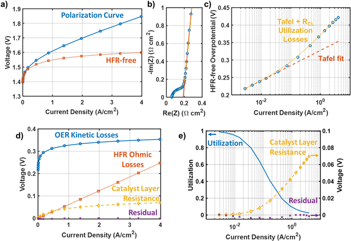
Figure 4. Analysis of catalyst layer resistance and voltage loss breakdown for a cell with Ir-NSTF anode catalyst. (a) Polarization curve and HFR-free polarization curve. Average HFR value was 61 mΩ cm2. (b) Transmission-line impedance curve measured at 1.25 V (blue circles), with transmission line curve fit (yellow dashed line) and linear intercept fit (orange solid line).  values measured with the transmission line fit and intercept fit were 466 mΩ cm2 and 382 mΩ cm2, respectively. (c) Tafel plot of the HFR-free anode overpotential (blue circles), assuming a thermodynamic voltage
  with Tafel fit (orange dashed line,
  mV decade−1,
  nA cm−2) and
  losses (yellow dotted line) plotted for comparison. The observed mass activity is 221 A gIr
−1 at 1.45 VHFR-free. (d) Voltage loss breakdown comparing kinetic losses from Tafel fit, Ohmic losses from HFR measurements, catalyst layer resistance losses, and residual losses. (e) Plot of utilization losses associated with catalyst layer resistance, voltage losses from catalyst layer resistance, and residual voltage losses.
losses (yellow dotted line) plotted for comparison. The observed mass activity is 221 A gIr
−1 at 1.45 VHFR-free. (d) Voltage loss breakdown comparing kinetic losses from Tafel fit, Ohmic losses from HFR measurements, catalyst layer resistance losses, and residual losses. (e) Plot of utilization losses associated with catalyst layer resistance, voltage losses from catalyst layer resistance, and residual voltage losses.
Download figure:
Standard image High-resolution imageThe NSTF cell exhibited overall good performance (Fig. 4a), providing approximately 4 A cm−2 at 1.85 V with an average HFR value of 61 mΩ cm2. This cell uses a membrane that is relatively thin (92 μm) membrane with low equivalent weight (800EW) ionomer, which largely accounts for the lower HFR in comparison the other cells investigated in this work, which used Nafion N115. However, the impedance curve measured in a non-faradaic condition at 1.25 V (Fig. 4b) shows a significant high-frequency feature from catalyst layer resistance. The high-frequency region of the Nyquist plot has a more rounded shape than the classic transmission line curve, possibly due to some kind of conduction bottleneck in the catalyst layer.
21,45
The catalyst layer resistance was determined from the impedance curve using both a transmission line fit and a linear intercept fit, as shown in Fig. 4b, which yielded  values of 466 mΩ cm2 and 382 mΩ cm2, respectively. Because the curved shape results in a relatively poor transmission-line fit that overestimates
  the linear intercept fit is likely more reliable, and
  = 382 mΩ cm2 was used for subsequent calculations.
The Tafel plot shown in Fig. 4c has clear linear regions at both low and high current density, corresponding to the Tafel and semi-infinite-pore limits. Based on the Tafel fit parameters ( mV/decade,
  nA cm−2) and the measured
  the transition between the Tafel and semi-infinite-pore limits is expected at a current density of
  mA, and the catalyst layer resistance losses
  (calculated using the approximation in Eq. 11) in addition to Tafel kinetic losses closely match the observed losses.
Figure 4d incorporates this calculation into a voltage loss breakdown, separating kinetic losses determined from the Tafel fit, ohmic losses determined from the HFR, and catalyst layer resistance losses. The "residual" losses plotted are the discrepancy between the overall polarization curve and the summed thermodynamic, kinetic, ohmic, and catalyst layer resistance losses. In general, these losses may include mass transport or any other process that has not been explicitly measured. The catalyst layer resistance losses and residual losses are also plotted in Fig. 4e on a semi-log scale along with the catalyst utilization determined using Eq. 11. For this cell, catalyst layer resistance losses are a significant contribution to the overall voltage, accounting for 70 mV at 4 A cm−2, with a catalyst utilization of only 2.4%. In contrast, the residual losses are very low, within ∼3 mV of zero and less than the expected experimental error, implying that there are no measurable water/oxygen transport losses for this cell under these conditions.
H2NEW IrO2 electrode
We now turn to investigation of catalyst layer resistance in the H2NEW FuGeMEA to investigate trends with electrode design parameters—namely PTL-CL interactions and catalyst layer loading/thickness. We first repeat the voltage loss breakdown analysis from previous section for a standard FuGeMEA cell (Fig. 5) to demonstrate the methods and identify differences between the systems.

Figure 5. Analysis of catalyst layer resistance and voltage loss breakdown for a FuGeMEA cell with an IrO2 anode catalyst. (a) Polarization curve and HFR-free polarization curve. Average HFR value was 112 mΩ cm2. (b) Transmission-line impedance curve measured at 1.25 V (blue circles), with transmission line curve fit (yellow dashed line) and linear intercept fit (orange solid line).  values measured with the transmission line fit and intercept fit were 28 mΩ cm2 and 19 mΩ cm2, respectively. (c) Tafel plot of the HFR-free anode overpotential (blue circles), assuming a thermodynamic voltage
  with Tafel fit (orange dashed line,
  mV/decade,
  nA/cm2) and
  losses (yellow dotted line) plotted for comparison. The observed mass activity is 149 A gIr
−1 at 1.45 VHFR-free. (d) Voltage loss breakdown comparing kinetic losses from Tafel fit, Ohmic losses from HFR measurements, catalyst layer resistance losses, and residual losses. (e) Plot of utilization losses associated with catalyst layer resistance, voltage losses from catalyst layer resistance, and residual voltage losses.
losses (yellow dotted line) plotted for comparison. The observed mass activity is 149 A gIr
−1 at 1.45 VHFR-free. (d) Voltage loss breakdown comparing kinetic losses from Tafel fit, Ohmic losses from HFR measurements, catalyst layer resistance losses, and residual losses. (e) Plot of utilization losses associated with catalyst layer resistance, voltage losses from catalyst layer resistance, and residual voltage losses.
Download figure:
Standard image High-resolution imageFigure 5a shows the overall and HFR-free polarization curves for the FuGeMEA cell, which achieves a current density of 3.8 A cm−2 at 2.0 V with an average HFR of 112 mΩ cm2. The non-Faradaic impedance curve (Fig. 5b) shows a much smaller catalyst layer resistance, compared to the Ir-NSTF cell, with a shape closely matching a classic transmission line.  values measured with the transmission line fit and intercept fit were 28 mΩ cm2 and 19 mΩ cm2, respectively. The linear intercept fit may somewhat underestimate the true value due to the inductive impedance and relatively small
  Because the transmission-line curve fits the data well and accounts for the inductive impedance, it is likely more reliable, and
  = 28 mΩ cm2 was used for subsequent calculations. As shown in Fig. 5c, the onset of additional losses above Tafel fit (
 mV/decade,
  nA cm−2) is consistent with the measured catalyst layer resistance, (which indicates
  1.5 A cm−2,) although the overall HFR-free voltage at high current density is higher than expected from Tafel kinetics and
  alone.
In the voltage loss breakdown shown in Figs. 5d–5e, the catalyst layer resistance losses are relatively smaller (∼25 mV at 4 A cm−2) compared to the previous example, as expected from the lower  However, it is important to note that
  does not decrease linearly with
  Still, catalyst layer resistance leads to a utilization of only 30% at 4 A cm−2, indicating that the overpotential and local current density vary significantly across the catalyst layer even with relatively small losses from
  This can lead to uneven catalyst degradation, as will be discussed in a later section. In this case there is also a significant residual voltage loss around 10 mV at 4 A cm−2, in contrast to the previous example, which may be caused by water or oxygen transport and will be discussed in a later section.
Both examples show slightly negative (∼2–3 mV) residual losses at intermediate potentials, which is possibly an artifact resulting from CLR leading to a slightly over-estimated Tafel slope. This artifact may be correctible by using the Ohmic approximation of CLR losses (Eq. 10) as a correction in addition to the HFR before Tafel fitting. In general, the accuracy of the  calculation appears to be highly sensitive to the quality of the Tafel fit. Investigation of methods to improve the accuracy and robustness of Tafel analysis for PEMWE cells are therefore of interest to ensure accurate voltage loss analysis.
PTL-CL interactions
The impedance and performance impacts of catalyst layer resistance are not a property of the catalyst layer alone if significant electronic resistance is present. The PTL contact to the catalyst layer will determine the distribution of current within catalyst layer and subsequent ohmic drops and utilization losses.
A series of three PTLs with different porosity was used to investigate these effects: a sintered PTL with relatively low porosity (43%) and two fiber PTLs with moderate and high porosity (59% and 74%). Visible light microscope images of these three PTLs are shown in Fig. 6a. These images were taken with the top surface of the PTLs in focus, so that the recessed pore areas of the PTL appear blurred. As visible in these images, a primary difference between the three PTLs is that the distance between the points at which the PTL will contact the catalyst layer increases significantly with the PTL porosity. This is expected to increase the path length for in-plane electronic conduction to reach the regions of the catalyst layer farthest from the catalyst layer. In principle, PTL porosity and distance between contact points are distinct variables. For a given PTL porosity, the size of the titanium particles of fibers correlates with the distance between contact points. However, the three selected PTLs all have similar particle/fiber sizes around 20 μm, and the porosity is therefore a good proxy for the in-plane conduction path length.
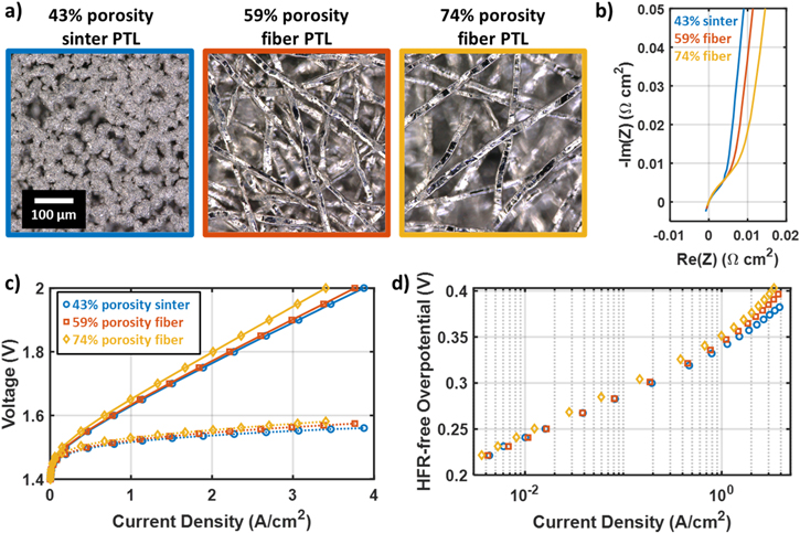
Figure 6. Analysis of catalyst layer resistance and PTL-catalyst layer interactions for FuGeMEA cells with an IrO2 anode catalyst and different PTLs. (a) Visible light microscope images of the three PTLs used to examine PTL-catalyst layer interactions influencing catalyst layer resistance effects. All images are at the same scale and focused on the top surface, so out of focus regions are recessed pore areas. (b) Non-faradaic impedance curves for FuGeMEA cells with the different PTLs. (c) Polarization curves (solid) and HFR-free voltage (dotted) for cells tested with the three different PTL types. (d) Tafel plots for cells tested with the three different PTL types.
Download figure:
Standard image High-resolution imageThe three PTLs were assembled with FuGeMEA CCMs with IrO2 anode catalyst layers at a loading of 0.34 mgIr cm−2, with an expected thickness of about 3–4 μm. Figure 6b shows that this increase in conductive path length leads to a clear increase in the catalyst layer resistance for cells having higher porosity PTLs. Quantitative values for the HFR and  are also summarized in Table I.
  increases strongly with porosity, nearly doubling from the lowest to highest porosity PTL. The HFR appears to also increase somewhat with the PTL porosity, which is expected given the lower interfacial contact area, although the trend is less clear and other factors may play a role in this result as well. For instance, all PTLs tested here have PGM coatings applied by the supplier and some difference in interfacial resistance may be expected depending on the coating methods of the different manufacturers.
Table I. Properties of PTLs used to investigate PTL/catalyst layer interactions and catalyst layer resistance for IrO2 anodes.
| Sample | Sintered PTL | 59% porosity fiber PTL | 74% porosity fiber PTL |
|---|---|---|---|
| Porosity (by weight) | 43% | 59% | 74% |
| HFR (mOhm cm2) | 111 | 109 | 118 |
 (mOhm cm2) (mOhm cm2) | 20 | 26 | 36 |
| Mass Activity (A/gIr at 1.45 VHFR-free) | 148 | 149 | 103 |
The clear increase in  with the distance between contact points implies that in-plane electronic resistance is the dominant form of catalyst layer resistance for this catalyst layer. If either through-plane ionic resistance or through-plane electronic resistance were dominant, the measured
  would not be expected to depend on the PTL contact geometry. This result is likely to apply for other catalyst layers with low loadings (≲0.5 mgIr cm−2) of unsupported IrOx catalysts, as the catalyst layer thickness (a few micrometers) is much less than the typical spacing between PTL contact points (10s to 100s of micrometers). Notably, the addition of a microporous layer to the anode PTL, which has finer features and shorter spacing between contact points compared to a conventional PTL, has been shown to improve high current density performance.
52
Catalyst composition and morphology as well as ionomer type and content are all variables that may alter the catalyst layer conductivity and present opportunities for optimization.
would not be expected to depend on the PTL contact geometry. This result is likely to apply for other catalyst layers with low loadings (≲0.5 mgIr cm−2) of unsupported IrOx catalysts, as the catalyst layer thickness (a few micrometers) is much less than the typical spacing between PTL contact points (10s to 100s of micrometers). Notably, the addition of a microporous layer to the anode PTL, which has finer features and shorter spacing between contact points compared to a conventional PTL, has been shown to improve high current density performance.
52
Catalyst composition and morphology as well as ionomer type and content are all variables that may alter the catalyst layer conductivity and present opportunities for optimization.
These findings are consistent with the results of Mandal et al.,
9
whose ex-situ measurements found that IrOx catalyst layers with ionomer content similar to that used here (I/C  0.27) had through-plane protonic conductivities that were at least an order of magnitude larger than their electronic conductivity. This supports the conclusion that electronic conductivity, rather than protonic conductivity, is limiting for IrOx catalyst layers in PEMWE. This effect would be expected to be exacerbated by the geometry of conduction in thin catalyst layers combined with the much larger-scale features of Ti-based PTLs. Furthermore, as shown by Mandal et al.
9
and Schuler et al.,
12
the electronic conductivity of the catalyst layer is significantly decreased by high humidity and especially liquid water, which lead to ionomer swelling and decreased contact between the catalyst particles. This is an important consideration as PEMWE generally has liquid water present in the anode catalyst layer and may especially decrease the electronic conductivity in regions of PTL pore, where the PTL does not effectively compress the catalyst layer to maintain internal electrical conductivity. It is important to note that the dominance of electronic resistance in IrOx catalyst layers is a key difference in comparison to PEM fuel cells, where it is generally assumed that only protonic resistance is significant in the cathode catalyst layer.
21,28–31
A number of PEMWE papers considering catalyst layer resistance have similarly assumed that only protonic resistance is significant,
10,14,15,18,19
although this does not appear to be a safe assumption for PEMWE generally.
0.27) had through-plane protonic conductivities that were at least an order of magnitude larger than their electronic conductivity. This supports the conclusion that electronic conductivity, rather than protonic conductivity, is limiting for IrOx catalyst layers in PEMWE. This effect would be expected to be exacerbated by the geometry of conduction in thin catalyst layers combined with the much larger-scale features of Ti-based PTLs. Furthermore, as shown by Mandal et al.
9
and Schuler et al.,
12
the electronic conductivity of the catalyst layer is significantly decreased by high humidity and especially liquid water, which lead to ionomer swelling and decreased contact between the catalyst particles. This is an important consideration as PEMWE generally has liquid water present in the anode catalyst layer and may especially decrease the electronic conductivity in regions of PTL pore, where the PTL does not effectively compress the catalyst layer to maintain internal electrical conductivity. It is important to note that the dominance of electronic resistance in IrOx catalyst layers is a key difference in comparison to PEM fuel cells, where it is generally assumed that only protonic resistance is significant in the cathode catalyst layer.
21,28–31
A number of PEMWE papers considering catalyst layer resistance have similarly assumed that only protonic resistance is significant,
10,14,15,18,19
although this does not appear to be a safe assumption for PEMWE generally.
The performance impacts of the PTL/catalyst layer interaction are shown in Figs. 6c–6d. The polarization curves and HFR-free voltage (Fig. 6c) are both worse for the higher porosity PTLs, as expected from the trends in HFR and  Tafel plots for these cells (Fig. 6d) show that the HFR-free voltage varies most at high current densities, as expected from the trend in
  with relative convergence in the Tafel regime at low current density. The 59% porosity fiber PTL and the 43% porosity sinter PTL both have very similar low current density performance, with almost identical mass activity measured at 1.45 VHFR-free (Table I). However, the 74% porosity fiber PTL shows a somewhat worse low-current density performance and a 30% lower mass activity, suggesting that the high porosity of the PTL may lead to some fragmentation of the catalyst layer that leaves some catalyst electronically isolated and inactive. We observe an increase in HFR with current density for all samples, with the magnitude of the increase correlating to
  (Fig. S3). This is most likely a result of decreasing catalyst utilization causing more ionic current to pass through certain regions of the membrane, effectively lowering the membrane utilization at high current.
Trend of CLR with catalyst layer loading
A series of electrodes were prepared with different loadings from 0.12 mgIr cm−2 to 0.34 mgIr cm−2 to investigate the impact of catalyst layer loading and thickness on catalyst layer resistance effects in FuGeMEA-type cells. Because catalyst layer resistance is likely sensitive to electrode properties such as ionomer content and the fabrication process, special care was taken to ensure that catalyst layers were otherwise as similar as possible. The catalyst ink for all samples was prepared together and coated on the same day, with each batch being same size and mixed shortly before spray coating.
The performance and impedance of these samples is compared and analyzed in Fig. 7, with numerical values reported in Table II. Figure 7a shows polarization curves for the three different loadings, and a modest trend is visible toward higher performance with higher loading. The three cells all had nearly identical HFR (109–111 mΩ cm2), and so the performance differences are generally from the HFR-free voltage. At low current density, the variation is roughly as expected based on Tafel kinetics and the change in loading, as the loading-corrected Tafel plots (supplemental Fig. S1(a)) are very nearly overlapping (within ∼5 mV), although with slightly higher HFR-free voltage for lower loadings in the Tafel regime. This implies roughly consistent utilization of the catalyst layer at low current density, although possibly with some loss of utilization at lower loadings as the catalyst layer may lose electrical continuity in the thin, low loaded catalyst layers. This trend is apparent in the mass activity measured at 1.45 VHFR-free (Table II), which is similar for all three loadings, although with a trend of increasing mass activity at higher loading. This is most likely for the same reason noted in the previous section, as thinner catalyst layers may be prone to fragmentation that electronically isolates some catalyst, leaving it inactive and lowering the effective mass activity. This trend is further shown in Fig. S1(c) for all the catalyst layers and loadings tested, which shows that either lower catalyst loadings or higher porosity PTLs can lead to a loss of effective mass activity.

Figure 7. Investigation of trends in performance and catalyst layer resistance with IrO2 anode catalyst loading for FuGeMEA-type cells. (a) Comparison of polarization curves and HFR-free voltage for loadings from 0.12 mgIr cm−2 to 0.34 mgIr cm−2. All subfigures follow the same color labels as (a). (b) Transmission-line impedance curves for the three different loadings. (c) Tafel plots for the different loadings, with superimposed Tafel fits (dashed lines) and calculated catalyst layer resistance losses (dotted lines). (d) Catalyst layer resistance losses (solid lines) and residual voltage (symbols) for the three samples.
Download figure:
Standard image High-resolution imageTable II. Comparison of performance, impedance, and kinetic properties for FuGeMEA cells with different loadings.
| Anode loading (mgIr/cm2) | 0.12 | 0.22 | 0.34 |
|---|---|---|---|
| HFR (mΩ cm2) | 109 | 111 | 111 |
 (mΩ cm2) (mΩ cm2) | 39 | 32 | 25 |
| "Flat" capacitance fraction (%) | 19 | 17 | 7 |
Tafel slope  (mV/dec) (mV/dec) | 49 | 48 | 49 |
Exchange current density  (nA/cm2) (nA/cm2) | 35 | 53 | 130 |
| Mass Activity (A/gIr at 1.45 VHFR-free) | 112 | 130 | 149 |
The non-faradaic impedance curves in Fig. 7b show a notable shape change with loading. While the 0.34 mgIr m−2 sample generally follows a classic transmission-line shape as noted above, at lower loadings the curve is shifted up at higher frequencies and tipped to a lower angle at low frequencies, both likely indicating increasing heterogeneity in the catalyst layer. In particular, for very thin catalyst layers it is expected that regions of the catalyst layer directly adjacent to areas with PTL contact will experience a much lower electronic resistance than regions far from a PTL contact. This growing differentiation between regions near and far from PTL contacts at lower loading likely explains the observed trend. An analogous model present in the literature is a porous electrode with a flat surface region facing the electrolyte, having some share of the total capacitance but no transmission-line type resistance. In this case, the "flat" region represents a portion of the electrode with negligible resistance.
22
This type of electrode has the same characteristic upward shift at high frequency visible in Fig. 7b. Adding a flat segment to the transmission line fit results in a good fit for all the different loadings (supplemental Fig. S1(b)). The relevant fit parameters are summarized in Table II. These fits show a moderate increase in  at low loading, from 25 mΩ cm2 for 0.34 mgIr cm−2 to 39 mΩ cm2 for 0.12 mgIr cm−2. These resistances are comparable in magnitude to those measured by Babic et al., although they assumed that the catalyst layer resistance was entirely due to protonic resistance.
14,19
at low loading, from 25 mΩ cm2 for 0.34 mgIr cm−2 to 39 mΩ cm2 for 0.12 mgIr cm−2. These resistances are comparable in magnitude to those measured by Babic et al., although they assumed that the catalyst layer resistance was entirely due to protonic resistance.
14,19
Assuming linear conduction away from straight PTL fibers, the expected trend for pure in-plane resistance would be for  to vary inversely with loading while for pure through-plane resistance
  would be proportional to the loading. The observed trend, being weaker than inverse proportionality but still decreasing with loading, implies that for these catalyst layers the resistance is primarily, but not entirely, in-plane.
Figures 7c–7d shows the calculated catalyst layer resistance losses  in comparison to the overall HFR-free voltage. The increase in
  at lower loadings leads to a modest increase in
  by about 6–7 mV at high current density from the highest to the lowest loading samples. A larger change is visible in the residual losses after accounting for
  which increase roughly three-fold at low loading to become nearly as large as
  at 0.12 mgIr cm−2. While we cannot conclusively attribute these without further measurement, it is possible that these are water/oxygen transport losses. If so, it is notable that the trend is inverse with the catalyst layer thickness, which would rule out through-plane diffusion across either the PTL or the catalyst layer as the cause. Instead, it is possible that with thinner catalyst layers there is an in-plane transport limitation under the PTL contact regions, which are sustaining very high local current density because of the in-plane catalyst layer resistance. This could be expected to have similar mathematical behavior to catalyst layer resistance, further shrinking the utilized catalyst layer to near the edge of the PTL contact. It is also possible that the complex geometry of this electrode could create unanticipated catalyst layer resistance effects, such as in-plane electronic resistance combined with through-plane ionic resistance. Fully understanding the charge and mass transport effects in this system will take further study.
Durability impacts—Uneven catalyst layer degradation resulting from catalyst layer resistance
In general, catalyst layer resistance leads to decreasing catalyst utilization at high current density, with some regions being more highly utilized and exposed to larger overpotentials than others. This heterogeneous distribution of overpotential is expected to lead to spatially varying degradation of the catalyst layer over time, which depends on the dominant type of resistance present.
A durability tested FuGeMEA CCM was analyzed post-mortem in cross-section using scanning transmission electron microscopy (STEM) to investigate this effect (Fig. 8). A relatively low anode catalyst loading of 0.16 mgIr cm−2 was used to provide increased sensitivity to catalyst layer degradation. 7 The durability test consisted of 500 h of a square wave cycle from 1.4 V to 2.0 V, with one cycle per minute. Polarization curves were recorded every 5000 cycles during the test, and impedance diagnostics were recorded before (BOT) and after the test (EOT).

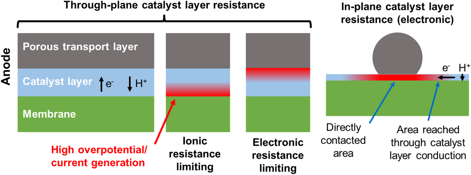
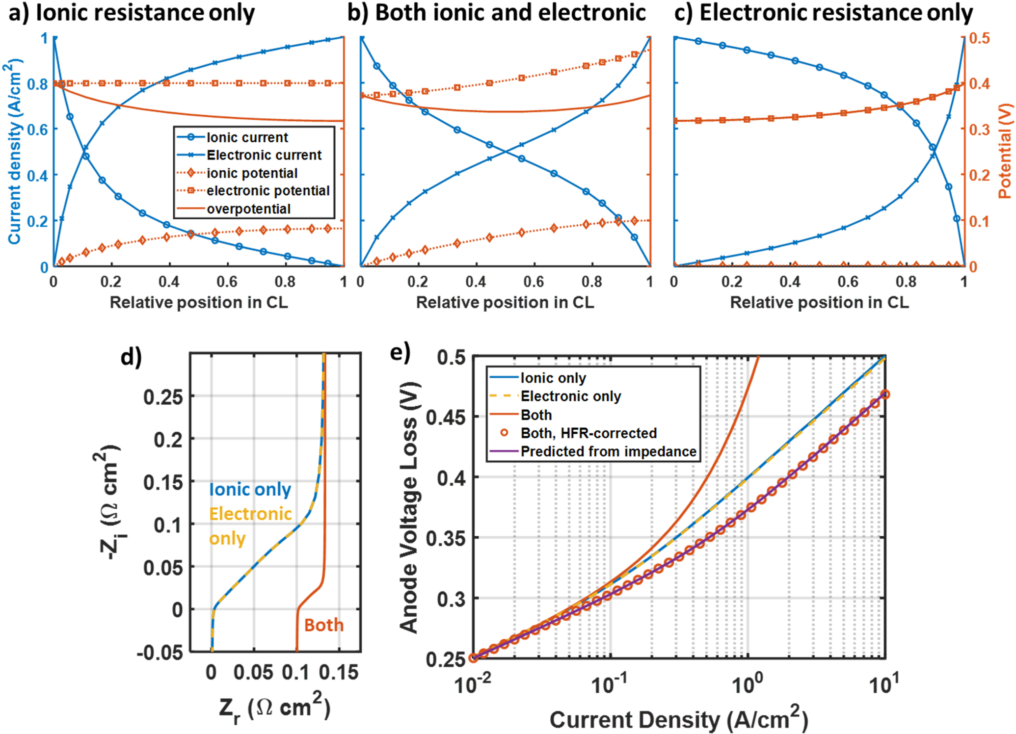
Figure 8. Investigation of degradation impacts of catalyst layer resistance for a FuFeMEA cell with IrO2 catalyst at a 0.16 mgIr cm−2 loading and 59% porosity fiber PTL. (a) Polarization curves taken before (BOT), after (EOT) and during a 1.4–2.0 V square-wave cycle durability test. (b) Comparison of total (solid) and HFR-free (dashed) polarization curves before and after the durability test. The average HFR fell slightly from 106 mΩ cm2 at BOT to 105 mΩ cm2 at EOT. (c) Transmission-line impedance curves before and after the durability test, with intercept fits shown by solid lines. RCL was found to be 42 mΩ cm2 before and 44 mΩ cm2 after the test, respectively. (d) Tafel plots before and after the durability test, with Tafel fits shown by solid lines and losses from catalyst layer resistance and Tafel kinetics shown by dotted lines. (e) Post-mortem, cross-sectional STEM images of the anode catalyst layer at EOT showing uneven degradation.
Download figure:
Standard image High-resolution image
The overall change in performance is shown by the change in polarization curves across the durability test in Fig. 8. A relatively steady rate of degradation was observed across the test, with the voltage at 4 A cm−2 increasing by about 53 mV, and the current density at 2 V falling by about 12%. The cell HFR was roughly the same or slightly lower after the durability test, with 106 mΩ cm2 at BOT and 105 mΩ cm2 at EOT. Thus, the performance losses are entirely in the HFR-free voltage, as shown in Figs. 8b, 8d, including an increase of about 25 mV in the Tafel regime and a larger increase at higher current densities (40 mV at 0.8 A cm−2). (Impedance diagnostics above 0.8 A cm−2 were not available for this test.) These losses indicate degradation of the anode catalyst layer as the primary change impacting cell performance. Transmission-line impedance curves are shown in Fig. 8c. A very small change in these impedance curves is visible from BOT to EOT and the  was found to be 42 mΩ cm2 at BOT and 44 mΩ cm2 at EOT. Therefore, it does not appear that the catalyst layer resistance changed significantly during the durability test. The Tafel plots in Fig. 8d show the voltage losses resulting from these
  values. For the BOT Tafel plot, the CLR losses and Tafel kinetics appear to account for essentially all of the HFR-free voltage observed at currents up to 0.8 A cm−2. However, the additional HFR-free voltage losses observed for EOT are not accounted for and may come from a different mechanism.
While the voltage losses from CLR shown in Fig. 8d are relatively small, the measured  implies a significant impact on the catalyst utilization at high current densities. During the durability test when the upper voltage of 2.0 V is applied, the current density ranged from approximately 3.9 A cm−2 at BOT to 3.4 A cm−2 at EOT. Based on the measured
  and Eq. 11, the catalyst utilization at 2 V during the durability test therefore ranged from 21% (BOT) to 25% (EOT). Therefore, less than a quarter of the catalyst is expected to experience the full overpotential applied by the test, which leads to spatially uneven degradation in the catalyst layer.
The post-mortem STEM images (Fig. 8e) of the anode catalyst layer in CCM cross-sections after the durability test show that the degradation was highly uneven in-plane. Some regions of the catalyst layer have a significant band of iridium formed in the adjacent membrane from dissolved and re-deposited catalyst, while other regions appear nearly pristine with no iridium band. STEM EDS measurements (Fig. S2) show that the iridium band is composed of iridium oxide. Notably, the degraded regions with an iridium band all appear to be in locations where the catalyst layer has been indented into the membrane, presumably by the anode PTL. It thus appears that degradation is significantly faster in regions directly contacted by the PTL in comparison to regions adjacent to PTL pores. This is the expected pattern of degradation for a catalyst layer with dominant in-plane electronic resistance, as conduction in-plane in the catalyst layer away from regions of PTL contact will lead to ohmic drops that decrease the applied overpotential at the catalyst surface. This is consistent with the evidence presented in the previous two sections that in-plane electronic resistance is dominant in low-loaded IrO2 catalyst layers.
This result also highlights that catalyst layer resistance can be an important risk factor for electrolyzer durability, especially for low Ir-loaded anodes. Regions of the catalyst layer that contact the PTL are critical for providing conduction to the rest of the catalyst layer. However, when significant in-plane electronic resistance is present, these regions are the most active at high current density and will degrade fastest and fail first, potentially disconnecting un-damaged parts of the catalyst layer. While we did not observe a significant increase in  from the durability test, this effect may be responsible for the faster degradation in the HFR-free voltage at higher current densities (Fig. 8c) because the catalyst layer regions that are most utilized at high current densities have experienced the most degradation. Further investigations of the durability impacts of catalyst layer/PTL interactions are ongoing.
Conclusions
This paper presented methods for making in-situ, impedance-based measurements of anode catalyst layer resistance in PEM electrolysis cells and quantifying the resulting utilization and voltage losses. New, simple approximations were presented for calculation of voltage losses due to catalyst layer resistance to facilitate routine inclusion in voltage loss breakdown analysis. We employed these methods to investigate the effects of catalyst layer resistance on cell performance and durability.
The methods were demonstrated for cells with two different anode catalyst systems: dispersed Ir-NSTF and IrO2. In-depth investigation of catalyst layer resistance effects in the H2NEW FuGeMEA cell (IrO2 anode) was presented, including trends with anode catalyst loading and PTL-catalyst layer interactions. These results indicate that in-plane electronic resistance is the primary form of resistance in the low-loaded IrO2 catalyst layers investigated. This leads to a concentration of oxygen evolution current and high local overpotentials in the anode around areas of contact between the PTL and catalyst layer. We observed accelerated degradation in these regions of the catalyst layer that contact the PTL directly, which may lead to early failure of the anode. These results likely apply to other similar electrolysis cells with low-loaded IrO2 catalyst layers and currently available PTLs because of the large discrepancy between the catalyst layer thickness (few μm) and the spacing between PTL contact areas (10's to 100's of μm).
The in-plane electronic conductivity limitation can be addressed by either improving the intrinsic conductivity of the catalyst layer or spreading out contact to the PTL, such as with a microporous layer. Such improvements to electrolyzer anodes that decrease the effective catalyst layer resistance should be advantageous for both efficiency and lifetime and are therefore likely fruitful areas for future research. The methods presented in this manuscript can guide these improvements by enabling routine characterization of catalyst layer resistance effects in any lab using impedance diagnostics for PEM electrolyzer cell testing. The authors recommend these methods be adopted routinely for PEMWE characterization and voltage loss breakdown analysis. While the approach presented here does not necessarily cover the full complexity present in heterogeneous, dynamic anode catalyst layers, it provides a first-order measurement of catalyst layer resistance effects to inform deeper understanding of electrolyzer anodes.
Acknowledgments
This work was authored by the National Renewable Energy Laboratory, operated by Alliance for Sustainable Energy, LLC, for the U.S. Department of Energy (DOE) under Contract No. DE-AC36–08GO28308. Funding provided by U.S. Department of Energy Office of Energy Efficiency and Renewable Energy, Hydrogen and Fuel Cell Technologies Office through award DE-EE0009237 and the H2NEW consortium. The views expressed in the article do not necessarily represent the views of the DOE or the U.S. Government. The U.S. Government retains and the publisher, by accepting the article for publication, acknowledges that the U.S. Government retains a nonexclusive, paid-up, irrevocable, worldwide license to publish or reproduce the published form of this work, or allow others to do so, for U.S. Government purposes. The authors thank Timothy Van Cleve, KC Neyerlin, Prantik Saha, Bryan Pivovar, Tobias Schuler, Jacob Wrubel, Robin Rice, and Megan Holtz for useful conversations, and Ellis Klein and Christian Milleville for testing and facility support. The Talos F200X was provided by US DOE, Office of Nuclear Energy, Fuel Cycle R&D Program and the Nuclear Science User Facilities.
Supplementary information (0.7 MB PDF)
Supplementary calculator (0.1 MB XLSX)