Abstract
All-solid-state lithium-sulfur batteries (ASSLSBs) offer a means to enhance the energy density and safety of the state-of-art lithium-ion batteries (LIBs), due to their high gravimetric energy density, low cost and environmental benignancy. In this work, the status of the research advances and perspectives on several types of solid electrolytes (SEs) developed for ASSLSBs are reviewed. The promises and challenges of utilizing SEs are discussed taking into account both theoretical calculation and experimental results, in hope of shedding some lights on future design of high energy density, cost competitive, and safe Li-S batteries.
Export citation and abstract BibTeX RIS

This is an open access article distributed under the terms of the Creative Commons Attribution Non-Commercial No Derivatives 4.0 License (CC BY-NC-ND, http://creativecommons.org/licenses/by-nc-nd/4.0/), which permits non-commercial reuse, distribution, and reproduction in any medium, provided the original work is not changed in any way and is properly cited. For permission for commercial reuse, please email: oa@electrochem.org.
Lithium-sulfur (Li-S) batteries have been extensively investigated for lightweight applications (e.g., aircraft, artificial satellite, and unmanned aerial vehicles), and large-scale stationary energy storage, owing to their high gravimetric energy density, low cost, and environmental friendliness.1–3 The deployment of Li-S batteries into commercial market is hampered by several seemingly intrinsic problems resulting from the complex cell chemistry. Firstly, the electronically insulating nature of elemental sulfur (S8) and end-product lithium sulfide (Li2S) leads to unstable electrochemical contact within S cathode.4–7 Secondly, the soluble intermediates of polysulfide (PS) can diffuse between the cathode and anode (i.e., shuttle effect of PS), generating an active material loss in S cathode and degrading metallic Li anode.4–9 Thirdly, the formation of 'dead' Li and Li dendrites upon cycling could not only decrease the Coulombic efficiency but also raise safety issues.10–12
In recent years, various strategies have been attempted to overcome the above-mentioned problems. Most of the efforts have been devoted to enhance the electrochemical performance of Li-S batteries using well-designed cathode materials.13 The diffusion of polysulfide species generated during discharge into electrolytes can be significantly suppressed by infusing sulfur into carbon materials in the cathode with an adequately controlled and engineered porosity and pore size, thus increasing the practical capacity and cyclability of Li-S batteries. These rational and creative strategies of cathode design have been covered by a number of recent reviews.7,14,15 Besides, new binders (e.g., poly(ethylene oxide) (PEO)16 and carboxymethycellulose (CMC)17,18) have been employed for guarantying the integrity of the morphology and structure of S cathode, and enhancing the adhesion to current collector. The modification of separators (e.g., multiwall carbon nanotubes coated polypropylene19 and lithiated Nafion20) have been also developed for reducing the migration of polysulfides, thus mitigating the shuttle effect of PS.21
Apart from the strategies mentioned above, another approach, focusing on electrolyte formulation and modification, has been proved to be effective. The performances of Li-S batteries are largely affected by the electrolyte recipes, such as the type and identity of solvents, nature of Li-salts and their concentrations and functional additives.22 To date, liquid solutions of lithium bis(trifluoromethanesulfonyl)imide ([(CF3SO2)2N]Li, LiTFSI) in a mixture of linear (e.g., 1,2-dimethoxyethane (DME)) and cyclic ethers (e.g., 1,3-dioxolane (DOL)) solvents containing small amount of lithium nitrate (LiNO3) as an additive are used as archetypal electrolytes. This is mainly motivated by several intrinsic features of the electrolyte components, including (1) the highly delocalized negative charge distribution of TFSI−, being crucial for effectively reducing the interactions between Li+ and TFSI− and thereby increasing the dissociation and solubility of LiTFSI in ether solvents, thus leading to the enhancement of ionic conductivity at room temperature;23,24 (2) the capability of DOL in forming insoluble and flexible surface films (also called solid electrolyte interphase, SEI) of dioxolane oligomer (–(OCH2CH2OCH2)n–), which serve as a means to prevent dendrite formation, accommodate morphology/volume changes of the electrodes while allowing highly facile Li-ion transport. This ultimately results in improving the cycling life and efficiency of Li-S batteries;25 (3) the participation of LiNO3 in formation of SEI on the surface of Li metal anode leading to enhanced the stability of Li anode and suppressed the redox shuttle effect of polysulfides and self-discharge, thus improving the cycling performances of Li-S batteries.26–29 Besides to form a robust passivation layer, LiNO3 has also recently reported to catalyze the conversion of highly soluble polysulfide to slightly soluble S8, providing a synergetic improvement to Li-S batteries.30 Another strategy consists in the design of the so-called "sparingly solvating" electrolytes in which the di-charged polysulfides are insoluble while the main salt, i.e. LiTFSI is still soluble.31,32 However, the conductivity is one order of magnitude lower than that of DME/DOL-electrolytes.
Despite the above advantages of liquid electrolytes, in effective, organic solvents, may be with the exception of those sufficiently fluorinated and that of ionic liquids, are highly flammable and cause safety concerns. Hence, solid-state Li-ion conductors, encompassing inorganic electrolytes and organic polymer electrolytes (PEs), have emerged as promising alternatives to these conventional liquid electrolytes, possibly enabling the development of safe rechargeable Li-S batteries.33,34 Several comprehensive reviews of electrolytes for Li–S batteries have been published recently; however, little attention has been paid to solid electrolytes for all-solid-state Li-S batteries (ASSLSBs).14,22,35,36 This work presents an overview of the current status and state-of-art enlisting both inorganic and PEs, which have been implemented in ASSLSBs. On the basis of the energy density calculation making use of various electrolytes, the existing opportunities, challenges and future work on enabling solid electrolytes as the key path toward long-term and high energy density Li-S batteries are extensively discussed.
Current Status
Since the first study on poly(ethylene oxide) (PEO) -based electrolyte for Li-S cells in the late of 1980s by DeGott,37 several types of solid electrolytes have been investigated as Li-ion conducting materials for ASSLSBs, including those based on pure polymeric components,38–49 ceramic electrolytes,50–67 and composite electrolytes (mix of ceramic and other electrolytes).68–70 Generally, PEs can be classified into two categories: solid polymer electrolytes (SPEs) and gel polymer electrolytes (GPEs). In the former electrolyte system, lithium salts are dissolved in high-molecular-weight polymers containing high concentration of Lewis base groups such as ether (–O–), carbonyl (–C=O), and cyano (–C≡N), which serve as ligands for coordinating Li+ of the dissolved salt thus offering the necessary solvation energy for the polymer-lithium complex formation. In GPEs, low molecular weight components like small organic solvent (e.g., tetra(ethylene glycol) dimethyl ether,39,71 DOL,72 carbonates73–78), and ionic liquids79,80 are added as plasticizers for improving the ionic conductivity of a polymer electrolyte. The chemical structures of the extensively studied lithium salt, polymer matrices, and low molecular weight plasticizers are summarized in Fig. 1. Another important class of solid electrolytes, the inorganic solid electrolytes, exhibit higher Li-ion conductivities at operating temperature (e.g., 10−2 S cm−1 at 25 °C for Li10GeP2S1281) compared to SPEs; while SPEs have better processability and in principle are easier to be scaled up for large-format batteries, as demonstrated by the application of Bluecar from Blue Solutions in several cities (e.g., Paris, Bordeaux, Lyon, Indianapolis, etc.), which are equipped with a 30 kWh LiFePO4/PEs/Li-metal battery pack, providing a 250 km driving range under normal urban use.82

Figure 1. The chemical structures of the extensively studied lithium salt, polymer matrices, and plasticizers for solid electrolytes.
Looking at the existing literature related to ASSLSBs, the cyclability and S utilization of the cells are important parameters for comparing the overall performances. The detailed information of ASSLSBs from literature is listed in Table I, in terms of the composition of the electrodes (cathode and anode), electrolyte formulation and conductivity of the electrolyte.
Table I. State of art of Li-S cell with various types of electrolytes from literature.a
| Cathode | Electrolyte | Cycle performance | |||||||
|---|---|---|---|---|---|---|---|---|---|
| Composition / wt% | S content / wt% | Anode | Composition | Ionic conductivity / mS cm−1 | Capacity / mAh g−1; material considered | T /°C | C-rate | Voltage window / V | Ref |
| Ceramic electrolyte | |||||||||
| S (25) / AB (25) / SE (50) | 25 | Li/In | 80Li2S-20P2S5 | 5 (25°C) | 1200 (1st) vs. 996 (200th); S | 25 | 0.14 mA cm−2 | 0.7−2.7 | 56 |
| S/Cu (38) / AB (5) / SE (57) | 23 | Li | 80Li2S-20P2S5 | 5 (25°C) | 660 (1st) vs. 650 (20th); CuS | 25 | 0.064 mA cm−2 | 0.3−2.7 | 50,51 |
| Li2S/Cu (38) / AB (5) / SE (57) | 18 | In | 80Li2S-20P2S5 | 5 (25°C) | 500 (1st) vs. 340 (20th); Cu-Li2S | 25 | 0.064 mA cm−2 | 0.3−2.7 | 53 |
| Li3PS4+5 (60) / carbon (30) / PVC (10) | 28 | Li/Ni | Li3PS4 | 0.1 (60°C) | 1400 (1st) vs. 1200 (300th); S | 60 | 0.015 mA cm−2 | 1.5−2.8 | 60 |
| Li2S (25) /AB (25) / SE (50) | 18 | In | 80Li2S-20P2S5 | 5 (25°C) | 650 (1st) vs. 650 (10th); Li2S | 25 | 0.064 mA cm−2 | 0.3−2.7 | 58 |
| S (35) / AB (35) / SE (30) | 35 | Li | 80Li2S-20P2S5 | 5 (25°C) | 1000 (3rd) vs. 900 (20th); Li2S | 25 | 0.064 mA cm−2 | 0.3−2.7 | 57 |
| S (27) / Cu (21.4) / AB (1.6) / SE (50) | 27 | Li4.4Ge | 60Li2S-40SiS2 | 0.2 (25°C) | 1000 (1st) vs. 1100 (20th); S | 25 | 0.064 mA cm−2 | 0.3−2.6 | 52 |
| Li2S (15) / AB (15) / SE (70) | 27 | In | 0.01Li3PO4-0.63Li2S-0.36SiS2 | 1.5 (30°C) | 900 (1st) vs. 700 (20th); Li2S | 30 | 0.067 mA cm−2 | 0.4−3.0 | 55 |
| S (30) / CNF (10) / SE (60) | 30 | Li | 75Li2S-25P2S5 | 0.1 (30°C) | 1600 (1st) vs. 1400 (10th), S | 30 | 0.025 mA cm−2 | 1.3−2.6 | 65 |
| S (25) / AB (25) / SE (50) | 30 | Li0.61Al | Li3.25Ge0.25P0.75S4 | 2.2 (25°C) | 1500 (1st) vs. 900 (10th); S | 25 | 0.013 mA cm−2 | 0.5−2.7 | 54 |
| S (30) / VGCF (10) / SE (60) | 30 | Li4.4Si | amorphous Li3PS4 | 0.1 (25°C) | 1300 (1st) vs. 1200 (50th), S | 25 | 0.1 mA cm−2 | 0.9−2.6 | 64 |
| S (50) / KB (10) / SE (40) | 50 | Li0.79In | 60Li2S-40P2S5 | 0.02 (25°C) | 1300 (1st) vs. 1300 (50th), S | 25 | 1.3 mA cm−2 | 0.5−2.5 | 63 |
| Li2S@P2S5 (65) / carbon (25) / PVC (10) | 44 | Li/Ni | β-Li3PS4 | 1 (60°C) | 1216 (1st) vs. 852 (100th), S | 60 | 0.02 mA cm−2 | 1.5−2.8 | 61 |
| S (23) / MCMB (23) / SP (46) / SE (8) | 23 | Li | Li2S–P2S5 | 5 (80°C) | 400 (1st) vs. 400 (18th), S | 80 | 84 mA g−1. | 1−5 | 62 |
| Li2S (25) / AB (25) / SE (50) | 25 | In | 75Li2S-25P2S5 | 0.1 (25°C) | 600 (1st) vs. 600 (10th), Li2S | 80 | 0.064 mA cm−2 | 0−3 | 66 |
| S (30) / CMK-3 (20) / SE (50) | 30 | Li0.61Al | Li3.25Ge0.25P0.75S4 | 2.2 (25°C) | 1600 (1st) vs. 700 30th); S | 25 | 0.13 mA cm−2 | 0.5−2.7 | 59 |
| S (35) / AC (15) / SE (50) | 35 | Li4.4Si | 70Li2S–30P2S5 | N.A. | 300 (1st) vs. 250 (6th); S | 25 | 0.13 mA cm−2 | 0.5−2.7 | 67 |
| Solid polymer electrolytes | |||||||||
| S (50) / carbon (16) / SE (34) | 50 | Li | LiTFSI/PEO (1/49, weight) | 0.49 (90°C) | 722 (1st) vs. 270 (10th); electrode | 90 | 0.050 mA cm−2 | 1.5−2.7 | 38 |
| S (50) / AB (5) / PEO (40) / LiTf (5) | 50 | Li | PEO10LiTf + TixO2x-1 (x = 1, 2, 85/15, weight) | 0.22 (90°C) | 1650 (1st) vs. 490 (10th); S | 90 | 0.14 mA cm−2 | 1.7−3.2 | 39 |
| S/C (80) / SP (10) / PVdF (10) | 40 | Li | PEO20LiTf + 10 wt% S-ZrO2 + Li2S. | 0.1 (70°C) | 400 (1st) vs. 500 (30th); S | 70 | 30 mA g−1 | 1.5−3.2 | 42 |
| S composite (60) / AB (20) / PEO (20) | 40 | Li | PEO18LiTFSI–10 wt% SiO2 | 0.5 (70°C) | 1266 (1st) vs. 823 (25th); S | 70 | 0.1 mA cm−2 | 1−3 | 43 |
| S / AB / PEO | N. A. | Li | PEO6LiBF4–10 wt% Al2O3 | 0.3 (80°C) | 1600 (1st) vs. 40 (10th); S | 80 | 0.07 mA cm−2 | 1.7−3 | 41 |
| S (24) / AB (10) / PEO (56) / PVdF (10) | 24 | Li | P(EO)20LiTFSI–10 wt% γ-LiAlO2 | > 0.1 (75°C) | 452 (1st) vs. 184 (50th); electrode, | 75 | 0.1 mA cm−2 | 1.5−3.2 | 40 |
| CMK3-S (65) / SP (10) / SE (20) / PVdF (5) | 45 | Li | P(EO)20LiTNFSI | 0.1 (60°C) | 450 (6th) vs. 450 (200th); electrode | 60 | 0.2 C | 1.6−2.5 | 45 |
| S composite (80) / SP (10) / binder (10) | 30 | Li | P(EO)15LiTFSI + 10 wt% HNT | 0.1 (25 °C) | 800 (1st), 745 (100th); S | 25 | 0.1 C | 1.2−3.0 | 47 |
| S composite (80) / SP (10) / binder (10) | 43 | Li | P(EO)15LiTFSI + 6.5 wt% MIL-53(Al) | N.A. | 1000 (1st) vs. 558 (1000th); S | 60 | 0.5 C | 1.0−3.0 | 44 |
| S (60) / SP (30) / PAA (10) | 60 | Li | P(EO)15LiTFSI + 10 wt% MIL-53(Al) | 0.6 (80 °C) | 1450 (1st) vs. 792 (50th); S | 80 | 0.5 C | 1.5−2.8 | 46 |
| S (40) / carbon (15) / SE (45) | 40 | Li | P(EO)20LiFSI | 0.74 (70°C) | 900 (1st) vs. 600 (50th); S | 70 | 0.1 C | 1.6−2.8 | 48 |
| S (40) / carbon (15) / SE (45) | 40 | Li | P(EO)20LiFSI + 3 vol% LICGC | 0.6 (70°C) | 1000 (1st) vs. 600 (50th); S | 70 | 0.1 C | 1.6−2.8 | 49 |
| Gel polymer electrolytes | |||||||||
| Li2S (35) / SP (35) / PEO20LiTf (30) | 35 | Sn/C | PEO20LiTf + 10 wt% S-ZrO2 in EC/DMC + Li2S | 5 (25°C) | 1200 (1st) vs. 800 (30th); Li2S | 25 | 0.038 mA cm−2 | 0.2−4.0 | 74 |
| S (50) / carbon (5) / PVdF-HFP (40) / LiBF4 (5) | 50 | Li | LiBF4 + PVdF-HFP + TEGDME | 0.62 (25°C) | 1450 (1st) vs. 400 (10th); S | 25 | 0.14 mA cm−2 | 1.7−3.2 | |
| S (50) / carbon (5) / PVdF-HFP (40) / LiPF6 (5) | 50 | Li | LiPF6 + PVdF-HFP + TEGDME | 1.89 (25°C) | 1500 (1st) vs. 500 (10th); S | 25 | 0.14 mA cm−2 | 1.7−3.2 | 83 |
| S (50) / carbon (5) / PVdF-HFP (40) / LiPF6 (5) | 50 | L | LiTf + PVdF-HFP + TEGDME | 0.33 (25°C) | 1200 (1st) vs. 450 (10th); S | 25 | 0.14 mA cm−2 | 1.7−3.2 | |
| S (50) / SP (15) / PEO8LiClO4 (35) | 50 | Li | LiClO4 + PEO + TEGDME | 0.34 (25°C) | 320 (1st) vs. 160 (10th); S | 25 | 0.05 mA cm−2 | 1.7−2.7 | 71 |
| S composite (60) / AB (30) / PVdF (10) | 30 | Li | PVdF-HFP + LiTFSI + PY14TFSI | 0.25 (25°C) | 1218 (1st) vs. 818 (20th); S | 25 | 0.050 mA cm−2 | 1.0−3.0 | 80 |
| S (60) / carbon (25) / PEO (15) | 60 | Li | LiTf + PVdF + TEGDME | N.A. | 1268 (1st); S | 22 | 0.14 mA cm−2 | 1.7−3.5 | 84 |
| S (42) / carbon (28) / SP (20) / PVdF (10) | 42 | Li | Cellulose + LiTFSI + TEGDME + DOL + LiNO3 | 1.2 (20°C) | 730 (1st) vs. 730 (60th); S | 20 | 0.58 mA cm−2 | 1.5−3.0 | 72 |
| S (40) / MCMB (40) / SP (10) / PVdF (10) | 4 | LixSn-C | PEO20LiTf + 10 wt% ZrO2 in EC/DMC | 1.3 (25°C) | 600 (1st) vs. 500 (20th); S | 25 | 0.335 mA cm−2 | 0.2−3.8 | 78 |
| S (52) / GNS (28) / AB (10) / PVdF (10) | 52 | Li | PVdF-HFP/PMMA/SiO2 in LiTFSI-TEGDME | 3.1 (25°C) | 809 (1st) vs. 413 (50th); S | 25 | 0.335 mA cm−2 | 1−3 | 85 |
| S (30) / AC (40) / AB (20) / PTFE (10) | 21 | Li | PVdF-HFP/SiO2 in LiPF6-PC/EC/DEC | 1.2 (25°C) | 560 (1st) vs. 300 (25th); electrode | 25 | 0.3 mA cm−2 | 1−3 | 73 |
| S (38) / PAN (38) / Mg0.6Ni0.4O (4) / AB (10) /PVdF (10) | 38 | Li | PVdF-HFP + silicates in LiPF6-EC/DEC | 4.9 (25°C) | 900 (1st) vs. 500 (300th); S | 25 | 0.2 C | 1−3 | 86 |
| Li2S (35) / C (35) / PEO20LiTf (30) | 35 | Sn-C | PEO20LiTf + 10 wt% ZrO2 in EC/ DMC | 4.9 (25°C) | 200 (1st) vs. 200 (80th); Li2S-C | 25 | 0.15 mA cm−2 | 1−3 | 75 |
| S (49) / CNF (21) / SP (20) / CMC (4) / SBR (6) | 49 | Li | PAN/PMMA + LiTFSI-PY14TFSI/PEGDME | 3.8 (25°C) | 1200 (1st) vs.900 (50th); S | 25 | 0.15 mA cm−2 | 1−3 | 79 |
| S (32) / PAN (48) / AB (10) / PVdF (10) | 32 | Li | PMMA/PVdF-HFP in LiPF6-EC/DEC | > 1 (25°C) | 1600 (1st) vs. 1000 (110th); S | 25 | 0.2 C | 1−3 | 76 |
| Representative liquid electrolytes | |||||||||
| S/MnO2 (75) / SP (15) / PVdF (10) | 56 | Li | 1 M LiTFSI-DME/DOL (1:1, v/v) + 2 wt% LiNO3 | 15 (25°C) | 1300 (1st) vs. 380 (1200th); S | 25 | 0.2 C | 1.7−3.0 | 87 |
| S composites (75) / SP (15) / PVdF (10) | 56 | Li | 1 M LiTFSI-DME/DOL (1:1, v/v) + 2 wt% LiNO3 | 15 (25°C) | 900 (1st) vs. 300 (1500th); S | 25 | 0.5 C | 1.8−3.0 | 88 |
| S composites (80) / CB (10) / PTFE (10) | 48 | Li | 1 M LiTFSI-DME/DOL (1:1, v/v) + 0.5 wt% LiNO3 | 15 (25°C) | 600 (1st) vs. 400 (1000th); S | 25 | 5 C | 1.7−2.8 | 89 |
| S/C (80) / SP (10) / PVdF (10) | 61 | Li | 1 M LiTFSI-DME/DOL (1:1, v/v) + 2 wt% LiNO3 | 15 (25°C) | 700 (1st) vs. 600 (300th); S | 25 | 0.5 C | 1.8−2.7 | 90 |
| S (60) / SP (20) / PVdF (20) | 60 | Li | 1.85 M LiTf-DME/DOL (1:1, v/v) + 0.1 M LiNO3 | N.A. | 864 (1st) vs. 527 (400th); S | 25 | 1 C | 1.8−2.8 | 91 |
| S composites (80) / CB (15) / PVdF (10) | 76 | Li | 1 M LiTFSI-DME/DOL (1:1, v/v) + 2 wt% LiNO3 | 15 (25°C) | 727 (1st) vs. 698 (500th); S | 25 | 1 C | 1.7−2.7 | 92 |
| S composites (60) / SP (30) / PEO (10) | 60 | Li | 1 M LiTFSI-DME/DOL (1:1, v/v) + 2 wt% LiNO3 | 15 (25°C) | 1000 (1st) vs. 700 (500th); S | 25 | 0.25 C | 1.7−2.6 | 93 |
aThe abbreviations are listed as below: AB (acetylene black), AC (active carbon), CMC (carboxy methylated cellulose), CMK-3(mesoporous carbon), CNF (carbon nano fibers), GNS (graphene nanosheet), HNT (halloysite nanotubes), KB(Ketjen black), LiCGC (Li-ion conducting glass ceramic), MCMB (meso porous carbon micro beads), MIL-53(Al) (aluminum 1,4-benzenedicarboxylate metal-organic framework), PTFE (poly(tetrafluroethylene)), PVC (poly(vinyl chloride)), SBR (styrene butadiene rubber), SP (super P), TEGDME (tetra(ethylene glycol) dimethyl ether), VGCF (vapor-grown carbon fiber).
Interestingly, most of the research related to ASSLSBs report cell performances with relatively low S content (<60 wt%) and rarely mention the S loading (areal capacity), thus hampering a sensible comparison of the performances among all the available references. In general, the values of S content in liquid electrolyte based cells are higher compared to those in solid electrolytes (Fig. 2a), ascribed to the good wettability from liquid electrolytes, which allows the liquid solution of lithium salt and small molecular solvent to access easily the porous structures of the S electrodes. However, in the case of solid electrolytes, a large quantity of electrolyte is always required in the composition of the cathode to facilitate the ionic transport, thus the S content is hardly between 20−60 wt% in the total mass of the cathode. Though the S utilization at the first cycle for ASSLSBs could reach higher than 1000 mAh g−1sulfur (Fig. 2b), long-term cyclability still remains as a major concern. The reported cycle life for ceramic-and polymer-based cells are mostly lower than 200 cycles (Figs. 2c and 2d), while liquid-based cells could maintain more than 1000 cycles with good capacity retention (e.g., up to 1500 cycles with a specific capacity of 168 mAh g−1electrode87).
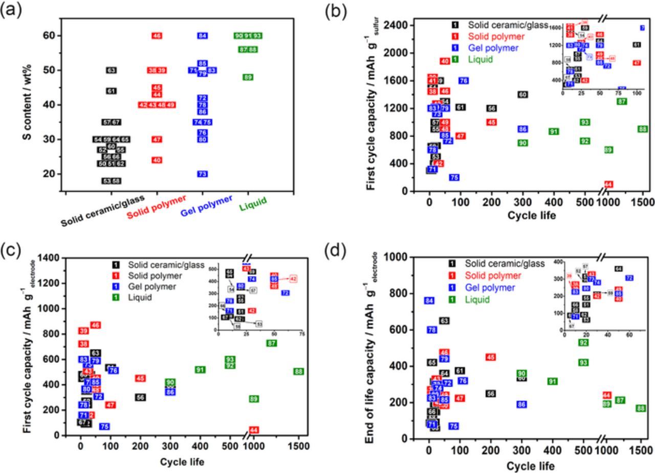
Figure 2. The state-of-art Li-S cells with various kinds of electrolyte: (a) S content vs. type of electrolyte; (b) first cycle discharge capacity in mAh g−1sulfur vs. cycle life; end of cycle life discharge capacity in (c) mAh g−1sulfur and (d) mAh g−1electrode vs. cycle life. The numbers in squares correspond to the references listed in Supplementary Information and color code corresponds to type of electrolyte.
ASSLSBs with relatively long cycle life have been presented in recent studies; however, the cell performance at the end of the cycle life is not competitive with the liquid system. Tatsumisago et al.48 reported that the Li-S cell using Li2S-P2S5 glass-ceramic electrolytes could deliver a discharge capacity of 249 mAh g−1electrode after 200 cycles. Liang et al.60 proved that the cycle life could be extended to 300 cycles with a good capacity of 336 mAh g−1electrode by introducing a new family of sulfur-rich compounds (Li3PS4+n) as active material. Hu et al.45 reported that the polymer Li-S cell was found to maintain good capacity retention after 200 cycles by using PEO-based electrolyte containing a novel type of lithium salt ([(CF3SO2)(n-C4F9SO2)N]Li). Recently, we evaluated the effect of lithium salt and ceramic fillers on the cycling performance of ASSLSBs using PEO-based electrolytes.48,49 Compared with other SPEs, the electrolyte consisting of lithium bis(fluorosulfonyl)imide (LiFSI) in PEO showed good compatibility with Li metal electrode without sacrificing the ionic conductivity at the operating temperature.48,94 By introducing Al2O3 or Li-ion conducting glass ceramic (LICGC) as inactive and active fillers, respectively, into the LiFSI/PEO polymer system, the electrochemical properties could be further improved. The composite polymer electrolyte (CPE) with nano-sized Al2O3 showed significant improvement of the Li/electrolyte interfacial properties, resulting in a good Coulombic efficiency (ca. 99%) of the Li-S cell, though accompanied by a relatively low S utilization (ca. 300 mAh g−1sulfur). More importantly, a high specific capacity of 1000 mAh g−1sulfur (areal capacity: 1.1 mAh cm−2) was achieved with CPE containing LICGC fillers. The Li-S cell with bilayer electrolytes (Li | Al2O3−CPE/LICGC−CPE | S) could deliver a discharge capacity of 900 mAh g−1sulfur at the first cycle with good capacity retention.49
Future Needs and Prospects
Application of solid electrolytes in Li-S batteries does not only facilitate the safe operation, but also benefits, in principle, the energy density at the cell level. Realistic calculations of energy density as a function of S loading, S utilization and electrolyte thickness will provide us useful guidance and key parameters for the design of ASSLSBs. Our previous calculation already demonstrated that solid electrolytes offer more room for improving the gravimetric energy density of Li-S batteries compared to liquid electrolytes based on the assumption that S utilization could reach 1000 mAh g−1sulfur in all cases.95 However, in practice, the specific capacity of Li-S batteries usually decreases upon increasing the S content due to the electronically insulating properties of S and Li2S. Therefore, we herein performed the calculation taking into account the variation in S utilization with different S contents and the results are presented in Fig. 3 (other parameters have been kept the same as our previous work79). Not surprisingly, when comparing with LIB (Li0) cells, Li-S batteries could be competitive in terms of gravimetric energy density (Wh kg−1) rather than in volumetric energy density (Wh L−1). The latter is likely due the low-density cathode materials, as well as the high fraction of inert components (carbon) required due to the poor electronic conductivity of elemental sulfur. The effect of electrolyte thickness on energy density is more dominant in ceramic electrolyte than in polymer electrolyte, since the former one normally has 2 to 5 times higher density. For a cathode with S content of 40 wt% and achievable S utilization of 1100 mAh g−1sulfur (Fig. 3a), the minimum areal capacities of ca. 1.5 mAh cm−2 for a polymer electrolyte with 50 μm thickness but a ceramic electrolyte with only 10 μm thickness are required for outperforming the LIB (Li0) technology. In addition, with increasing S content, both gravimetric and volumetric energy densities display little variation (Figs. 3a–3c) due to the reduced utilization of S. Under a possibly realistic but challenging S content (60 wt%, Fig. 3d), the gravimetric energy density for polymer electrolyte increases significantly with extending the degree of S utilization.

Figure 3. Estimated gravimetric (left) and volumetric (right) energy density of Li-S cells in solid electrolytes: (a) 40 wt% S content and 1100 mAh g−1sulfur S utilization, (b) 50 wt% S content and 900 mAh g−1sulfur S utilization, (c) 60 wt% S content and 600 mAh g−1sulfur S utilization, and (d) 60 wt% S content and various S utilizations.
ASSLSBs not only face the challenges coming from the solid electrolytes, like other types of all-solid-state batteries (e.g., low ionic conductivity, poor wetting properties), but also the intricate electrochemical redox reactions of S.34,96 The main challenges and accompanying possible solutions are summarized below.
(1) The quest for highly Li-ion conductive solid electrolyte with good processability
The Li-ion conductivity of solid electrolyte plays a pivotal role in determining the rate performance of Li-S batteries, while the effect of temperature on ionic conductivity has been proved to be significant, especially for those PEO-based electrolytes. For example, around room temperature region, the ionic conductivity of PEO-based PEs normally locates in the order of 10−5–10−6 S cm−1,49,97 though it can be further increased to ca. 10−4 S cm−1 above the melting transition of PEO (60−65° C). This requires an operating temperature higher than 60°C for the PEO-based ASSLSBs, as seen in Table I.38–43,45,46,48,49 In comparison, the dependence of conductivity on temperature for ceramic electrolytes generally follows a continuous Arrhenius trend. For example, the lithium superionic conductor, Li10GeP2S12, holds an extremely high bulk conductivity of > 10−2 S cm−1 at 25 °C, and reaches 10−1 S cm−1 at 100 °C with an activation energy of 24 kJ mol−1 for ionic conduction.98
Overall, PEs provide good elastomeric properties, but relatively lower ionic conductivity compared to ceramic electrolytes at the room temperature. Both the structural modification of polymer matrix and the development of new lithium salts are highly desired for enhancing the ionic conductivity of PEs. Recently, a high ionic conductivity of 4.5 × 10⁻⁵ S cm−1 at room temperature was achieved by a new type of comb polymer material based on polyether amines oligomer side chains (i.e., Jeffamine compounds),99 which can thus be a good candidate for operating polymer-based ASSLSBs around room temperature. On the other hand, ceramic electrolytes hold the advantages in Li-ion conductivity and absence of solubility for polysulfide species, but their application is plagued by the poor processability. Combining the merits of polymer and ceramic together, the blend electrolytes of polymer and ceramic solid electrolytes could lead to a possible breakthrough in ASSLSBs batteries, boosting a synergetic effect of both systems. Effectively, several types of ceramic electrolytes have recently been integrated into polymer electrolytes for enhancing their physiochemical and electrochemical properties, such as those using NASICON (Li1.4Al0.4Ge1.7(PO4)3,100 LICGC (Li1+x+yAlxTi2-xSiyP3-yO12),49 and Li1.3Al0.3Ti1.7(PO4)3 (LATP)97,101), perovskite (Li0.33La0.557TiO3 (LLTO)102,103), and garnet (Li7La3Zr2O12 (LLZO).104,105
(2) A good contact of solid/solid interphase
Decreasing the charge-transfer resistance between the electrodes and solid electrolyte etc. presents an enormous challenge, which requires a good contact of the two solid/solid components, especially when considering the volume expansion and contraction of the S cathode undergoes upon discharge/charge cycles. This challenge will be magnified in ASSLSBs with true ceramic electrolyte, as clearly seen from Table I and Fig. 2 that high C-rate discharge/charge and long-term cycling are less revealed in the state-of-art work.
In order to improve the contact between electrodes and solid electrolytes, the composite electrolytes comprising of ceramic electrolyte layer and either liquid or polymer electrolytes are proposed. Hagen et al.106 utilized a composite electrolyte consisting of a glass ceramic electrolyte (Li2O-Al2O3-SiO2-P2O5-TiO2-GeO2) and 1 M LiTFSI-DME/DOL liquid electrolyte. Though successful operation of the corresponding Li-S cell was achieved, only several cycles at a low rate of C/100 was reported. Follow the similar concept, Wen et al.68 exhibited that with LATP and 1 M LiTFSI-DME/DOL composite electrolytes, the shuttle effect of PS was suppressed and the contact of solid/solid interphase was significantly improved. Very recently, Wachsman and Hu et al.107–109 proposed several surface treatment methods on Li metal anode for reducing the interfacial impedance between Li metal anode and solid electrolytes, such as Al2O3107,108 and germanium layers.109 Besides, they conceived a three-dimensional bilayer electrolyte framework for enhancing the interfacial contact of ASSLSBs.69 The dense garnet layer with a few microns thickness retained good mechanical stability, and blocked polysulfide diffusion and impeded Li dendrite formation; the thick porous garnet layer acted as a mechanical support for the thin dense layer, as well as enabled continuous Li+/electron pathways to host the sulfur cathode. These methods offer an excellent chance to increase the cycle-life and S loading of ASSLSBs.
Apart from the strategies mentioned above, we suggest that the integration of polymeric components into ceramic electrolyte could help to minimize the contact problem, e.g., with a mixture of ceramic and polymer in the S cathode, and surface treatment of ceramic electrolyte with organic functional moieties.110,111
(3) An in-depth understanding of ASSLSBs
The discharge/charge mechanism can be affected by the identity and quantity of solvent and lithium salt, as proved by the several recent reports in liquid electrolytes.31,32,112 However, an in-depth understanding in the reaction mechanism of ASSLSBs, a necessary step for improving further the cycling performances, is seldom presented in the literature. In addition, the surface characterizations on Li metal and S cathode have been well studied in liquid system, but far less so with solid electrolyte, especially for those PEs-based Li-S cells.
In recent years, a few advanced techniques have been developed to probe sulfur speciation and to understand the exact redox chemistry as well as capacity fading of ceramic electrolyte-based ASSLSBs. Kanno et al.113 reported the ex situ X-ray scattering study of Li-S cell with thio-LISICON (Li3.25Ge0.25P0.75S4) electrolyte. The formation of two Li2S phases during the discharge reaction and the strong interaction between sulfur and carbon layer was confirmed. This suggests that modifying the structure of the sulfur/carbon composite is important for improving the capacity and cycling characteristics of ASSLSBs. Tatsumisago et al.58 employed cross-sectional transmission electron microscopy (TEM) and electron-energy-loss spectroscopy (EELS) to reveal the importance of realizing intimate contact among electrode components and reducing the particle size of active composite electrodes. Through high-resolution TEM and energy dispersed X-ray (EDX) spectroscopy experiments, Tatsumisago et al.66 also showed reversible structural and morphological changes at the nano-scale during the discharge/charge cycles in ceramic electrolyte-based ASSLSBs. To avoid possible side effects and inaccuracy emanating from post-treatment of samples, various advanced in situ and operando techniques have been recently applied for Li-S cell using liquid electrolytes. These tools provide the real-time dynamic picture of the electrochemical process on operating Li-S cells. Nelson et al.114 reported on the use of operando XRD and transition X-microscopy on Li-S system and demonstrated results that contradict to those obtained by ex situ studies. Operando X-ray absorption spectroscopy (XAS),115 in situ X-ray absorption near-edge structure (XANES),116 and in situ X-ray fluorescence (XRF)16 have been used to investigate the sulfur speciation in operating Li-S system. Other operando characterization tools such as ultraviolet-visible spectroscopy (UVS), electron paramagnetic resonance (EPR) as well as in situ7 Li NMR,18 high-performance liquid chromatography-mass spectroscopy (HPLC-MS)117 etc to gain an in-depth understanding of the Li-S system.
Though the emerging of in situ, operando techniques and other combination of arsenal tools have advanced the knowledge on Li-S, the utilization theoretical studies and chemical simulations are of paramount importance to have further in-depth understanding of the ASSLSBs. For instance, using results obtained from DME-based liquid solution could be used to mimic and thereby correlate the ones from PEO-based PEs, owing to the fact that DME is the low-molecular weight analogue of PEO. Still, the techniques to understand the exact reaction mechanism between the Li/PEs or ceramics and cathode/PEs or ceramics are missed and deserve further exploration in the future.
Conclusions
Li-S batteries have emerged as important candidates for future energy storage systems; especially for applications which remand high gravimetric energy densities. All-solid-state Li-S batteries (ASSLSBs) offer a chance not only to be safer than those using liquid electrolytes, but also to achieve higher gravimetric energy densities than the state-of-art Li-ion batteries. Current research works on ASSLSBs using either inorganic or organic polymer electrolytes or their composite mixture showed sufficiently high S utilization at initial cycles; however, the cyclability and areal capacity of ASSLSBs are still far from the practical requirements. The future development of ASSLSBs needs to overcome the challenges including in most cases low Li-ion conductivity, poor processability and solid-solid contact, lack of in-depth understanding of S redox chemistry in solid electrolytes, and the choice of ad-hoc techniques to probe in details the interfacial properties. With the possible solutions mentioned in this review and great efforts that are being dedicated to this field, we could anticipate that ASSLSBs will be an excellent choice for safe and high gravimetric energy storage system in the future. Moreover, we strongly believe that new findings, understandings, and insights into the Li-S chemistry, interfacial processes and cathode-anode interactions will synergistically bring ASSLSBs much closer to commercial reality.
Acknowledgments
This work was supported by GV-ELKARTEK-2016 from the Basque Government, and MINECO RETOS (Ref: ENE2015-64907-C2-1-R) from Spanish Government. X. J. thanks the Government of the Basque Country for funding through a Ph.D. Fellowship, and C.L. thanks the Juan de la Cierva scholarship (Ref: FJCI-2015-23898).
ORCID
Heng Zhang 0000-0002-8811-6336
Chunmei Li 0000-0003-4438-0458