Abstract
In our prior study, ultraviolet (UV) light was used for the first time to improve long-term cycling of lithium-ion battery (LIB) electrodes. It was found that UV treatment of the anode resulted in thinner solid electrolyte interphase (SEI) layers, higher capacity retentions, and lower charge transfer resistance after cycling. In this study, pristine graphite powders and polyvinylidene fluoride films (binder) with/without UV treatment were individually analyzed before cell assemblies. X-ray photoelectron spectroscopy (XPS) analysis showed a 300% increase in atomic percentage of oxygen on the graphite powder surfaces after UV treatment. However, fluorine level of the binder film decreased by more than 10%. The PVDF film also expanded in thickness by 3.7% after the UV treatment for 40 minutes, indicating scissions of the polymer backbones. The changes in PVDF weight, thickness, and fluorine atomic percentage from XPS peaks also indicated the release of fluorine containing gases (e.g., hydrogen fluoride and difluoroethylene gas) after crosslinking and scission of the PVDF. Although UV light was found to partially decompose PVDF in this study, it helped to increase oxygen level on the graphite, which, resulted in a thinner SEI layer, lower resistance, and eventually higher capacity retention as shown in our prior study.
Export citation and abstract BibTeX RIS

This is an open access article distributed under the terms of the Creative Commons Attribution 4.0 License (CC BY, http://creativecommons.org/licenses/by/4.0/), which permits unrestricted reuse of the work in any medium, provided the original work is properly cited.
During lithium-ion battery (LIB) production, formation cycles, where solid electrolyte interphase (SEI) is formed, are one of the most important processes significantly affecting the coulombic efficiency and even cycle life.1–3 SEI formation is highly dependent on surface properties of the graphite which determines electrolyte wettability4 and reduction potential.1,5–7 The presence of oxygen groups on graphite surfaces is beneficial to SEI formation and mitigates graphite exfoliation.8,9 Heat treatment is a typical method to control oxygen levels on graphite surfaces performed at several hundred degrees Celsius in an oxygen rich or inert (e.g., Ar) environment to introduce or remove oxygen groups, respectively.10 Acidic chemical treatments have also been used for oxygen formation.10 Both methods have certain drawbacks such as high cost and long processing time for the heat treatments and potential damage to graphite for the chemical treatments. Electron beam irradiation also changes the surface structure of the carbon materials and modifies binder components from the electrode surface.11,12 3 To the best of our knowledge, ultraviolet (UV) light treatment has not been used in battery applications although this technique is commonly used in carbon-fiber reinforced polymer industries.13,14 The UV process could be inserted immediately following an electrode coating process to be compatible with roll-to-roll processing without a significant modification of other existing processes.
In our prior study,3 UV light (UVA wavelength of 320–390 nm) was used for the first time to control oxygen levels on graphite anodes and improve their electrochemical performance in full 1.5 Ah pouch cells with A12 graphite (ConocoPhillips) and Li1.02Ni0.50Mn0.29Co0.19O2 (NMC 532 TODA America Inc.) produced at the DOE Battery Manufacturing R&D Facility at ORNL (BMF). It has been demonstrated that 40-minute UV light treatment on the anode was the optimal condition resulting in the thinnest SEI layer, the highest capacity retention (Figure 1), and the smallest increase in the charge transfer resistance. The prior study focused on electrochemical performance and surface chemical analysis on composite electrodes consisting of graphite particles, carbon black and polyvinylidene fluoride (PVDF) binders together. In this work, extra efforts have been made to characterize and distinguish the effect of UV light treatment on individual electrode constituents where graphite particles and PVDF polymer were individually treated under UV light. X-ray photoelectron spectroscopy (XPS, K-Alpha, Thermo Scientific) was used to analyze elemental changes on the surfaces of graphite powder and PVDF polymer films. A high precision balance and caliper were used to measure weight and thickness changes of the materials.
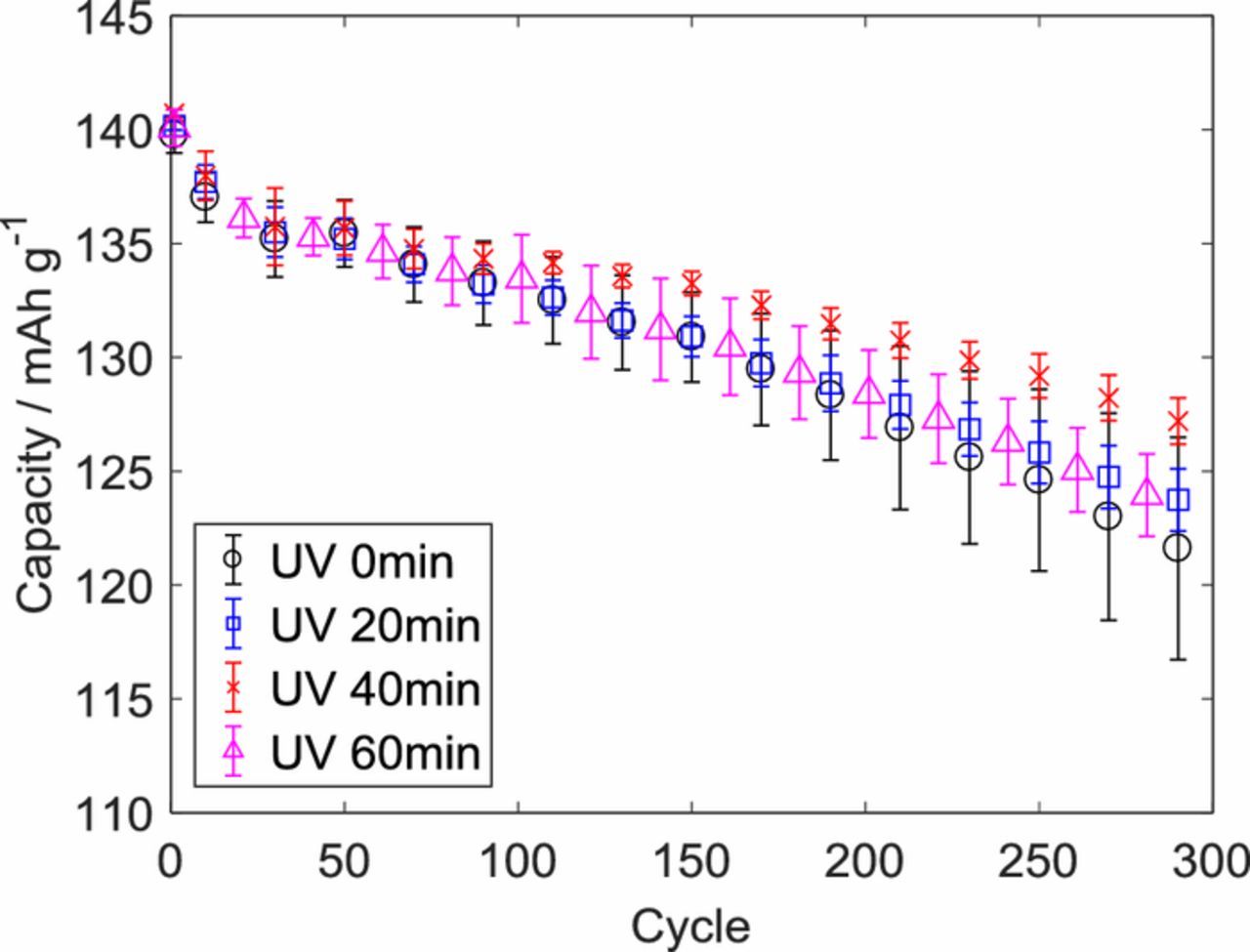
Figure 1. Average discharge capacities with 90% confidence intervals (error bars) from cycle life tests with 1C charge and discharge rates from the prior study in full 1.5 Ah pouch cells with A12 graphite (ConocoPhillips) and Li1.02Ni0.50Mn0.29Co0.19O2 (NMC 532 TODA America Inc.). Reproduced with permission from J. Electrochem. Soc., 163, A2866 (2016). Copyright 2016, The Electrochemical Society.3
Experimental
A12 graphite powder (ConocoPhillips) was carefully placed on double-sided tape attached to a glass plate, and the top layer of the powder was compressed using another clean glass plate such that the powder adhered to the double-sided tape. The layer of powder was thick and fully covered the tape, and this coverage prevented the UV light and XPS incident beam from reaching directly to the tape or glass plate. One sample was treated with UV light for 40 minutes, and the UV treatment was carried out using a 5000-EC UV curing lamp (Dymax Corp.) delivering concentrated light primarily in the UVA range (320–390 nm) to achieve maximum UV penetration depths. UVA penetrates into a substrate more than UVB where UVB penetrates 100 μm depth with 90% of the incident intensity in case of carbonate sand.15 Thus, UVA used in this study can penetrate through the 65 μm thick anodes with more than 90% of the incident. Another sample was not treated with UV to serve as a control comparison. These two samples were then dried overnight at 700 mbar and 80°C in a vacuum chamber located in a dry room. Next, they were transferred to the XPS chamber using a vacuum transfer module to obtain surface chemistry information. A 400 μm X-ray beam was used for survey scans to obtain average percentages of the elements in a large area of a sample. A flood gun was turned on to avoid any charge buildup on the samples, which were placed on a glass plate.
A PVDF film was coated by a doctor blade (20 cm width, Pacific Scientific, Gardner Neo Tec.) on a Cu foil using 8% PVDF solution (9300 Kureha, MW > 1 × 10⁶ g/mol, melting temperature = 163°C, crystallization temperature = 136°C), which was the same binder solution used in the previous work.3 The PVDF film was dried at 132°C inside a dry room with RH < 0.1% and cut into one large sheet and several small sheets. The large sheet was used for measurements of weight and thickness before and after the 40-minute UV treatment. A precision balance (HR-202i, A&D) with 0.01 mg resolution and a precision micrometer (IP65, Mitutoyo) with 0.001 mm resolution were used for the weight and thickness measurements, respectively. One small sheet was treated with UV for 40 minutes and another one was not treated as a control. The surface chemistry of each sample was analyzed via XPS.
Results and Discussion
Graphite surface functionality with and without UV treatment
Elemental analysis was conducted on pure graphite powder, and XPS survey scans showed that the percentage of oxygen on the graphite surfaces increased by a factor of 3.4 after a 40-minute UV treatment (Figure 2). Figure 3 shows the peak analysis, and 531.8 eV and 532.5 eV were assigned to the peak centers of C=O and C-O-H in O1s narrow scans, respectively (Figures 3a and 3b). For peak centers in C1s narrow scans (Figures 3c and 3d), 284.6 eV, 285.5 eV, 286.3 eV, 287.1 eV, 288.6 eV, 291.3 eV were assigned to C-C sp2, C-C sp3, C-OH, C-O-C, C=O, and O=C-OH, respectively. XPS narrow scans for O1s indicated that hydroxyl group prevalence increased from 23% to 55% within the oxygen content after the 40-minute UV treatment while carbonyl group content decreased from 77% to 45% (Figure 3 and Table I). The scan for C1s also showed that hydroxyl groups on carbon increased from 5.9% to 7.6% of the carbon content. Carbonyl groups from C1s increased from 3.1% to 8.6% but carboxyl groups having C=O decreased from 8.8% to 2.3%. Hence, the net carbon percentage from C=O decreased after the UV treatment, which is in agreement with the decrease in oxygen percentage from C=O in O1s peaks. Like the O1s peaks and peaks from survey scans, the C1s peaks showed that the percentage of carbon with oxygen groups increased after the UV treatment.
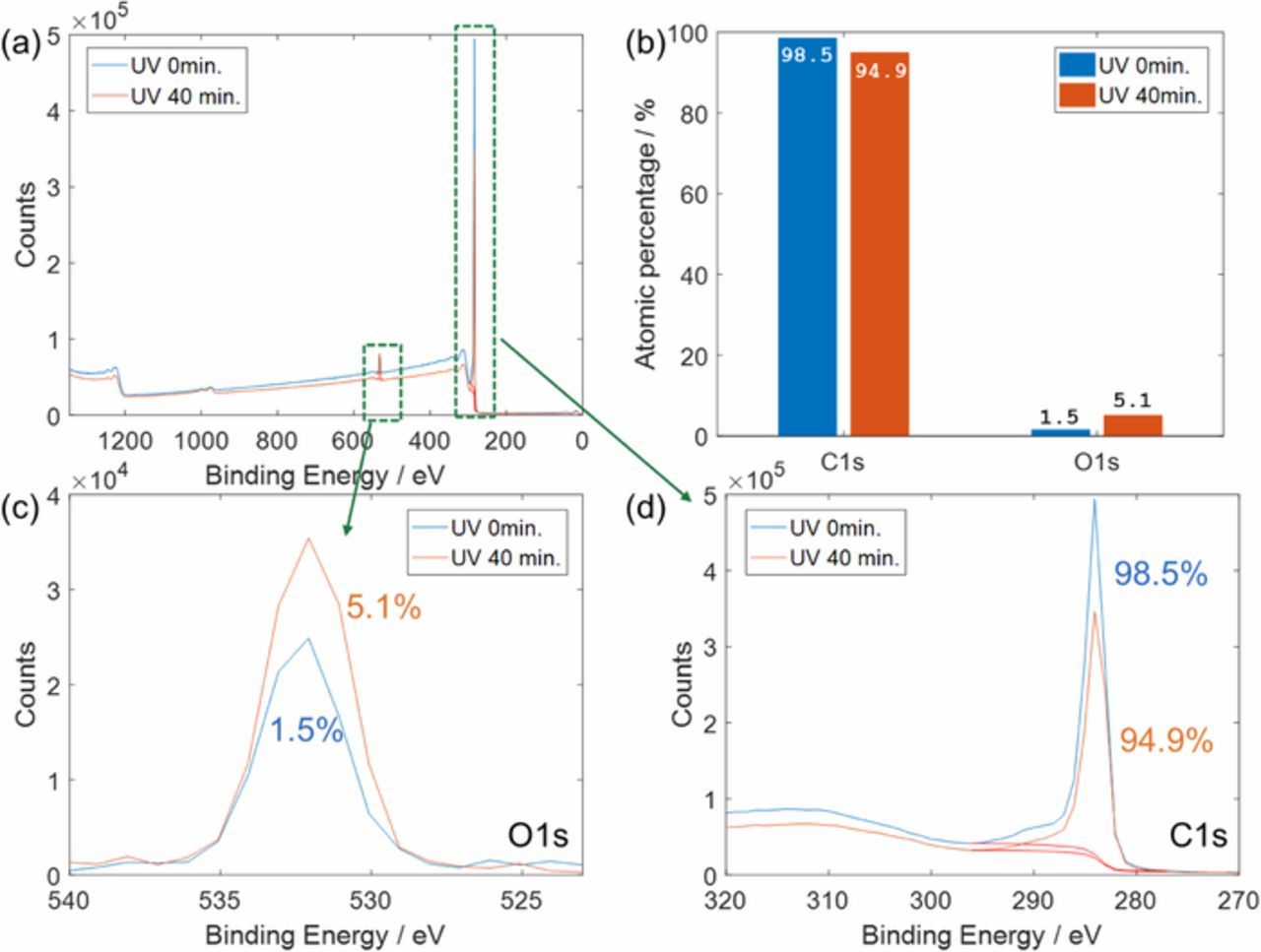
Figure 2. XPS survey scan results on A12 graphite powders before UV treatment and after UV treatment for 40 minutes (a), atomic percentages of carbon and oxygen calculated from the survey scans (b), and narrow scan results for O1s (c) and C1s (d).
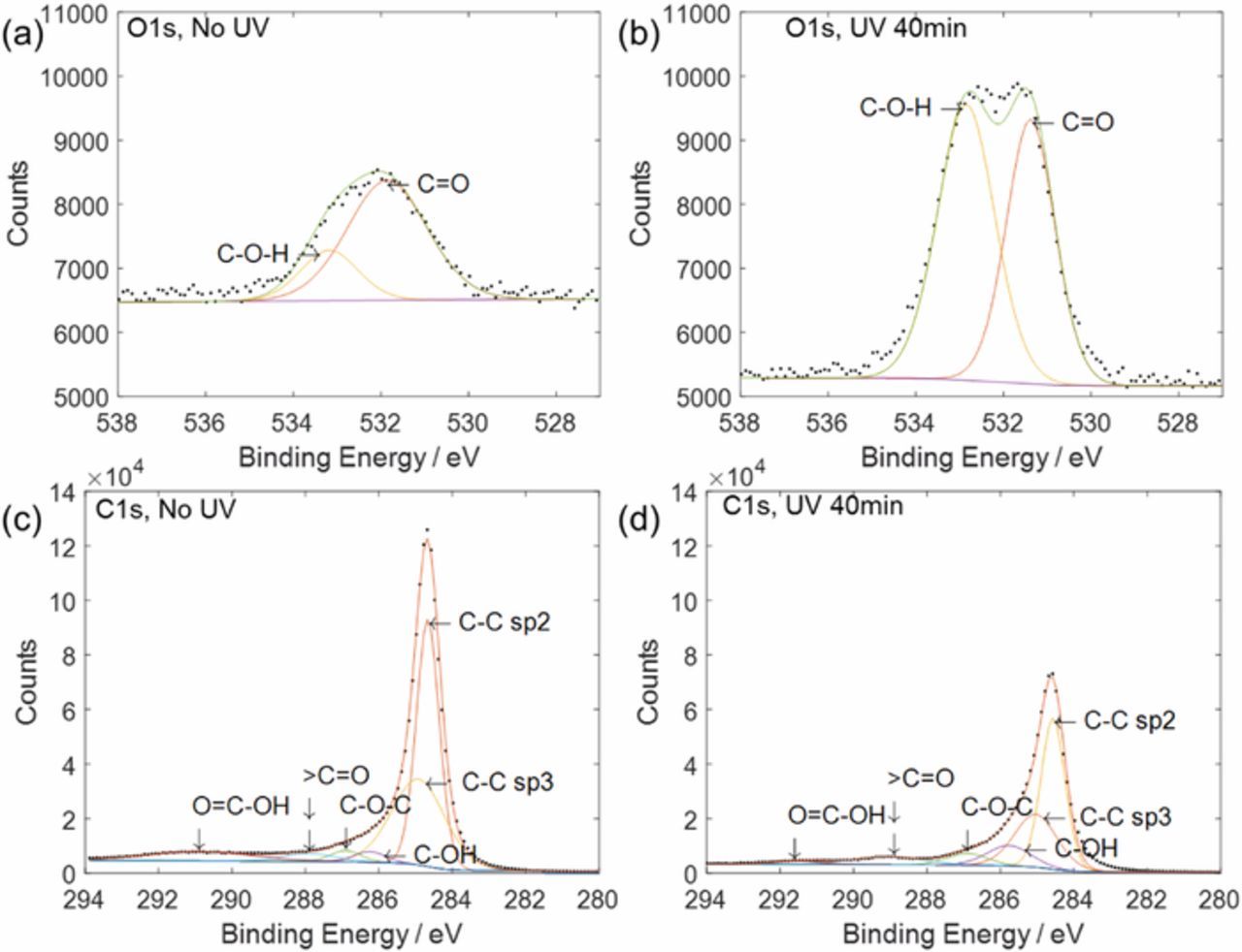
Figure 3. XPS narrow scan results of O1s before UV treatment (a) and after UV treatment for 40 minutes (b) and C1s before UV treatment (c) and after UV treatment for 40 minutes (d).
Table I. XPS results on graphite before UV treatment and after the treatment for 40 minutes from narrow scans for O1s and C1s.
| Peak | Element | No UV | UV 40 min |
|---|---|---|---|
| O1s | C-O-H | 23.24 | 55.15 |
| C=O | 76.76 | 44.85 | |
| C1s | C-C (Gr) | 79.4 | 77.8 |
| C-OH | 5.92 | 7.59 | |
| C-O-C | 2.86 | 3.81 | |
| >C=O | 3.06 | 8.55 | |
| O=C-OH | 8.8 | 2.28 |
Figure 4 shows a mechanism proposed in this study for increasing hydroxyl group concentration on a graphite surface. Graphite has defects and edges where oxygen groups can attach. Typical oxygen groups found on a graphite surface are carbonyl, epoxide, hydroxyl, and carboxyl groups.8,16 Since the UV treatment was carried out under atmospheric conditions with moisture present, the source of additional hydroxyl groups on the graphite surfaces likely came from water in the air.13 Possible water reactions under UV light are proposed as Reactions 1 and 2.17
![Equation ([1])](https://content.cld.iop.org/journals/1945-7111/166/6/A1121/revision1/d0001.gif)
![Equation ([2])](https://content.cld.iop.org/journals/1945-7111/166/6/A1121/revision1/d0002.gif)
These splits may not occur with water alone in the UVA range due to low absorption. However, these reactions can occur when graphite surfaces and heat induced by UV are accounted for. Surface temperatures of the electrodes were close to 100°C (Table II). The temperatures were measured on electrodes using a portable infrared thermometer immediately after UV treatments for different periods of time. Hence, temperature during the UV treatment would have been higher than the results shown in Table II.
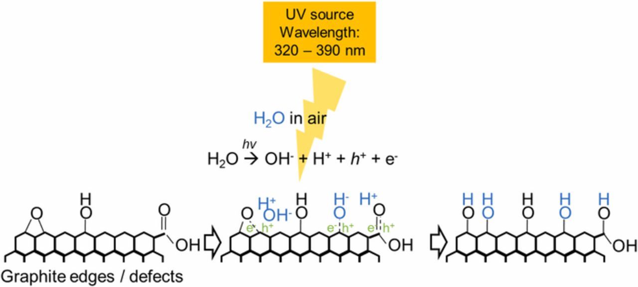
Figure 4. A proposed pathway for additions of hydroxyl groups on a graphite surface under UV light with humid air.
Table II. Temperature on electrode immediately after UV treatment with different periods of time.
| Time for UV treatment/min | Temperature on electrode side/°C |
|---|---|
| 0 | 23 |
| 20 | 93.5 |
| 40 | 93 |
| 60 | 97.5 |
Changes in PVDF after UV treatment
Figure 5 shows the thickness and weight changes of electrodes and PVDF films after the UV treatment. The weight changes of PVDF in the electrodes were calculated based on the assumption that the weight changes in the electrodes occur only from the PVDF binder. Average thickness of the PVDF films was 4.5 μm from six measurements before UV treatment. After the 40-minute UV treatment, the average thickness increased by 0.167 μm, which corresponds to a 3.7% increase. It should be pointed out that the resolution of the micrometer was 1 μm; however, the PVDF film thicknesses were consistently higher after the UV treatment.
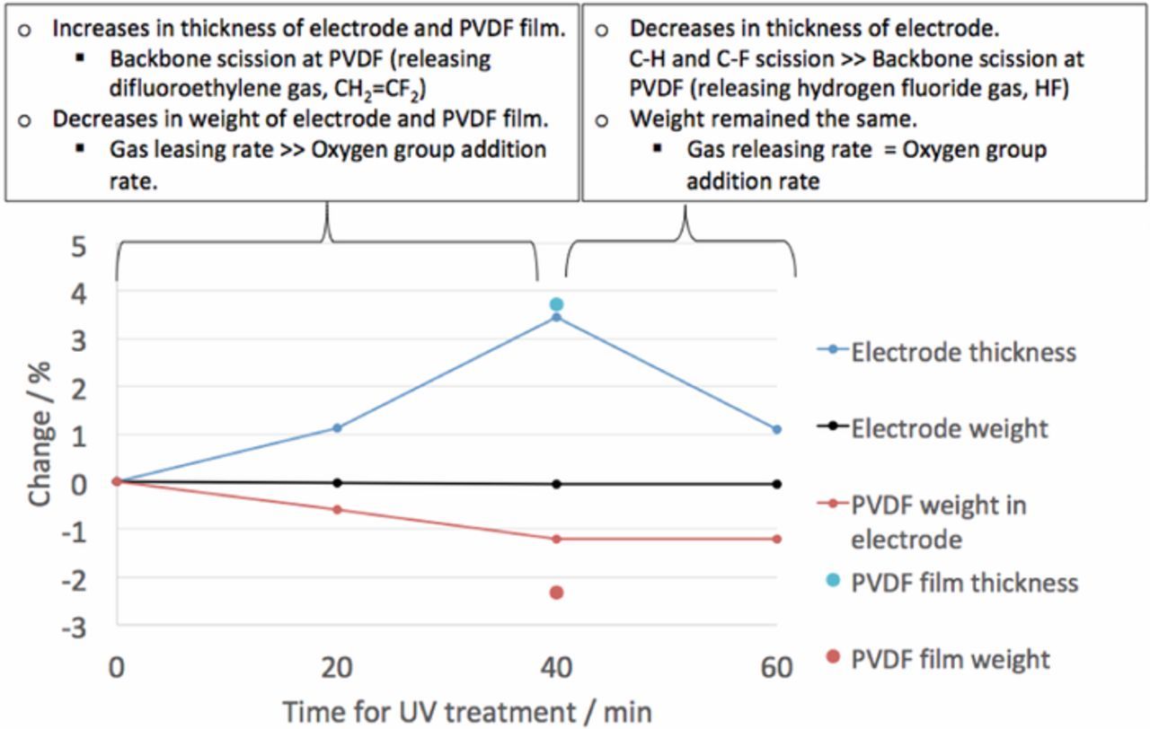
Figure 5. Weights and thicknesses of electrodes and PVDF films after UV treatment with different periods of time.
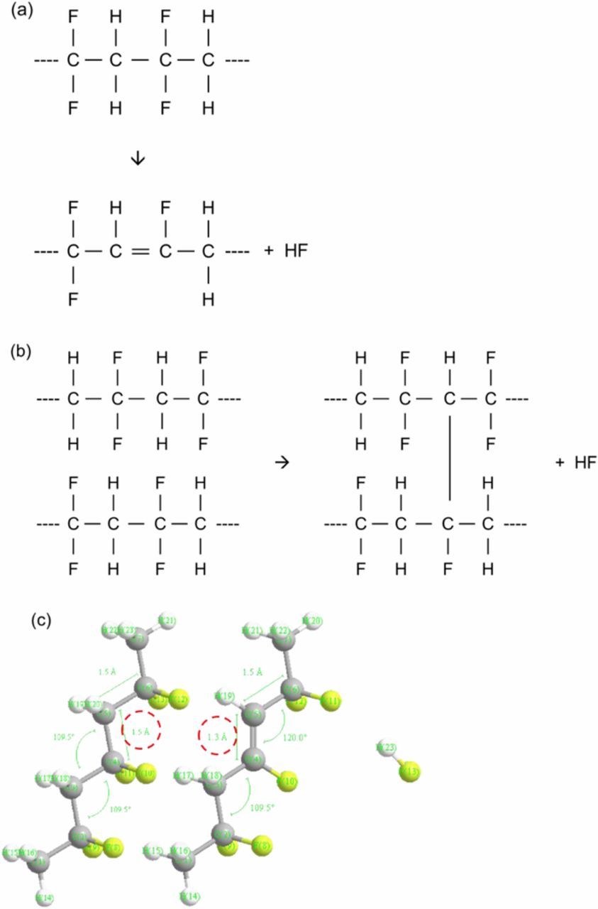
In general, thickness of a PVDF film can increase when the film experiences backbone scissions, resulting in polymer chain disconnections (Figure 6).18 This backbone scission explains the thickness increase during the 40-minute UV treatment. Similar thickness changes were obtained at the anode containing both graphite and PVDF binders during 40 minutes of the treatment, but the thickness decreased from 40 minutes to 60 minutes. The PVDF thickness reduces when C-H and C-F scissions occur, resulting in cross-linking between polymer chains or creation of double bonds in the polymer backbones (Figures 7a and 7b).18,19 The carbon-to-carbon distances and angles of PVDF with and without a double bond were calculated in Figure 7c using Chem3D (CambridgeSoft Co.). This crosslinking in polymer chains may negatively affect the volume expansion of graphite during lithiation and could explain why there was an optimum UV exposure time.
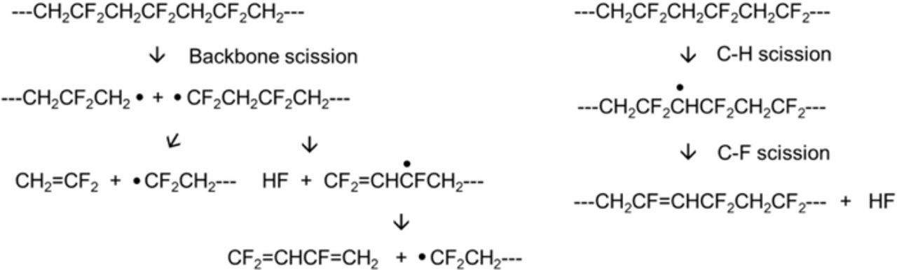
It is reasonable that backbone scissions happen under UV treatment before C-H and C-F scissions since C-H and C-F bonds are stronger than C-C backbones. This scission sequence explains the thickness changes in Figure 5. Although the micrometer did not have enough precision for measurements involving submicron thickness changes, the results from the average thickness changes were plausible and are explained by the different scission processes. These scissions involve release of difluoroethylene and hydrogen fluoride gases and cause weight loss in the PVDF film, a result that was also observed in this study (Figure 5). The results from the XPS survey scans showed that the weight loss after the 40-minute UV treatment was ascribed to fluorine loss (Figure 8), which agreed well with the weight changes in Figure 5.
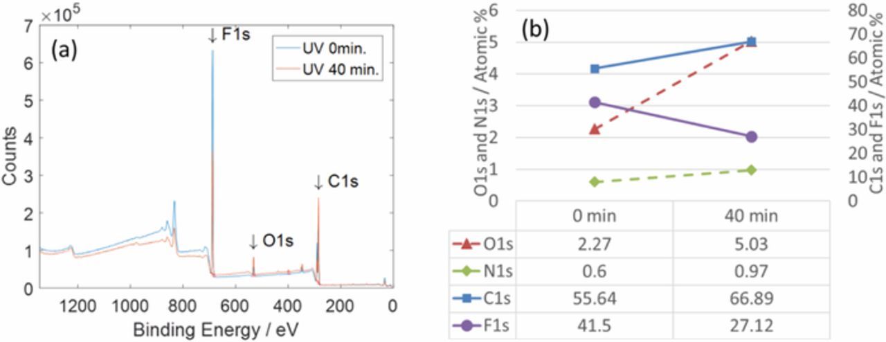
Figure 8. XPS survey scans from PVDF films before UV treatment and after the treatment for 40 minutes (a) and atomic percentages from the scans (b).
From 40 minutes to 60 minutes in the treatment, the weight of the electrode did not change appreciably. The total electrode weight might not change after 40 minutes when the removal rate of fluorine atoms from the graphite surfaces is competing with the addition rate of oxygen and hydrogen. A large increase in the oxygen percentage after the UV treatment in Figure 8 indicates the addition of oxygen occurred. In our prior study, aging tests showed that the cells having anodes that underwent a UV treatment for 60 minutes showed lower capacity retention than those in undergoing a 40 minute treatment.3 This decrease in the capacity retention after 40 minutes probably likely occurs from combined effects of changes in the PVDF binder and oxygen group on the graphite.
Conclusions
UV light was applied to lithium ion battery electrodes for the first time to control oxygen levels on the anode and improve battery cycle life in our prior study. In this study, A12 graphite powder and PVDF binder were individually treated under UV light so that the individual effects of UV could be separated. It was found that UV light with humid air increased oxygen levels, particularly in hydroxyl form, on graphite surfaces. On the other hand, UV caused decreases in fluorine levels in PVDF after scissions and cross-linking of the polymer chains releasing fluorine containing gases (e.g. hydrogen fluoride and difluoroethylene). This increase in oxygen levels on graphite is believed to improve SEI formation and cycle life of lithium ion batteries although PVDF degrades slightly.
After observing the positive UV effects, other approaches may be considered to shorten treatment time. Possible approaches are the use of oxygen or ozone instead of air, an increase in humidity (moisture level), and the use of high-power UV. Oxygen radicals might be effective as well. H2O2 could be considered as it produces OH radicals under UV. Furthermore, different UV ranges would be a factor in controlling the oxygen level. In our prior study, the UV treatment was conducted on coated and dried anodes to add oxygen groups on the anode surface because this process is effective and can be easily applied to other existing processes. However, if raw graphite powder were treated with UV light first and then coated on current collectors, oxygen groups would be more uniformly distributed on the graphite surfaces throughout the coated electrode. In this pretreatment configuration, changes (or removals) of the oxygen groups would need to be confirmed after the mixing and coating processes.
Acknowledgments
This material is based upon work supported by the U. S. Department of Energy (DOE), Office of Energy Efficiency and Renewable Energy (EERE) Vehicle Technologies Office (VTO) (Deputy Director: David Howell) Applied Battery Research subprogram (Program Manager: Peter Faguy) under contract DE-AC05-00OR22725.