Abstract
While the electrification of the transportation sector is underway with a consistently increasing market share, segments like light commercial vehicles (LCVs) have not seen any significant market penetration. The major barriers are primarily in the shortcomings in specific energy, power, and cost associated with Li-ion batteries. With an initiative from several automakers to electrify other segments, there is a need to critically examine the performance requirements and to understand the factors governing such a transition in the near-term and long-term. In this study, we develop a systematic methodological framework to analyze the performance demands for electrification through an approach that couples considerations for battery chemistries, load profiles based on a set of vehicle-specific drive cycles, and finally applying these loads to a battery pack that solves a 1-D thermally coupled battery model within the AutoLion-ST framework. Using this framework, we analyze the performance of a fully electric LCV over its lifetime under various driving conditions and explore the trade-offs between battery metrics and vehicle design parameters. We find that in order to enable a driving range of over 400-miles for LCVs at a realistic battery pack weight, specific energies of over 400 Wh/kg at the cell-level and 200 Wh/kg at the pack-level needs to be achieved. A crucial factor that could bring down both the energy requirements and cost is through a vehicle re-design that lowers the drag coefficient to about 0.3.
Export citation and abstract BibTeX RIS

This is an open access article distributed under the terms of the Creative Commons Attribution 4.0 License (CC BY, http://creativecommons.org/licenses/by/4.0/), which permits unrestricted reuse of the work in any medium, provided the original work is properly cited.
The complete electrification of the transportation sector is essential to reduce CO2 emissions and improve air quality in densely populated cities.1 There has been remarkable progress toward electrification in the passenger sedan market, with a market share of more than a few hundred thousand vehicles, and reaching as high as 23% in Norway and 10% Netherlands.2 Light commercial vehicles (LCVs) form nearly one-tenth of the global market share3 and about 30% in the United States where they account for approximately 30% of the greenhouse gas emissions of the transportation sector.4 Yet, the electrification of this segment is very limited, primarily due to the shortcomings of the current state of battery technology.5–8 The average fuel economy for this segment has remained largely stagnant since 1985, while the engine fuel efficiency has been increasing continuously.9 This is in large part due to automakers increasing the performance of the vehicles at the expense of fuel economy, thus, maintaining sustained demand for high-performance LCVs.
Prior work has explored the implementation of hybrid electric pickup trucks10 with the drivetrains utilizing internal combustion engines (ICEs) for longer distances. A few other studies11,12 have discussed the potential use of a battery pack by retrofitting conventional pickup trucks with electric drivetrains. With major electric automakers such as Tesla Inc., announcing their work toward fully electric LCVs,13 there is an urgent need to understand systematically the performance of the battery pack in real-world driving conditions over long periods of time and to study the implications of improved specific energy, power, and vehicle design. To do this, we need to have a framework where each design criterion is carefully analyzed to determine its impact on, firstly, the battery pack requirements, secondly, battery health over the pack's lifetime, and finally, the consequent effect on the overall cost of the battery pack. Each of these aspects is crucial to consider while directing research and development efforts to accelerate the electrification of LCVs.
The goal of this study is to identify the performance requirements required for realistic electric LCVs and to understand the interplay between battery metrics, vehicle design, and the cost of the battery pack required to enable mass electrification. Our approach and analysis leverage the pioneering work done by John Newman in modeling of electrochemical systems bridging length and time scales.14–20 In our approach, the battery specific parameters are obtained from the design and characterization of single cells on a thermally coupled battery (TCB) model often termed as the Newman model, solved using AutoLion-1D. We first address the question of how current Li-ion battery chemistries perform in facilitating the electrification of a benchmark LCV, the Ford F-150, with cost inputs from a reliable open-source cost model based on BatPaC. For the most suitable battery chemistry, we examine the pack health by conducting an aging performance analysis where the battery packs are modeled and simulated using the TCB model to study the effect of driving profiles and ambient conditions on pack life. We find that current battery chemistries, under the limits of a driving range of 200-miles and 1000 kg of payload capacity, one could design a reasonably efficient fully electric LCV, and the pack could last over 1000 cycles or 200,000 miles with a 10% loss in pack capacity.
However, the cost of the pack is identified to be a key limiting factor ranging between ∼$30,000 and $50,000 depending on the battery chemistry. Attempting to extend the range from 200-miles to 400-miles would increase these bounds to ∼$60,000 and $140,000 respectively. Enabling a higher payload capacity of over 2000 kg with the limited range of 200-miles results in an overall inefficient system with the battery pack weighing more than 50% of the curb weight of the vehicle along with an increase in cost/ pack of up to $10,000, these trade-offs are examined in detail for the different parameters. Finally, we examine the potential improvements that could be obtained with advanced Li-ion batteries, and beyond Li-ion systems like Li-S and Li-air, and we find that after a certain value of specific energy the battery pack weight becomes less significant and results in minimal improvements in performance metrics of the vehicle.
Methods
We first develop the approach to estimate the energy demands of an LCV in real-world conditions and to determine the pack energy required to meet these demands, with a careful consideration of the effects of the weight of the battery pack. The weight of the pack, dictated by the specific cell chemistry, is incorporated via cell design and characterization conducted on a TCB model. We then examine the requirements for electrifying a benchmark LCV, a Ford F-150, within a base case scenario. Using aging performance analysis of the pack on the TCB model we look at how the pack health can be studied for different conditions of use. In parallel, we develop a cost model within BatPaC to compare the different battery packs considered. Finally, in order to examine the changes that could be brought about at the system-level through vehicle design and specific energy of the pack, we propose the use of the parameter called pack-to-curb weight ratio.
Power and energy requirements
The first step involves getting an estimate of the power and energy requirements under different conditions of use. The power load of a vehicle can be determined with instantaneous velocity profile, v(t), over a specific trip distance. This data for LCVs and pickup trucks was obtained from a study by Liu et al.,21 who have employed a method of 'naturalistic drive cycle synthesis', to construct representative categories using real-world data from the Transportation Secure Data Center (TSDC) of the National Renewable Energy Laboratory.22 The driving conditions identified in their work are Congested-Urban (CU), Uncongested-Urban (UU), Urban-Suburban (US), Urban-Suburban-Highway (USH), and Highway (HW). As detailed in their study, Liu et al.,21 examine the naturalistic drive cycle data for pickup trucks from TSDC to procure small sections of drive cycles called 'micro-trips' which are categorized according to metrics like mean velocity and trip duration. After considering the probability of a vehicle transitioning from one micro-trip to another, these micro-trips are clustered together to form a large set of new drive cycles using Markov Chain theory. Based on well-defined criteria for representativeness of a driving condition like the standard deviations of velocity and acceleration, mean positive acceleration, number of stops, etc., 'representative drive cycles' for each driving condition are sifted out from the set of drive cycles by finding the ones which show the smallest error when compared to the defined criteria.
The instantaneous power requirement for each of these categories can be constructed using two relations representative of a dynamic vehicle model, Eq. 1, for the net force on the vehicle, and Eq. 2, which utilizes the drive cycles along with Eq. 1 to provide the different load profiles which the battery pack is subjected to.
![Equation ([1])](https://content.cld.iop.org/journals/1945-7111/164/11/E3635/revision1/d0001.gif)
![Equation ([2])](https://content.cld.iop.org/journals/1945-7111/164/11/E3635/revision1/d0002.gif)
where P(t) is the power load, v(t) is the drive cycle, ρ is the density of air, and g is the acceleration due to gravity. Vehicle design parameters are Cd, the coefficient of drag, A, the frontal area of the vehicle, Crr, the coefficient of rolling resistance and WT the total mass of the vehicle including the battery pack and the added payload.
In our study, we ignore towing load capacity since it would change each of the vehicle design parameters significantly. Further, this is a secondary performance parameter. Z is the gradient in road elevation, which represents the elevation and contours of the road, and it can be accounted for by increasing the mass of the vehicle as they act effectively as added weight. Under this assumption, to a first approximation, we can neglect the road gradient term. Also, regenerative braking with a recovery efficiency of 40% is used in regions of rapid deceleration.23 The length of the drive cycle, v(t) for a given driving condition is based on the range in consideration.
Estimation framework
Energy consumption estimation studies for electric vehicles typically do not account for the influence of pack weight on the consumption and pack requirements.24 However, this is essential in order to obtain accurate estimates. The following set of Eqs. 3–8 comprise of our estimation framework which needs to be iteratively and self-consistently calculated and this provides accurate values of the required pack energy EP, pack weight WP, and the total number of cells ncells, for a given battery chemistry. The total weight of the vehicle can be categorized into,
![Equation ([3])](https://content.cld.iop.org/journals/1945-7111/164/11/E3635/revision1/d0003.gif)
where WV is the weight of the chassis and body and WL is the added payload. WV and WP together specify the curb weight of the vehicle, where WP, the pack weight is first provided an initial guess value.
![Equation ([4])](https://content.cld.iop.org/journals/1945-7111/164/11/E3635/revision1/d0004.gif)
where Ei is the estimated energy, tT is the total trip duration, and Pi(t) is load profile obtained from Eq. 2. Trapezoidal numerical integration scheme is used for calculating the energy requirement. Ei provides the minimum energy required from the battery pack for completing the trip. The actual pack energy, EP, is calculated after accounting for the battery discharge efficiency, ηb of 95%25 and the battery-to-wheels efficiency, ηbtow of 80%25 as shown in Eq. 5.
![Equation ([5])](https://content.cld.iop.org/journals/1945-7111/164/11/E3635/revision1/d0005.gif)
![Equation ([6])](https://content.cld.iop.org/journals/1945-7111/164/11/E3635/revision1/d0006.gif)
where ncells is the number of cells required to assemble a pack of energy EP, and Ecell is the energy of a single cell, both of which are dictated by the battery chemistry selected and require inputs from Cell design and characterization section. The pack weight from the cells is given by
![Equation ([7])](https://content.cld.iop.org/journals/1945-7111/164/11/E3635/revision1/d0007.gif)
It is to be noted that the weight of each cell is determined by the battery chemistry.
![Equation ([8])](https://content.cld.iop.org/journals/1945-7111/164/11/E3635/revision1/d0008.gif)
![Equation ([9])](https://content.cld.iop.org/journals/1945-7111/164/11/E3635/revision1/d0009.gif)
where WnewP is the new pack weight based on the packing burden factor fburden, and Eq. 9 assigns a new value to the weight of the pack which is used in Eq. 3, and the system is solved self-consistently to determine the weight of the pack within a specified tolerance weight of 1g.
The packing burden factor, fburden, accounts for the weight of the various inactive materials in the battery pack like the coolant/thermal management system, module hardware, and cell interconnects. This factor is particularly important since the theoretical specific energy is reduced significantly at the pack level, which signifies a practical system. Such factors have been studied by researchers6,26 who have used fburden factors of (0.25–0.36),6 0.36,26 and 0.427 for Li-ion systems. Eroglu et al.,28 have generalized a factor equivalent to fburden where they study the variation of the factor with open-circuit voltage (OCV) for different theoretical specific energies, and observe that for theoretical specific energies below 500 Wh/kg within an OCV range of (3–4.5)V the factor plateaus at value of ∼0.45, a space which specifies most Li-ion systems available currently. Hence, for the purpose of this study, we assume a constant packing burden factor of 0.45 using the cell weight in place of the theoretical weight in order to account for the weight of the oversizing of the battery pack as well.
This framework is first used to estimate the number of cells and pack size for a number of battery chemistries, for the base case of electrifying a Ford F-150 with a range of 200-miles with an added load of 1000 kg. The payload capacity was estimated based on other studies which mention an average payload of 1170 kg29 for similar vehicles. Other base case parameters are mentioned in Table I.
Table I. Parameters for base case, Ford F-150.
| Parameter | Value |
|---|---|
| WV (kg) | 2000 |
| WL (kg) | 1000 |
| Cd | 0.4 |
| A (m2) | 5.5 |
| Crr | 0.0075 |
| Range (mi) | 200 |
| ρ (kg/m3) | 1.17 |
| Drive Cycle | USH |
Cell design and characterization
The cell design is carried out such that all the chemistries in consideration are constructed with the same cell geometry and dimensions. The choice of cell geometry and the various issues that need to considered while assembling a battery pack have been extensively explored by other studies30,31 and do not form the focus of the present work. Automotive battery packs generally use the prismatic cell geometry,32,33 since it is known that prismatic cells have a more uniform heating, thereby making thermal management easier.34 Further, for a given pack energy the weight of a battery pack assembled using cylindrical cells is about 11% more than a pack assembled using small prismatic or pouch cells.30 Based on these considerations, we expect the use of prismatic stacked electrode design (SED) format as the most likely form factor for electric LCVs.
There has been tremendous progress in the mathematical modeling of Li-ion batteries for determining their performance under various conditions.35 The basis of the governing equations for today's models of intercalation Li-ion systems can be found in the work of Newman and co-workers14 which resulted in a simulation platform15 for a Li-ion cell. These models were validated for experimental data17,20 proving their effectiveness. Parallel to this, thermal models of Li-ion batteries have been developed18,36 along with approaches to couple the electrochemical and thermal behavior.37 A more detailed discussion of the various models and the development of robust solvers can be found elsewhere.35,38
In our study, the platform used for the design and characterization process was AutoLion-1D,39 a solver that couples the electrochemical response with changes in temperature using a physics-based Thermally Coupled Battery (TCB). The materials database in the software is experimentally validated and has been used for a range of temperatures and discharge rates39–41 which makes it ideal for use in this study.
The governing equations of the TCB model are based on the Doyle-Fuller-Newman model,14 the physics-based approach of Wang et al.,42,43 and Gu et al.,37 These equations are summarized by Fang et al.,40 and their implementation within the AutoLion is shown by Kalupson et al.,39 using Eqs. 10–14 which elucidate a 1-D transport model coupled with a lumped thermal model. Eqs. 10,11 together with Eqs. 12,13 describe the electrochemical response, providing the concentration of ions and the potentials across the cross section of the battery, both in the solid electrodes and the liquid-phase electrolyte. This system of equations when coupled with Eq. 14, which represents the lumped thermal model, introduces the changes in properties such as diffusivity and conductivity which are functions of temperature, thus completing the TCB model. The solid phase charge conservation is given by
![Equation ([10])](https://content.cld.iop.org/journals/1945-7111/164/11/E3635/revision1/d0010.gif)
where σeff is the effective electronic conductivity and Φs is the potential of the solid phase. The electrolyte phase charge conservation equation is given by
![Equation ([11])](https://content.cld.iop.org/journals/1945-7111/164/11/E3635/revision1/d0011.gif)
where keff is the effective ionic conductivity, Φe is the potential of the electrolyte phase, keffD is the diffusional conductivity obtained from concentrated solution theory, and ce is volume averaged Li concentration in the electrolyte phase. The species conservation in the electrolyte phase is given by
![Equation ([12])](https://content.cld.iop.org/journals/1945-7111/164/11/E3635/revision1/d0012.gif)
where εe is the volume fraction, Deff is the effective diffusion coefficient, t0+ is the transference number, and F is the Faraday constant. In each of the equations, the effective transport properties are evaluated using the Bruggeman relation. The species conservation in solid phase is given by
![Equation ([13])](https://content.cld.iop.org/journals/1945-7111/164/11/E3635/revision1/d0013.gif)
where cs is the concentration of Li in the solid phase, Ds is the diffusion coefficient in the solid phase, and r represents the radius of the particles of active material. This equation uses co-ordinates in the radial direction, r to represent the microscopic solid-state diffusion.40 The energy balance is represented as a lumped thermal model given by
![Equation ([14])](https://content.cld.iop.org/journals/1945-7111/164/11/E3635/revision1/d0014.gif)
which accounts for qr reaction heat, qj the joule heating, qc the heating due to contact resistance between the current collector and electrode materials, and qe the entropic heating. The equation also accounts for a heat dissipation term where hconv is the coefficient of heat dissipation and As is the cell external surface area.
In terms of cathode materials, we consider NCA, NMC, LMO, and LFP, and for anodes we considered graphite. LCO is avoided typically due to known issues with safety and cost,34 and LTO anode based systems have a low specific energy,44 thereby limiting their use to hybrid electric vehicles. Designing a cell and the specification of the various electrode properties is an extremely difficult task due to the large number of design parameters and the influence each parameter has on the other as well as the performance of the cell, these challenges have been documented in several studies.45,51 The cell design process is also specific to application for which the cell is employed, and generally the design parameters are specified such that either the specific energy-power, rate capability or calender and cycling life is maximized. For the scope of this study, in order to facilitate a comparison between different cathode chemistries, we fix the total volume of all cells at ∼ 56 cm3, which translates to an assumption that all the cells are prepared within the same prismatic cell architecture. The graphite anode has a fixed porosity of 30% and the thickness of the anode is determined by the anode to cathode coating capacity ratio (N/P) which is fixed at 1.15.
In the context of the LFP cathode, several studies report the influence of properties like optimal electrode thickness,45–47 active material and inactive material weight fractions,46–49 and porosity48,50 on the performance of the full cell. Fongy et al.,50 use a parameter which defines the rate of loss in capacity with increase in discharge current to find a critical porosity window between 30% and 40%. They conclude that a porosity of 30% or below would be highly detrimental to the performance due to restricted diffusion of Li-ions in the pores and above 40% the performance would be affected by reduced electronic conductivity. Zheng et al.,45 have studied the effect of electrode thickness of LFP and NMC along with a specification of the active and inactive material fractions for high electrochemical performance, and found that increasing the thickness of the electrodes would significantly reduce the rate capability due to restricted diffusion of Li-ions across the electrode, but higher electrode thickness would increase the energy density of the cell due to a reduction in the required amount of inactive cell materials like the current collectors, separator, and cell enclosure per unit energy. They also observed a reduction in capacity retention over cycles for cells with thicker electrodes in the case of LFP and NMC. Other studies on the effect of porosity and thickness on the energy density or specific energy and the rate capability of NMC and/ or LFP cells have made similar conclusions.51 In another study, Zheng et al., 49 studied the effect of the ratio of binder to the conductive additive in NCA cathodes and found that at a PVDF-to-CB ratio of 5:3 the rate capability is not influenced by the total amount of inactive material in the NCA cathode. But other studies52 have used a 1:1 ratio in their analysis. For LMO cathodes, certain studies use active material weight fractions of as low as 73.5%53 and others use values as high as 90%.54 All electrodes in our study are designed with Polyvinylidene difluoride (PVDF) as the binder and Carbon black (CB) as the conductive additive, the active material fraction of the cathode is maintained at approximately 85% by weight, and the binder and conductive additive ratio is decided on the basis of the values used by other studies.45,49,52,54,55 The graphite anode active material fraction is fixed at 89% and the PVDF and CB fractions are 8% and 3% respectively.45
Since the focus of our analysis is to compare the use of different cathode materials and the effective pack weight and the performance of the vehicle, in order to facilitate a high specific energy, we use a high cathode thickness of 80 μm for all cathodes since studies45 show that, for this cathode thickness, at a discharge rate under 10 C the reduction in rate capability (loss in capacity) is not significant. LFP cathodes are designed with a porosity of 32% based on the results of Fongy et al., and in order to facilitate a fair comparison, the porosity of other cathodes (NMC, NCA, and LMO) is fixed at 30%, although studies55 studies show that a much lower porosity is required to achieve higher specific energy. The loading capacity per unit area (mAh/cm2) of the electrode is varied to meet these specifications. The weight fraction of the active material, binder, and conductive additive used in the cell design process have been summarized in Table II. Each single cell is characterized using the built-in simulation tool in AutoLion-1D39 at discharge rates of C/5, C, and 5 C, at temperatures of −10oC, 25oC, and 45oC.
Table II. Cell Design on AutoLion-1D.
| Specification | LMO | LFP | NCA | NMC |
|---|---|---|---|---|
| Weight fraction (AM ; PVDF ; CB) | 85 ; 7 ; 8 | 84 ; 12 ; 4 | 85 ; 8 ; 7 | 85.2 ; 8 ; 4.8 |
| Porosity, Cathode ; Anode (%) | 30 ; 30 | 32 ; 30 | 30 ; 30 | 30 ; 30 |
| Wcell (g) | 91.55 | 83.64 | 90.21 | 89.25 |
| Capacity (Ah/cell) | 3.68 | 4.15 | 5.43 | 4.98 |
| OCV ; Vnom (V) | 4.3 ; 3.85 | 3.4 ; 3.25 | 4.3 ; 3.6 | 4.3 ; 3.6 |
| Ecell (Wh) | 14.17 | 13.49 | 19.55 | 17.93 |
Aging performance analysis
We select one possible battery chemistry based on Estimation framework section, and the required pack energy.39 The (x)S(y)P series-parallel configuration is considered such that the total pack voltage is about 400 V. The pack is assumed to be placed in the Ford F-150 and is subjected to the load profiles of all the drive cycles considered. The pack size corresponding to the most energy intensive drive cycle is used for all the simulations, performed in a Matlab-Simulink platform which uses AutoLion-ST in a Software-in-the-loop approach. The pack is simulated for 1000 cycles and after every discharge cycle, the charging process follows the CC-CV protocol which the most common charging protocol for electric vehicles,56,57 in this study, the constant current leg was maintained at C/2 and a constant voltage leg of around 400 V. Our analysis does not account for cell-to-cell variation in terms of temperature changes but does account for the temperature variation within a cell due to current. The end of life for the battery pack is generally assumed to be the point at which the fractional capacity remaining is about 0.8 or 80% of the initial capacity.58
Modeling the capacity fade mechanisms within Li-ion cells has evolved following the pioneering work of Darling and Newman.19 The degradation model within the AutoLion platform is based on two processes, film growth on the electrodes and active material isolation at the respective electrodes. The growth of the Solid Electrolyte Interphase (SEI) layer on the anode is modeled similar to other well-known studies59,60 and the cathode film growth is calculated in a similar manner. The SEI forms as a reduction product of the electrolyte solvent, ethylene carbonate (EC), and the side reaction current density, is is cast in the Tafel-form in the following manner
![Equation ([15])](https://content.cld.iop.org/journals/1945-7111/164/11/E3635/revision1/d0015.gif)
where ios is the exchange current density, αs is the electron transfer symmetry factor of 0.5, Φs and Φe are the solid phase and liquid phase potentials, USEI is the equilibrium potential for SEI formation, RSEI is the SEI layer resistance, and it is the total current density which includes the intercalation and the side reaction current densities. ios requires the concentration of EC at the reaction surface which is obtained using a transport model based on Fick's law. The growth rate of the SEI layer is calculated by
![Equation ([16])](https://content.cld.iop.org/journals/1945-7111/164/11/E3635/revision1/d0016.gif)
where MSEI is the molecular weight of the SEI layer and ρSEI is the density. The resistance of the SEI layer is calculated using the effective conductivity of the electrolyte through the SEI, by
![Equation ([17])](https://content.cld.iop.org/journals/1945-7111/164/11/E3635/revision1/d0017.gif)
The loss of active material due to changes in the structural properties of electrodes is accounted for by using an isolation rate model within the 'active material isolation' sub-model39 based on other studies.61 The submodel is formulated such that the isolation rate depends on the current density as well as an empirical parameter which accounts for the temperature effect. These submodels together quantify the damage to the battery cell and thereby the pack. The degradation sub-models on AutoLion have been validated for different discharge rates and temperatures.39
Cost estimation
In order to assess the cost of each of the battery pack, we use BatPaC62,63 which is an open-source cost estimation tool developed by Argonne National Laboratory.28 It has been employed in several cost modeling studies32,64–66 to assess the cost of battery systems for electric vehicles. BatPaC is a process-based cost model which uses a bottom-up design approach starting with the required raw materials and proceeds to the modeling of the various manufacturing costs of Li-ion batteries for a specified type of electric vehicle. Once the battery design process is complete based on the inputs for chemistry, pack energy, number of cells, and power, BatPaC provides the cost to Original Equipment Manufacturer (OEM) per pack.63
The cells designed and characterized on AutoLion-1D are then translated into the cell design within BatPaC, maintaining the same active material fractions, porosity, and other specifications. The number of cells calculated from the framework in Estimation framework section along with the pack energy, and the maximum required power are used as inputs for the pack cost estimation. BatPaC calculates the cell capacity for each chemistry based on its cell design routine, and a comparison with the values for AutoLion-1D is in Table IV. The salient governing equations of the cell design routine within BatPaC62 are summarized below
![Equation ([18])](https://content.cld.iop.org/journals/1945-7111/164/11/E3635/revision1/d0018.gif)
where I is the current density, Pmax is the maximum rated power which is one of the given inputs, Apos is the area of the positive electrode, and Vcell is the cell voltage at which the rated power is achieved.
![Equation ([19])](https://content.cld.iop.org/journals/1945-7111/164/11/E3635/revision1/d0019.gif)
where the energy of the pack is calculated using the capacity of the cells Ccell, or alternatively, as implemented in this study, the capacity of each cell is calculated based on the energy of the pack. Eq. 19 takes into account the discharge losses that occur at a discharge rate of C/3, based on the ASI, is the area specific impedance for the energy.
![Equation ([20])](https://content.cld.iop.org/journals/1945-7111/164/11/E3635/revision1/d0020.gif)
determines Apos based on the ASIpower, where VOCV is the open circuit voltage of the cell.
![Equation ([21])](https://content.cld.iop.org/journals/1945-7111/164/11/E3635/revision1/d0021.gif)
determines the ASI, where α and β are constant parameters and Lpos is the thickness of the positive electrode. The process for determining ASI can be found elsewhere.62,67
Table IV. Comparison of cell design on AutoLion-1D and BatPaC.
| LMO | LFP | NCA | NMC | |
|---|---|---|---|---|
| AutoLion-1D (Ah/cell) | 3.7 | 4.1 | 5.4 | 5 |
| BatPaC (Ah/cell) | 3.7 | 4.1 | 5.4 | 5 |
| Error (Ah) | 0 | 0 | 0 | 0 |
The first type of cost considered are the materials costs, purchased items, and pack integration cost.62 The active materials costs of the cathode are calculated using Eq. 22,
![Equation ([22])](https://content.cld.iop.org/journals/1945-7111/164/11/E3635/revision1/d0022.gif)
where C ($/kg) is the cost of the lithiated oxide and Co is the baseline cost. Ci is the cost of the lithium and transition metal, considered on the basis of their molar stoichiometry xi, and molecular weight MWi. MW is the molecular weight of the final product. Graphite is the only anode material considered in a ($/kg) basis. The electrolyte, solvent, and current collectors are also accounted for based on the material used, and the consistency of inputs between AutoLion and BatPaC is ensured. The purchased items including the pack and module hardware along with pack integration costs for the battery and thermal management systems are assigned ($/module) or ($/kW) units depending on the type of application. The baseline manufacturing plant within BatPaC uses a manufacturing rate of 100,000 packs per year, and considers the various operational, materials handling, and assembly costs, as well as the 'plant investment costs'. Other details of the cost model can be found in the relevant literature.62
The final price per battery pack is obtained with uncertainty bounds based on 5% error for 'electrode thickness and capacity limits' and a 10% error for 'materials cost and processing limits'.63 Using these cost estimates, we obtain cost inputs in terms of ($/kWh) and ($/cell) for each battery chemistry and then incorporate them into our estimation framework.
Pack-to-curb weight (PTC) ratio
Another key parameter that determines the technical feasibility is the pack-to-curb weight ratio given by,
![Equation ([23])](https://content.cld.iop.org/journals/1945-7111/164/11/E3635/revision1/d0023.gif)
A higher ratio indicates a heavier battery pack which would consume a significant fraction of its own energy to travel with the vehicle. Furthermore, as the weight of the pack increases at a fixed empty vehicle weight, the acceleration and handling performance of the vehicle begins to deteriorate, as noted by electric vehicle manufacturers68,69 and the amount of energy required to achieve the same acceleration would be much higher for a higher PTC. Furthermore, PTC also provides information on the wells-to-wheels efficiency of the vehicle, which would be significantly reduced if the PTC increases, since, for a fixed vehicle weight, a higher PTC implies that the fraction of energy used to transport the same load would be much greater. In our study, a PTC of over 0.5 is considered a technically unfeasible system.
Results and Discussion
The energy demands and the required pack size estimates for each driving condition and each battery chemistry is obtained for the base case by employing the estimation framework. These estimates provide information on the battery pack and cell chemistry suitable to electrify a Ford F-150 with a range of 200-miles carrying a payload of 1000 kg. The degradation of the pack of the selected chemistry over different driving conditions and ambient temperatures is studied for a cumulative distance of 200,000 miles. Cost estimates for battery packs of different chemistries is examined to gain a holistic comparison. Using these cost inputs and battery metrics, we use the estimation framework again to study changes in pack cost and PTC in the context of the trade-offs between different vehicle design parameters like range, drag, vehicle weight, and payload capacity. Finally, we use the specific energy of the pack and cost/ kWh as metrics to quantify the improvements that would be brought about through future and beyond Li-ion batteries and find interesting emergent trends.
Estimation framework
Each of the drive cycles considered for this study is shown in Fig. 1. For the base case, the energy consumption (Wh/mile) for each drive cycle for the different chemistries shown in Table III. On examining these values along with Fig. 1, we find that the highway based cases (USH, HW) are naturally more energy intensive, due to higher average velocities as compared to the urban-based cases (CU, UU, US). The energy consumption for an NCA-based battery pack is in the range of [395,605] Wh/mile, and [432,639] Wh/mile for LFP. In comparison, other studies70 have estimated an energy requirement of 460 Wh/mile for the vehicle class of Pickup trucks.
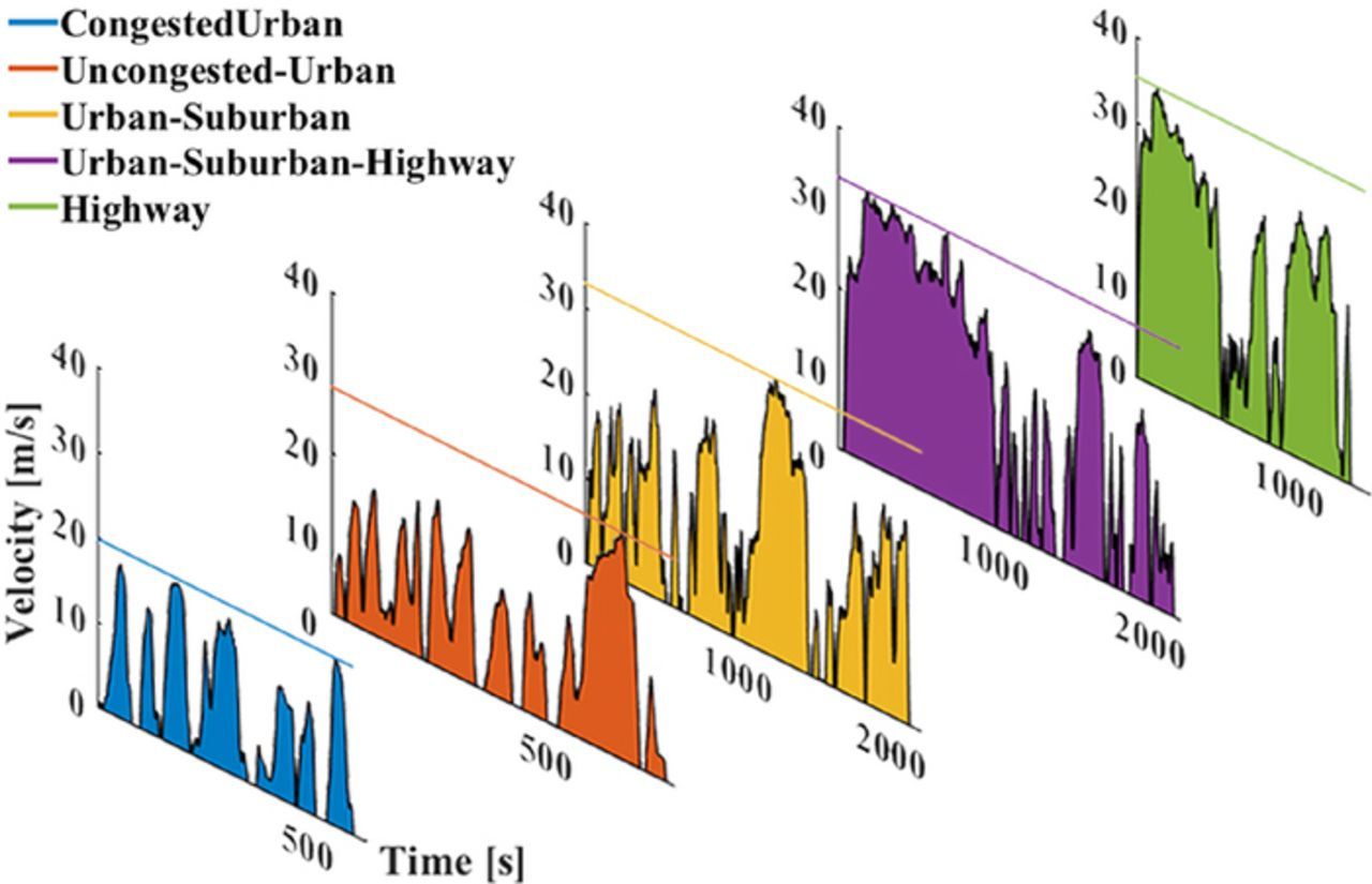
Figure 1. Representative set of drive cycles for five different use-cases: congested-urban (CU), uncongested-urban (UU), urban-suburban (US), urban-suburban-highway (USH) and highway (HW). The average velocities for these cases are 9.41, 12.42, 15.77, 21.27, and 22.33 m/s respectively. The load profiles for each of the cases are generated using the dynamic vehicle model and the battery pack is sized to meet the energy demands for each of the drive cycle.
Table III. Estimated Wh/mile, and pack specifications for base case.
| Drive Cycle/Chemistry (Wh/mile) | LMO | LFP | NCA | NMC |
|---|---|---|---|---|
| CU | 438.94 | 431.92 | 395.45 | 405.39 |
| UU | 540.12 | 531.16 | 484.67 | 497.30 |
| US | 517.69 | 511.55 | 478.98 | 487.96 |
| USH | 645.39 | 639.03 | 604.78 | 614.29 |
| HW | 636.40 | 630.52 | 598.73 | 607.58 |
| USH, Ei (kWh) | 129.76 | 128.48 | 121.593 | 123.51 |
| USH, EP (kWh) | 162.20 | 160.60 | 151.99 | 154.38 |
| USH, EP /WP (Wh/kg) | 69.60 | 72.75 | 98.57 | 89.36 |
| USH, PTC | 0.53 | 0.55 | 0.4 | 0.43 |
We can see the metrics for the battery pack as estimated by the framework for the base case, comparing the ncells, WP, EP, and the energy consumption in Fig. 2. Due to the lower number of cells required, and lower pack weight, NCA has the lowest required pack energy, while LFP has the highest. LMO and LFP also result in systems with a PTC over 0.5 (Table III), which exceeds the technical feasibility limit. These results confirm the need for higher specific energy in order to achieve high-performance LCVs. NCA and NMC seem to be the most suitable, with NCA performing marginally better than NMC in each of the metrics (10% higher specific energy, and 7% lower PTC for the base case) resulting in a 10 Wh/mile lower energy consumption. The comparative analysis reveals that the use of low specific energy chemistries like LFP and LMO is impractical for LCV applications. To conduct cycling analysis, we pick the system with the NCA-based battery pack which has the lowest energy demand of 121 kWh for the base case, with a required pack size of ∼152 kWh. The estimates for other chemistries can be found in Table III.
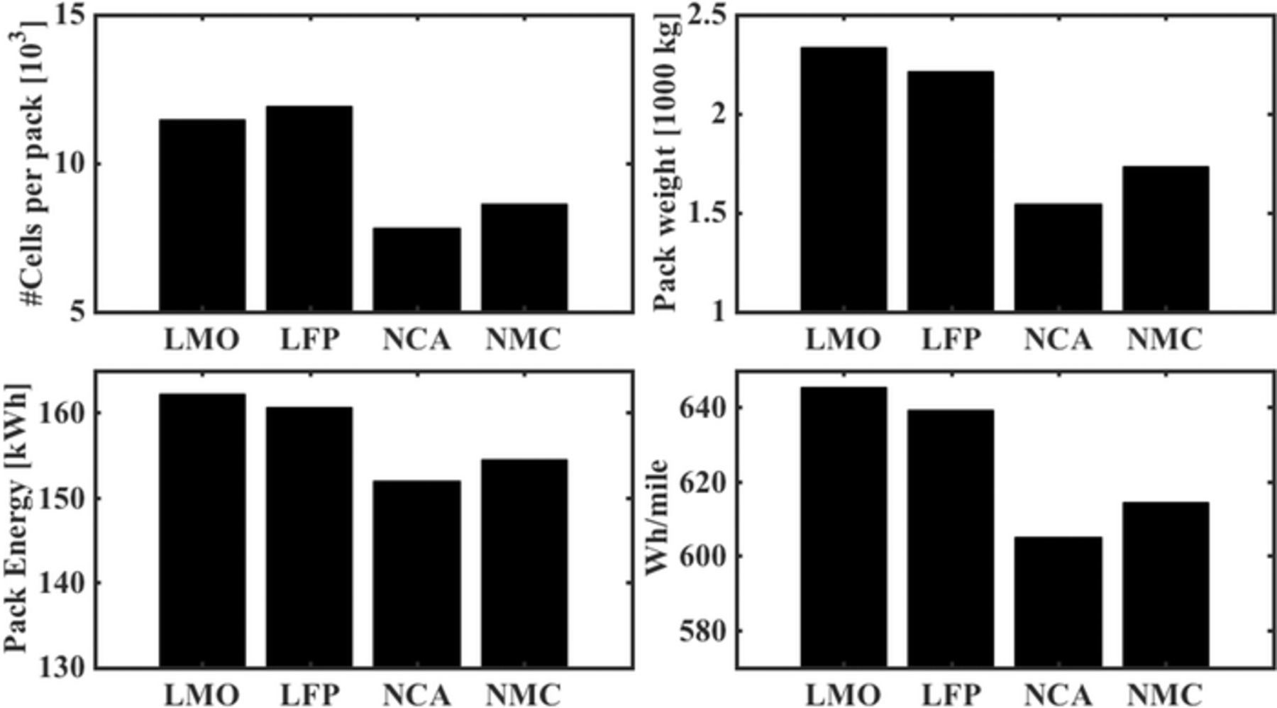
Figure 2. Comparison of estimates for battery pack metrics for the base case of electrifying a Ford F-150. For high specific energy chemistries like NCA and NMC, the number of cells is much lower than the number of cells for LFP and LMO, and the difference in the resultant pack weight causes a reduction in required pack energy. The pack energy for the chemistries are 162.2, 160.60, 151.99, and 154.38 kWh for LMO, LFP, NCA, and NMC respectively, and the corresponding energy consumption is 645.39, 639.03, 598.73, and 607.58 Wh/mile.
Aging performance analysis
Aging performance analysis conducted for the base case scenario for all the drive cycles, at a fixed ambient temperature is shown in Fig. 3a, where we see the change in the State-of-Health (SoH) of the pack, which is the percentage of initial capacity left after completing a fixed number of cycles. The NCA based battery pack was used for this analysis, sized at 152 kWh or 421.2 Ah, in a 100S78P configuration with a nominal voltage of ∼365 V. On examining Table III and Fig. 3a together, we find that the Congested-Urban case, the least energy intensive drive cycle, is the most detrimental to the SoH of the pack. A lower average velocity of the CU case indicates that the vehicle would cumulatively take a longer time to complete the same number of 200-mile trips (cycles), resulting in the battery pack being engaged for a much longer duration thereby causing higher degradation. Within the set of drive cycles CU, UU, USH, and HW, a lower average velocity seems to result in greater damage to the pack. However, it is observed that the Urban-Suburban (US) drive cycle does not fit this generalization when compared to the USH drive cycle, since the US case has an intermediate average velocity of 15.77 m/s compared to 9.41, 12.42, 21.27, 22.33 for CU, UU, USH, and HW respectively which does not increase the time required for traveling 200,000-miles or the energy consumption for the same. A combination of these factors causes the pack degradation in the US case to be comparable to the USH case. From these results, we can see that for a fixed ambient temperature, if two vehicles travel at significantly different average velocities, for the same distance traveled, we would see a lower SoH for the vehicle with the lower average velocity. This goes to show that miles driven or energy consumption alone might not be accurate metrics to study battery health, and there is a need for a better metric which couples the miles driven and the cumulative time of battery pack usage.
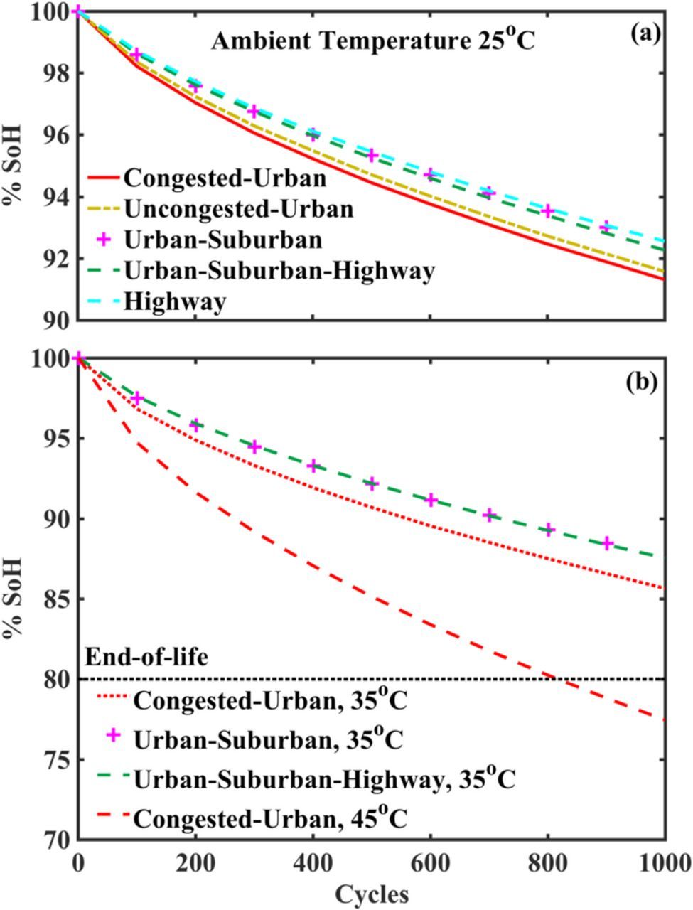
Figure 3. Results of the aging performance analysis to study the battery pack degradation, based on simulations on AutoLion-ST of an NCA-based battery pack for a range of 200 miles/cycle for the base case. (a) Degradation for different use-profiles at a fixed ambient temperature. For the same distance traveled, the CU case is the most detrimental to SoH, followed by UU, USH, US, and HW. The simulations suggest that lower average velocities result in higher degradation since the battery pack is engaged for a longer duration of time for the same distance. (b) Battery pack degradation at higher temperatures of 35°C and 45°C for selected use cases. We observe significantly lower SoH at higher temperatures for the same cycle count. At 45°C the pack reaches its end-of-life much earlier than 1000 cycles or 200,000 miles.
Fig. 3a also tells us that the total projected miles covered over the lifetime of the battery pack is much higher than 200,000 miles since the SoH is more than 90% after 1000 cycles. Changes in ambient temperature would affect this since higher temperatures are known to affect SoH drastically,71 this can be seen in Fig. 3b which shows the change in SoH at an ambient temperature of 35oC for a set of drive cycles, and at 45oC for the CU case where the end of life is reached at 800 cycles or 160,000 miles. In the overall analysis, the cycle life observed is acceptable for electric LCVs since studies72 suggest that electric vehicles are competitive when they are driven over 180,000 miles, with a vehicle age of ∼ 15 years. It should be noted that a similar analysis for longer range or a different payload capacity would significantly change the estimated cycle life.
Cost estimation
The cost estimation process described in Cost estimation section, is followed to analyze the base case battery packs. The results expressed in ($/pack) and ($/cell) values shown in Fig. 4. NCA has the lowest cost per pack, in spite of having the highest cost per cell. As seen in Fig. 2, the number of NCA cells required to assemble a pack is around 7800 cells, compared to 8600, 11500, and 11800, for NMC, LMO, LFP respectively. And owing to the high specific energy of NCA, the required pack energy is also lower. These two factors together reduce the overall cost of the NCA-based battery pack. Within the range of chemistries considered here, it is evident that specific energy of the battery pack can lead to reductions in pack size and hence the pack-level cost. In terms of commercial viability, NCA and NMC seem to be placed at a better position compared to LMO and LFP. The resultant pack-level mean-cost per unit energy ($/kWh) of these chemistries was 280 for LMO, 257 for LFP, 224 for NCA, and 241 for NMC. Studies73 on prismatic cells estimate the cell cost ($/kWh) to be slightly over 200 for LMO, NCA, and NMC, and over 280 for LFP. Another study32 reports cell costs of 290 $/kWh for LMO, 310 for LFP, 260 for NCA, and 250 for NMC, for slightly different electrode design parameters with cathode thickness of 80 μm. The difference between the estimates could be due to the difference in thickness of the electrode coating considered or, in the context of the latter study due to different electrode design parameters like material weight fractions and porosity.
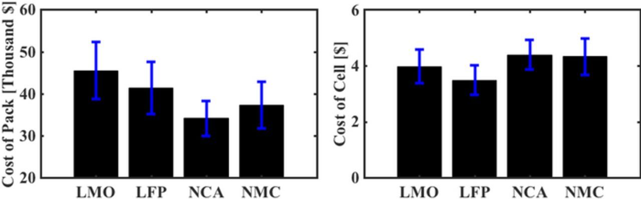
Figure 4. Cost estimates based on BatPaC for single cells and the pack for the base case. NCA has the highest cost per cell but results in a pack with the lowest cost. LMO and LFP have much lower cell cost but much higher pack costs, with LFP being the highest. The pack-level costs are primarily driven by the specific energy whereas the cell costs depend on the constituent materials used.
Trade-offs between parameters
Now we tackle the key question of what trade-off exists between the various vehicle design parameters and how they might influence near-term and longer-term electric LCVs. In order to address this, we have carried out a detailed analysis, based on possible changes in vehicle design parameters (Table V). We consider two of these parameters at a time, within a bivariate analysis setup, and study the pack cost and PTC as functions of the two chosen parameters, while the remaining are fixed at the base case values. The changes in pack cost and PTC observed are a result of the changes in pack energy and pack weight requirements obtained from the estimation framework. Each of the following figures can be examined using a cross-hair approach where we fix the cross-hair at certain values for the two parameters considered and we examine the resultant pack cost and PTC for different chemistries.
Table V. Variation in parameters for trade-off analysis.
| Parameter | Variation |
|---|---|
| WV (kg) | [1150,2300] |
| WL (kg) | [500,2000] |
| Cd | [0.2,0.4] |
| Crr | [0.0045,0.0075] |
| Range (mi) | [200,500] |
| ρ (kg/m3) | 1.17 |
| A (m2) | 5.5 |
| Drive Cycle | USH |
Fig. 5 sheds light on the pack cost (Fig. 5a) and PTC (Fig. 5b) as functions of range and the drag coefficient of the vehicle, Cd. Fig. 5a shows that, for the base case range of 200 miles, a Cd reduction of 0.2 changes the cost by $10,000 for NCA and NMC packs, and about $15,000 for LFP. On comparing the cost of a pack needed for 200-miles to that of 500-miles, at a Cd of 0.4, we find that LFP-based systems see an increase of ∼$90,000, and LMO of $70,000, as compared to ∼$60,000 for NMC and ∼$50,000 for NCA-based systems. Switching to the technical implications of this, in Fig. 5b, we see that the pack weight for LMO and LFP systems remains extremely high, and a range of over 300 miles is unattainable at low Cd's as well. At a Cd of 0.2, a range of over 350-miles would be technically feasible with NCA and NMC systems. With LMO and LFP systems, at a threshold PTC of 0.5, the maximum technically feasible range is 300-miles which is achieved at a Cd of 0.2.
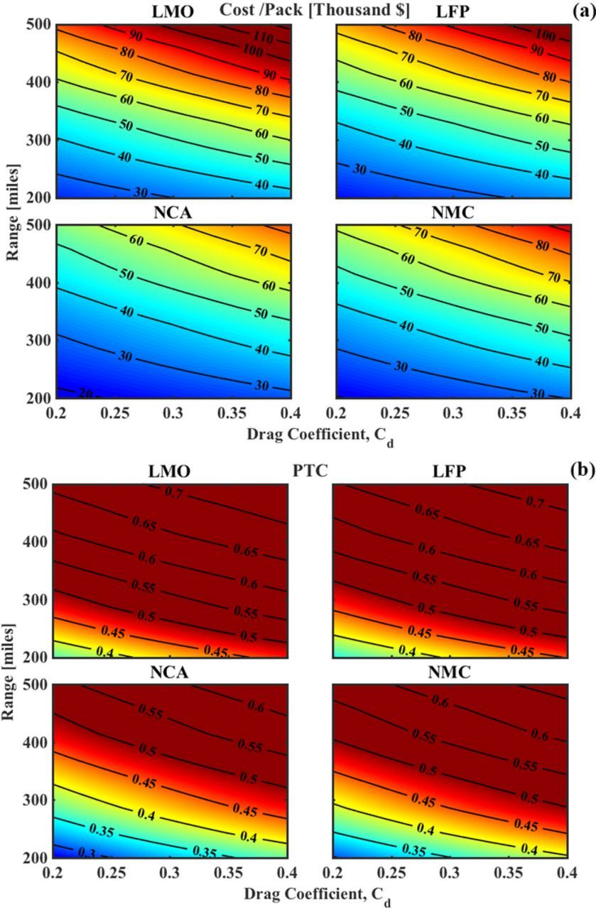
Figure 5. Estimated cost of the battery pack and PTC as a function of range and Cd at a fixed payload capacity of 1000 kg and vehicle weight of 2000 kg. (a) For a fixed cost, we observe a trade-off between range and Cd which implies that a reduction in Cd enables a longer range. The base case corresponds to an approx. cost of $30,000 for NCA and $40,000 for LMO. (b) Variations in the PTC of the vehicle, where a PTC of over 0.5 indicates the threshold after which the vehicle will not be an overall efficient system. A Cd of 0.2 enables a range of over 400-miles for NCA and NMC, and at this point, LMO and LFP would also be suitable for a lower 250-mile range.
If we hold the Cd fixed at 0.4 and take up the payload capacity as a parameter, we obtain Fig. 6, where we see cost and PTC as functions of range and payload capacity. Fig. 6a shows that the reduction in cost seen by changing the payload capacity from 2000 kg to 500 kg is around $5,000 for LFP and LMO systems while it is close to $2,000 for NCA and NMC. Clearly, for systems designed with high specific energy battery packs, a reduction in payload capacity does not change the cost of pack significantly. Fig. 6b shows that, at a fixed range, the PTC of NCA and NMC systems changes by about 0.05, for a change in payload of 1500 kg. LMO and LFP-based systems are unlikely to support any significant payload since PTC is over 0.5 even at small payloads.
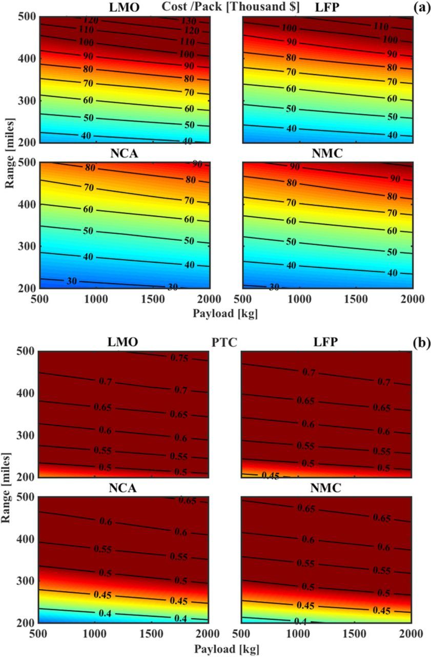
Figure 6. Estimated cost and PTC seen as functions of range and payload capacity, at a fixed Cd of 0.4 and vehicle weight of 2000 kg. (a) Cost reduction is minimal for a decrease in payload capacity. The cost LFP and LMO is very sensitive to an increase in range, due to their low specific energy, as compared to NCA and NMC. (b) A reduction in payload capacity of 1500 kg provides an approx. 10-mile increase in range for NCA and NMC packs for the same PTC. The LFP and LMO packs always remain above the threshold of 0.5 for a range of over 250 mile.
Given the challenges in pack cost reduction through significant re-design required to decrease drag coefficient to about 0.2–0.3, a reduction in vehicle weight could become crucial to reducing the energy consumption and required pack energy and thereby a reduction in pack weight. We look at trade-offs considering the range and vehicle weight as parameters in Fig. 7. Examining Fig. 7a first, we see that reducing the vehicle weight would reduce pack size requirements and thereby reduce the pack cost, while the magnitude of cost reduction is comparable to that seen in Fig. 6a since both the vehicle weight and payload capacity affect the energy demands in the same manner. Although it should be noted that the vehicle weight affects the curb weight which is constant throughout the lifetime of the vehicle, whereas, payload capacity is a parameter the vehicle is designed for and does not necessarily remain the same. This fact plays into the changes in PTC, seen in Fig. 6b, where a lower vehicle weight for a fixed range results in higher PTC's. These results show the limitation of using PTC alone as a metric for technical feasibility, specifically with parameters like the vehicle weight, since a lower PTC achieved through an increase in vehicle weight would also result in higher pack energy requirement, a higher energy consumption, and a higher pack cost as seen in the Fig. 7a. The effect of increasing the vehicle weight on the energy consumption and range capability of the electric vehicle has been noted in other studies.25
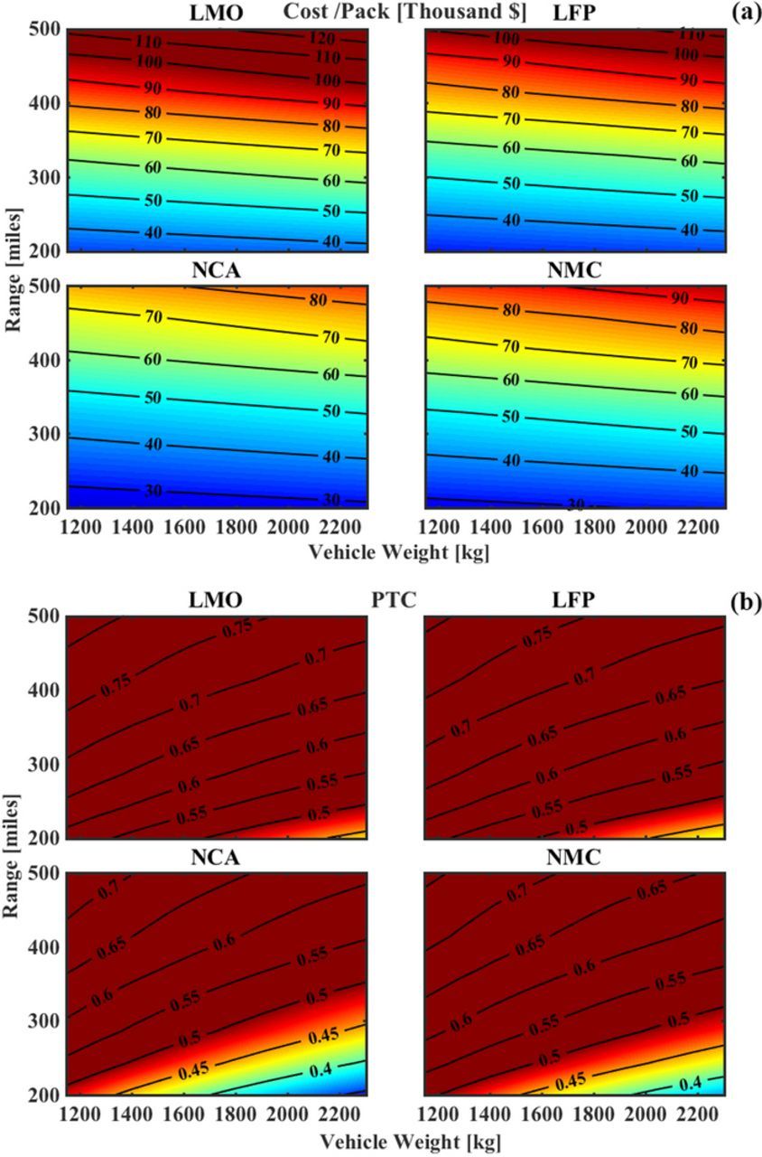
Figure 7. Cost and PTC as a function of range and vehicle weight at a fixed added load of 1000 kg and Cd of 0.4. (a) The cost shows minimal change with the vehicle weight, and the range determines the cost of the pack. (b) For any given vehicle weight, LFP and LMO systems are above the threshold on 0.5, and reducing the weight might limit the range of NCA and NMC systems if we adhere to the PTC cap of 0.5.
Finally, Fig. 8 shows cost and PTC studied as functions of vehicle weight and Cd, where we observe a few more interesting results. We see that the cost of the pack in (8a) shows a higher sensitivity to changes in Cd than to changes in the vehicle weight, which implies that the aerodynamic losses form a significant part of the energy consumption since the cost of the pack is directly related to the required pack energy. As explained previously, examining PTC as a metric for technical feasibility when vehicle weight is involved does not provide straightforward results. A conclusion similar to Fig. 7b can be seen in Fig. 8b, where a lower PTC is achieved with higher vehicle weight, but the pack cost increases due to increased energy consumption. Another interesting observation is that at low vehicle weights, the amount of change in PTC achieved by halving the Cd is much higher than 0.1 while it is much lower than 0.1 at high vehicle weights. This is due to the compound effect of lowering the vehicle weight which has an effect on the pack weight as well due to reduced energy consumption at lower vehicle weights. The effect of changing the vehicle weight on the PTC is similar for all examined chemistries, as seen in (Fig. 8b).
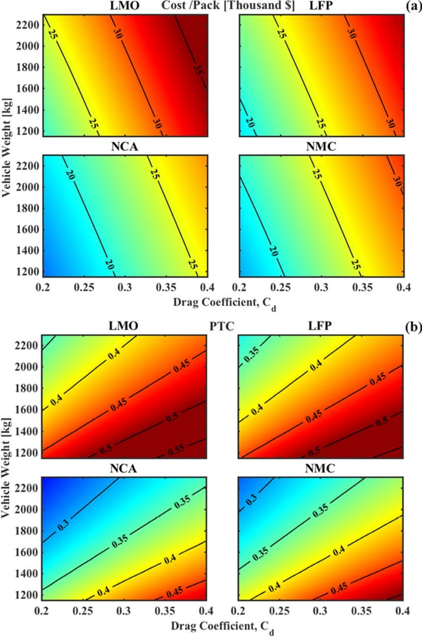
Figure 8. Cost and PTC as functions of vehicle design parameters of vehicle weight and Cd, at a fixed range of 200-miles and a payload of 1000 kg. (a) A reduction in Cd and weight both cause a decrese in cost due to lower pack size requirements. For a system based on NCA, a Cd reduction of 0.05 has the same effect is reducing the vehicle weight by 1000 kg. (b) A reduction in Cd decreases the PTC but a reduction in the vehicle weight has the opposite effect. While the Cd should be as low as possible, reduction in vehicle weight should be carried out after considering its effect on PTC.
The trade-offs for changes in the rolling resistance, Crr were also studied, and it was found that a lower Crr naturally resulted in lower pack size requirements and hence lower costs and PTC, but the magnitude of improvement for both PTC and cost was considerably small. In all the trade-offs studied here, the changes in the pack-level cost and PTC brought about by increasing the driving range is the most drastic, followed by the Cd, while vehicle weight, added load, and Crr result in marginal changes. Attempting to reduce the PTC should be performed such that the other metrics like the energy consumption or cost do not increase. A vehicle design effort undertaken for any fully electric LCV should take these effects into consideration in order to select a suitable chemistry for a set of specified performance parameters. Our analysis suggests that a first-principles based vehicle re-design such as that carried out for the Model S by Tesla Inc. would be essential to develop a cost-competitive electric LCV.
Beyond Li-ion systems
Our analysis suggests that energy density plays a crucial role in determining the sizing and cost of the battery pack. In this part of the study, we intend to quantify the potential improvements that could be obtained at a pack-level with beyond Li-ion systems. All these systems are assumed to be built with a target cost of 150 $/kWh based on estimates by other studies.26 The specific energy values used in our analysis are practical pack-level values, based on estimates from prior work,6,26,74 where we use current target and potential specific energies of [200,300] Wh/kg for future Li-ion batteries, and [350,600] and [600,1000] Wh/kg for Li-S and Li-air systems respectively. We examine the impact of specific energy on cost, PTC, and energy consumption, for different drag coefficients and driving range. The other parameters are fixed at the base case scenario, (Table I). With a cost of 150 $/kWh we observe that the cost of the base case battery pack drops well below $30,000 for current Li-ion batteries. In Fig. 9a, at a fixed Cd, we observe improvements in terms of cost reduction of the order of about $2,000 with future Li-ion and Li-S systems through the increase in specific energy to about 350 Wh/kg. The PTC at this specific energy is reduced from 0.4 of current systems to a value as low as 0.15, or in other words, the weight of the battery pack is only 15% of the total vehicle weight, thereby implying that the system efficiency, as well as the wells-to-wheels efficiency, is significantly higher. The energy consumption per mile also reduces with increasing specific energy as seen in Fig. 9c. For specific energies greater than 350 Wh/kg, the improvements obtained by increasing specific energy in terms of cost and energy consumption saturate out. For a fixed Cd, the energy consumption of a Li-S system of 350 Wh/kg is only marginally higher than a Li-air system with twice the specific energy. The PTC for the Li-air system is reduced by about 0.05, Fig. 9b, while both systems would cost approximately the same, as seen in Fig. 9a.
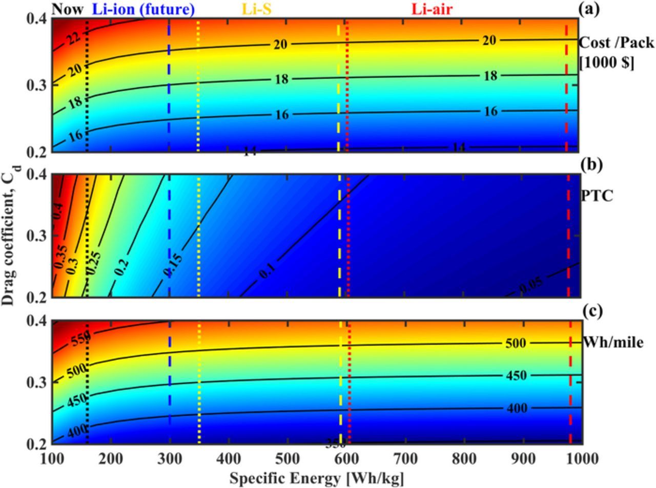
Figure 9. Examination of future and beyond Li-ion systems for improvements in (a) Cost, (b) PTC, and (c) energy consumption for a fixed range of 200-miles and a cost of 150 $/kWh across chemistries. We see an improvement in the system level cost for an increase in pack specific energy up to 350 Wh/kg which signifies the advent of future Li-ion batteries and Li-S systems. The PTC at this specific energy is around a value of 0.15. Beyond this, the degree of improvement seen for the same increase in specific energy is minimal since the pack weight does not remain a significant parameter for energy consumption. A similar trend is seen with the energy consumption of the vehicle as well (Wh/mile).
With the perspective of accelerating the electrification of the transportation sector in the LCV segment, once the specific energy improves such that the PTC of the system is about 0.15, the focus will have to shift toward vehicle design and improvements on battery manufacturing process, since system-level gains will be minimal. This calls for a need to pay attention to the materials used in fabricating battery systems of the future. The changes in system-level cost and PTC studied for increasing values of driving range can be seen in Fig. 10, where we observe similar trends of a level off that occurs after a certain specific energy. While higher specific energies would enable longer range with similar battery pack metrics, the improvements seen in driving range with increasing specific energy saturate beyond a specific energy of 350 Wh/kg. Based on Figs. 9 and 10, for the near future, if we assume a cost cap of approx. $35,000 per pack (with $150/kWh), with a Cd of 0.4, we can achieve a range of 300 miles with a 350 Wh/kg battery pack with a PTC of under 0.3 and decreasing the Cd would extend the range further. If we assume no cost cap, a practical specific energy of close to 200 Wh/kg, with advanced Li-ion batteries and Li-S systems, would enable a technically feasible system with a driving range of 500-miles and a PTC of under 0.5, but the pack would cost over $60,000. To re-iterate these targets in terms of cell-level specific energies, 200 Wh/kg translates to a 440 Wh/kg cell, and 350 Wh/kg translates to about 770 Wh/kg, assuming an fburden factor of 0.45.
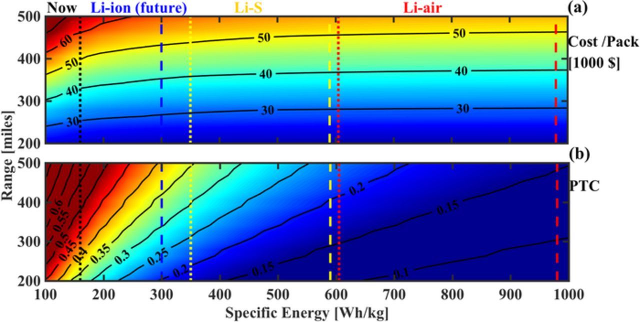
Figure 10. Future and beyond Li-ion batteries compared based on (a) Cost and (b) PTC, for enabling a greater driving range and trade-offs that occur are examined for a fixed Cd. Clearly, a higher specific energy enables longer range for the same cost and PTC, but these improvements begin to plateau for specific energies higher than that of Li-S. With current Li-ion specific energies, for a pack specific energy of 160 Wh/kg, a 350-mile range would reach the PTC cap of 0.5.
Each of these beyond Li-ion systems currently entail their own challenges to assemble practical systems.5,75,76 For example, future Li-ion systems with practical specific energies of greater than 200 Wh/kg would be achieved via high capacity anodes based on Li metal which has issues with dendrite growth and cycling26 or with Si which currently suffers from volumetric expansion and rapid degradation.77 The Li-S system suffers from challenges with polysulphide formation-dissolution, volumetric changes at the cathode, and stability of the electrolyte, and current targets of Li-S systems are still only comparable to Li-ion systems with high capacity anodes.7 The Li-air battery has issues with specific power,75 rechargeability,5 and other challenges with finding stable electrolyte and cathode materials,75 and currently the target is to achieve a specific energy of 600 Wh/kg,26 the value which was used in our trade-off analysis in this study. Researchers are also attempting to develop other metal-air batteries such as Na-air,80,81 where the state of understanding and research is at a very early stage,5 and hence such systems have not been included in this study.
Conclusions
The current pack-level specific energy of Li-ion batteries will only provide a range of (200–250) miles under technically feasible limits for current LCV designs similar to that of a Ford F-150 although the cost of the battery pack is prohibitively high. We can reduce the cost at a system level through a vehicle re-design by reducing the drag through lowering of the drag coefficient to about 0.2–0.3, and consequently reduce the pack size requirements. While these could enable initial market penetration, there is a need for further increasing the driving range and performance for mass-electrification. Future Li-ion systems and beyond Li-ion systems need to be exploited in order to enable greater range with higher performance (and lower PTC). We find that the improvements begin to level off due to the low values of PTC leading to no system-level cost reductions with increasing specific energy beyond 350 Wh/kg. Keeping the current Li-ion systems in mind, in current time scales, we require a minimum pack-level specific energy of over 200 Wh/kg or 400 Wh/kg at the cell-level. In the near future, for long range electric LCVs, the target should be to reach a specific energy of about 350 Wh/kg, beyond which greater gains can be obtained only through a vehicle re-design. Once the target of 350 Wh/kg at a pack-level is reached, long range of over 400-miles for LCVs would become technically feasible, and with significant cost reduction, we could have a mass market high-performance Light Commercial Vehicle.
Acknowledgments
The authors acknowledge Dr. Zifan Liu and Dr. Andrej Ivanco at the Clemson University International Center for Automotive Research (CUICAR), for providing the extremely useful drive cycle data for LCVs/ pickup trucks.