Abstract
Herein, we present the synthesis and characterization of negative (a hard carbon/carbon black composite) and positive (K0.3MnO2) active materials for K-ion batteries as well as their combination in a non-aqueous K-ion cell. The hard carbon/carbon black composite can deliver up to 200 mAh g−1 while the layered birnessite K0.3MnO2 delivers up to 136 mAh g−1. The K-ion cell exhibits an interesting and encouraging cycling performance for 100 cycles. These exciting new insights demonstrate the potential of K-ion batteries, which are worth to be further investigated in greater detail.
Export citation and abstract BibTeX RIS

This is an open access article distributed under the terms of the Creative Commons Attribution 4.0 License (CC BY, http://creativecommons.org/licenses/by/4.0/), which permits unrestricted reuse of the work in any medium, provided the original work is properly cited.
Since the 1970s, lithium-, sodium- and potassium-based rechargeable battery technologies have been studied in parallel. However, the commercialization of the first lithium-ion battery (LIB) in 1991 shifted the focus of the research community solely toward this battery technology. Despite the success of LIBs, recent concerns about, e.g., the availability of lithium raw materials have led to an increased interest to revisit alternative secondary battery technologies. Attention shifted back to Na-ion batteries (NIBs) due to the high abundance and low cost of sodium minerals and the feasible replacement of the copper anode current collector with aluminum, which leads to a cheaper battery. These advantages are considerable since NIBs show comparable electrochemical performance to LIBs.1
Interestingly, K-ion batteries (KIBs) were not considered in recent years, despite the fact that they exhibit, in principle, similar advantages: Like sodium, potassium does not alloy with aluminum at low potentials.2 Potassium raw materials, like K2CO3, are of lower cost (1000 USD t−1 for K2CO3 and 6500 USD t−1 for Li2CO3 (≥99%)), abundant and more homogenously distributed than lithium.3 A significant advantage of KIBs, as compared to NIBs, is the lower standard potential of K+/K vs. the standard hydrogen electrode (SHE). The standard potentials are reported as −2.71 V for Na+/Na, −2.94 V for K+/K and −3.04 V for Li+/Li. However, these values are only valid for measurements vs. SHE and vary in dependence of the solvent as the redox couple K+/K, in fact, shows a lower potential in PC compared to Li+/Li (−2.88 vs. −2.79 V, respectively).4 Consequently, KIBs could, in theory, deliver similar cell voltages to LIBs and higher than NIBs. In addition, higher transport numbers and mobility of K+ ions could be possible in non-aqueous electrolytes due to the lower charge density of K+ vs. both, Li+ and Na+.5 However, the larger Shannon's ionic radius and higher atomic weight of potassium (1.40 Å and 39.098 g mol−1 for K+) vs. lithium (0.76 Å and 6.941 g mol−1) and sodium (1.00 Å and 22.990 g mol−1) result in decreased gravimetric and volumetric energy.5,6 The high reactivity of K metal also raises serious safety concerns and is probably one of the major reasons why KIBs have not yet been investigated in greater detail. Nevertheless, the interesting properties of KIBs, which are between those of LIBs and NIBs, certainly deserve a more detailed investigation.
The first seminal reports on K ion-based layered compounds (KxTiS2, KxCoO2) were published between 1969 and 1975.7,8 K compounds were then continuously investigated in the following decades, mostly focusing on their ability to de-intercalate K+, followed by ion exchange with Li+ in order to obtain the analogous Li+-containing compounds.9,10 Aqueous systems, comprising Prussian blue (KFeIIIFeII(CN)6) or other hexacyanoferrates as active material, have been studied intensively since the 1980s.11–15 In addition, layered KxMnO2 · (0.3 ≤ y ≤ 0.6) H2O has been reported as cathode material in aqueous K-ion capacitors.16,17
With respect to non-aqueous electrolytes, A. Eftekhari studied the use of Prussian blue as active material in combination with potassium metal using 1 M KBF4 in EC:EMC (30:70 wt.) electrolyte in 2004.18 From 2012 on, other studies reported the performance of different active materials (amorphous FePO4, FeSO4F, carbon nanofibers, organic electrode) in potassium-metal cells and with different organic electrolytes.19–22 The use of K metal is not likely to be accepted for a practical application due to severe safety concerns, which are undoubtedly higher than for Li or even Na metal. For this reason, interest lies in finding suitable anode materials which can be applicable in K-ion full cells, thus reducing the risks associated with K metal. Recently, soft carbon, hard carbon (HC) and graphite were evaluated as anode materials in KIBs.5,23,24 Compared to soft carbon, graphite exhibits a more pronounced capacity fade and lower rate capability, but both deliver high capacities of about 260 mAh g−1.23 The use of HC is interesting as the capacity is mostly delivered above 0.1 V, which reduces the risk of K-metal plating.24 Komaba et al. demonstrated that in EC:DEC organic electrolytes KFSI [potassium bis(fluorosulfonyl)imide] is the most appropriate conductive salt in comparison with KClO4 and KPF6 due to its higher solubility.5
Only few reports on positive and negative electrode materials for KIBs exist and, to the best of our knowledge, a conventional non-aqueous KIB (full cell) has not been demonstrated yet. Thus far, only one report dealing with an unconventional K-ion oxygen cell, employing an oxygen cathode, is available, albeit with limited cycling.25 All of the other cell tests published to date using non-aqueous electrolytes, both with respect to potential anode and cathode materials, were conducted using K metal as a counter electrode and are therefore considered to be either a K-metal cell or a K half cell. This encouraged us to develop a conventional KIB based on starch-derived HC and layered birnessite (K0.3MnO2) as the negative and positive electrode material, respectively, with 1.5 M KFSI in EC:DMC (1:1 vol) as electrolyte.
Experimental
Synthesis of rice starch-derived hard carbon
Hard carbon (HC) was synthesized by thermal decomposition of starch powder from rice (Sigma-Aldrich). First, starch was preheated in a muffle furnace in air at 503 K for 4 h (heating rate of 1 K min−1), resulting in black grains (yield of 28%). After grinding, the preannealed material (a sample of about 4 g) was finally heated in a tube furnace under argon atmosphere, following the procedure of Stevens et al.26 In detail, an argon flux of 105 cm3 min−1 was used to prevent decomposition-products from further reaction with the material.27 A heating rate of 1 K min−1 was applied until 1373 K, which was held for 1 h. The material was furnace-cooled to room temperature under the argon flow. Finally, a black powder (yield of 50% of the preheated precursor, about 13% total yield) was obtained and used without further purification.
Synthesis of K0.3MnO2
Layered potassium manganese oxide was obtained via annealing of KMnO4 (Sigma-Aldrich, ≥99%), following the procedure of Kim et al. and Gaillot et al.28,29 In detail, grinded KMnO4 was dispersed in a thin film of 33 mg cm−2 in an alumina crucible, heated in an ambient air atmosphere with 1 K min−1 to 1273 K and held for 5 h. The preannealed material was cooled to ambient temperature with a controlled rate of 1 K min−1. The preannealed material was then carefully rinsed with desalinated water to remove permanganate residues and other impurities. The rinsed material was dried in air at 363 K for 10 h, sieved to a particle size of less than 45 μm and then used without further purification.
Material characterization
Structure and morphology of the active materials was conducted using X-ray diffraction (XRD, Bruker D8 Advance diffractometer with a CuKα radiation (λ = 0.154 nm)) and scanning electron microscopy (SEM, Zeiss Auriga, samples sputtered with 4 nm of platinum). The Brunauer-Emmett-Teller (BET) surface area was investigated by nitrogen adsorption measurements, using an ASAP 2020 (Accelerated Surface Area and Porosimetry Analyzer, Micrometrics). Raman spectra were recorded using a confocal InVia Raman microspectrometer with a 633 nm laser (Renishaw). The final Raman spectrum is the average of three 10-second accumulations. Thermogravimetric analysis (TGA) was carried out with a Discovery Thermogravimetric Analyzer (TA Instruments) in a nitrogen atmosphere and in a sealed aluminum pan which was filled in an Ar-filled glove box.
Electrode preparation
Electrodes were processed by mixing the active material with a polyvinylidene difluoride binder (PVdF, 10 wt% solution in N-Methyl-2-pyrrolidone (NMP), 6020 Solef, Arkema Group) and conductive carbon black (CB) (Super C65, IMERYS) in NMP via ball milling for 3 h. The slurries were casted on aluminum foil (20 μm). The coated foils were pre-dried at 333 K in air for 24 h. Round disk electrodes (Ø = 12 mm) were cut, dried at 393 K under vacuum for 24 h, pressed, dried again for 6 h at 393 K under vacuum and, finally, stored under inert atmosphere in an Ar-filled glove box. The slurry composition depended on the active material. For K0.3MnO2, the final electrode composition was 85 wt% K0.3MnO2, 10 wt% carbon black and 5 wt% binder. The average active material mass loading for potassium metal half-cell tests for the cathode was about 2.1 mg cm−2. For the composite electrodes, the final electrode composition was 70 wt% HC, 20 wt% CB and 10 wt% binder. For the pure HC and pure CB electrodes, the composition was 90 wt% active material and 10 wt% binder. The average active material mass loading for potassium metal half-cell tests was about 2.4 mg cm−2 for the HC and 1.0 mg cm−2 for the CB and 1.3 mg cm−2 for the composite.
Electrochemical characterization
Galvanostatic cycling tests were carried out on a Maccor battery tester 4300 and cyclic voltammetry (CV) on a VMP3 Potentiostat (Biologic). All electrochemical tests were carried out in climatic chambers at a temperature of 293 ± 1 K. The electrolyte preparation and cell assembly were carried out in a glove box (MBraun) with an oxygen and water content below 0.1 ppm. 1.5 M KFSI [potassium bis(fluorosulfonyl)imide, 99.9%, Solvionic] in EC:DMC (1:1 vol. solution) [ethylene carbonate(EC,99.95%, BASF) and dimethyl carbonate (DMC, battery grade, UBE) used as received and mixed in appropriate volumetric ratios] was used as electrolyte. As comparative electrolyte, 1 M KPF6 (99.5%, Sigma-Aldrich) in EC:DMC (1:1 vol. solution) was used after removal of insoluble residues by filtration.
Electrolyte stability tests
Electrochemical stability windows were determined using a Solartron model 1287A potentiostat, controlled by Corrware software at 293 ± 1 K in three-electrode Swagelok cells by linear sweep voltammetry (LSV) at 1 mV s−1. A platinum microelectrode (embedded in PEEK; active area = 0.79 mm2) was used as working electrode and K metal as the counter and reference electrodes. LSV tests were performed by scanning the cell potential from the open circuit potential toward more cathodic or anodic potentials to determine the cathodic and anodic electrochemical stability limits. Separate cells were used for the anodic and cathodic sweeps.
Potassium-metal cells
Three-electrode Swagelok cells were assembled using the appropriate working electrode and potassium metal (99.5%, Sigma-Aldrich) as the counter and reference electrodes. Three-electrode cells were used instead of two-electrode cells to avoid the possible influence of the polarization of the potassium metal electrode upon cycling. The polarization of the Na-metal electrode in electrolytes containing ethylene carbonate has been demonstrated recently by A. Rudola et al.30 Thus, all potential values refer to the K+/K reference couple. Whatman GF/D glass fiber separators were used and drenched with 200 μL of electrolyte for the main electrode separator and 100 μL for the reference separator. The specific current of 279 mA g−1 is defined as 1C for all active materials.
HC/CB composite – K0.3MnO2 cell
Three-electrode, Swagelok cells were assembled with potassium metal as reference electrode. The active mass loading of the anode composite and K0.3MnO2 electrodes were 1.47 mg (about 1.30 mg cm−2) and 1.99 mg (about 1.76 mg cm−2), respectively. The cell balancing was based on the delivered capacity of K0.3MnO2 between 3.5 and 1.5 V vs. K+/K (≈63 mAh g−1) and the HC/CB composite between 0.1 and 1.0 V (≈160 mAh g−1) at 0.2C with consideration of the anode fading. The composite electrode was pre-activated via a sacrificial electrode at a low current of 0.02C, (5.58 mA g−1) until 0.02 V. The K-ion cell rested for 6 h prior galvanostatic cycling.
Results and Discussion
The structural characterization of both active materials is depicted in Figure 1. Layered K0.3MnO2 was synthesized via thermal decomposition of K2MnO4.28,29 ICP-OES analysis confirms a K:Mn ratio of 0.3:1.0, which is in accordance with a previous report.31 It should be noted that this material exhibits a strong tendency to intercalate water in ambient atmosphere (Figure S1 in the supporting information (SI)) which is why an additional drying step of the as-prepared material is required. X-ray diffraction and the corresponding Rietveld refinement demonstrate the successful synthesis (Figure 1a (ICSD 156080)). Layered K0.3MnO2 has a two-layer orthorhombic unit-cell (space group: Ccmm) with refined lattice parameters of a = 5.098(8) Å, b = 2.839(9) Å and c = 12.822(6) Å.31 In K0.3MnO2, the Mn atoms are octahedrally coordinated by oxygen anions while the K+-cations are located between the transition metal layers with trigonal prismatic coordination. The scanning electron micrograph (SEM) in Figure 1a proves the flake-like, micro-sized particle morphology in accordance with the layered structure.

Figure 1. X-ray diffraction pattern and scanning electron micrographs of a) dried layered K0.3MnO2 (SEM at 10kx) and b) hard carbon (SEM at 2kx).
The XRD pattern of starch-derived HC (Figure 1b) depicts the characteristic reflections of this material. The calculated interlayer distance (via Bragg equation) is about dhkl = 4.43 Å.32 Raman spectroscopy (Figure S1c) confirms the presence of the characteristic D (1350 cm−1) and G (1580 cm−1) bands (ID/IG: 3.02). SEM indicates that the particle size distribution is wide (ranging from few hundred nanometers to several micrometers) and the particle morphology is inhomogeneous. The BET surface area is about 125 m2 g−1.
After verification of the successful syntheses, the active materials were electrochemically characterized in three-electrode cells with potassium metal as the counter and reference electrodes and 1.5 M KFSI in EC:DMC (1:1 vol.) as the electrolyte. KFSI was selected since we also observed issues regarding the solubility of other K-conducting salts (KPF6 and KClO4) and, additionally, detected a lower electrochemical stability of 1 M KPF6 in the EC:DMC (1:1 vol.)-based electrolyte (Figure S1d). For all the electrochemical investigations, the current rate of 279 mA g−1 was defined as 1C.5,23,24
The performance of layered K0.3MnO2 is depicted in Figure 2. At a first glance, it is apparent that the material has the most stable cycling performance between 3.5 and 1.5 V vs. K+/K.
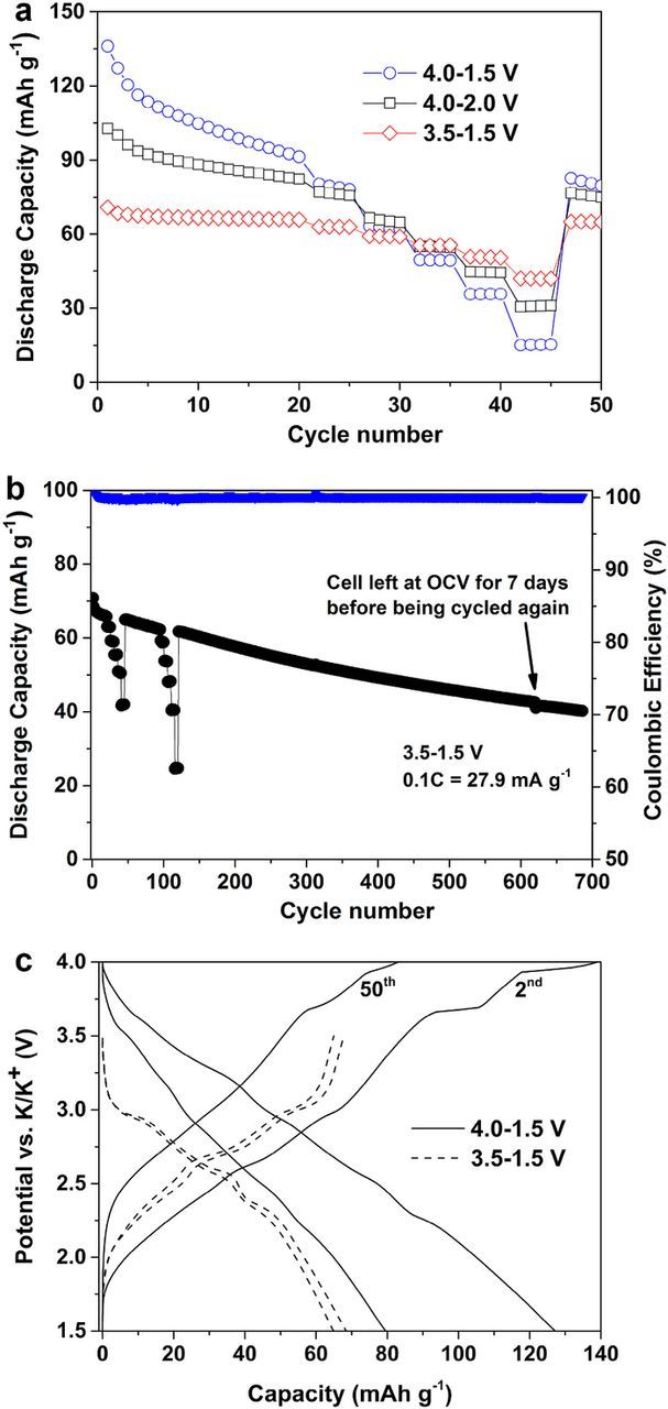
Figure 2. Electrochemical characterization of layered K0.3MnO2 with 1.5 M KFSI in EC:DMC in K-metal three electrode cells. a) Galvanostatic cycling in different potential ranges at 0.1C (27.9 mA g−1). Cycles 21–45 correspond to a C-rate test at 0.2C, 0.5C, 1C, 2C and 5C. b) Galvanostatic long-term cycling between 3.5 and 1.5 V at 0.1C. Cycles 21–45 and 96–120 correspond to C-rate tests with 5 cycles at 0.2C, 0.5C, 1C, 2C and 5C. After 620 cycles, the cell was left at open cell voltage (OCV) for 7 days before being cycled again. c) Potential profiles of the 2nd and 50th cycle at 0.1C in the voltage ranges 3.5–1.5 V and 4.0–1.5 V.
This is reflected by the capacity retention (1st–50th cycle) of about 58%, 73% and 91% for cycling between 4.0 and 1.5 V, 4.0–2.0 V and 3.5–1.5 V, respectively. The specific discharge capacity decreases in the same order from 136 mAh g−1 (0.55 eq. K+) to 100 mAh g−1 (0.39 eq. K+) to, finally, 70 mAh g-1 (0.26 eq. K+). Nevertheless, it should be highlighted that K0.3MnO2 has an encouraging cycling behavior between 3.5 and 1.5 V for 685 cycles at 0.1C (27.9 mA g−1) as depicted in Figure 2b. Even with two current rate (C-rate) tests (cycles 21–45 and 96–120), the material shows a very high capacity retention of 72% (1st–350th cycle) and a high voltage efficiency (93%, 2nd cycle). In total, the cell was cycled for 620 cycles, left at open cell voltage for 7 days and then cycled again. The interruption resulted in a minor loss of capacity and the cell was able to be run for 65 additional cycles, leading to a capacity retention of 57% (1st–685th cycle) or 68% (10th–685th cycle).
The reason for the different electrochemical performance in different potential ranges can be explained via the potential profiles in Figure 2c. During the charge process between 4.0 and 1.5 V, two plateaus are apparent at 3.7 and 3.9 V, indicating that two phase reactions occur. In fact, considering the trigonal prismatic coordination of K+ in K0.3MnO2, the (de-)potassiation mechanism could be explained in analogy to Na-based layered oxides with Na+ cations in the same coordination.33 Accordingly, the features in the potential profile could be described via a layer gliding mechanism of adjacent oxygen layers induced by the high coulombic repulsion at lower potassium contents. These processes are accompanied by large volume changes and thus partially irreversible, which explains the observed capacity fade in this potential range. Consequently, avoiding these phase transitions by lowering the upper cutoff potential to 3.5 V led to much more stable cycling. The other features in the potential profiles can, again in analogy to sodium, be explained via K+ vacancy ordering in the potassium layer as a result of the large ionic radius and related coulombic interaction of K+ cations.34,35 More detailed information regarding the evolution of potential profiles upon cycling and at increased current rates as well as cyclic voltammetry can be found in the SI (Figure S2).
The electrochemical characterization of the negative electrode is depicted in Figure 3. Although it has not been considered in any of the previous works, the carbon black used as conductive additive might be active toward K+-ion intercalation. For such reason, the cycling performance of three different electrode compositions, pure HC (90 wt% HC, 10 wt% PVdF), pure carbon black (CB, Super C65) (90 wt% CB, 10 wt% PVdF) and the composite electrode of HC and CB (70 wt% HC, 20 wt% CB,10 wt% PVdF), was evaluated. As a matter of fact, the conductive additive was capable to deliver about 170 mAh g−1 in the first cycle (i.e., higher than in NIBs36), but was affected by a substantial fading upon cycling. The pure HC electrode delivered 200 mAh g−1 at 0.1C, had a rather poor rate performance, and, even more important, poor cycling stability as evidenced by the capacity fading after the 40th cycle. Surprisingly, the HC/CB electrode, instead, offered the same initial capacity as HC, better rate performance, and stable cycling behavior with capacities of 200 mAh g−1 at 0.1C after 50 cycles and 54 mAh g−1 at 10C. The low rate capacity retention (1st vs. 50th cycles) was 73%, 81% and 97% for the CB, the HC and the composite electrode, respectively. More detailed information about the cycling performance of the electrodes can be found in the SI (Figure S3).

Figure 3. Electrochemical characterization of the HC, CB and HC/CB (ratio 70:20) negative electrodes with 1.5 M KFSI in EC:DMC in K-metal three electrode cells. a) Performance upon cycling within 0.02–2.0 V range. Cycles 11–40 correspond to the C-rate test (5 cycles at each 0.2C, 0.5C, 1C, 2C, 5C and 10C). b) Selected potential profiles recorded at 0.1C (cycle 10), 1C (cycle 28) and 10C (cycle 38) for the HC/CB composite.
Selected potential profiles of the HC composite electrode at different C-rates are shown in Figure 3b. The potential profile of the initial cycle at 0.1C and the cyclic voltammetry results are discussed in the SI (Figure S3). However, it should be noted that the first cycle coulombic efficiency (about 50%) is in agreement with previous reports.24 The potential profile recorded at the low current rate of 0.1C (10th cycle) is similar to that observed in NIBs, LIBs and in previous KIB studies.24,37 Consequently for the potassiation process, the sloping potential between 1.2 and 0.3 V vs. K+/K is mostly associated with the intercalation of K+ (100 mAh g−1) into distorted graphitic sheets while the low potential plateau between 0.3 and 0.02 V vs. K+/K mostly corresponds to micro-pore filling (100 mAh g−1). An important difference between the electrochemical behavior of HC in KIBs and NIBs is that potassiation occurs mainly above 0.1 V, decreasing the risk of potassium plating and the associated safety concerns.24
At increased current rates, the low potential plateau shifts below the lower cutoff potential upon discharge, which leads to decreased delivered capacities. Nevertheless, it should be highlighted that the composite negative electrode has a good rate capability as 54 mAh g−1 (38th cycle) are delivered at 10C (2.79 A g−1). In fact, Jian et al. found evidence for faster diffusion of K+ as compared to Na+ in HC.24
Finally, a K-ion cell was assembled (Figure 4) with layered K0.3MnO2 as positive electrode (32.0 mA g−1 based on the active cathode material) and the HC/CB composite as negative electrode (43.3 mA g−1 based on the active anode material). The voltage range was set to 3.4–0.5 V due to the reversible cycling of K0.3MnO2 between 3.5 and 1.5 V. The anode was electrochemically pre-potassiated to compensate for the irreversible capacity loss, most probably due to SEI formation in the initial cycles. The mass balancing of the K0.3MnO2 cathode to the HC/CB composite anode was set to about 1.35 and thus, the final cell was cathode limited in terms of capacity. The electrochemical pre-potassiation of the anode and the potential profile of the first cycle can be found in the SI (Figure S4).

Figure 4. Electrochemical characterization of the K-ion battery composed of K0.3MnO2-HC/CB with 1.5 M KFSI in EC:DMC as electrolyte. a) Discharge capacity and coulombic efficiency of the cell cycling between 3.4 and 0.5 V at 32.0 mA g−1cathode (43.3 mA g−1anode). Potential profiles at the 2nd and 100th cycles of b) the cell and c) the negative and positive electrodes. Since the cell is cathode limited, the capacities are based on the active mass of the cathode.
Figure 4a shows the galvanostatic cycling behavior of the cathode in the cell. At first glance, a continuous capacity fade with a coulombic efficiency of about 99% is present upon cycling. The specific discharge capacity based on the cathode is about 90 mAh g−1 in the 1st and 82 mAh g−1 in the 2nd cycle. The higher fading as compared to the K-metal half cell is due to the potential range of the cathode dropping below 1.5 V. Upon further cycling, the capacity fades to 46 mAh g−1 in cycle 100. This leads to a capacity retention of about 50% (1st–100th cycle) and 62% (5th–100th cycle), respectively. Considering that no electrolyte, electrode or cell optimization has been performed, these results are surely encouraging.
Figure 4b depicts the potential profiles of the 2nd and 100th cycles of the cell. It delivers an average output voltage of 1.9 V and exhibits a voltage efficiency of 81% (2nd cycle), which decreases to about 76% in the 100th cycle. The shortening and shifting of the potential profile can be explained by the corresponding potential profiles of the positive and negative electrode, shown in Figure 4c. Layered K0.3MnO2 has a very reversible cycling behavior shown by the almost perfect overlap of the potential profiles upon discharge. In contrast, the potential profiles of the HC/CB composite prove the negative electrode to be the origin for the observed capacity fade and decreasing energy efficiency upon cycling. This is in line with the low coulombic efficiency observed in K-metal half-cells and indicates an irreversible loss of K+ upon cycling. The negative electrode potential at the end of discharge increases from 0.93 V in the 2nd to 1.82 V in the 100th cycle. This shift causes the positive electrode potential to increase from 3.4 V in the 2nd cycle to 3.6 V in the 100th cycle at the end of charge. Further optimization of the active materials, and the anode in particular, is necessary to improve the reversibility of KIBs.
Conclusions
In summary, we successfully synthesized and characterized starch-derived HC and layered birnessite (K0.3MnO2) as active materials for K-ion batteries. The composite HC/CB electrode, as anode, has the best electrochemical performance and rate capability in K-metal cells with capacities as high as 200 mAh g−1 at 0.1C. The reversibility of the (de-)potassiation process of the K0.3MnO2 cathode was found to strongly depend on the upper cutoff potential, probably due to the occurrence of irreversible phase transitions at higher potentials. However, between 3.5 and 1.5 V vs. K+/K, a reversible cycling performance was obtained with capacities of about 65 mAh g−1 and an overall capacity retention of 57% (1st–685th cycle) or 68% (10th–685th cycle). The combination of these two materials with a non-aqueous KFSI in EC:DMC electrolyte resulted in the formulation of a non-aqueous K-ion battery which showed an encouraging electrochemical performance over 100 cycles with coulombic efficiencies higher than 99.0% and a voltage efficiency of about 81% (2nd cycle).
These results are a proof of principle and future work in this field should focus on the development of positive and negative electrode materials which have a stable electrochemical performance at high and low voltages, respectively.
Acknowledgments
The authors acknowledge J. Riegert for supporting the figure preparation and IMERYS for providing Super C65 carbon black.