Abstract
The Solid-Electrolyte-Interphase (SEI) model for non-aqueous alkali-metal batteries constitutes a paradigm change in the understanding of lithium batteries and has thus enabled the development of safer, durable, higher-power and lower-cost lithium batteries for portable and EV applications. Prior to the publication of the SEI model (1979), researchers used the Butler-Volmer equation, in which a direct electron transfer from the electrode to lithium cations in the solution is assumed. The SEI model proved that this is a mistaken concept and that, in practice, the transfer of electrons from the electrode to the solution in a lithium battery, must be prevented, since it will result in fast self-discharge of the active materials and poor battery performance. This model provides [E. Peled, in "Lithium Batteries," J.P. Gabano (ed), Academic Press, (1983), E. Peled, J. Electrochem. Soc., 126, 2047 (1979).] new equations for: electrode kinetics (io and b), anode corrosion, SEI resistivity and growth rate and irreversible capacity loss of lithium-ion batteries. This model became a cornerstone in the science and technology of lithium batteries. This paper reviews the past, present and the future of SEI batteries.
Export citation and abstract BibTeX RIS

This is an open access article distributed under the terms of the Creative Commons Attribution 4.0 License (CC BY, http://creativecommons.org/licenses/by/4.0/), which permits unrestricted reuse of the work in any medium, provided the original work is properly cited.
The Past
Prior to the publication of the SEI model (1979),1,4 researchers used the Butler-Volmer equation, in which direct electron transfer from the electrode to lithium cations in the solution is assumed. It was generally assumed that the rate-determining step (RDS) is the transfer of electrons from the metal to the cations in the solution. Researchers found that the lithium anode is covered by a passivating layer which interferes with the deposition/dissolution process of the anode. Brummer and Newman2,3 concluded that a passivating anode can offer only a limited cycle life and in order to obtain a deep-discharge high-cycle-life secondary battery, the lithium anode must be free of a passivating layer and kinetically stable with respect to the electrolyte. The SEI model proved that this is a mistaken concept and that, in practice, the transfer of electrons from the electrode to the solution in a lithium battery, except when forming a SEI, must be prevented.
The Present, Lithium-Metal and Lithium-Ion Batteries
Introduction
It is now generally accepted that the solid-electrolyte interphase (SEI) is essentially for the existence and successful operation of lithium- and sodium-battery systems, as primary and secondary power sources.4 In 1979, it was proposed by Peled,4 that this SEI model is valid for all alkali metals and alkaline earths in non-aqueous-battery systems. The layer, formed instantaneously upon contact of the metal with the solution, consists of insoluble and partially soluble reduction products of electrolyte components. The thickness of the freshly formed layer is determined by the electron-tunneling range. The layer acts as an interphase between the metal and the solution and has the properties of a solid electrolyte with high electronic resistivity. The batteries containing SEI electrodes were called SEI batteries.4
SEI is the key factor which determines the safety, power capability, morphology of lithium deposits, shelf life, and cycle life of the battery.1,5–7 To eliminate concentration polarization and to facilitate the metallic anode dissolution/deposition processes, the cation transport number should be close to unity. The SEI must be both mechanically stable and flexible. Good adhesion to the anode is important as well. As emphasized above, practical primary or secondary alkaline or alkaline-earth batteries can be constructed only if the dissolution or corrosion of the anode can be stopped. Therefore, the electrolyte must be designed to contain at least one SEI precursor that reacts rapidly with lithium (or with the alkali-metal anode) to form an insoluble solid-electrolyte interphase - the SEI. In addition, in order to create a protective SEI on alkali-metal anodes, it is essential that the equivalent volumes of the SEI materials be larger than that of the metal anode,8 if not the SEI will not covers completely the entire surface of the anode and will not stop its corrosion.
Techniques such as: X-ray Photoelectron Spectroscopy (XPS), SEM, X-ray Diffraction (XRD), Surface-Enhanced Raman Spectroscopy (SERS), Scanning Tunneling Microscopy (STM), Energy-Dispersive X-ray Spectroscopy (EDS), FTIR, NMR, EPR, Calorimetry, DSC, TGA, Quartz-Crystal Microbalance (QCMB), Atomic-Force Microscopy (AFM) and in-situ Neutron Radiography have been adapted to the study of the electrode surface and the chemical and physical properties of the SEI.
Functional properties for an ideal SEI are: high electrical resistance and high cation (of the proper anode) selectivity and permeability, thickness close to a few nanometers, high strength, tolerance to expansion and contraction stresses (the SEI layer must accommodate expanding and contracting sub-surfaces during charging and discharging, respectively), insolubility in the electrolyte, and stability over a wide range of operating temperatures and potentials. Actual SEI do not yet seem to have enough of these properties since it has been found that they continue to grow over repeated charge/discharge cycles.9
This paper addresses several issues dealing with the mechanism of the formation of the SEI, its composition and properties on several battery-related substrates. The present systems include lithium-metal and lithium-ion batteries. Future systems include silicon-based anodes, lithium-sulfur. lithium-air, sodium, potassium and calcium batteries.
SEI formation, kinetics and growth
When an alkali metal is immersed in a battery electrolyte, or when a negative potential is applied to a carbon or to an inert electrode immersed in the electrolyte, a SEI begins to form. At the electrode surface, there is competition among many reduction reactions of salts, solvents and impurities, (see Figure 1 for carbon) the rates of which depend on i0 and η for each process and on the catalytic properties of the electrode surface. The products of the reduction of salt anions are typically inorganic compounds like LiF, LiCl and Li2O, which precipitate on the electrode surface. The reduction of the solvent is followed by the formation of both insoluble SEI components like Li2CO3 and partially soluble semicarbonates and polymers. In the case of the carbon electrode, the voltage at which the SEI is formed depends on the type of carbon, the catalytic properties of its surface (ash content, type of crystallographic plane, basal-to-edge plane ratio), the temperature, concentration and types of solvents, salts and impurities, and on the current density. On the first charge of a lithium-ion battery, there is a loss of capacity called the "irreversible capacity loss" (QIR) mainly needed for the formation of the SEI. In addition to the formation of the SEI, QIR may be caused by capacity loss associated with the formation of soluble reduction products (QSP), (see Figure 110).

Figure 1. Schematic presentation of the SEI formation on carbon.10
The standard reduction potential of lithium (and probably of sodium, potassium and calcium) is more negative than that of the solvated-electron system (at least in highly purified ammonia, amines and ethers). This results in the formation of the well-known blue solutions of solvated electrons (e−sol).11,12 These solvated electrons reduce both solvent molecules and anions. However, in the case of very stable solvents and anions that cannot be reduced (like halides) these solvated electrons diffuse to the cathode and reduce it, causing severe self-discharge. Thus, a good SEI is needed to stop this potential problem. In good battery electrolytes, the lifetime of solvated electrons is very short or they will not form at all as there will be direct transport of electrons to the electrolyte molecules. In rechargeable batteries under prolonged dissolution, a process of breakdown and repair of the SEI may take place. Mechanical breakdown can be caused by both local preferential dissolution of the anode and by stresses in the SEI due to uneven retreat of the anode. In the case of fast-forming crack, the electrolyte flows into the crack. The new anode surface, exposed to the electrolyte, immediately reacts with it to form a fresh thin protective film that slows further local corrosion. In the case of a slow-forming crack, the SEI becomes thinner and electrons pass through the thin region and reduce the electrolyte. This is a very serious phenomenon in the case of the silicon anode because of the very large volume changes during the lithiation/delithiation processes. Since the solvated electron may take part in the early stages of SEI formation and in the break-and-repair healing processes during anode plating and stripping, it is necessary that the formation and the healing of the SEI take place rapidly. This is especially important during the first intercalation step on graphite. In addition, the SEI-building materials must have extremely low solubility. Thus, the electrolyte must be designed to contain one or more SEI precursors having high standard electrode potential (E0) and high exchange-current density (i0) for reduction. However, the data bank of i0 for such reactions is limited. In Ref. 13 it was therefore suggested to use the data bank for the bimolecular rate constant (ke) for the reaction:
![Equation ([1])](https://content.cld.iop.org/journals/1945-7111/164/7/A1703/revision1/d0001.gif)
where e−aq is a hydrated electron and S is an electron scavenger and a candidate material for a lithium-battery electrolyte. The data bank for ke in aqueous solutions contains information on more than 1500 materials.14,15 SEI precursors should be chosen from the group having rate constants higher than 109 M−1s−1, or preferably close to that of diffusion-controlled reactions. For example, AsF6− and CO2, which are good SEI precursors,15–17 have values of ke that approach those for diffusion-controlled reactions.
In many cases, there is good correlation between the composition of the SEI and the reactivity of electrolyte components toward e−aq. LiF and As-F-O species are found in the SEI formed in electrolytes containing LiAsF6.16–18 BF4− and ClO4− are significantly less reactive toward e−aq (ke < 106), and LiCl and boron (B0) are rarely found in the SEI in γ-BL solutions.18 Ether is kinetically stable vs. e−aq (ke < 107), thus in ether-based solutions, the anion may be preferably reduced. Indeed, in ether-based solutions containing LiBF4, B0 was found in the SEI.17 When CO2, which has a high ke, is added to the electrolyte, more Li2CO3 is found in the SEI.18 Ethylene carbonate (EC) is so far the best SEI-forming precursor. We attribute this (in part) to its high i0, which is expected to be similar to that of dimethyl oxalate (DMO).
The voltage of SEI formation (VSEI) correlates with the reactivity of the electrolyte components toward e−aq. as well. This reactivity, in turn, is directly related to i0. In the case of reactive components like AsF6−, CO2 and EC, VSEI is more positive. However, for more kinetically stable (lower ke) substances, like ClO4−, VSEI approaches the Li/Li+ potential, i.e. the overpotential of the SEI formation process is higher.
Piston & Bazant19 have developed a general theoretical framework to model capacity fade in rechargeable batteries during cycling, focusing on the mechanism of SEI formation at the anode of lithium-ion batteries. This work models capacity fade by considering only the loss of lithium to the SEI on the negative electrode, on the assumption that other sources of capacity fade can be neglected. The authors assume that the rate-limiting part of the SEI-formation process is a very slow diffusion of electrolyte molecules through the SEI. In addition, they assume that this transport can be modeled as being driven by the concentration gradient between the outer and inner surfaces of the SEI and the rate of the reaction consuming electrolyte at the inner surface (between the SEI and the anode). These assumptions clash with the commonly accepted understanding of the SEI structure.10,20–27 Figures 2 and 3 show the structure and composition of the SEI. The profile of the SEI components (Figure 2) having polyolefin and semi-carbonate species only at the SEI/electrolyte interface and not at the anode/SEI interface is a clear evidence that their assumption is wrong.10 Figure 2, published by K. Edstrom,25 shows that a porous organic layer covers most of the surface of the compact SEI which is composed of inorganic compounds, proving that the solvent molecules do not react at the anode/SEI interface. In addition, the existence of polycarbonates exclusively in the outer layer of SEI was mentioned by Novak et al.23
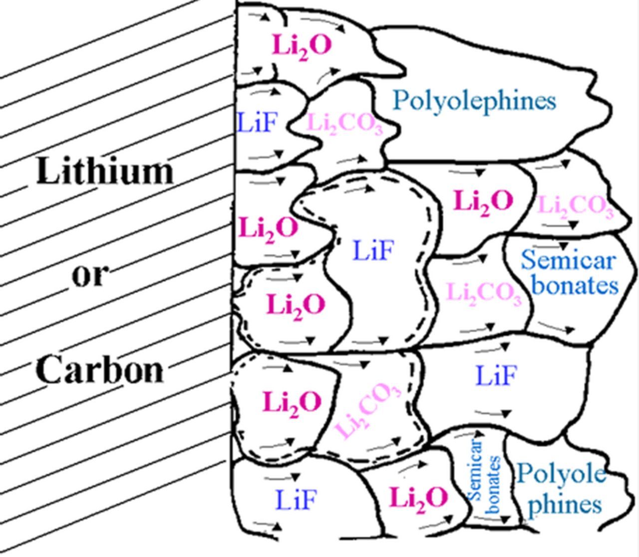
Figure 2. Schematic presentation of polyhetero microphase SEI.10
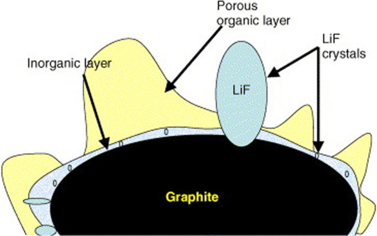
Figure 3. A schematic picture of the SEI on graphite particle.25
In our opinion, published in 1979, the SEI grows, by a corrosion process of the anode due to two pathways - conduction and diffusion of electrons through it, these are the RDS for the corrosion process.4 These electrons reach the SEI/electrolyte interface and reduces both solvent and salt anions. In a freshly formed SEI and in a contaminated SEI (for example by Mn, Co, Ni resulting from cathode dissolution), these processes are faster, mainly because of a higher content of crystal defects.
In both cases, on the assumption that all the corrosion products (or a constant portion of them) precipitate on the surface of the anode, the increase in thickness of the SEI follows a parabolic law with respect to the time of storage under OCV conditions (Equations 2 and 3). In 2001, Danh et al.22 concluded that the growth rate of the SEI slows approximately as a function of t−1/2, where t is the elapsed time since the beginning of cycling. Dahn's conclusion supports Peled's findings of 1979. As the SEI is a compact polycrystalline material solvent molecule or salt anions cannot transport through it. So, the SEI growth take place at the SEI/electrolyte interface and not at the anode/SEI interface. As said before, a strong support for this conclusion is the fact that polyolefins and semi carbonates, which are solvent reduction products are found (see Figure 1 and References 20–27) only at the outer part of the SEI near the SEI/electrolyte interface.
![Equation ([2])](https://content.cld.iop.org/journals/1945-7111/164/7/A1703/revision1/d0002.gif)
![Equation ([3])](https://content.cld.iop.org/journals/1945-7111/164/7/A1703/revision1/d0003.gif)
When the initial thickness of the SEI (Lo) is zero both equations yield a pure parabolic growth (Equations 2 and 3). There is an important question regarding the growth of the SEI during cycling of alkali metal and alkali ion batteries—does the SEI grow at all? If so, does this growth result in capacity fading? We should divide this issue into two processes, growth of the compact SEI and growth of the secondary SEI that results from the precipitation of electrolyte reduction products on top of the compact SEI forming a more porous, or structurally open layer, that suppresses the mass transport of ions in the electrolyte, filling its pores (see Figure 3 and SEI formation, kinetics and growth section). In lithium sulfur battery28 the thickness and the resistance of the SEI do not change during 200 cycles (see SEI on lithium anodes in lithium/sulfur batteries section). On the other hand, when cycling silicon nanowire anode149 the thickness of both the compact SEI and the secondary SEI increase (see SEI on silicon anodessection)
The deposition/dissolution process of an electrode (M) covered by an SEI, involves three consecutive steps, which are described schematically (for the dissolution process) as follows:
Electron transfer at the metal/SEI interface
![Equation ([4])](https://content.cld.iop.org/journals/1945-7111/164/7/A1703/revision1/d0004.gif)
Migration of cations (Mn+) from the metal/SEI (M/SEI) interface to the SEI-solution (SEI/Sol) interphase when tM+ = 1 (or migration of anions when tX− = 1). This migration takes place through lattice defects such as vacancies or interstitial defects.
![Equation ([5])](https://content.cld.iop.org/journals/1945-7111/164/7/A1703/revision1/d0005.gif)
Ion transfer at the solid-electrolyte interphase/solution (SEI/sol) interface for t M+ = 1
![Equation ([6])](https://content.cld.iop.org/journals/1945-7111/164/7/A1703/revision1/d0006.gif)
In principle, any one of these could be the rate-determining step (RDS). However, it was found, by the use of a variety of experimental techniques that, whenever there is no damage to the SEI during cycling, for example lithiation and de-lithiation of carbon anodes and for alkali metal anodes under OCV conditions or at low current density, ionic migration through the SEI is the rate-determining step. In such a case, the Tafel slope (b) is a linear function of the thickness of the SEI (Equation 6), thus no single Tafel slope is measured for SEI electrodes.4
![Equation ([7])](https://content.cld.iop.org/journals/1945-7111/164/7/A1703/revision1/d0007.gif)
Where Z is the valence of the cation (1 for lithium), α is the half–jump distance of the ion in the SEI and L is the thickness of the SEI. When alkali metal is deposited or dissolved at a very high current density, the SEI is very thin and contains a high concentration of lattice defects so reaction 2 may not be the RDS anymore. It is expected that the coulombic (faradaic) efficiency (ɛF) in the deposition/dissolution processes will decrease with increasing charge- and discharge-current densities.10
SEI structure
The transport of ions through the SEI, which consists mainly of polycrystalline material,5 takes place by mobile-point (Schottky or Frenkel) defects10 or at the grain boundaries positioned vertical to the surface of the anode. In the first models describing the SEI,4,29 its structure was represented as comprising two or more separate layers of different composition and properties. The first layer is thin and compact, while the second one (if it exists) on top of the SEI is a more porous, or structurally open layer (Figure 2), that suppresses the mass transport of ions in the electrolyte, filling its pores.
Later, Thevenin and Müller30 suggested several modifications to the SEI model: 1) the polymer-electrolyte-interphase (PEI) model in which the lithium in propylene carbonate (PC) electrolyte is covered with a PEI composed of a mixture of Li2CO3, P(PO)x and LiClO4; P(PO)x is polypropylene oxide, formed by reduction-induced polymerization of PC; 2) the solid-polymer-layer (SPL) model - where the surface layer is assumed to consist of solid compounds dispersed in the polymer electrolyte; 3) the compact stratified layer (CSL). In this model, the surface layer is assumed to be made of two sublayers. The first layer on the electrode surface is the SEI, while the second layer is either SEI or PEI. Aurbach et al.31 carried out an intensive electrochemical and spectroscopic study of carbon electrodes in lithium-battery systems. Based on the X-ray photoelectron spectroscopy measurements, they suggested multi-layered SEI structures.
We assumed that the reduction of salt anions and solvents proceed simultaneously and that both organic and inorganic materials precipitate on the electrode as a mosaic of micro phases.7,10,32 These phases may, under certain conditions, form separate layers, but we believe that it is more appropriate to treat them as polyhetero micro phases (Fig. 210). The equivalent circuit for a mosaic-type SEI electrode is extremely complex. The basis for Figure 2 can be found in Ref. 27. In this paper, all the SEI materials that are shown in the figure were determined by TOF-SIMS. The positions of the materials in the microphase mosaic were determined by TOF-SIMS and XPS depth profile (sputtering process) and their sizes were determined by TOF-SIMS.27,33 Thus, there is no doubt that the microphase distribution in the presented model10 reflects the nature of the SEI. The conduction mechanism of Li+ in the SEI is through vacancies and interstitial lattice defects. At the grain boundaries, the lithium-ion concentration is higher and so the conduction at the grain boundaries (vertical to the anode) is higher than in the bulk.
However, to a first approximation, a single-layer SEI is characterized by at least four resistance-capacitance (RC) elements in series and a Warburg impedance.10 These RC elements represent two interfaces - electrode/SE and SE/solution - SEI ionic resistance and capacitance, and grain-boundary resistance and capacitance. Each additional sublayer adds another three RC elements. The total SEI resistance (RSEI) in battery electrolytes is typically in the range of 10–1000 ohm.cm2. The expected value for Rgb at 30°C for a 10 nm SEI is between 10–100 ohm.cm2,7 i.e. it cannot be neglected and Rgb and Cgb must be included in the equivalent circuit of the SEI, for all anodes. It was suggested31 that in polymer electrolytes, lithium-passivation phenomena are similar to those commonly occurring in liquid electrolytes.
In recent studies, the SEI structure shows a bilayer structure in general, but in reality is more complex. For example, according to the results of Takenaka's hybrid Monte Carlo (MC)/molecular dynamics (MD) reaction simulation, inorganic salts such as Li2CO3 are abundant near the anode surface and distributed within the whole SEI film.34
In Figure 3 of their paper, Edström et al.25 describe and demons-trate the SEI as a heterogenic structure composed of LiF and Li2CO3 close to the electrode surface (inner film) and a porous organic or polymeric layer extending further out from the surface (outer film).
Balbuena et al.35 studied the polymerization mechanisms of electrolytes, which yield SEI growth. The authors concluded that electron transfer from the anode via tunneling would not be possible after the thickness of the SEI layer grows beyond ∼10 Å. However, a large number of radicals are produced in the initial stages of SEI nucleation. Some are adsorbed on the anode surface; others remain in the liquid phase and are able to propagate the reaction before the film is formed. Once some of the blocks begin to nucleate on the anode, these radicals, which have extremely high reactivity, can readily transfer charge to their surrounding environment. However, if the film is too dense, only small radicals such as lithium atoms would be able to penetrate the film. Thus, electrons will travel through blocks transported by lithium atoms as reaction-inducing agents and form radicals at the local level. Radical propagation would proceed especially through the organic layers, and once the radical reaches a molecule that can be attacked and decomposed, new radicals are generated, and the reaction continues. The authors found that polymerization reactions initiated by open vinylene carbonate (VC) or open-EC radical anions reacting with VC molecules are thermodynamically more favorable than those reacting with EC molecules.
Chemical Composition and Properties of the SEI on Inert Substrate and Lithium
Inert conductive substrate
Since it is easier to study SEI formation on inert substrates than on lithium metal, much information on this process has been obtained over the past forty years. Thorough studies of the chemical composition of surface films of lithium deposited on an inert substrate in a variety of electrolytes have been summarized in Refs. 1, 4, 10, 20–27. Because of limited space, we focus here on lithium-battery electrolytes. The structure and composition of the surface film on lithium in carbonate-based electrolytes have been extensively investigated.19,30,36–51 The electrochemical reduction of five organic carbonates - EC, PC, DEC, DMC and VC - were studied with the use of cyclic voltammetry at a gold electrode in THF/LiClO4 supporting electrolyte.52 The reduction potentials of all the carbonates were above 1 V (vs. Li/Li+), with EVC being the most positive. In Ref. 52 it was shown that the preferential reduction of vinylene carbonate appears to favor SEI formation.
Aurbach and Zaban18 have found that the lithium surface deposited on a nickel electrode in carbonate-based electrolytes is covered with Li2CO3, LiOH, Li2O, LiOR, LiOCO2R (R = hydrocarbon) and lithium halide. Their recent studies revealed that traces of oxygen, water and PC-reduction products form passivating surface films on gold, platinum, silver, nickel and copper electrodes, when these are polarized to low potentials in lithium-salt solutions.53 In the study it was also found that the major constituent in the surface films is the PC-reduction product, CH3CH(OCO2Li)CH2OCO2M. When a small amount of HF is added to PC containing 1.0 M LiClO4, the lithium deposited on a nickel substrate is covered with a thin surface film of LiF/Li2O. However, without the addition of HF, the surface of electrodeposited lithium is covered with a thick film (mainly LiOH and Li2O). The RSEI values for LiPF6/PC and LiN(SO2CF3)2/PC were about 800 and 23 ohm.cm2, respectively. Such high RSEI may be caused by the presence of highly reactive HF in the LiPF6 electrolyte. The addition of CO2 to the solutions considerably reduced the interfacial resistance. Using a Voigt-type analog model, Aurbach calculated the thickness and resistivity of the SEI. The average thickness of the interphase next to the lithium is about 30–50 Å and the resistivity is on the order of 0.1-0.2 × 10⁸ ohm.cm.
The higher resistivity of the SEI in LiPF6 and LiAsF6 solutions as compared to solutions of other salts, was explained by the replacement of the ROCO2Li surface species by LiF. The author concluded that it is not an increase in the SEI thickness, but rather resistivity changes that contribute to species-controlled resistance and lead to the high interfacial impedance of the lithium anode in LiPF6 and LiAsF6 electrolytes. In addition, Li2CO3 is stated to be one of the best passivating agents for the enhancement of lithium-cycling efficiency.53
Lithium
Several techniques have been applied in the electrochemical analysis of lithium electrodes in a large variety of electrolyte solutions. An important finding as a result of these studies is that the passivation of fresh lithium in polar aprotic electrolytes may be completed in less than one second. As with lithium deposited on an inert substrate, the XPS spectra of lithium electrodes, covered by native film and treated in fluorine-containing salts such as LiAsF6, LiBF4, LiPF6, Li-imide and Li-triflate dissolved in THF, always show fluorine, oxygen and carbon peaks.37 Methyl formate is the most reactive solvent toward lithium, as compared to other polar aprotic solvents including ethers, BL (butyrolactone), (propylene carbonate (PC) and EC. Even in the presence of trace amounts of water and methanol contaminants, it is reduced to lithium formate as a major precipitate.41 The presence of CO2 in MF causes the formation of a passivating film containing both lithium formate and lithium carbonate. In PC solutions, the lithium/solid-electrolyte interphase was shown to be mainly a matrix of Li alkylcarbonates.18 In PC-based electrolytes, LiPF6, LiBF4, LiSO3CF3, LiN(SO2CF3)2 were found to be more reactive toward lithium than were LiClO4 and LiAsF6.37 In the case of EC/PC or EC/ether mixtures, the reduction of EC by lithium seems to be the dominant process, followed by the formation of lithium alkyl carbonates.43 Addition of cyclic compounds with heteroatoms and conjugated double bonds, such as 2-methyl-thiophene (2MeTp), 2-methylfurane (2MeF), and simple aromatic compounds like benzene is very effective in electrolyte solutions for rechargeable lithium batteries.48–49 In the presence of surfactants like polyethylene glycol dimethylether and a mixture of dimethyl siloxane and propylene oxide in EC/DMC solutions, smooth surface morphology and almost constant thickness of the lithium passivating film were observed.54
Solid polymer and gel electrolytes
It seems likely that in polymer electrolytes, especially in the gel types, lithium-passivation phenomena are similar to those commonly occurring in liquid electrolytes.10 Results obtained with PEGDME electrolytes containing different salts showed that the formation of LiF as a result of the reduction of anions like AsF6− or CF3SO3−, plays a key role in the lithium-passivation mechanism.55 The authors showed that SEI formation was apparently complete in just 2–3 minutes. The increase in the SEI resistance (RSEI) over hours and days is apparently due to the relaxation of the initially formed passivating films or to the continuation of the reaction at a much slower rate. In Ref. 56 the formation and properties of the lithium SEI was studied in different types of hybrid and gel electrolytes based on polymers and organic solvents combined with organic or inorganic gelation agents.
LiI-tetraglyme-based hybrid electrolytes with PVDF-silica membrane form SEIs that are highly stable for more than 3000 hours.10,57 The three-fold increase in the RSEI of Li2imide HPEs after 300 hours of storage and about an order of magnitude increase after 2000 hours, provides evidence of the thickening with time of the passivating layer on lithium. The low and almost constant resistance of the SEI in lithium iodide-containing electrolytes, may be associated with the thermodynamic stability of the iodide anion toward metallic lithium. The incorporation of nano-size ceramic fillers in a polymer membrane improves interfacial resistance in hybrid as well as in composite solid polymer electrolytes;32,57 this is due to the ability of the ceramic fillers to adsorb impurities and traces of water. In addition, inorganic fillers may prevent free diffusion of the liquid electrolyte components to the lithium surface and, as a result, inhibit the growth of the SEI It is worth noting that the conductivity of the lithium passivating film in silica-containing HPEs is twice that of the alumina-based HPEs.
The morphology of lithium deposits from 1–3M LiClO4-EC/PC-ethylene oxide (EO)/propylene oxide (PO) copolymer electrolytes was investigated.58,59 It was found, that as the weight ratio of host polymer to liquid electrolyte increased, fewer lithium dendrites were formed, with no dendrites found in electrolytes containing more than 30% (w/w) host polymer. The authors emphasized that good contact between the polymer and lithium is also of great importance for the suppression of dendrites. Direct in-situ observation of lithium dendritic growth in Li-imide P(EO)20 polymer electrolyte60 shows that dendrites grow at a rate close to that of anionic drift.
The interfacial phenomena in solid LiX/PE systems were extensively studied by Passerini et al.61 For the dry PEO-based polymer electrolytes it was shown that the interfacial stability can be significantly enhanced by lowering the ceramic-particle size to the scale of nanometers.62–64
Carbonaceous Electrodes
Principles of SEI formation
Surface structure and chemical composition65–67 affect the physicochemical properties of carbon. The most important parameters determining the use of carbon as anode material are particle shape and size, pore-size distribution and pore opening, surface area and content of surface species and impurities. The carbon sheets (graphenes) are stacked in an ordered or disordered manner to form crystallites. Each crystallite has two different edge sites: the armchair and zig-zag sites. The reactivity of carbon atoms at the edge sites (and near lattice defects and foreign atoms) is much higher than that of carbon atoms in the basal planes.65–67 Consequently, the physical and chemical properties of carbon vary with the basal-plane to edge-plane area ratio. Actually, the edge atoms in completely closed pores are radicals and are said to have a "dangling" bond.68 These pores are responsible for the "extra" reversible capacity of disordered carbons69 and oxidized graphite.70–73
In lithium-ion batteries, the first intercalation capacity is larger than the first deintercalation capacity. This difference is the irreversible capacity loss (QIR). Dahn et al.74 were the first to correlate QIR with the capacity required for the formation of the SEI. They found that QIR is proportional to the specific surface area of the carbon electrode and, assuming the formation of a Li2CO3 film, calculated an SEI thickness of 45 ± 5Å on the carbon particles, consistent with the barrier thickness needed to prevent electron tunneling.1,4
The first lithium intercalation to the carbon,6,10,72,75 is very complex (Figure 1). The current understanding of this process is based on the principle that solvated lithium ions in the electrolyte lose their solvation shells while penetrating the SEI and are incorporated into the carbon structure in a solvent-free form. Such reactions are to be desired. In some cases, however, lithium intercalates together with its solvate shell, thus causing exfoliation of the electrode; these, of course, are undesirable processes. Exfoliation may result in complete destruction of the structure of graphite, large irreversible capacity and almost zero reversible capacity in cases where the reduction of the solvated molecules produces gas. In Refs. 13,37 it was shown that, in order to slow the co-intercalation of the solvated ion, and to enhance the formation of the SEI at the most positive potential (far from the Li/Li+ potential), the solvents appropriate for lithium-ion batteries employing a graphite anode must have high solvation energy, high E0 and high i0 for reduction.
At the electrode surface there is competition among the following processes: reduction reactions of salts, solvents and impurities, the rates of reactions which are influenced by i0 and η for each process and by the catalytic properties of the carbon surface. The products of reduction of salt anions are typically inorganic compounds like LiF, LiCl, Li2O, which precipitate on the electrode surface. Reduction of solvents is followed by the formation of both insoluble SEI components like Li2CO3 and partially soluble semi-carbonates and polymers. The voltage at which the SEI is formed depends on the type of carbon, the catalytic properties of its surface (ash content, type of crystallographic plane, basal-to-edge plane ratio), temperature, concentration and types of solvents, SEI precursors, salts and impurities, and on the current density. For lithium-ion-battery electrolytes, VSEI is typically in the range 1.7–0.5 V13 vs. Li reference electrode, but the SEI continues to form down to 0 V. In some cases, ɛF is less than 100% during the first few cycles.76 This means that the completion of the SEI formation may take several charge/discharge cycles.
In addition to the building of the SEI, QIR may be caused by capacity associated with the formation of soluble reduction products (QSP), Figure 1,6,10,72 with the trapping of lithium inside the structure of the carbon (QT),69 and with unused capacity under specified experimental conditions (Qu). QSEI, as well as VSEI, depends on the morphology of the carbon and should increase with the ratio of cross-sectional-plane area to basal-plane area. This conclusion stems from the data reported by Besenhard et al.77 on the penetration of the passivating layer into the graphite sheets through the cross-sectional planes. This agrees with,78 where the thickness of the SEI at the cross-sectional planes of an HOPG crystal was found to be greater than that of the basal plane. Factors that are reported to lower QIR are: increasing the EC content in organic carbonates or dioxolane solutions,77,79 addition of CO243,77,79 or crown ethers,80,74,81 adding SEI precursors like VC fluoro ethylene carbonate (FEC), 2FEC35 and increasing the current density.71
Every parameter and property of the SEI significantly affects battery performance. Irreversible capacity loss (ICL) in the first cycle occurs as a result of salt and solvent reduction and is hence a characteristic of the SEI.
Contamination-free SEI is mandatory for the cycle life of the battery. It becomes even more important during cycling at high rates and at greater depth of discharge. SEI properties are temperature sensitive, especially at low and high temperatures, and thus affect the performance of the battery at these temperatures. Detrimental processes occurring during high-temperature storage lead to a severe increase in the thickness of the SEI and to the reduction of battery power and capacity. However, the most important issue regarding the SEI is its effect on the safety of the battery. This includes its ability to minimize the risk of dendrite formation under overcharge conditions and to minimize the risk of high-temperature dissolution of some SEI components that might lead to thermal runaway of the battery. The chemical composition of carbon/graphite surfaces may also affect the exchange-current density of the reduction of SEI precursors and the potential for SEI formation, as well as the wettability of the electrolyte and the chemical bond between carbon and the SEI. The presence of oxygen species on graphite surfaces increases the reduction potential vs Li/Li+ and helps early SEI formation before lithium intercalation.9
Commercial electrolytes for lithium ion batteries consist of EC, DEC, DMC and LiPF6; some contain low concentrations of additives such as FEC, DFEC and VC. In these electrolytes, the SEI forms quickly by reduction of EC, FEC, DFEC, VC and LiPF6 and its compounds are the least soluble. High EC content increases the viscosity and the solubility of some SEI components and thus is not recommended. The reduction of FEC, DFEC and PF6− produces LiF which is a good Li+ conductor with a value of t+ equal to unity. Reduction of EC, FEC, DFEC and VC leads to the formation of polymers, mainly polyolefins.
Graphite and HOPG
The SEI composition of the basal and the cross-sectional planes of HOPG in LiPF6 EC:DEC electrolyte was studied.82,83 Several species were found via XPS on the basal plane, including: polyolefins, carbonates, semi-carbonates Li-O-C group, C-O-H and/or C-O-C that may be associated with oxygen-containing polymeric species formed on solvent decomposition. No carbonates were found in the XPS spectra of the SEI built on the cross section of HOPG.
In addition, it should be mentioned that in the bulk SEI on the cross section of HOPG the Li/F ratio is close to one, thus the oxygen may be bound to organic or phosphorus compounds, the distinctive feature of the basal SEI is the presence of 10 to 30 atomic % Li2CO3 on the surface and in the bulk.82,83 It was shown unambiguously that the basal SEI is thinner than the cross-sectional one.
Time-of-flight secondary-ion mass spectrometry (TOF SIMS) measurements were carried out for the first time at one-micron lateral resolution for a study of the SEI formed on the different planes of HOPG in LiPF6 EC:DEC electrolyte.33,83 According to the TOF SIMS spectra, fragments containing lithium, fluorine, oxygen, carbon and hydrogen were found in the SEI on both the cross-sectional and basal planes. It was found that lithium and fluorine dominate the cross-sectional SEI spectrum and organic species dominate the basal spectrum, in good agreement with the XPS data. The solution-side surface of the basal SEI is very rich in C2H3O. The normalized intensity of C2H3O is four times that of lithium, indicating that most of it cannot be bound to LiOC groups in alkyl carbonates or alkoxides. The apparent SEI thickness was calculated by taking the depth at half-signal intensity. The intensity of secondary-ion counts of all species falls to one half of its maximum value after about 0.5 to 2.5 nm at the basal plane and about 1.7 to more than 30 nm (for fluorine) at the cross section. The secondary-ion signal of the same species falls 1.7 to 5.5 times (or more) faster at the basal plane than at the cross section. SEI thickness measured by XPS for SEI formed under similar conditions is 7 nm for basal SEI and 35 nm for cross-sectional SEI. A thick SEI at the cross section was generally explained by solvent co-intercalation and exfoliation of the graphite.27,77,84,85 This must be followed by the formation of carbonates as a result of solvent reduction. However, carbonates were not found, neither on the solution-side surface nor in the bulk of the cross-sectional SEI. As opposed to the cross-sectional SEI, the bulk SEI contains up to 30 atomic % of lithium carbonate. Therefore, its absence in the cross-sectional SEI cannot be explained by the reduction of Li2CO3 to alkoxides alone. XPS data showed that the major cross-sectional SEI compound is LiF, (up to about 90 atomic percent - excluding H atoms - in the bulk). The normalized counts of PO3− species, recorded by TOF SIMS at the cross section, are about three times higher than at the basal plane. These two findings clearly show that the exchange-current density for LiPF6 (and for HF) reduction is much higher at the cross section than it is at the basal plane. We believe that this is the reaction that determines the cross-sectional SEI composition. The increased thickness of the cross-sectional SEI as compared to the basal SEI may be explained by the co-intercalation of ion aggregates like Li2PF6+ at the beginning of SEI formation. This is followed by Li2PF6+ reduction to the PO3− species detected by the TOF SIMS. Possible co-intercalation of protons as products of HF dissociation cannot be excluded either. Partial exfoliation of graphite by Li2PF6+ and hydrogen penetration may also cause an increase in the SEI thickness.
Polyolefins do not conduct ions and their content in the SEI is an important issue. On the one hand, their softness can add flexibility to the SEI and fill voids. On the other hand, excessive polymer content can block lithium migration in the SEI. Polymers may cause uneven current distribution and uneven lithium intercalation.
According to XPS and TOF-SIMS, Peled et al. concluded that SEI is thicker at lower potentials (lithiated state of carbon) and thinner at higher potentials (delithiated state).86 However, these changes are more pronounced at elevated temperatures. There are several prime reactions that occur on elevating battery temperatures: transformation of SEI, the reaction of active material with the SEI, SEI with the electrolyte or active material with the electrolyte. The components like lithium alkyl carbonates and semi-carbonates convert to stable components like Li2CO3. However, the temperature at which this occurs is highly dependent on the salt and solvent of the electrolyte, the type of carbon material, and its specific surface area. The reaction of active material with the SEI, or SEI with the electrolyte, or active material with the electrolyte begins at 120–140°C. At this temperature, the transformed SEI allows lithium from carbon to encounter the electrolyte and allows electrons to pass through the SEI. Beyond this temperature, even more exothermic reactions, like that of lithiated carbon with binders, occur. All these exothermic processes are detrimental to the performance of a Li-ion battery and are dangerous from the safety point of view.86 In addition, at elevated temperatures, polymers and other organic materials (such as alkyl carbonates) may dissolve, leading to discontinuity in the SEI and this can trigger a thermal runaway. Thus, many efforts have been made to detect polymers in the SEI. Continuous production of active alkyl radicals in the electrolyte during the first lithium intercalation was detected by Endo87 with the use of the electron-spin-resonance method (ESR). Evidence of hydrocarbons in the SEI was found by SIMS analysis in Ref. 88. The appearance of large numbers of counts of C and CH species, especially at the basal plane, supports previous claims for the existence of polymers in the SEI. The most convincing evidence is the CH2 sequence found on the basal plane. A sequence of masses: 311, 325, 339, 353, 367 – with a common difference of 14, can clearly be assigned to polyolefins, (CH2)n.
In basal SEI, lithium and fluorine are concentrated in large regions (100 microns), with some smaller micron-sized particles. There is little or no correlation with graphite topography. The distribution of CH2 (and other CxHy-based fragments), O, C2H3O2,69 and C2H3O,89 indicates full coverage and is fairly uniform. C2H3O is the major component of the basal SEI. Since the TOF SIMS images for all negative and positive ions were recorded simultaneously from almost the same region, it is fair to say that there is an overlap of lithium and fluoride distributions with those of the organic species; this indicates an intimate mixture of these species at the submicron level. This agrees with the polyhetero-microphase-structure model of the SEI.
Graphite with low specific surface area tends to exfoliate more. As the surface area is decreased, by heat-treatment (Argon or vacuum atmosphere, 950–250°C), the number of surface defects increases and the exfoliation tendency of the graphite increases further. The degree of graphite crystallinity is also an important factor in SEI formation and highly ordered graphite is preferred for high-energy LIB anodes. When the particle size is small, irreversible capacity loss increases because of the larger surface area for lithium inventory loss during SEI formation.9
Carbons
It has been reasonably well established that the intercalation capacity of lithium and the operating voltage of the lithium-ion battery depend on the properties of the SEI. The formation of the SEI, in turn, is strongly affected by the crystal structure of graphite. Successful development of negative electrodes for lithium-ion batteries requires an understanding of how irreversible-loss processes correlate with carbon-surface activity and structure. Many materials given the name graphite actually have a considerable amount of stacking disorder. For carbons in general, the situation is more complex. Most cokes, petroleum cokes, carbon blacks, carbon fibers, pyrolyzed polymers and mesocarbon microspheres have disordered structures. In such structures, the crystallites are small and there is a high probability of random stacking (shifts or rotations) of adjacent carbon layers. This type of disorder is called turbostratic disorder. Hundreds of carbons are commercially available; however, selecting the best carbon for use in lithium-ion cells is the subject of much current research.
Electrochemical and spectroscopic methods88 have been used to investigate irreversible-loss mechanisms of lithium intercalation in disordered polymethacrylonitrile carbons. Voltammetric measurements show that the solvent readily decomposes at potentials 1.2 V positive of the reversible lithium potential. Evidence for hydrocarbon, carbonate and alkyl carbonate formation in the surface film is found with the help of combined XPS and SIMS analysis. It has been suggested that the substrate has a more pronounced influence on SEI formation on carbonaceous materials than does the electrolyte. The disturbed graphite structure of hard carbon is characterized by high catalytic activity, which favors decomposition of the electrolyte which is followed by increased content of carbonates in the SEI formed in the LiAsF6 electrolyte, and of LiF and phosphorus-containing compounds in the SEI in the LiPF6 electrolyte.
A comparison of the composition of the SEI formed on the disordered carbons and on HOPG,27,33,78,83,90–92 leads to the conclusion that SEI content on hard carbon is similar to that formed on the cross-section of HOPG, while the composition of the SEI on soft carbon is close to that on the basal plane (Figure 310).
Overview of SEI composition and properties in different carbon/nonaqueous-electrolyte systems
Ideally, the SEI layer should be uniformly distributed over the carbon surfaces. The chemical composition of the SEI should contain stable and insoluble compact inorganic compounds such as Li2CO3 rather than metastable organic compounds such as ROLi and ROCO2Li (where R is a low-molecular-weight alkyl group). This is important for confining the loss of lithium to the first few cycles and minimizing irreversible capacity loss. The insolubility of SEI components in the electrolyte is very important for high capacity retention, since losing the components may induce new SEI formation where they dissolved.9
It has been emphasized that irreversible reactions, including gas evolution and disintegration, have been mainly observed on that part of the surface occupied by the edge planes of acetylene black, activated carbon and vapor-grown carbon fiber in LiClO4/PC solution.93 Aurbach et al. extensively studied the electrochemical and spectroscopic characteristics of carbon electrodes in lithium-battery systems.94,95 LiClO4, LiAsF6 and LiBF4-based electrolytes with MF, PC, EC, THF, DME, 1,3-dioxolane solvents were tested. The carbons investigated included carbon black, graphite and carbon fibers. It was found that the SEI films are similar in their chemical structure to those formed on lithium in the same solutions. Thus, PC is reduced on carbon to ROCO2Li, ethers are reduced to alkoxides, MF to lithium formate. CO2 reacts with LixC6 to form Li2CO3 (and probably CO). Because of the high surface area of graphite particles as compared to the lithium-metal electrode, the role of contaminants, such as HF in LiPF6 and LiBF4-based electrolytes, is much less pronounced.96 The beneficial effect of inorganic additives, such as CO2, N2O, Sx2−, etc., on the formation of the SEI on carbons, was emphasized.94,95,97
Interesting results were obtained by Ein-Eli et al.,98 who showed that the use of SO2 as an additive to LiAsF6/MF or LiAsF6/PC, DEC, DMC solutions offers the advantage of forming fully developed passivating films on graphite at a potential much higher (2.7 V vs Li/Li+) than that of electrolyte reduction (<2 V vs Li/Li+) or of lithium intercalation (0.3 to 0 V vs Li/Li+). The major surface species are: inorganic lithium salts (LixAsFy, Li2CO3, Li2SO2O4, Li2SO3, Li2S2O5 and Li2S) and organic lithium alkyl carbonates (ROCO2Li). Using cyclic voltammetry, Inaba et al.99 found that for graphite electrodes an EC+DEC solvent mixture is preferred over EC+DME with respect to the formation of a stable passivating film. When graphite electrodes are charged in PC-based solutions, the solvent decomposes at about 1 V, and this makes SEI formation difficult.
Using XRD and electrochemical quartz-crystal-microbalance techniques, Morita et al.100 showed that the cathodic intercalation of lithium is accompanied by electrochemical decomposition of the electrolyte. The mass change per coulomb over the potential range of 0.0 to 0.2 V vs Li/Li+ was higher in EC-DMC than in EC-PC, indicating different surface reactions. The values of mass accumulation per mole of electrons transferred,101 calculated for the surface species, were smaller than those of the expected surface compounds (mainly (CH2OCO2Li)2). This was attributed to the poor stability of the SEI and its partial dissolution. An unstable passivating layer on petroleum coke in Li-triflate/EC-PC-DMC, followed by interaction between the electrolyte and the intercalated lithium was observed by Jean et al.102 It was concluded103,104 that on long cycling of the lithium-ion battery, the passivating layer on the carbon anode becomes thicker and more resistive, and is responsible, in part, for capacity loss.
The mechanism of formation of the passivating film at the interface between lithiated carbon and a liquid or polymer electrolyte was studied by AC-impedance.105,106 Yazami et al.105,107 explained the complicated arc shape by surface-film formation followed by electrode gassing during the decomposition of the electrolyte. A depressed high-frequency arc may be due to the overlapping of two, or even more arcs and may be associated with grain-boundary resistance in the SEI.7,10 In another investigation108 it was found that the interfacial resistance of graphite electrodes in LiPF6 and LiBF4/EC-DMC solutions is about one order of magnitude higher than that of LiAsF6-based electrolytes and increases considerably upon storage.
Yazami et al.105,109 studied the mechanism of electrolyte reduction on the carbon electrode in polymer electrolytes. Carbonaceous materials such as cokes from coal pitch and spherical mesophase and synthetic and natural graphites, were used. The change of Rfilm with composition on LixC6 electrodes was studied for three ranges of x in a Li/POE-LiX/carbon cell.105 The first step in the lithium intercalation (0 < x < 0.5) is characterized by a sharp increase in Rfilm. Such intercalated lithium is irreversible in the 1.5–0.5 V range. In the second step, (x∼1), lithium intercalates mainly into the coke and the film does not grow significantly, thus a slow increase of Rfilm is observed. In the third step, excess lithium is formed on the surface of the coke inside the film, inducing a further increase in the film thickness and its resistance.
The relation between surface properties, pore structure and first-cycle charge loss of different natural and TIMREX graphites in LiPF6 EC: DMC electrolytes was studied by Joho et al.110 The graphites studied were as follows: KS6-KS44, SFG6-SF44, T15-T44, SLM44, E-SLX20-50 and E-NP15. They found that the geometrical surface area of the natural graphite particle, excluding the mesopores, contributes more to the BET surface area and to the irreversible capacity of the first electrochemical reduction than does that of the synthetic graphites. The synthetic graphite samples exhibit more highly developed mesoporosity, while the natural graphite has a rougher surface, so that similar values are recorded for their BET surface areas and for the irreversible capacities in the first reduction of the corresponding graphite negative electrodes. In-situ neutron radiography carried out before and after cycling of commercial prismatic lithium-ion cells (ICP-340848)111 revealed displacements of excess electrolyte, most probably as a consequence of an expansion/contraction of the electrodes as well as evolution of gases during SEI formation. The relationship between the elevated-temperature performance of Li/graphite half-cells and the composition and morphology of the SEI formed on the graphite (TIMREX KS6) surface has been investigated for two electrolyte systems: 1M LiPF6 in ethylene carbonate and dimethyl carbonate (EC/DMC) (2:1) and 1M LiBF4 in EC/DMC (2:1).112 Pre-cycled cells were stored at different temperatures up to 80°C, and the graphite electrodes were analyzed by XPS and electrochemically under continued cycling. The morphology and the SEI were found to change on storage at elevated temperatures. The surface of the electrodes also shows an increasing amount of polymeric compounds. Studies of the low-temperature behavior of the MCMB Li-ion cells with gel-type PVdF-based electrolyte prepared with Bellcore technology were conducted.113 It was found that even at modest (C/5) to low (C/10) rates of charge and discharge, batteries show permanent capacity loss at temperatures ≤ 20°C. This loss is attributed to continual growth of the SEI resulting from electrolyte reduction.
Lanz and Novak111 studied gas evolution at thick graphite electrodes in γ-butyrolactone EC: DMC electrolyte by differential electrochemical mass spectrometry (DEMS). TIMREX SPG 6, SPG 15 and SPG 44 carbons were tested. They found that SEI formation on these thick electrodes was not yet complete after the first charge/discharge cycle. The amount of ethylene and hydrogen gas evolved decreases with increasing percentages of GBL in an EC/DMC electrolyte, indicating that the SEI layer is built up from GBL rather than from EC-decomposition products.
In order to improve the cycling performance of lithium-ion batteries with nonflammable trimethyl phosphate (TMP)-based electrolytes, amorphous carbon (AC) was tested as the anode material.114 It was found that the reduction decomposition of TMP solvent, which occurred without limit on a natural graphite anode and concomitantly generated a large amount of methane (CH4) and ethylene (C2H4) gases, was considerably suppressed on an amorphous carbon anode. The charge/discharge data and cyclic voltammetry indicated the formation of a highly stable and passivating surface film on the carbon surface at a potential near 1 V. As a result, an AC/LiCoO2 cell with 1 mol/dm3 LiPF6 EC:PC:DEC:TMP (30:30:20:20) nonflammable electrolyte exhibited promising cycling performance.
In terms of safety, the ionic-liquid-based inorganic electrolyte - LiBF4 in 1-ethyl-3-methylimidazolium tetra fluoroborate (EMI-BF4) - is one alternative because of its higher boiling point than that of LiPF6 in EC/DEC and non-flammability. EMI-BF4 also has a higher oxidation potential, but its ionic conductivity is lower as a result of the high solvent viscosity.9
Balbuena et al.35 suggested that successful additives such as VC or FEC lead to compact SEI layers (usually containing stable polymer species) and to a relatively stable outer organic-SEI layer and thus to controlled growth. By contrast, electrolytes that do not contain these additives lead to an outer layer containing unstable species prone to radical attack and continued growth. The great advantage of VC and FEC as additives is their rapid polymerization. Polymers are much less prone to be reduced by a radical attack. If the outer organic layer contains less of the electrochemically unstable species (as in a VC or FEC based electrolyte), the SEI growth rate will significantly decrease compared with those based on VC- or FEC-free electrolytes. Generally, any species with a high reduction potential that, upon reduction, generates products that are electrochemically stable, will be a favorable additive for the SEI.
PC as an electrolyte solvent has excellent properties, with the exception of exfoliating the graphite during unstable SEI formation. Wagner et al.115 improved anode SEI formation by using methyl vinyl sulfone (MVS) and ethyl vinyl sulfone (EVS) additives in PC. These additives decomposed on graphite and built protective SEI layers before PC could intercalate and react because MVS and EVS have 1.3 eV and 1.2 eV lower LUMO energies, respectively, than does PC.
As the appreciation of having a stable, durable SEI has grown since the early 1990 s, much effort has been dedicated to: 1) improving its formation by using additives that result in better SEI-layer architectures, 2) modifying the anode surface for improving exchange-current density and charge/discharge reaction kinetics, 3) implementing charge/discharge cycles that enhance layer formation and 4) developing alternative electrolytes that result in less lithium-inventory loss during formation.9
Few studies have been reported on electrolyte wetting of electrodes, although it is an important factor in reducing SEI formation time and manufacturing resources that directly affect LIB-pack cost. In fact, wetting takes the most time of cell production and involves many of the latter manufacturing steps such as addition of insulators, seals and safety devices. Wetting electrodes (at low vacuum pressures during electrolyte filling and subsequently at elevated temperature after cell-sealing) with electrolyte and forming SEI layers, requires ∼0.5–2 weeks for the entire process. Wood et al.116 reported costs for a general wetting and formation process, which showed that SEI formation can contribute up to $32 to $33/kWh of usable energy for the battery-pack cost (out of a total cost of ∼$500/kWh). Wettability of the electrolyte into the electrode pores can be enhanced by lowering the surface tension of the electrolyte with an additive(s) or by increasing the composite surface energy of the electrode.9
Improved SEI and anode performance by surface modification
Surface pretreatment of graphitic electrode materials for lithium-ion cells has recently been shown to significantly reduce the irreversible consumption of material and charge. This improvement is due to the formation of an optimized SEI. It was found6,71–73,75 that mild air oxidation (burn-off) of two synthetic graphites and natural graphite (NG7) improves their performance in Li/LixC6 half-cells. The reversible capacity of the graphite increased (up to 405 mAh/g at 4–11% burn-off), its irreversible capacity was generally lower and the degradation rate of the LixC6 electrode (in three different electrolytes) was much lower. STM images of these modified graphites show nanochannels with openings of a few nm and up to tens of nm. It was suggested that these nanochannels are formed at the zig-zag and armchair faces between two adjacent crystallites and in the vicinity of defects and impurities. Performance improvement was attributed to the formation of SEI chemically bonded (CB-SEI) to the surface carboxylic and oxide groups at the zig-zag and armchair faces, better wetting by the electrolyte and to accommodation of extra lithium at the zig-zag, armchair and other edge sites and nanovoids. The mechanism by which partial oxidation increases the reversible lithium capacity is believed to be related to lithium bonding at edge atomic sites, as opposed to intercalation between graphene sheets. By 7Li NMR measurements it was found that the edge-site population is enhanced in the partially oxidized carbon.117 In particular, oxidation proceeds most rapidly at the zigzag and armchair sites, and results in the formation of COOH acid groups, which have been detected directly (along with CH, COH and C=O groups) by XPS.118 From the analysis of XPS spectra by curve-fitting, it was shown that the pristine NG7 surface contains mostly (53%) aromatic carbon, about 20% each of CH and COH groups, only 4.8% CO groups, and no COOH groups. The 34% burn-off sample consists mainly of CO groups (33%), C-OH groups (26.6%) and 8.9% COOH groups. Solid-state 7Li NMR measurements119 revealed two kinds of lithium sites in lithiated pristine graphite: lithium intercalated between graphene planes, with ∼40 ppm Knight shift (relative to aqueous LiCl), and lithium chemically associated with the SEI, characterized by a chemical shift of about 0 ppm. The burnt graphite also exhibited a signal at about 14 ppm, correlated with the excess lithium and attributed to lithium bonded to edge sites. In addition, the 7Li signal associated with the SEI was more intense in the burnt graphite, consistent with earlier indications that mild oxidation prior to lithiation results in a thicker and more salt-rich SEI. This graphite modification, following mild burn-off, was found to make the LixC6 electrode performance more reproducible and less sensitive to electrolyte impurities.
Decomposition of the SEI is generally seen as being one of the major factors influencing the thermal stability of the graphite electrode in lithium-ion cells.112,120–122 The effect of mild oxidation of natural graphite (NG7) and some other parameters on the reaction between a fully lithiated graphite anode (LixC6, x = 1.0 - 1.1) and 1 M lithium hexafluoroarsenate, 1:2 (v/v) ethylene carbonate and diethyl carbonate electrolyte were studied by differential-scanning calorimetry (DSC).123 Figure 510 shows the DSC traces for the washed and fully lithiated graphite/5μL electrolyte samples. It can be seen that only one exothermic peak exists at about 210°C. In the DSC run of the pristine graphite sample, the exothermic reaction produces a great amount of heat and releases much gas, causing an explosion of the DSC pan. In the case where the graphite was mildly oxidized (although it contains 10% more lithium), the explosion was prevented. In addition, the exothermic peak of the mildly oxidized graphite was depressed and shifted from 210 to 214°C. In order to decrease the surface area of separation, the small graphite particles were removed. This modification of the burnt graphite resulted in a dramatic lowering of the peak height (from 225 W/g for the burnt sample to 25 W/g for the modified sample). In addition, the energy of the exotherm and the reaction rate decreased from 3610 to 1460 J/g and from 10 to 2 W/g°C, respectively. The exothermic peak is preceded by a small endothermic peak (A in insert of Figure 4). It is suggested that this endothermic peak can be attributed to the decomposition of some SEI materials such as polymers, ROCO2Li, (CH2OCO2Li)2 and ROLi. Decomposition of such products at 200°C was analyzed by temperature-programmed-desorption mass spectrography (TPD-MS).113 In addition, it is expected that polymers and semi-carbonates will dissolve in the electrolyte at high temperatures. The dissolution and decomposition processes can lead to the destruction of at least part of the SEI. This would be followed by a vigorous reaction of the lithiated graphite electrode, with the electrolyte. The formation of the chemically bonded SEI at the cross section may help to, at least partially, avoid or slow the exfoliation of the graphite crystallites during the thermal reaction with the electrolyte.
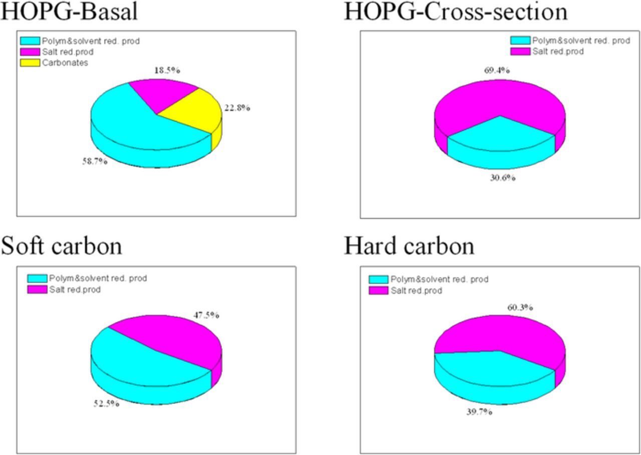
Figure 4. Estimated composition of the SEI on HOPG and soft and hard carbon in LiPF6 electrolyte.10
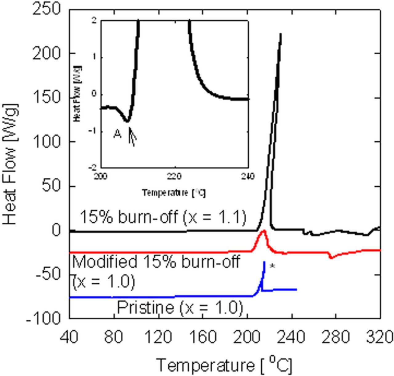
Figure 5. DSC thermograms of fully lithiated graphite-electrolyte samples (the modified and the pristine samples were shifted by −25 W/g and −75 W/g, respectively). The electrolyte/graphite ratio is 5 μL/2 mg. The heat-flow values are in units of Watts per gram of graphite. *sample exploded.10
Tibbetts et al.124 showed that oxidative pretreatment of vapor-grown carbon fibers (VGCF) can reduce the capacity of SEI forming in LiClO4/PC electrolyte by an order of magnitude. Their experiments confirm the idea that air etching removes the more active carbon atoms - those capable of decomposing the electrolyte - and completely alters the fiber morphology. It was found125 that chemical oxidation of graphite powder by strong oxidizing agents, such as ammonium peroxysulfate and hot concentrated nitric acid, gave similar results, i.e. it suppresses QIR and enhances QR to 410–430 mAh/g. Following this wet oxidation, carboxyl groups were identified on the surface of the graphite. Takamura et al. found that heat-treatment at 700°C in the presence of acetylene black, improved the performance of the graphite-fiber anode.126
A novel, quite flexible strategy for the surface pretreatment of graphite anodes for lithium-ion cells has been developed.127 It comprises two independent steps. First, reactive carbon surface sites ("dangling bonds") are created by "desorption" of the pristine surface groups in an inert atmosphere of argon. Then the 'cleaned' carbon surfaces are exposed to reactants, such as O2, CO2, NH3, N2, SO2, H2S, C2H2 at a temperature lower than the temperature of the cleaning procedure. Argon cleaning or CO2 treatment at 500°C had no significant influence on anode behavior. However, a 15-minute treatment at 1000°C with CO2 and at 420°C with O2 bring about significant reductions in irreversible capacity. It was concluded that a nano-rough morphology of the prismatic surfaces offers favorable anchoring/nucleation sites for SEI formation. These data support our suggestion of the chemically bonded SEI. Graphite-surface modification by sialylation in non-aqueous solution has been examined by the same research group.128 Best results were obtained when pre-oxidized graphites were silylated in a mixture of hexamethyldisilazane and trimethylchlorosilane.
Another interesting approach to carbon modification, the creation of a core-shell-structured carbon composite, was first applied by Kuribayashi et al.129 More recently, other groups have also reported on the improved electrochemical performance of such composites.130 The preparation is based on mixing the carbon precursors with graphite or graphitized carbon and heating the slurry mixtures at above 1000°C. In Ref. 131 carbon-coated natural graphite was prepared by thermal vapor decomposition of natural graphite. 7Li NMR spectra of the fully lithiated carbon-coated natural graphite show that there are two types of storage sites for lithium insertion: the graphite core part for lithium intercalation and the soft-carbon-type shell part for lithium storage. This material shows superior electrochemical performance as an anode for lithium-ion cells in both EC- and PC-based electrolytes. The irreversible capacity is inversely proportional to the amount of carbon coating.
It has been found that an increase in surface-oxygen content of a disordered carbon anode resulted in stable SEI formation. Using this property, a thin carbon coating on graphite can be implemented for improving capacity retention.9
Artificial SEI
The goals of artificial SEI formation,132–135 are to improve the mechanical and thermal stability of the SEI, to reduce the irreversible capacity by preventing electrochemical decomposition of the electrolyte, increase reversible capacity and enable discharge and charge at higher rates.
A commonly adopted approach is to precondition the surfaces of active materials with coatings. Surface coating can change the reaction chemistry of SEI formation during battery operation, resulting in various SEI compositions or structures. The coating becomes part of the SEI; therefore, the coating has sometimes been referred to as an artificial SEI. The majority of artificial-SEI research has used single-component inorganic oxide or polymer coatings, such as Al2O3, TiO2, ZnO, SiO2, polyelectrolytes and conducting polymers. Polymeric coating requires considerably low processing temperatures (typically <200°C) and, when water is used as a solvent, is an environmentally friendly alternative to the oxide coating.133
Peled et al.132 presented the concept of artificial SEI and studied two polyelectrolyte candidates for the formation of an artificial SEI: poly (ethylene-co-acrylic acid) (PEAA) and sodium carboxymethylcellulose (NaCMC). NaCMC has the advantage of thermal stability, smaller equivalent weight and lower resistance. Continuous, homogeneous films of the artificial SEI were formed on anode surface by electropainting on a graphite anode and vacuum-insertion into a nano tin-alloy anode. The artificial SEI stabilizes the structure of the anode on cycling. As a result, the modified tin anodes had five times the cycle life (where the end of cycle life is defined as the point at which the reversible capacity reaches 50% of its initial value) and less than half of the irreversible capacity of the pristine tin anode.
Winter et al.133 presented a new concept for forming a polymeric artificial SEI based on rational design of a multifunctional polymer-blend coating to achieve favorable electrode/artificial SEI/electrolyte interfacial properties. Self-assembly between polymeric molecules as well as between polymers and the active material surface is enabled through interactions of specifically designed functional groups. The artificial SEI developed has led to considerable advance in specific capacity, rate performance, and cycling stability of natural graphite (NG), artificial graphite (AG), and Si-graphite (SG) composite containing silicon nanoparticles (NPs) on graphite-surface anodes. The most dominant effect was the substantial boost in delithiation performance, which corresponds to the discharging rate of an anode in full-cell operation. For the NG electrode, the specific delithiation capacity remained unchanged when the current was increased 50-fold, from 0.1 to 5C rate. The coated AG electrode exhibited 80% of full capacity at 25C rate, which is twice that of the bare AG electrode. The artificial SEI coating increased the delithiation rates of both the graphite and the silicon components of the SG electrode and increased the specific capacity by more than a factor of six than that without a coating.133
The design of the multi-functional polymeric SEI is based on the concept of introducing an interphase between the electrolyte and graphite which, as an alternative to the natural SEI, can accelerate the ion-transfer rate.133 A polyether, polyethylene glycol tert-octylphenyl ether (PEGPE; C14H22O (C2H4O)n, n = 9–10) was used as one component of the proposed artificial SEI. The lone pair electrons associated with the oxygen of ether groups can coordinate with Li+ ions, in a manner similar to the lithium-ion-conduction mechanism of polyethylene oxide-based solid electrolytes. It may provide more transport pathways than does a grained nanocomposite SEI. The other half of the PEGPE molecule contains an alkyl terminal attached to an aromatic ring. The aromatic ring enables π−π attractive interaction with the graphite surface to achieve strong adhesion. This feature distinguishes PEGPE from PEO and affords PEGPE with superior compatibility with the graphite surface. PEGPE is a liquid at room temperature and so a solid polymer polyallyl amine was added to provide the necessary coating integrity and mechanical strength. Polyallyl amine was designed to anchor PEGPE molecules through strong hydrogen-bridge bonding between NH2 in polyallyl amine and O in PEGPE. The lone pair electrons in the nitrogen atoms of the amine groups were used to coordinate Li+ ions. The thickness of the resulting artificial SEI layer was about 8–10 nm and it was thermally stable, according to TGA, up to 200°C.133
Liang et al.134 offered a different approach to the design of artificial SEI films for high-capacity Li-ion battery silicon-alloy-based electrodes by using solid electrolyte materials. Lithium phosphorus oxynitride (LIPON) was chosen for the fabrication of the artificial SEI because of its reasonable ionic conductivity (2 × 10⁻⁶ S.cm−1) and good electrochemical stability at low potential. When the LIPON artificial SEI is thicker than 50nm, the coulombic efficiency increases significantly to 99+% and according to the differential capacity-voltage profile, no obvious reduction peak of the electrolyte can be seen.
Guo et al.135 showed that an artificial 50 nm Li3PO4 SEI layer with high Young's modulus can retard lithium-dendrite growth and reduce the side reaction between lithium metal and the organic electrolyte. The native film of lithium metal was replaced by the stable and uniform Li3PO4 SEI layer via an in-situ treatment process. The resulting Li3PO4 SEI layer exhibits high chemical stability during the lithium deposition/dissolution process without a breakage and repair mechanism. Thus, it effectively retards lithium-dendrite growth and reduces the corrosion of bulk lithium after 200 cycles in a Li/LiFePO4 battery.
Future Systems
SEI on sodium in sodium-ion and sodium-air batteries
In contrast to the lithium-ion cell, the rechargeable lithium-air cell has a metallic-lithium anode. In order to develop a practical, safe, smaller and lower-cost lithium-air and sodium-air rechargeable batteries it is necessary to eliminate the formation of dendritic deposits (on charge), and to increase the power capability of the batteries. With this goal in mind, a novel concept was suggested in,136,137 namely to replace the metallic-lithium anode by liquid sodium and to operate the sodium–oxygen cell above the sodium melting point (97.8°C). In order to demonstrate that molten sodium can be cycled, the researchers ran deposition–dissolution tests of sodium on aluminum at 105°C, with the use of a coin cell. The electrolyte consisted of NaTf (NaCF3SO3), Al2O3, PEO (MW of 5 × 10⁶) and methyl methanesulfonate as an SEI precursor.
The typical thickness of the anode SEI in lithium and lithium-ion batteries is in the range of 10–100 nm. The resistances of both SEIs, the SEI on the sodium-metal counter electrode and the SEI on the deposited sodium metal on the working electrode, are similar to those measured for the lithium anode in an electrolyte consisting of NaTf, Al2O3, methyl methanesulfonate and PEO (MW of 5 × 10⁶).1,4,10 The thickness of the sodium SEI is of the order of 10 nm for a fresh electrode, close to that of lithium metal in nonaqueous battery electrolytes.
One of the main conclusions of the research was that in order to create a protective SEI on alkali-metal anodes, it is essential that the equivalent volumes of the SEI materials be greater than that of the metal anode. Only in this way does the SEI completely cover the anode surface and stop corrosion. If not, the anode will continue to corrode. For example, the equivalent volumes of Na2CO3, NaF and Na2O are 20.87, 16 and 13.7 mL, respectively, all lower than that of sodium (23.7 mL). Thus, these cannot serve as good SEI-building materials. On the other hand, the equivalent volumes of several sodium oxosulfur compounds including Na2S2O4, Na2S2O3 and Na2SO4 are 39.7, 47.4 and 26.7mL, respectively, which makes them suitable candidates for use as sodium-SEI-building materials. Thus, the common ethylene carbonate/ diethyl carbonate (EC/DEC) LiPF6 electrolyte does not contain good sodium-SEI precursors and some sulfur-containing materials must be added. Since the solid electrolyte interphase, formed on the anode during battery operation is the most vulnerable factor in the safety and cycle life of the sodium-air battery, the formation of a proper SEI is a critical process.136,137
A comparative study of the electrode/electrolyte interphase was carried out by A. Ponrouch et al.138 for lithium- and sodium-metal anodes in electrolytes consisting of 1 M LiPF6 in EC0.5:DMC0.5 (LP30) and 1 M NaPF6 in both EC0.5:DMC0.5 and EC0.45PC0.45DMC0.1 at room temperature. Symmetric Li/Li cells exhibited low polarization and smooth charge/discharge curves with current densities of 0.1 and 1 mA/cm2. By contrast, large overpotentials were observed even at 0.1 mA/cm2 for Na/Na cells. The differences were related to an enhanced interfacial resistance (Rct + RSEI) of sodium-metal SEI, as deduced from impedance measurements.138 The surface morphology of the Li- and Na-metal electrodes was investigated by scanning electron microscopy (SEM) with pristine Li and Na electrodes and after immersion in the electrolytes at OCV for 24 hours, by which time a thin and smooth SEI (no crack and no protruding particles) was observed for the Li-metal electrode, while the surface of the Na-metal electrode appeared to be more rough. Impedance measurements were performed before and after CV in order to obtain more information about the potential resistivity differences between the systems studied. In all cases, a depressed semicircle appears after cycling, indicative of the formation of an SEI. However, the charge-transfer resistance associated with these semicircles is significantly higher in the case of the Na-anode cell than for the Li-anode cell and indicate a significantly less resistive SEI in the latter. In the sodium-based system, including the use of a hard carbon electrode, the initial impedance plot shows a large high-frequency loop, which extends over more than 30 Ω.cm2. This grows with time and reaches more than 50 Ω.cm2 after 120 hours, while the shape of the loop becomes less like a semicircle. This indicates that the interface between hard carbon and the electrolyte becomes more resistive with time, and its nature is more complex. Since this effect of increase in resistance of the interface between hard carbon and electrolyte was not observed in symmetrical cells or in a three-electrode cell with Li and LP30, it can be attributed to the presence of sodium metal in the cell. The authors suggest138 that the electrolyte could decompose chemically on sodium, and the decomposition products could form a deposit on the carbon electrode. The presence of sodium metal in the electrolyte influences the surface chemistry of the carbon electrode at OCV. The authors claim that the salts constituting the SEI formed on the sodium-metal electrode are less stable than those on lithium-metal electrode.138
SEI formation and functionality, as well as cell self-discharge, were studied for the sodium-ion system with comparative experiments on the equivalent lithium-ion system.139 The impact of SEI dissolution was studied by conducting a set of experiments on carbonaceous anodes. The potential of the carbon electrode was monitored in situ by sampling of the cell voltage. When the voltage increases during a pause time, it means that the electrode is being drained of its alkali ions and this, in turn, means that the SEI is not passivating the electrode sufficiently. The charge capacity lost as a consequence of the 100-hour pause was 80% of the sodium-cell charge capacity but only 20% of the lithium-cell charge capacity. The results show that the SEI layer in sodium-ion cells, containing 1 M NaPF6 dissolved in EC/DEC (1:1) electrolyte, is inferior to that of its lithium-ion counterpart, containing 1 M LiPF6 dissolved in EC/DEC (1:1) electrolyte, with regard to self-discharge. Sodium cells show a loss in capacity at a dramatic rate as compared to the lithium cells when they are stored under OCV conditions at sodiated and lithiated states, respectively. Furthermore, it was also shown that the self-discharge behavior can be altered and improved by additives even though in this case, for example, FEC possibly changes the problem from high self-discharge to high polarization.139
Other researchers139 often attributed the self-discharge phenomenon to redox shuttles, SEI dissolution, or cracking/delamination and to solvent permeability through the SEI. To determine whether the sodium SEI problems result from the solubility of the SEI component or permeability of the solvent, synchrotron-based hard X-ray photoelectron spectroscopy (HAXPES) measurements were performed on carbon electrodes that had been left to rest after CV for different lengths of time. Two different photon energies were used and the electrolyte was 1 M NaPF6 dissolved in EC/DEC (1:1). According to the analysis by HAXPES,139 the thickness of the SEI does not increase during pauses but instead decreases. These results support the idea that the solubility of the SEI rather than permeation of solvent through it is the primary cause of self-discharge. The reason for the increased solubility of sodium might be the lower tendency of sodium organometallic compounds to polymerize because of lower charge density. This line of argument can also explain why only a few of the film-forming additives from LIBs are effective in SIBs.139
The structural change and passivation of hard carbon and the reversible lithium and sodium intercalation were studied at room temperature and 60°C. The electrolyte consisted of propylene carbonate (PC) and 1 M LiClO4 or NaClO4. XPS results indicated that the hard carbon in both electrolytes is covered by decomposition products of the electrolytes after electrochemical tests with similar depth distribution of chemical species. The difference in the surface-film components is evidenced by TOF-SIMS. In the sodium cell, small numbers of fragment peaks are observed, and their intensities are markedly higher than those of the lithium cell. The fragments were mainly assigned to inorganic components such as Na2O+, Na2OH+ and Na2F+. On the other hand, most of the fragments observed in the lithium cell were assigned to organic species, including C4H3+, C2H5O3+ and C2H2O5Li3+. These results prove that the surface film in the lithium cell is composed mainly of organic compounds, while that in the sodium cell is composed of inorganic compounds and this enables the reversible sodium intercalation of the hard carbon.140
SEI on calcium and magnesium anodes (t_close to 1)
As opposed to alkali-metal anodes, which have SEI with t+ close to unity, in many cases, alkaline-earth metals (AEM), like calcium, are covered by an SEI that consists of CaF2 or CaCl2 which are anionic conductors (t- is close to 1).4 In calcium and magnesium batteries the charging step requires the deposition of the alkali metal at high faradaic efficiency. In thionyl chloride electrolyte calcium behaves like an "electrochemical diode", it can be discharge at high rates but cannot charge even at very high voltage (exceeding 40 V).141 This is explained by the fact that the CaCl2 based SEI is an anionic conductor (t- close to unity). Calcium and other alkaline-earth metals may be deposited in cases where the SEI is very fresh, disordered and contains many defects, especially at elevated temperatures. In these cases, as long as the SEI is fresh and disordered, the alkaline-earth metal may be deposited, at low faradaic efficiency, in parallel to the reduction of the electrolyte to form the SEI. However, under OCV storage of the freshly deposited AEM, the SEI becomes more ordered with fewer defects and thicker and it will be impossible to deposit it. There will be a need for a prior step of calcium dissolution, before the deposition step, in order to reduce the thickness of the SEI and to form defects in its structure. Working at elevated temperature as describe by Ref. 142 may create such conditions of a thin SEI with defects which may allow calcium deposition in parallel with electrolyte reduction. Aurbach et al. suggested that the magnesium battery, with an electrolyte based on alkyl magnesium and ethers, is probably an SEI-free system in which magnesium can be deposited.143 However, under long cycling or extended OCV storage, it is expected that a passivating layer will be formed on the anode which will make it difficult to deposit magnesium.142
The feasibility of reversible calcium electrodeposition in carbonate-based electrolytes, containing salts with known stable anions, has been assessed through cyclic voltammetry in a cell consisting of a stainless-steel working electrode and a calcium-metal counter-reference electrode. No redox processes in the potential window investigated (from −1.5 to 2 V versus Ca2+/Ca passivated) could be detected at room temperature. Nonetheless, at higher temperatures (50–100°C) and for electrolytes containing Ca(ClO4)2 and Ca(BF4)2, a redox process is observed, with an intensity dependent on salt concentration and increasing with temperature. However, on examination of cyclic voltammetry of calcium plating and stripping (Figure 3 in Ref. 142), it appears that the charge capacity is significantly greater than the discharge capacity, which indicates very low current efficiency. The thickest calcium deposit was observed for Ca(BF4)2 at 75°C. The corresponding synchrotron X-ray diffraction pattern exhibits reflections corresponding to calcium metal and CaF2 as major phases. These results confirm the fact that the deposit contains calcium metal and that the observed redox process does indeed correspond to reversible calcium plating/stripping. CaF2 is certainly derived from electrolyte decomposition and most likely part of the SEI, in agreement with similar studies conducted on Li-ion batteries reporting the presence of LiF in passivation layers formed in LiBF4-containing electrolytes. The fact that deposits grown at 100°C exhibit larger amounts of calcium than those grown at 75°C for the same deposition time, indicates that the temperature may enhance the kinetics of electroplating while having a limited effect on the electrolyte decomposition to form the SEI.144 It was found that cation diffusivities in CaF2 are extremely low and this tends to rule out cation conduction.145–147 This means that CaF2 cannot serve as a good SEI material under normal conditions, as previously explained.
SEI on silicon anodes
The processes taking place in the first intercalation of lithium into an alloy anode in a lithium-ion battery assembled in the discharged state are expected to be very similar to those in carbon anodes. Most of the intercalation of lithium into the alloy takes place after reduction of the electrolytes and building of the SEI. A minor amount of lithium can be intercalated at high voltage (above 1 V on the lithium scale) prior to, or in parallel with SEI formation. This SEI buildup consumes part of the cathode capacity and is called an "irreversible" capacity (Qir) loss (or ICL). Because of the dependence of io for the reduction of an electrolyte component, on the catalytic nature of the alloy surface, the chemical composition and morphology of the SEI may vary from alloy to alloy as well from one electrolyte to another. The large reversible volume changes in some lithium alloys during charge/discharge cycles may result in shorter cycle life and lower faradaic efficiency as a result of the formation of cracks in both the alloy and in the SEI. Therefore, in this case, the flexibility of the SEI is of great importance.10 In the case of the silicon anodes, this "breathing" phenomenon of the anode particles is very significant and causes cracks, exposing the bare silicon surface to the electrolyte, followed by the creation of a fresh SEI, thus consuming electrolyte and battery capacity, leading to the increase in the impedance of the battery. Si nanostructures have the advantage of a shorter diffusion distance for lithium species, which can improve the power performance of the battery. It has been shown that the high surface-to-volume ratio of Si nanoparticles helps to better withstand stress, and substantially limit the cracking extent.148 The existence of a strong particle-size-dependent fracture behavior of Si nanoparticles during the first lithiation cycle was shown experimentally;149 that is, there exists a critical particle size of ∼150 nm, below which cracking does not occur, and above which surface cracking and particle fracture takes place.
The lithiation de-lithiation process of nano Si particles is shown schematically in Figure 6. During the first lithiation the volume of the Si nano particle expands and a compact SEI forms around it. At the end of the first discharge the Si nano particle shrinks back to its original (or close to) size, thus its surface decreases. As a result, the extra SEI materials are pushed out to form a secondary porous layer whose pores are filled with electrolyte. The thickness of this porous layer grows and it porosity decreases (increasing the Labyrinth factor) with cycle number leading to limitation of the transport of ions in the electrolyte thus to loss of capacity and power.
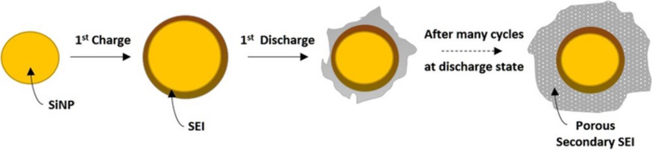
Figure 6. Effect of cycling on SEI growth over a Si nano particle.
Cui et al.150 have characterized the surface composition and morphology of the SEI formed on the silicon nano wires (SiNWs) in 1 M LiPF6 EC: DEC electrolyte using XPS and SEM. The authors150 have shown that high capacities can be obtained and maintained for several cycles and that irreversible capacity loss is not caused by lost or disconnected material, but rather is due to side reactions and SEI formation.
In the first charge to 0.5 V, the SEI layer is composed almost equally of hydrocarbons, PEO-type oligomers, LiF, LixPFy and LixPFyOz products, with smaller amounts of lithium alkyl carbonates and ethers. On the other hand, in the first charge to 0.1 V, the SEI surface consisted predominately of hydrocarbons and PEO-oligomers, indicating that more electrolyte was being reduced. Li2CO3 was also observed but no Li alkyl carbonates or ethers were observed, suggesting that these less stable products were transformed into Li2CO3. The amount of LiF and LiPF6 was lower than that at 0.5 V.
Finally, at the full charge to 10 mV, the SEI surface consisted mainly of Li2CO3 and LiF. The Li2CO3 is formed as a product of electrochemical reduction of the electrolyte, but the LiF is formed as a decomposition product rather than an electrochemical product. The morphology of the SEI was found to be voltage-dependent, with a thick layer consisting of large particles forming at low potentials, which partially dissolves and forms cracks as the potential is increased in the discharge. Improved cycling performance was observed when the voltage cutoffs were tuned to avoid large changes in SEI morphology, suggesting that the cycle life in SiNWs may rely a great deal on the SEI. This may be due to the enhanced reactivity of SiNWs as a result of the large surface area, as well as the composition of SEI products formed on the surface of the nanowire.150
A novel approach, based on three-dimensional (3D) growth of highly dense, mostly amorphous SiNWs on carbon-fiber-based open-structure conductive networks, was recently published. The electrolyte was 1M LiPF6 in EC/DEC (1:1) with 2% VC, to which fluoroethylenecarbonate (FEC) (15% by volume, Solvay-Fluor) was added.151 Several degradation mechanisms plausibly involved in the charge/discharge process of SiNW-based anodes were considered. It was concluded that the major reason for the capacity loss in the tested cells is an increase in cell impedance and not particle-to-particle and particle-to-current collector contact loss, disintegration or pulverization of the SiNWs. After 200 cycles, 80% of the SiNWs maintain their low rate capacity. The continuous SEI growth is caused by the reduction of the electrolyte salt and solvents leading to precipitation of solids, and drying out of the cell. This leads to capacity loss at high rates and suppresses the high rate capability of the anode. In addition, it was found that RSEI of the lithiated anode is smaller than that of the delithiated anode. This is mainly caused by the formation of a fresh, and thus lower-resistance SEI as a result of the expansion of the SiNWs and by the increase in their surface area. The low Qir, high efficiency and long cycle life of the SiNW anode are ascribed to two factors: the amorphous SiNW shell, and the nonparallel structure of the SiNWs leaving enough open space for electrolyte-reduction products and for the secondary porous SEI growth, without blocking the electrolyte path to the bulk of the anode.
The total SEI thickness, (including both the compact and the second porous layer) that was measured with the use of SEM, found to increase from 22 nm after the first cycle to 72 nm after the 11th cycles.151 In addition, it was found that all measured SEI parameters for the 3D SiNW anode - RSEI, ρSEI and SEI thickness - grow with cycle number. However, the growth of the secondary porous SEI was much higher than the growth of the compact SEI (measured by EIS). These observations point to the fact that the insufficiently stable SEI that leads to the intensive growth of the secondary porous SEI is the major factor in the observed capacity loss.151
P. Grey et al.152 investigated the SEI growth on nano silicon-carbon and carboxy methyl cellulose (CMC) composite electrode, which was formed from the reduction of a standard 1M LiPF6 in EC/DMC electrolyte and directly measured and quantified with the use of 7Li, 19F, and 13C ssNMR. In the first stage, the capacity loss is correlated with a growth of the SEI and increasing electrode tortuosity. The increased electrode density detected by FIB/SEM was ascribed to a combination of SEI formation on the silicon particles, particle agglomeration and SEI exfoliation from particle surfaces filling the pores of the electrode. In the second stage, the decrease in lithiation capacity was attributed to kinetics. The results support a model in which lithium-ion diffusion is severely limited by the increased electrode tortuosity throughout the bulk of the electrode.
L. Giebeler et al. studied the possible degradation mechanisms of silicon nanoparticles attached to a porous carbon-scaffold anode as a function of the electrolyte composition.153 A silicon-carbon anode was tested vs. a lithium-metal counter electrode in 1M LiPF6 in EC/DMC (1:1) (LP30 Selectilyte, BASF) without additives. Two major degradation mechanisms occur and both are attributed to the rapidly and continuously growing SEI: loss of electrical contact of individual silicon particles to the carbon scaffold and loss of ionic contact as a result of high film resistance which suppresses Li+ migration. After the addition of fluoroethylene carbonate (FEC), the film resistance decreases dramatically and the SEI growth rate is considerably lower. However, the growth of the SEI cannot be completely suppressed and eventually a thick SEI is formed, causing a loss of electrical contact between individual silicon particles. With the addition of VC, the growth of the SEI is nearly completely suppressed and the loss of electrical and ionic contact is prevented. However, the dense surface film results in low Li+ conductivity, hindering the use of high currents. The authors concluded that the VC additive for nano-silicon anodes clearly outperforms the FEC additive in terms of lifetime and efficiency owing to the formation of a very flexible surface film which survives the large volume changes. However, the surface film shows high film resistance to Li+ migration as a rate-determining step, likely due to the absence of defects in the film structure, making VC unfavorable for high-power applications. In contrast, the FEC-derived SEI shows less flexibility and reversibility compared to VC, but offers remarkable conductivity for Li+ ions, which are essential requirements for high power applications. The authors suggest that the polymeric properties of both, VC and FEC-derived SEIs are equal; however, in the case of FEC additional LiF nanocrystals are embedded within the surface film. These crystallites may cause defects in the homogeneous structure of the SEI, enabling enhanced Li+-ion conductivity, but at the expense of reversibility and cycle life. The compact inorganic nanocrystals decrease the flexibility of the surface film, which results in cracks during the volume changes of the silicon particles, which eventually causes a loss of electrical contact to the carbon. In the absence of any electrolyte additive, both loss of electrical and ionic contact are responsible for rapid degradation.
Meng et al.154 studied the manner in which FEC affects the evolution of SEI in terms of composition and morphology throughout electrochemical cycling in silicon nano-particle anodes. The authors concluded that the electrode, cycled in standard lithium-ion electrolyte with FEC additive, is covered with a uniform and stable SEI mainly at the first few cycles, while the SEI of the electrode cycled without additives immediately forms a porous and inhomogeneous SEI. The main reasons for better results are assigned to FEC decomposition products which eliminate the formation of a LixSiOy layer which leads to the immediate formation of a homogeneous, dense SEI.
Jung et al.155 showed that FEC can indeed improve the lifetime of silicon-carbon composite anodes but is continuously consumed during electrochemical cycling. FEC is capable of stabilizing cell performance only as long as it remains in the cell. Its total consumption causes a significant increase of the cell polarization leading to a rapid capacity drop. A new reductive decomposition mechanism for FEC-based electrolyte is proposed, which yields CO2, LiF, Li2O, Li2CO3, H2 and a partially cross-linked polymer. The authors showed that FEC nearly suppresses the reduction of any other electrolyte component, which suggests that the rate of FEC reduction is greater than the rate of reduction of EC and linear carbonates. Furthermore, the number of charge/discharge cycles over which silicon anodes can be stabilized by FEC is directly proportional to the total moles of FEC per gram of anode, rather than the FEC concentration in the electrolyte. The experiments were carried out with anode material comprising silicon nano particles (∼100 nm), vapor-grown carbon fibers and lithium polyacrylate (LiPAA) binder at 40:40:20 ratio. The FEC was added to 1 M LiPF6 EC:EMC 3:7 w/w electrolyte.
H. Song et al.156 compared the lithiation kinetics of nano and micro silicon anode particles. It was concluded that nanoparticle silicon benefits from smaller normalized resistance (Rp) and a thinner SEI layer compared to its micro-size counterpart. The results confirm the fact that the nano-sized anodes appear to be less dependent on the C-rate and show smaller values of Rp.
SEI on tin and tin oxide anodes
Nano-Sn, AlSi0.1 and Li4.4Sn powders were studied by EIS to determine the electrochemical kinetics and intrinsic resistance during initial lithium intercalation-extraction. It was shown that the SEI formed on the surfaces of the particles, together with their pulverization, are responsible for the high contact resistance.10 With the use of a high-speed-electroplating method (at currents above the limiting-current density), Peled and Ulus157–160 were able to produce two nanosize tin-antimony alloys. In Refs. 157,160 two sets of composite anodes - Sn65Sb18Cu17 and Sn62Sb21Cu17 - were produced. The weight ratio between the alloy and the PVDF-graphite material was 70:30. Graphite composite was added in order to enhance the resistance of the fragile porous structure of the alloy to cycling effects (volume changes, particle–to-particle break-off), and to sustain continuous electronic conductivity. The reversible capacity of the composite anode in a half-cell was 495mAh/g and the irreversible capacity was 25%. The capacity loss until cycle 35 was 0.48% per cycle, which is comparable to the capacity loss (0.51%) of a similar alloy with no graphite. In a tin alloy/LiCoO2 cell, the anode reversible capacity was 532 mAh/g, the irreversible capacity was 35% and the capacity loss (until cycle 20) was 0.9% per cycle. The dQ/dV curves of charge/discharge showed broadening of peaks between 300–1400 mV; this may indicate slower kinetics resulting from thickening of the SEI. The SEI thickening in turn, is due to active material disintegration and exposure of the active material to the electrolyte. As the cycle number increases, the SEI thickens and the migration of ions between particles becomes sluggish. A composite anode material, which contained a tin-antimony-copper (Sn60Sb20Cu20) alloy of 100nm particle size, graphite flakes with a particle size of 3–20 mm and PVDF as a binder was studied.10 As in the previous case, the main degradation mechanism of the composite anode is related to particle-to-particle break-off, and to the disconnection of particles from the current collector. A secondary degradation mechanism results from the thickening of the SEI layer with cycle number and its subsequent cracking, and is influenced by the electrolyte composition. XPS analysis indicates that after 30 cycles, tin and tin compounds were not identified in the SEI,10 even after 40 minutes of sputtering. This agrees with thickening of the SEI. The elemental depth profile of the electrode after six cycles, revealed that the concentration of Li decreased from 27 to 10 atomic %, and the concentration of F decreased from 17 to 9%. The oxygen content during the sputtering process was almost constant. Therefore, the excess of lithium over fluorine was attributed to Li2CO3 and Li2O. Only low concentrations of hydrocarbons and oxygen-containing polymeric compounds were detected in the SEI. In addition, the LiF content in the SEI increases with cycle number from 20 to 48%. Such SEI composition with high concentrations of inorganic salts and low content of polymeric compounds is expected to be followed by increased brittleness and possible break-off on cycling. It was concluded that that the degradation mechanism of the active material in tin-based alloys involves particle-to-particle separation, and the thickening and cracking of the SEI with increasing cycle number.10
V. Winkler et al.161 investigated the chemical composition of the SEI formed in LiTFSI-based electrolytes using VC and FEC as performance-improving additives for nano-particulate SnO2 film anodes. During the first discharging cycle of SnO2 anodes, metallic tin and lithium oxide are formed and are responsible for Qir. Subsequent charging and discharging correlate to lithiation/delithiation reaction in a kind of alloying/dealloying of tin. The study showed the existence of a high surface reactivity of nanoparticulate SnO2 electrodes leading to the formation of a significant amount of oxidized carbon surface species, mainly Li2CO3, already at the initial cycling. This irreversible consumption of lithium for SEI forming is the main reason for low coulombic efficiencies. The high surface reactivity of SnO2 leads to preferred decomposition of the main electrolyte components, EC and DMC. This complicates the identification of VC-related SEI species via XPS. Despite this, the FEC additive could better influence the SEI composition, resulting in further improvement of the cycling properties as compared to those of the pure LiTFSI or LiTFSI+VC electrolytes.161
SEI on lithium anodes in lithium/sulfur batteries
Capacity fading of the lithium/sulfur battery on cycling results from at least four processes: increase of SEI thickness and SEI resistance on the lithium anode, loss of cathode capacity (precipitation of sulfur species outside the cathode), agglomeration and thickening of core-shell sulfur species and increase in cell impedance as a result of reduction of the electrolyte. On discharge, two transport processes (diffusion and migration) contribute to the transport of polysulfide anions to the lithium anode. This leads to an increase in the concentration of polysulfides near the anode. On the other hand, during charge, the polysulfide concentration near the anode decreases. The reactions of polysulfides with lithium are complex; short ones are expected to cause precipitation of Li2S and Li2S2 as lithium-corrosion products, while long polysulfides may partially dissolve Li2S and Li2S2 particles from the SEI. Reaction of the anode with PSs and with the electrolyte may lead to the thickening of the primary and the secondary SEI. However, it was recently found that both RSEI and SEI thickness change very little on cycling (Table I).28,162
Table I. Lithium sulfur battery (1 cm2 electrode area, coin cell), effect of cycling on EIS parameters.28,162
| Cycles | RSEI [Ω] | CSEI [F] | L*SEI [nm] | σ [Ω−1S−1] |
|---|---|---|---|---|
| 19 | 79 | 0.8E-6 | 8.4 | 28 |
| 35 | 68 | 0.7E-6 | 9.5 | 53 |
| 205 | 75 | 0.8E-6 | 9.1 | 217 |
Table I shows that the major parameter responsible for the fade of capacity is the decrease of the effective diffusion constant of lithium in the secondary porous SEI (deduced from the increase of Warburg parameter, D ∝σ− 2). SEI resistance may increase with the increase of the PS concentration in the electrolyte, for example at the end of charge. The soluble polysulfides cause a shuttle reaction, which results in loss of active material, an accelerated failure of the lithium anode and reduction of the faradaic efficiency of the battery.164
Xiong et al.163 used 1M LiN(CF3SO2)2 (LiTFSI) in 1,3-dioxolane (DIOX) and 1,2-dimethoxyethane (DME, 1:1 v/v) mixed solvents in a symmetrical coin cell consisting of two lithium-metal electrodes, to study the SEI on the lithium anode in a lithium/sulfur battery. The authors found that the surface film on the lithium electrode stabilizes after a certain number of cycles. However, after 105 cycles, the resistance value increases, demonstrating the disruption of the surface film. The symmetrical cell cycled in the electrolyte solution with polysulfides results in a stable potential, which means that the system has a stable interface between the lithium electrode and the electrolyte solution. Furthermore, SEM images show that the decomposition of lithium salt on the lithium electrode can be prevented by the surface film formed with polysulfides, which is attributed to the special structure of the film. Based on the XPS spectra and depth profiling, the authors assumed that the surface film consists of two sub-layers - a top layer composed of the products of electrolyte-solution decomposition and a bottom layer of lithium sulfide.163
Zheng et al.164 found that anode consumption accelerated by a corrosive polysulfide solution, critically determines the Li/S cell performance. The ionic liquid (IL) N-methyl-N-butylpyrrolidinium bis(trifluoromethylsulfonyl)imide (Py14TFSI) has been employed to modify the properties of the SEI formed on the lithium-metal surface in Li/S batteries. It was found that the IL-enhanced formation of a passivating film on the lithium-anode surface exhibits very different morphology and chemical composition, effectively protecting lithium metal from continuous attack by soluble polysulfides. During storage, in contrast to the common lithium-ion electrolyte cells, in cells with the IL-containing (50% IL) electrolyte, the cell impedance is much more stable, despite a slight increase in the total resistance during the first few days. To modify the SEI on the Li-metal surface, IL Py14TFSI has been incorporated as a co-solvent into the conventional electrolyte. When 75% IL-containing electrolyte was used in the Li/S battery system, the electrochemical performance was significantly improved. The authors concluded that the ionic liquid facilitates the formation of a stable SEI of improved quality. This dense SEI effectively prevents the continuous penetration of soluble polysulfides to the surface of the anode, which slows its rapid corrosion and eliminates the increases in the impedance.164 EIS measurements of a cycled lithium/sulfur cell reveals that, in some cases, RSEI almost does not change during the first 200 cycles. It was found that both the type of the cathode binder and the type of the polysulfide barrier layer affect the performance and the fading rate of the battery. An optimized combination of a binder and a barrier layer yield an initial capacity of 1400 mAh/g (per sulfur mass), over 99.5% coulombic efficiency and close to 1000 cycles. Capacity fading results from the increase in both RSEI and RCT and the decrease in D during prolonged cycling. D decreases as a result of several processes, including partial blocking of the cathode surface, precipitation of electrolyte reduction products on the anode (as a secondary SEI10) and into the separator.
Cathodic SEI
According to Novak et al.,165 a protective film similar to SEI is also reported for cathode materials such as LiMn2O4, LiCoO2, and LiNiO2. It was shown (Aurbach166) that the cell impedance, of aged cells, originates mainly from the transition metal oxide cathode. This indicates the possibility of the formation of a surface film on the oxide.166 As in the case of graphite anode materials, the surface film at the electrode/electrolyte interface of the oxides leads to an irreversible ''charge loss''. Different parameters may have an impact on the formation and properties of this surface film, including; The type of the cathode material, the solvents, the conducting salts used for the production of the electrolyte and electrolyte additives.
Conclusions and Perspective
The anode/electrolyte interphase (SEI) plays a key role in alkali–metal, alkali-metal ion and alkaline-earth batteries. It was found that ionic migration through the SEI is the rate-determining step for many systems. In this case, the Tafel slope (b) is a linear function of the thickness of the SEI. Under OCV conditions, the increase in the thickness of the SEI follows a parabolic law with respect to the time of storage. The study of SEI properties in future systems including lithium/sulfur, lithium/air, sodium, sodium-ion and calcium batteries is in its early stage. A combination of a variety of analytical tools, including dilatometry, STM, AFM, XPS, EDS, SEM, XRD, QCMB, FTIR, NMR, EPR, TOF SIMS, Raman spectroscopy, AC-impedance measurements and DSC is used in order to gain a comprehensive characterization of the processes occurring at the anode/electrolyte interphase.
Molecular dynamics (MD) and density-functional theory (DFT) simulation methods have been used to gain an understanding of the relationship between the SEI layer and the electrolyte. The use of Ab-initio molecular dynamics (AIMD) has extended MD capability by combining the Schrodinger wave equation with Newton's equations.
The SEI is formed by parallel and competing reduction reactions and thus its composition depends on i0, η and the concentrations of all the electroactive materials in the electrolyte. Close to the electrode side, the SEI consists of fully reduced (thermodynamically stable) anions such as F−, O2−, S2− and other elements like As, B, C (or their lithiated compounds). The outer part of the SEI (near the solution) consists of partially reduced materials like polyolefins, polyTHF, Li2CO3, LiRCO3, R-O-Li, LiOH, and LiF, LiCl, Li2O, etc. TOF SIMS measurements provide direct evidence for the existence of polymers in the basal SEI.
The true lateral size of the micro domains in HOPG and graphite electrodes, is about or less than 1 micron. Since the SEI consists of a mosaic of heteropolymicrophases, the contribution of grain boundaries must be considered. The equivalent circuit of the SEI is extremely complex and should be represented by a very large number of series and parallel distributions of RC elements, reflecting bulk ionic conductivity and grain-boundary phenomena, aside from the Warburg element.
For carbon anodes, the exchange-current density of the reduction reactions also depends on the surface properties of the electrode (content of impurities, surface chemistry and surface morphology). The surface chemistry and morphology of the SEI vary with the ratio of basal-plane to edge-plane areas of carbons. We have suggested that the carbon matrix has a more marked effect on the composition and thickness of the SEI than does the nature of the electrolyte. Mild oxidation of graphite was found to improve anode performance. Improvement was attributed to the formation of SEI chemically bonded (CB-SEI) to the surface carboxylic and oxide groups at the zig-zag and armchair faces, better wetting by the electrolyte and to accommodation of extra lithium at the zig-zag, armchair and other edge sites and nano voids. Graphite-surface modification by silylation and the creation of the core-shell-structured carbon composite look promising for the enhancement of electrochemical performance. In lithium-ion batteries, with carbonaceous anodes, QIR can be lowered by decreasing the true surface area of the carbon, using pure carbon and electrolyte, applying an optimal charge protocol at the first charge (system-dependent) and by using proper electrolyte component combinations and SEI precursors. In some systems, increasing charging rates for fast SEI formation, results in incomplete, non-uniform, electrochemically unstable layers or deposits, thereby lowering cell efficiency, durability and safety. Similarly, insufficient electrolyte wetting leads to a low-quality SEI layer, inactive surface area, and/or premature degradation of cell performance. EIS measurements of a cycled lithium/sulfur cell reveal that, in some cases, RSEI almost does not change during the first 200 cycles. Capacity fading results from the increase of both RSEI and RCT and the decrease in diffusion coefficient (D) during prolonged cycling.162 D decreases as a result of several processes, including partial blocking of the cathode surface, precipitation of electrolyte reduction products on the anode (as a secondary SEI) and into the separator. In this system, reducing electrolyte reduction by the anode is essential for achieving a long cycle life.
An understanding of SEI-related phenomena is crucial for the development of safer and better SEI batteries. Today we have a good understanding of SEI-formation processes, kinetics of SEI electrodes and SEI growth in common systems, mainly lithium-ion and some lithium-metal batteries. However, in general, actual SEIs do not yet seem to have optimal properties; they continue to grow over repeated charge/discharge cycles and over long storage and dissolve at elevated temperatures creating dangerous situations and for silicon anodes they do not provide the required durability. Intensive research is currently ongoing to improve SEI properties and to develop an artificial SEI. Progress is slowly being made in increasing the durability of lithium ion and lithium sulfur batteries and silicon based anodes.