Abstract
In this paper, we report on our recent efforts to develop a biomass-depolarized electrolyzer for efficient production of H2. Electrochemical oxidation of lignin-rich biorefinery waste streams can occur at lower overpotentials than those required for O2 evolution, which leads to potentially lower-voltage electrolyzer operation that could lower the energy requirements for electrolytic production of H2. In addition, the anode product stream may possess economic value greater than that of O2, which could provide an additional revenue stream for electrolytic production of H2.
Export citation and abstract BibTeX RIS

This is an open access article distributed under the terms of the Creative Commons Attribution 4.0 License (CC BY, http://creativecommons.org/licenses/by/4.0/), which permits unrestricted reuse of the work in any medium, provided the original work is properly cited.
Electrolysis of water is a well-known and an established process for the generation of H2. With the advent of proton exchange membranes (PEMs), research and development efforts into water electrolysis increased a great deal1 and several commercial systems have been developed.2,3 With the maturation of PEM water electrolyzer technology, efforts today often focus on economic feasibility,4 which has not been achieved for water electrolysis yet at large scale. Despite technological advances and development of some commercial systems, PEM water electrolysis still has two major drawbacks: 1) oxygen evolution reaction (OER) kinetics are slow in acidic solutions, which leads to high overpotentials and high energy requirements and 2) expensive noble metals are typically required due to stability issues in acidic media under anodic conditions.
To obviate the outstanding issues inherent in PEM water electrolysis, considerable research efforts in recent years have focused on the development of anion exchange membrane (AEM) water electrolysis systems.5 In alkaline media, the kinetics of the OER are somewhat improved over acid media, and many transition metals are stable under anodic conditions in alkaline solution, potentially eliminating the need for expensive noble metal electrocatalysts. Many research efforts related to these systems have focused on the development of the AEM, due to typically poorer chemical and mechanical stability and lower ionic conductivity than PEMs.6–8 It is expected that AEM electrolyzers could come close to the performance observed in PEM electrolyzers.9
At any rate, still-sluggish OER kinetics often limit electrolyzer performance. This limitation leads to two issues with current electrolyzer technology: 1) high energy requirements to overcome sluggish OER kinetics adds to the financial burden of electrolytic production of H2 and 2) the anode product stream (O2) has little economic value, meaning that much of the energy expended for electrolytic production of H2 results in a fairly useless product.
Researchers for many years have been looking for ways to overcome the challenges with water electrolysis. Depolarization of the anode, replacing the OER with a less energy-intensive reaction, has been investigated as a way to lower the energy requirements for H2 production. Several systems, including SO2-depolarized electrolysis,10 coal-depolarized electrolysis,11 electro-oxidation of glycerol12 and biomass-depolarized electrolysis13 have been proposed.
More closely related to the work presented here, in the early 1990s Lalvani and Rajagopal described their efforts toward generating H2 at the cathode as a co-product of lignin oxidation at the anode of an electrochemical cell.14,15 They observed hydrogen evolution at 1.24 V vs. SHE, with the hydrogen production rate increasing with temperature. Several other biomass electrolysis processes have been described in the literature.16,17 More recently, another research group has published work on a polymer electrolyte membrane-based lignin electrolyzer employing a Pt-Ru anode electrocatalyst operated at temperatures approaching 90°C.18
In any event, the key to biomass-depolarized electrolysis is the ability to electrochemically oxidize the biomass at relatively low overpotentials (compared to the OER). Electrochemical oxidation of lignin, for example, has been described extensively in recent years,19–22 with focus either on identifying oxidation products or developing more efficient anode electrocatalysts. This group has reported its work to develop NiCo electrocatalysts for the conversion of lignin.23
In this paper, we report on our efforts to develop a biomass-depolarized electrolyzer operating at room temperature and atmospheric pressure for the production of H2. We also explore the possibility of operating the electrolyzer at higher temperatures as a way to increase the reaction rate. The H2 generated at the cathode of this reactor is one of two product streams that have been investigated as part of a Department of Energy-sponsored project focused on electrochemical conversion of lignin-rich streams produced during the biorefining process. The other potential product stream is that of the anode (the electrochemically oxidized biomass), the analysis and valuation of which is beyond the scope of the current communication.
Experimental
NiCl2•6H2O, CoCl2•2H2O, ethylene glycol, sodium citrate, and NaOH were purchased from Sigma-Aldrich and used as received. Anion exchange membranes (FAA-3) were purchased from Fumatech and stored in a 1 M NaOH solution prior to use. Carbon cloth electrodes loaded with 2 mg/cm2 Pt black on porous gas diffusion layers (GDL) (Spectracarb 2050A-0550) were purchased from the Fuel Cell Store. Biorefinery waste was provided by the Integrated Biorefinery Research Facility (IBRF) operated by the National Renewable Energy Laboratory (NREL).
To prepare 1 g of 1:3 NiCo/TiO2 electrocatalyst, 0.61 g NiCl2•6H2O and 0.99 g CoCl2•2H2O as electrocatalyst precursors were added to 75 mL ethylene glycol under stirring. Next, TiO2 nanoparticles with an average particle size of 21 nm were added to this solution to achieve 60% by mass metal loading in the electrocatalysts. The mixture was heated to 80°C under 300 rpm stirring (with a magnetic stir bar) for 2 h. Subsequently, the pH of the mixture was adjusted to 10 by addition of 1.6 g NaOH. Approximately 0.25 g sodium citrate dihydrate as a reducing agent was added to the mixture. Afterward, the temperature was raised to 180°C and was held under reflux for 2 h. After synthesis, the electrocatalysts were filtered, washed, dried, and ground into a powder. A mass of 0.5 g electrocatalyst was suspended in 65 mL ethanol solution containing 0.16% w/w fumion ionomer as a binder.
The electrocatalyst was characterized by X-ray diffraction (XRD) spectroscopy and Brunaur-Emmett-Teller (BET) analysis. The powder XRD pattern of the electrocatalyst was obtained on a Rigaku Ultima IV device for identifying the approximate crystallite sizes and phase structure of the nanoparticles. The XRD diffraction pattern was obtained in the 2θ range of 20–80° at a scan rate of 3°/min. The average crystallite size of the nanoparticles was estimated using Scherrer's equation. The specific surface area of the electrocatalyst was measured by N2 adsorption at 77 K based on the BET method using a Micromeretics ASAP 2010 instrument. The average size of the nanoparticles was measured from the BET surface area by assuming a spherical shape from dBET of 6000/ρSBET, in which SBET is the BET surface area (m2/g), dBET is the average nanoparticle diameter (nm), and ρ is the skeletal density (g/cm3).
The H2 generated at the cathode was detected by a gas chromatograph (Agilent Technology 7890B) equipped with an NGA column and a thermal conductivity detector (TCD). Helium at a flow rate of 0.5 mL/min was used as the carrier gas. The column temperature was kept at 60°C for 11 min and then raised to 200°C at the rate of 36°C/min, and was held at 200°C for 5.1 min. The inlet and detector temperatures were 250°C.
The lignin-rich biomass solutions were prepared in the following way: The solid biomass (essentially the lignin cake obtained by the IBRF from the biorefinery filter press) was dispersed in distilled water and kept under stirring for 2 days. Then the slurry was filtered with a 25-micron sieve to separate the large particles. The remaining mixture was dried at room temperature for several days and further dried at 75°C in a laboratory oven. Afterward, different amounts of the solid sample were added to 1 M NaOH solutions to reach desired (10–100 g/L) concentrations of lignin. After stirring the solution for a day, the solution was centrifuged to separate the solid insoluble part.
The anode was prepared in the following way: 1:3 NiCo/TiO2 suspended in the fumion/ethanol solution was spray-coated onto the carbon paper GDL by means of a hobby spray gun. Spray-coating of the electrocatalyst continued until a loading of 8 mg/cm2 was achieved.
The 10 cm2 electrochemical reactor used in this study was a single cell purchased from Fuel Cell Technologies, Inc (Figure 1). The cell was constructed in the typical way, such that the 2 mg/cm2 Pt-loaded carbon cloth and porous GDL loaded with 1:3 NiCo/TiO2 were oriented with the electrocatalyst layer facing the anion exchange membrane. A symmetric 0.68 mm-wide flow channel with a length of 66 cm was machined into the graphite flow blocks on either side of the cell.
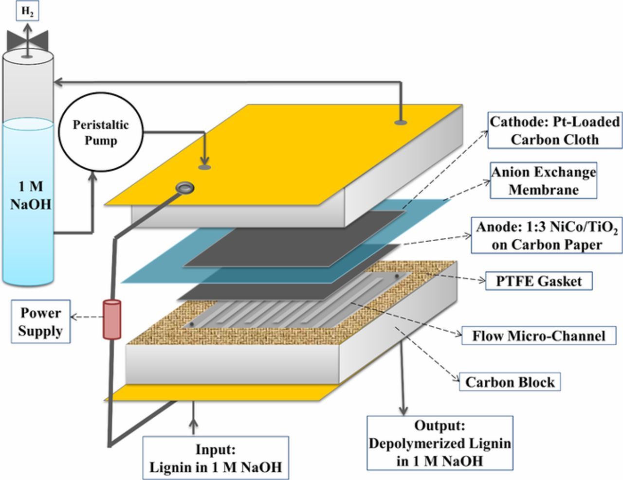
Figure 1. Schematic of the 10 cm2 continuous electrochemical reactor for lignin depolymerization with cogeneration of H2.
Lignin dissolved in NaOH was introduced into the anode side channel and NaOH solution was fed into the cathode side channel with the flowrates of 1 and 2 mL/min, respectively, using peristaltic pumps. The residence time of the lignin solution was 18 s to avoid complete oxidation of the biopolymer. The H2 generated at the cathode was separated from the liquid and the NaOH solution was recycled. H2 production was measured at the cathode with a bubble flowmeter and the volume of O2 generated over time at the anode was measured by water displacement. The cell voltage was controlled by a power supply (Agilent E3631) and the current at each applied cell voltage was monitored by the device. The temperature of the cell was controlled by a built-in heating rod and a thermocouple inside the cell endplate, which were attached to a PID temperature controller.
Results and Discussion
Figure 2 has the XRD patterns of 1:3 NiCo/TiO2 electrocatalyst. The notable peaks in the XRD pattern correspond to the anatase and rutile structures of TiO2, Ni, Co, CoO, and Co(OH)2, which are indexed based on JCPD (Joint Committee on Powder Diffraction) standards; the file numbers are included in Figure 2. The presence of CoO may be due to the high reactivity of the cobalt nanoparticles with oxygen.24 The presence of cobalt hydroxide could be due to a partial reduction of Co(OH)2 during the synthesis process.25,26 The average crystallite size of the electrocatalyst is 15.7 nm. The surface area is 130 cm2/g and the average size of the nanoparticles is 6.5 nm by BET analysis.
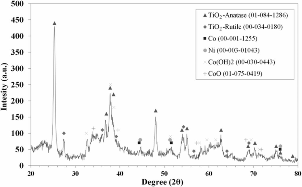
Figure 2. XRD patterns of 1:3 NiCo/TiO2 synthesized by the wet impregnation method.
There are two possible major reactions which may occur at the anode of the biomass-depolarized electrolyzer: 1) lignin oxidation, which is the desired reaction and 2) the OER, which is an undesired reaction. At some cell voltages, these two reactions may compete with one another. We expect lignin oxidation to occur at lower potentials than the OER, which is the driving force behind the idea of biomass-depolarized electrolysis. High-rate generation of O2 at the electrolyzer anode would consume energy that would better be used for lignin oxidation and represents an energy-intensive process that should be avoided. However, it may not be possible to completely eliminate the OER at all cell voltages, because as the anode overpotential increases, the OER may compete with lignin oxidation. Therefore, we can view the OER as a competing reaction, and its importance should be evaluated.
Figure 3a is the current density as a function of operating cell voltage for water (triangle markers, ˗˗˗ ·· ˗˗˗ line style) and biomass-depolarized (circle markers; solid line) electrolysis at 25°C. At this temperature, the observed current density for biomass-depolarized electrolysis is greater than the current density for water electrolysis (i.e., in the absence of lignin) up to slightly greater than 1.5 V. This result indicates that at lower cell voltages, electrochemical lignin oxidation competes favorably with the sluggish OER, which likely requires greater overpotential to proceed at an appreciable rate.
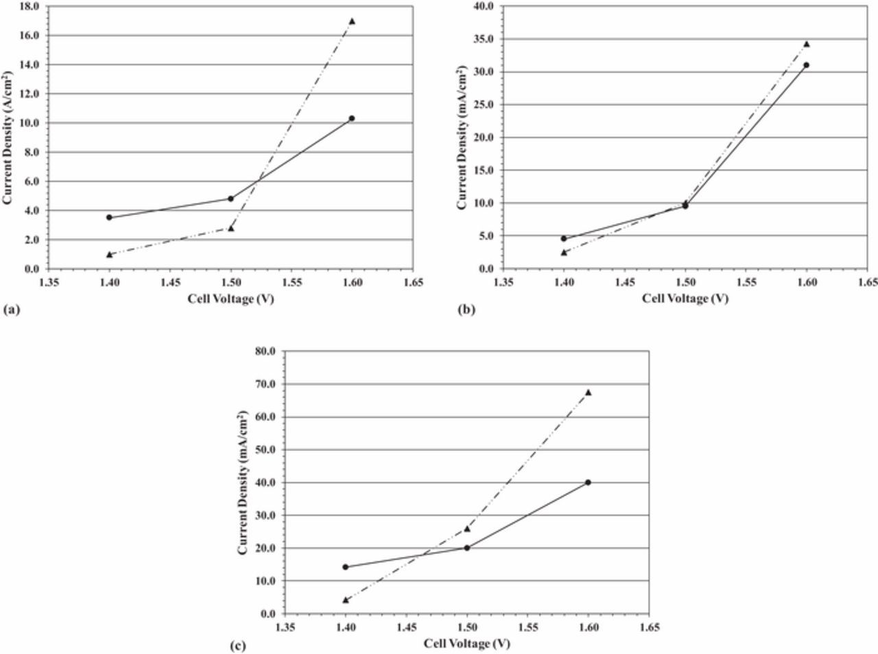
Figure 3. (a) Current density as a function of cell voltage for water electrolysis (triangle markers; ˗˗˗ ·· ˗˗˗ line style) and biomass-depolarized electrolysis (circle markers; solid line) at 25°C. (b) Current density as a function of cell voltage for water electrolysis (triangle markers; ˗˗˗ ·· ˗˗˗ line style) and biomass-depolarized electrolysis (circle markers; solid line) at 40°C. (c) Current density as a function of cell voltage for water electrolysis (triangle markers; ˗˗˗ ·· ˗˗˗ line style) and biomass-depolarized electrolysis (circle markers; solid line) at 60°C.
Similar trends can be observed at 40°C and 60°C, as can be seen in Figures 3b and 3c, respectively. It is interesting to observe that the cell voltage at which water electrolysis current density becomes greater than biomass-depolarized electrolysis current density decreases at successively higher temperatures. This behavior could be caused by the rapidly increasing OER kinetics at elevated temperatures versus the relatively small increases in lignin oxidation kinetics at those same temperatures.
These results could indicate that lignin oxidation is thermodynamically more favorable than oxygen evolution (meaning that lignin oxidation occurs at an appreciable rate at potentials lower than those required for oxygen evolution). In other words, in water electrolysis (in the absence of lignin at the anode), the only electrochemical reaction that occurs is the OER; at lower cell voltages, the overpotential is not sufficient to drive the sluggish OER at an appreciable rate. With the addition of lignin, on the other hand, there is now another reaction at the anode, that of electrochemical conversion of lignin. At the same low cell voltages, the overpotential is sufficient to drive electrochemical conversion of lignin at a measurable rate. However, at cell voltages greater than about 1.5 V, the water electrolysis current density is greater than the biomass-depolarized electrolysis current density, which may indicate that the OER is more kinetically facile than lignin oxidation. This trend is observed over all temperatures and indicates that between the two competing reactions, the OER is kinetically favored at cell voltages greater than 1.5 V, regardless of temperature. It must be noted that in biomass-depolarized electrolysis, unlike water electrolysis, a low OER efficiency is desirable. Any current that goes toward the OER in biomass-depolarized electrolysis generates an undesirable product (oxygen), instead of the desirable product (lignin oxidation products). In Figures 3a–3c, the observed current density for biomass-depolarized electrolysis (circle markers; solid line) is the total current density, which indicates the rates of both lignin oxidation and the OER. To fully understand the implication of the competing OER with lignin oxidation, we need to measure the rate (and hence, the efficiency), of the OER, understanding that low OER efficiencies are desirable in biomass-depolarized electrolysis.
We compare the faradaic efficiency for the OER in the two systems in Figure 4. The trend is immediately apparent. To help guide the reader's attention, the top three curves (starting at an OER faradaic efficiency of 50–60%) are those for water electrolysis (in the absence of lignin). The bottom three curves (starting at an OER faradaic efficiency of 0%) are those for biomass-depolarized electrolysis. The data are generated at 25°C (˗˗˗ · ˗˗˗ line style), 40°C (solid line) and 60°C (- - - line style). The differences in OER faradaic efficiency between water and biomass-depolarized electrolysis are quite large. For example, at 1.4 V, the OER faradaic efficiency for water electrolysis varies between about 50% at 25°C and 61% at 60°C. By contrast, the OER faradaic efficiency for biomass-depolarized electrolysis at 1.4 V is essentially 0% at all temperatures, indicating that lignin oxidation occurs at lower potentials than the OER and consumes essentially all of the current at this cell voltage. The reader is referred to Figure 3c, where the current density for biomass-depolarized electrolysis at 60°C was approximately 14 mA/cm2, even though no oxygen evolution was observed (0% OER faradaic efficiency). The likely reaction occurring under those conditions is lignin oxidation. Indeed, the general trend observed in Figures 3a–3c is that the biomass-depolarized electrolyzer current density is higher at all temperatures at 1.4 V, even though we observe no oxygen evolution at that cell voltage.
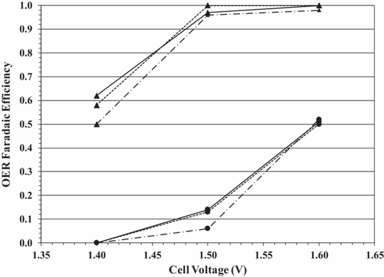
Figure 4. OER faradaic efficiency as a function of cell voltage for water electrolysis (solid triangle markers) and biomass-depolarized electrolysis (solid circle markers) at 25°C (˗˗˗ · ˗˗˗ line style), 40°C (solid line) and 60°C (- - - line style).
As the cell voltage increases at all temperatures, so too does the OER faradaic efficiency. For the case of water electrolysis, the OER faradaic efficiency is very nearly 100% at about 1.5 V, while for biomass-depolarized electrolysis, the efficiency is between 5% and 15% at 1.5 V, depending on temperature. At 1.6 V, however, the biomass-depolarized electrolyzer OER faradaic efficiency is about 50%, a significant increase over that observed at 1.4 V, but still about half that of the water electrolyzer. In other words, as the biomass-depolarized electrolyzer cell voltage is increased, the system behaves more like a water electrolyzer, which is undesirable.
These results have potential implication for electrolyzer operation. As expected, the current density increases in both water and biomass-depolarized electrolysis as the cell voltage is increased (Figures 3a–3c). In the case of water electrolysis, this increase is essentially the result of the increase in the OER rate. In biomass-depolarized electrolysis, on the other hand, both the rates of lignin oxidation and the OER increase with increasing cell voltage. In that case, we are left with two competing reactions: lignin oxidation (favored) and the OER (not favored). Therefore, while increasing the cell voltage increases the rate of lignin oxidation, it also increases the rate of the OER, likely making the overall process less energy-efficient.
It should be noted, however, that while the rate of the OER does indeed increase with cell voltage in biomass-depolarized electrolysis, its increase is offset somewhat by the increase in the lignin oxidation rate, so that its faradaic efficiency remains about half that of water electrolysis, even at 1.6 V. Thus, even at high cell voltages, there is still likely an appreciable rate of lignin oxidation (at least half of the current goes toward lignin oxidation), which holds promise for any commercial system eventually developed utilizing this technology.
The lignin concentration is also an important parameter to biomass-depolarized operation, although we have not observed changes in the open circuit voltage as a function of concentration. One can observe a maximum in the current density at 1.4 V and 1.5 V as a function of lignin concentration in Figure 5. The maximum is most likely due to the relative rates of the competing reactions, lignin oxidation, and the OER, in the following way: At lower cell voltages (below 1.6 V), there is not sufficient energy to sustain the OER at a high rate, and lignin oxidation dominates; the observed current density is due primarily to this reaction.
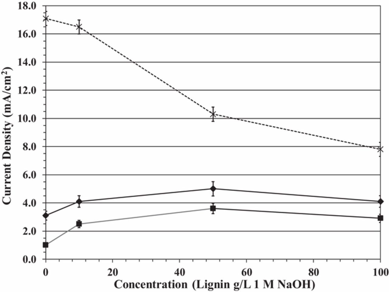
Figure 5. Current density as a function of lignin concentration at 1.4 V (solid square makers, bottom solid line), 1.5 V (solid diamond markers, middle solid line) and 1.6 V (X markers, top dotted line).
Increasing the lignin concentration increases the rate of this reaction, as expected. However, at higher lignin concentrations (above 50 g/L), lignin may partially clog GDL pores or block active electrode sites, reducing the reaction rate. At higher cell voltages (above 1.5 V) where the OER dominates, any lignin in solution reduces the overall reaction rate. This reduction in the overall reaction rate is likely caused by limited kinetics, even though lignin oxidation may be favored thermodynamically (i.e., occurring at a lower potential) than the OER. Its occurrence reduces the overall reaction rate for biomass-depolarized electrolysis versus water electrolysis at cell voltages where the OER would be driven at an appreciable rate.
For example, at 1.6 V the current density for water electrolysis (no lignin in solution) is about 17 mA/cm2. Adding lignin to the solution (biomass-depolarized electrolysis) reduces the current density to about 11 mA/cm2 at 50 g/L concentration because the slower lignin oxidation reaction competes with the OER, which is the kinetically-favored reaction at this voltage. Thus, there is likely some trade-off in operation of the biomass-depolarized electrolyzer at room temperature: intermediate lignin concentrations and cell voltages below 1.6 V maximize lignin oxidation and minimize the rate of the OER.
During water electrolysis, we observe a decrease in the current density of approximately 27% over 6 days at 1.4 V. This decrease may be attributed to electrocatalyst deactivation or poisoning by oxidation products.27 The flow rate of H2 was measured over the current density range of 3.5 to 30 mA/cm2 in the 10 cm2 cell after 24 h of reactor operation at 1.4 V and 50 g/L lignin concentration (Table I). We observe an average faradaic efficiency of 99% for the HER. In addition, the electrical energy consumed by the electrolyzer and energy efficiency based on the electrical energy stored as H2, in terms of the higher heating value (HHV) at each current density are reported in Table I.
Table I. Rate of H2 generation from 50 g/L lignin electrolysis and energy consumption of the continuous electrochemical reactor at room temperature and pressure. The data was collected after 24 h using 8 mg/cm2 1:3 NiCo/TiO2 and 2 mg/cm2 Pt as anode and cathode electrocatalyst, respectively.
| Average Cell | Current density | Measured flowrate | faradaic efficiency | Energy density | Energy efficiency |
|---|---|---|---|---|---|
| voltage (V) | (mA/cm2) | of H2 (mL/min) | of H2 evolution | (kWh/kg H2) | (HHV)* (%) |
| 1.40 | 3.5 | 0.25 | 0.95 | 39.5 | 100 |
| 1.51 | 5.0 | 0.37 | 0.98 | 41.3 | 95 |
| 1.60 | 10.0 | 0.74 | 0.99 | 43.4 | 91 |
| 1.64 | 15.0 | 1.12 | 1.00 | 44.0 | 90 |
| 1.67 | 20.0 | 1.49 | 1.00 | 44.8 | 88 |
| 1.72 | 30.0 | 2.26 | 1.01 | 45.7 | 86 |
*The energy efficiency was calculated as follows:
 where
where  is the mass of H2 produced in one hour at each current density and
  is the higher heat value of H2 gas, which is 141.79 MJ/kgH2 at 25°C and 1 atm and E (MW•h) is the electrical energy consumed at each current density.
Table I reports the energy efficiency for H2 generation. By increasing the cell voltage from 1.4 V to 1.72 V, energy requirements increase from 39.5 to 45.7 kWh/kg H2, corresponding to a 14% decrease in energy efficiency. These results have implications for biomass-depolarized electrolysis. While biomass can be oxidized at lower potentials than oxygen evolved, the current density is relatively small, leading to a low rate of hydrogen production, albeit at relatively low energy requirements. It would be likely that large biomass-depolarized electrolyzers would have to be constructed, and that some value from the anode product stream would be needed to offset the capital cost.
In any event, the hydrogen that is generated by the biomass-depolarized electrolyzer is quite pure. Figure 6 is the gas chromatogram of the gas collected from the electrolyzer cathode during biomass-depolarized electrolysis. The H2 peak is at 1.5 min and two minor peaks, corresponding to O2 and N2, are detected at 7.6 and 8.2 min, respectively. Analysis indicates a H2 purity of about 97.6%. The N2 and O2 impurities are air-like mixtures, which possibly enter during sample collection.
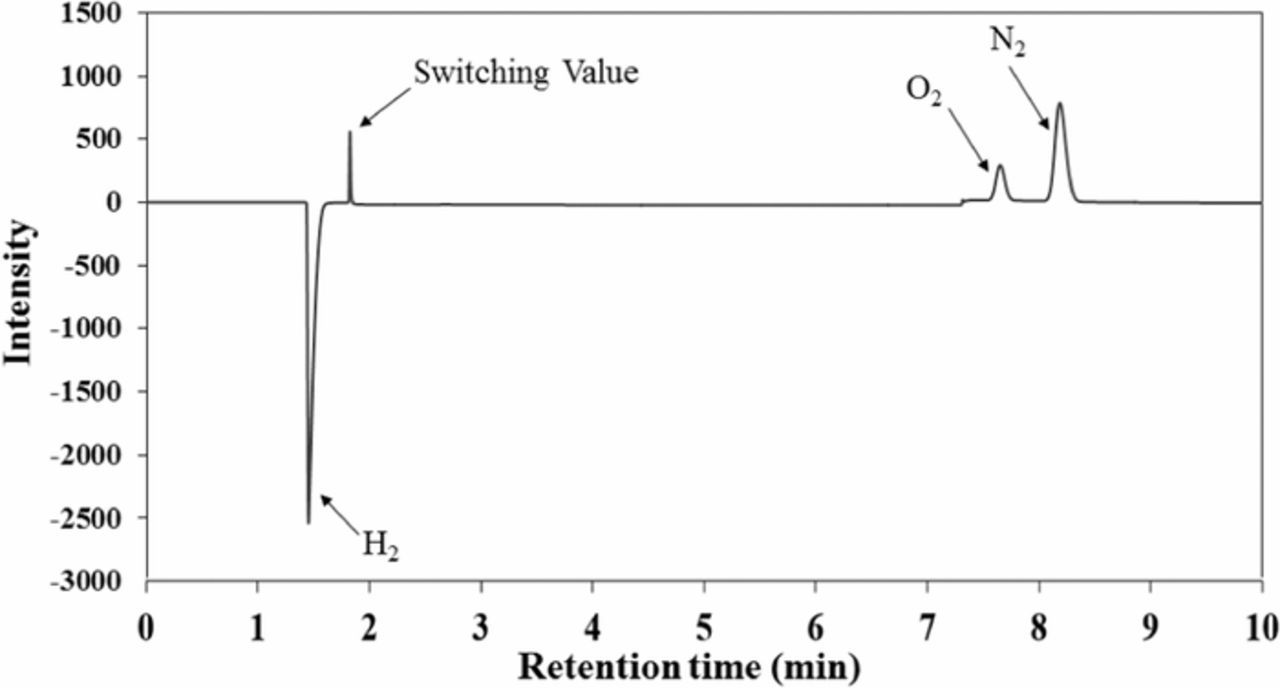
Figure 6. GC-TCD chromatogram of the generated gas at the cathode during oxidation of 50 g/L of lignin in 1 M NaOH at the anode.
Conclusions
We have developed a biomass-depolarized electrolyzer utilizing inexpensive non-precious metal anode electrocatalysts and lignin-rich biorefinery-generated biomass dissolved in NaOH as the analyte. This system can generate H2 at voltages lower than those typically required for water electrolysis, albeit at relatively low current densities. As the cell voltage increases, so does the current density (but so too does the rate of the OER, which is an undesired reaction in this system). In any event, this biomass-depolarized electrolyzer has been shown to generate H2 at room temperature and atmospheric pressure; increasing the temperature increases the rate of reaction. If the biomass oxidation products are found to possess economic value, then the biomass-depolarized electrolyzer could provide additional revenue for electrolytic production of H2. Future work should focus on estimating the economic value of the anode product stream.
Acknowledgments
The authors would like to acknowledge the Bioenergy Technologies Office (BETO) at the U.S. Department of Energy for funding this research (Award DE-EE0007105). The biomass used in this research was provided by the Integrated Biorefinery Research Facility operated by the National Renewable Energy Laboratory. This work was performed at the Center for Electrochemical Engineering Research at Ohio University.
ORCID
Mahtab NaderiNasrabadi 0000-0003-0538-849X
Fazel Bateni 0000-0002-9509-7196
Zewei Chen 0000-0003-1940-5545
Peter B. Harrington 0000-0003-0268-8630
John A. Staser 0000-0002-2832-8687