


Abstract
We report the observation of an unconventional mechanism for frost formation. On a smooth hydrophobic surface cooled much below the water freezing temperature (−9 °C), we find that, instead of the classical freezing of individual supercooled condensed droplets, frost can occur through a multi-step 2-dimensional percolation-driven mechanism. This in-plane propagation process provides a model to investigate more complex bulk phase transformations such as those occurring in atmospheric supercooled clouds. It can also lead to a new method to control and design in-plane solidification at a nanoscale level.
Export citation and abstract BibTeX RIS
Introduction
Frost formation occurs when a cold surface below the freezing temperature of water is exposed to humid air. Those of us living in cold or temperate climates are familiar with the fascinating frost patterns (quasi-two-dimensional ice crystals with often complex shapes) that form on the inner surface of a window if the outside temperature is low enough. However, ice accretion on surfaces is undesirable in many circumstances. To date, research has focused on new materials capable of preventing or delaying frost occurrence, however with moderate success [1]. In these studies, only individual liquid droplets are considered, either deposited [2] or sprayed [1, 3–5] on the substrate. In contrast, the general case of heterogeneous nucleation of water vapor on a cold substrate, where nucleated crystals interact with each other, is poorly understood [6]. Frost formation can be delayed on superhydrophobic nanorough surfaces [7] and frost nucleation and growth can be spatially uniform on a superhydrophobic surface with μm size pillars [8]. These two examples illustrate the different scenarios of phase transformation during frost formation that have been reported so far [8]: either direct formation of a solid condensate from vapor (at low water partial pressure), or formation of a (supercooled) liquid condensate and subsequent freezing. In this study we investigate the general situation of a smooth substrate that is cooled below the water freezing temperature at atmospheric pressure. Nucleation and growth of frost follows dropwise water condensation. We perform experiments on a plane substrate maintained at a temperature of −9 °C streamed with saturated water vapor at higher temperature.
Measurements
We tried different substrates with different roughness and wetting properties: i) smooth silanized glass with water contact angles θ = 20°, 40°, 90°, ii) parafilm with θ = 90°, iii) silicon wafer with 50 and 100 μm rectangular stripes and θ = 100°, iv) silicon wafer with square pillars of 100 μm and θ = 100°. The latter substrates showed only small supercooling as the edges of the micropatterns are efficient nucleation sites for ice crystals. The other surfaces all exhibited supercooling with the percolation process as studied below. In the following, we will thus only consider the case of a plane and smooth hydrophobic substrate obtained by coating a thin glass microscope slide with a hydrophobic film (3M-ECG 1700). The film is obtained manually by the dip-coating method. The contact angle with ultrapure water, as measured by the sessile-drop method, is 101° at ambient room temperature (21 °C). The experimental procedure is the same as already described elsewhere [9], except that the substrate here is driven to a lower temperature.
A clean substrate is fixed on a horizontal electrolytic copper plate in the condensation chamber. The temperature of the copper plate is driven to −13 °C using a Peltier device. Air flow saturated with water vapor is obtained by bubbling into ultrapure water cooled with a thermostatic bath set to +13 °C. This flow is streamed with a constant flux of 1700 ml/min through two inlet nozzles placed in front of each other in the chamber, so that a stagnation point is obtained at the center of the chamber. The temperature of the substrate is measured to be +4 °C higher than the temperature of the copper plate. The evolution of the condensed pattern is observed by optical microscopy (maximal resolution of 2 μm) using a CCD camera. The images are processed and analyzed with MATLAB. For each condensation experiment the copper plate is cooled to −13° C. At this point the water vapor is streamed to the chamber, time is set to zero and the observation begins. Observations are made at a fixed point of the substrate that is situated at the center of the chamber. The observed stages are listed below (see the supplementary videos frost-set1-1021-1067.avi and frost-set2-1244-1274.avi).
Supercooled droplets and ice nucleation
Initially, very small drops of supercooled water nucleate on the hydrophobic surface (fig. 1 and fig. 2). Subsequently, liquid drops grow by direct vapor condensation like a breath figure on a cold surface. The surface coverage (ratio of area covered by the condensed pattern to the total surface area) is low, so only a few drops coalesce. The drop volume of isolated drops increases with time, t, as expected in this regime of low surface coverage (see, e.g. [10]), and therefore the average drop radius 〈R〉 increases as t1/3. The surface coverage,  2, increases during this stage, until it reaches a maximum value of 2 ≈ 0.4 after about 2 min. Assuming for simplicity that the drops lie on a squared lattice, this particular value of surface coverage corresponds to an average distance between the droplet interfaces of ≈0.8〈R〉. At this point, we measure an average droplet radius of ≈10 μ m. Note that the relation between the contact angle, θ, and surface coverage: θ(deg) ≈ 200(1 − 2) indicates that there is no significant change in contact angle with temperature [10, 11]. A metastable state of supercooled droplets grown by vapor condensation on the substrate is first reached. It is only in a second stage that the system is driven to a new phase transition, i.e., that frost formation begins. The nucleation of ice starts arbitrarily at some place at the edge of the substrate where it is promoted by the geometric singularity of the corners. From this nucleation site, ice growth proceeds by a vapor deposition (desublimation) process. Strikingly, the growth of ice crystals is directed from the ice towards a neighboring liquid droplet that evaporates, i.e. liquid droplets feed ice crystals by providing them with water vapor. This growth mechanism (fig. 1) is evocative of a phase transition process in supercooled clouds, referred to as the Wegener-Bergeron-Findeisen (WBF) process [12–15], or "ice-crystal mechanism". In these clouds, ice, liquid water and water vapor coexist and interact in a complex manner. Under certain circumstances (for further discussion see refs. [14, 15]), water vapor evaporates from the supercooled liquid droplets and is deposited on the neighboring ice crystals. This process is driven by the difference in saturated vapor pressure between ice crystals and supercooled liquid water droplets that arises from the different bonding strengths of molecules in these two water phases. The saturated vapor pressure is larger over liquid droplets than over ice, and the maximum difference is observed at a temperature of −12 °C at atmospheric pressure, where it approximately equals 10% [16, 17]. The WBF process has an important role in precipitation initiation.

Fig. 1: (Colour on-line) Sequence of 2D ice percolation through a network of supercooled droplets. Liquid supercooled droplets (that appear as circular in shape) freeze upon contact with a growing dendrite and become faceted ice crystals. These in turn grow new dendrites towards a neighboring droplet. Remaining liquid droplets evaporate to provide water vapor that deposits onto the growing ice crystals. Circles A and B: initial contours of liquid droplets that highlight their evaporation. Droplet A is hit by chance through two different percolation paths. Numbers indicate the percolation path starting from the triple frozen drop 0, absorbing successively drops 1 and 2, and finally drop A. Scale bar: 50 μm.
Download figure:
Standard image
Fig. 2: (Colour on-line) Sequence showing another path for ice percolation: starting from another droplet 0, absorbing droplet 1, then droplets 2 and 3, and finally droplets 2' and 3'. Scale bar: 50 μm.
Download figure:
Standard imageDendrites growth and percolation
The following percolation mechanism has surprisingly remained ignored till now. The growth of an ice crystal is limited by the transport of vapor molecules towards the frozen droplet by diffusion. This transport, being controlled by the gradient in supersaturation pressure, is most efficient where this gradient is largest and leads to a well-known branching instability [18]. Ice dendrites form on a frozen droplet when its distance to a liquid droplet is sufficiently small. Once the dendrite is formed, its tip will be closer to the drop and hence will act as a sink to attract the vapor and grow further. In our experiment, an important parameter to control ice propagation is therefore the inter-droplet distance. This distance must be small enough for two reasons: first, to promote the dendrite nucleation on a frozen droplet, and second, to ensure the contact between a growing dendrite and the evaporating liquid droplet before the latter vanishes. We discussed, above, the values of surface coverage and average droplet radius that were reached during the process of growth and coalescence of supercooled droplets. Remarkably, the propagation of ice is indeed possible under these particular conditions. Once a droplet almost immediately freezes upon contact, it sprouts a new dendrite towards another feeding droplet and hits the evaporating droplet quickly enough before its total evaporation. The latter freezes almost immediately, and so on. Eventually, the freezing process is completed once the ice has transformed the entire breath figure. The process ends up with a percolated 2D network of frozen droplets connected by ice dendrites grown by vapor deposition, as displayed in fig. 1. The propagation of ice then arises from dendrite growth. We selected the dendrites displayed in fig. 1 and measured their length evolution in the growth direction; length being defined as the distance between the base and the tip of the dendrite. The results are displayed in fig. 3. At the beginning, the length of a given dendrite increases linearly with time, indicating a constant growth velocity. This velocity varies slightly from one dendrite to another as a result of different local conditions (initial distance to neighboring droplet, interaction with other dendrites, etc.). The growth velocity is measured to be V ≈0.5 − 1.6 μm/s, with an error of ±0.2 μm/s. These values are consistent with the ones found for 3D dendrites growth on ice crystal [18]. Just before making contact with the droplet, the velocity usually increases as a result of the decreasing distance between dendrite and droplet, corresponding to a larger vapor concentration gradient.
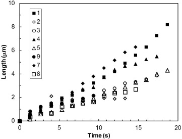
Fig. 3: Growth rate of dendrites (from fig. 1). Numbers refer to different droplets.
Download figure:
Standard imageDendrite growth vs. drop evaporation
Dendrites grow at the expense of evaporating droplets. The measurement of the area of evaporating droplets vs. time is depicted in fig. 4 for the droplets marked in fig. 1. For given local conditions, the decrease in area with time is approximately linear. Such a linear decrease is consistent with evaporation driven by molecular diffusion of water molecules through the droplet-vapor interface. In case of a sessile droplet, the diffusion flux diverges at the contact line, so that the evaporation rate is proportional to the perimeter of the droplet, dm/dt ≈ R (see, e.g., [19], and references therein). If there is no pinning of the contact line (constant contact angle), the equation of evolution of the droplet radius is dR3/dt ≈ R, leading to the time evolution: R2(t) ≈ R20 − αt, where α is a constant evaporation rate. We measure α ≈ 1.8–6.25 μm2/s in the case of the droplets in fig. 3 (this order of magnitude is confirmed by other measurements, not shown here). Note, however, that when the local conditions around the droplet change suddenly, such as when a neighboring liquid droplet is driven to a frozen state, the evolution remains linear but the value of α increases as a result of enhanced diffusion. The possibility of ice propagation is a competition between growth of dendrites with velocity V and evaporation of liquid droplets at rate α. Let us consider two identical droplets of initial radius R0, separated by the initial distance d0 between their interfaces. At time zero, one droplet freezes (the change of radius when freezing, less than 4%, is neglected) and emits a dendrite from its surface towards the neighboring droplet that has started to evaporate at the same time. The time tD at which this evaporating droplet vanishes is tD = R20/α. The dendrite makes contact with the center of the evaporating droplet, at time tC = (d0 + R0)/V . The condition for contact to occur before complete evaporation is tC < tD, leading to the following condition on the droplet initial radius:  . Assuming for simplicity that the drops lie on a squared lattice, the surface coverage is then given by
  and we obtain the condition on the initial drop radius,
  . Using the numerical values of our experiments, we find that the minimum radius is in the order of 23 μm, in accordance with the observations.
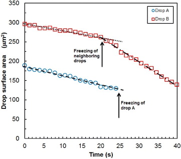
Fig. 4: (Colour on-line) Evolution of the surface area of evaporating droplets. (Measurements are made on the two drops marked A and B in fig. 1.) The values of the evaporation rate α (see text) depend on the environment of the evaporating droplet (dotted line: α = 1.8, dashed line α = 2.3; dash-dotted line: α = 6.25).
Download figure:
Standard imageDiscussion and summary
It must be stressed that the percolation process discovered here is essentially different from the growth of one single crystal at the expense of all available surrounding liquid droplets (see [13]). For this particular growth to occur, the nucleation must happen far from the breath figure, as illustrated in fig. 5, where an ice crystal has nucleated at the edge of our substrate at an initial distance d0 ≈ 80 μm from the supercooled droplets. In agreement with the above calculation, this value of d0 is too large to allow contact to be made with the droplets. The evaporating droplets vanish one after another, leaving a depleted zone around the crystal. Moreover, the velocity of this kind of ice propagation is equal to the velocity of crystal growth, whereas in the percolation process the propagation velocity is larger than the velocity of dendrite growth as a result of the nearly instantaneous freezing of drops when hit (the gain is ≈2R0/d0, which can increase the velocity by a factor of 2.5). In some applications, it could be interesting to modify the propagation speed of the freezing front by favoring one mechanism or another. The percolation process needs a small interdroplet distance to occur. The latter diminishes for more hydrophilic substrates (smaller water contact angle) [11]. However, a systematic study is planned to determine the limits of the percolation process to occur.
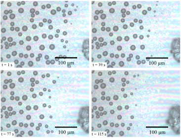
Fig. 5: (Colour on-line) Growth of an ice crystal (faceted edges at the right of the pictures) at the expense of neighboring droplets, for the case of large ice-to-droplet distance.
Download figure:
Standard imageThe important and main discovery of this work is that frost formation on a smooth hydrophobic surface occurs through supercooled water droplets that can percolate into a network of frozen droplets connected by ice dendrites. This is in striking contrast to earlier reports. In addition to evidencing a still ignored frost formation mode, this in-plane ice propagation process will be useful for modeling more complex 3D phase transformations such as those occurring in atmospheric supercooled clouds. As drop condensation can be controlled by coatings with different wetting properties, this percolation process can lead to a new means to control and design in-plane solidification of other materials, even at the nanoscale.
Acknowledgments
We are grateful to Dennis Lamb for valuable insights on cloud physics and S. Berkowicz for a critical reading of the manuscript. We gratefully acknowledge the comments and suggestions of M. Robert. This work was partly supported by the Spanish Government (MEC grant no. FIS2011-24642). JGC acknowledges financial support from the "Asociación de Amigos de la Universidad de Navarra".