
Abstract
Friction stir welding was used to produce butt joints on 6 mm thick plates of UNS S32101 lean duplex stainless steel, S32205 duplex stainless steel, and S32750 and S32760 superduplex stainless steels. Fully consolidated joints were achieved, with full penetration, using heat input of 1.37-1.50 kJ/mm. Specimens submitted to tensile testing performed perpendicular to the welding direction showed failure on the base metal, reflecting better mechanical performance of the welded joints. Furthermore, tensile testing along the joints revealed higher yield and tensile strengths in all cases, as well as increased elongation. Microstructural evaluation showed that there was pronounced grain refinement in the welded joints of all the materials studied, achieving grain sizes as small as 1 µm. The differences in the ferrite and austenite grain sizes in the stir zone, such as the degree of grain refinement, could be explained by the combination of dynamic recrystallization of austenite during the welding process and the recrystallization and growth of the ferrite grains, promoted firstly by the severe deformation and secondly by the high temperature inherent to the FSW process. Superduplex stainless steel FSW joints were more able to maintain a balanced microstructure, compared to conventional and lean duplex stainless steels, due to greater homogeneity of recrystallization in the welded joint.
Keywords:
Welding parameters; Friction stir welding; Duplex stainless steel
1 Introduction
Lean (LDSS), conventional (DSS) and superduplex (SDSS) stainless steel grades have often been adopted in offshore structures in preference to carbon or other stainless steels. The chemical composition of these materials provides them with a high level of resistance to localized corrosion (especially pitting) in salt water environments, as well as good mechanical strength and ductility11 Lippold JC, Kotechi DJ: Welding Metallurgy and Weldability of Stainless Steels, John Wiley & Sons Inc, Ohio, 2005.. DSS and SDSS have replaced austenitic stainless steel (ASS) in many applications where stress corrosion cracking and pitting corrosion are concerns, although ASS continues to be studied, due to its good formability22 Padilha AF, Rios PR: Decomposition of austenite in austenitic stainless steels. ISIJ International. 2002; 42: 325-337.,33 Santos TFA, Andrade, MS. Internal Friction on AISI 304 Stainless Steels with Low Tensile Deformations at Temperatures between -50 and 20 ºC. Advances in Materials Science and Engineering. 2010. 2010: 1-8.. Other benefits are the ability of some duplex grades to be used at sub-zero temperatures, together with resistance to stress corrosion cracking44 McGuire MF. Duplex Stainless Steel: Stainless Steel for Design Engineers, pp. 91-108, ASM International, Ohio, 2008.
5 Davis JR. Corrosion of Weldments, pp. 99-109, ASM International, Ohio, 2006.-66 Charles J, Chemelle P. The history of duplex developments, nowadays DSS: Properties and duplex market future trends. Proceeding of the 8th Duplex Stainless Steels Conference, Beaune, France, 2011, pp. 002.. This is achieved due to the balanced ferritic-austenitic fine-grain microstructure and the high proportion of alloying elements77 Garzon CM, Ramirez AJ. Growth kinetics of deleterious austenite in the welding microstructure of a UNS S32304 duplex stainless steel. Acta Materialia. 2006; 54: 3321-3331..
The UNS S32205 standard DSS was developed to compete with austenitic grade AISI 304L in terms of corrosion resistance, but with better mechanical performance. Continuous modifications have been made to improve corrosion resistance, formability, and weldability, such as the addition of nitrogen to enhance pitting corrosion resistance and weldability88 Olsson J, Snis M. Duplex - A new generation of stainless steels for desalination plants. Desalination. 2007: 205: 104–113.,99 Alvarez-Armas I. Duplex Stainless Steels: Brief History and Some Recent Alloys. Recent Patents on Mechanical Engineering. 2008; 1 (1): 51-57.. It has been reported that this steel still accounts for over 70% of duplex grade deliveries1010 Gagnepain J.-C. Duplex stainless steels: success story and growth perspectives. Stainless Steel World. 2008; 12: 32-36.. SDSS grades were developed for more aggressive environments, competing with superaustenitic stainless steels and nickel alloys. The high corrosion resistance of these alloys is due to high molybdenum (Mo) and nitrogen contents. The addition of Mo improves the localized corrosion resistance of DSS. However, it is known that Mo favors sigma phase precipitation1111 Sorensen CD, Nelson TW. Sigma Phase Formation in Friction Stirring of Iron-Nickel-Chromium Alloys. Proceedings of the 7th Conference on Trends in Welding Research, Georgia, USA, 2005, pp. 441-446.
12 Kim SB, Paik KW, Kim YG. Effect of Mo substitution by W on high temperature embrittlement characteristics in duplex stainless steels. Materials Science and Engineering A. 1998; 247: 67-74.
13 Lopez N, Cid M, Puiggali M. Influence of sigma-phase on mechanical properties and corrosion resistance of duplex stainless steels. Corrosion Science. 1999; 41: 1615-1631.
14 Kim JS, Kwon HS. Effects of Tungsten on Corrosion and Kinetics of Sigma Phase Formation of 25% Chromium Duplex Stainless Steels. Corrosion. 1999; 55 (5): 512-521.-1515 Park CJ, Ahn MK, Kwon HS. Influences of Mo substitution by W on the precipitation kinetics of deleterious phases and the associated localized corrosion and embrittlement in 29% Cr ferritic stainless steels. Materials Science and Engineering A. 2006; 418 (1): 211-217., which impairs the toughness and corrosion resistance of the material. Lean duplex stainless steel (LDSS) grades have lower nickel and molybdenum contents, which are balanced by increases in manganese and nitrogen. Their development is intended to lower the dependency on alloying elements, especially nickel and molybdenum, whose prices can fluctuate widely. LDSS has been used to replace the 304 and 316 steel grades in applications such as the construction of pressure vessels, bridges, and storage tanks1616 Westin EW, Olsson COA, Hertzman S. Weld oxide formation on lean duplex stainless steel. Corrosion Science. 2008; 50: 2620-2634.
17 Bhattacharya A, Singh PM. Role of microstructure on the corrosion susceptibility of UNS S32101 duplex stainless steel. Corrosion. 2008; 64: 532-540.-1818 Westin EW. Microstructure and properties of welds in the lean duplex stainless steel LDX 2101. [thesis]. Stockholm: Royal Institute of Technology; 2010..
During fusion welding, the thermal inputs and associated solidification destroy the favorable duplex microstructure of these stainless steels. In addition, precipitation of detrimental phases and coarsening of ferrite grains can take place. Friction stir welding (FSW) is a solid-state joining process that offers a number of advantages over conventional fusion welding techniques for joining DSS. For example, it enables elimination of several problems associated with fusion and solidification, such as high distortion, solidification cracking, and elevated porosity1919 Thomas WM, Nicholas ED, Needham JC, Murch MG, P. Temple-Smith and C.J. Dawes1995Friction Stir Butt WeldingUSPatent no. 5,460,317
20 Thomas WM, Nicholas ED. Friction stir welding for the transportation industries. Materials & Design. 1997; 18: 269-273.
21 Mishra RS, Mahoney MW. Friction Stir Welding and Processing, pp. 360, Ohio, ASM International, 2007.
22 Sato YS, Nelson TW, Sterling CS, Steel RJ, Pettersson CO. Microstructure and mechanical properties of friction stir welded SAF 2507 super duplex stainless steel. Materials Science and Engineering A. 2005; 395: 376-384.-2323 Defalco J. Friction Stir Welding vs. Fusion Welding. Welding Journal. 2006; 85 (3): 42-44.. It has been widely reported that several zones can be formed during FSW2424 Mishra RS, Ma ZY. Friction stir welding and processing. Materials Science and Engineering R. 2005; 50 (1): 1-78.
25 Nandan R, DebRoy T, Bhadeshia HKDH. Recent Advances in Friction Stir Welding – Process, Weldment Structure and Properties. Progress in Materials Science. 2008; 53: 980-1023.
26 Sivashanmugam M, Ravikumar S, Kumar T, Rao VS, Muruganandam D. A review of friction stir welding for aluminium alloys. IEEE. 2010; 216-221.-2727 Fonda RW, Bingert JF, Colligan KJ. Microstructural Development in Friction Stir Welding. Chemical/biochemical Research, 2005, pp. 120-122.. These are the stir zone (SZ), the thermo-mechanically affected zone (TMAZ), the heat-affected zone (HAZ), and the base metal (BM). Due to the material flow asymmetry inherent in FSW, the advancing (AS) and retreating (RS) sides undergo different thermo-mechanical histories. Figure 1 shows a schematic drawing of FSW with all the zones mentioned above. DSS2828 Santos TFA, Marinho RR, Paes MTP, Ramirez AJ. Microstructure evaluation of UNS S32205 duplex stainless steel friction stir welds. Revista Escola de Minas. 2013; 66 (2): 187-191. and SDSS2929 Santos TFA, Torres EA, Hermenegildo TFC, Ramirez AJ. Desenvolvimento de sistema de apoio com depósito cerâmico para soldagem e processamento por atrito com pinonão consumível. Soldagem & Inspeção. 2014; 19 (2): 104-113. do not show HAZs on both sides (AS and RS) of the welded joint. The formation of different regions and the presence of several metallographic phases cause variations in the mechanical and microstructural properties of the metal, which makes it necessary to determine whether such features are improved or worsened. Due to concern about the effects of microstructural changes, criteria have been developed for the identification of FSW joints whose characteristics are unsuitable for industrial application and should be discarded.

The aim of this work is to identify appropriate welding conditions for obtaining consolidated full penetration welding joints, considering the microstructural characteristics and mechanical performance of UNS S32101 LDSS, UNS S32205 DSS, and UNS S32750 and S32760 SDSS.
2 Experimental procedure
The chemical compositions (Table 1) and the mechanical properties of the base materials were provided by the steel producers: Outokumpu (UNS S32101 and S32750); Weir Materials (UNS S32760); and Aperam (UNS S32205). Chromium/nickel equivalent ratios were calculated using WRC-1992 diagrams, according to equations (1) and (2):
Butt joints were made using a dedicated Transformation Technologies, Inc. (TTI) FSW machine, which enables position and force control during welding. Plates (500 mm × 180 mm × 6.0 mm) were friction stir welded using an untilted composite tool consisting of polycrystalline cubic boron nitride in a metallic matrix of 40 vol.% W-Re (PCBN-40% W-Re), with 25.0 and 8.0 mm shoulder and pin diameters, respectively, 6.0 mm pin length, and axial load (in the welding direction) of 15 kN.
The FSW processes were performed at the Brazilian Nanotechnology National Laboratory (LNNano)/CNPEM, using a specially developed backing plate to support the axial forces generated during welding, ensuring the consistent production of full penetration joints. This backing plate has been described previously2929 Santos TFA, Torres EA, Hermenegildo TFC, Ramirez AJ. Desenvolvimento de sistema de apoio com depósito cerâmico para soldagem e processamento por atrito com pinonão consumível. Soldagem & Inspeção. 2014; 19 (2): 104-113..
The welding process was developed in two stages: preliminary and final joining. Preliminary welding parameters were chosen based on the work of Steel and Sterling 3030 Steel RJ, Sterling CJ. Friction Stir Welding of 2205 Duplex Stainless and 3Cr12 Steels. Proceedings of the 14th International Offshore and Polar Engineering Conference, Toulon, France, p. 67-73, 2004., using S32205 DSS friction stir welds with thickness of 5 mm. The welded joints were obtained using tool position control, with axial force ranging from 18 to 40 kN. Metallographic preparation and dry penetrant inspection of these joints were carried out, together with bending tests, in order to assess the presence of defects and obtain insights into the welded joints. The welding parameters that produced sound and full penetration joints were replicated for the final joints. Additionally, selection of the final parameters was based on the behavior of the tool during the welding process, as well as the surface appearance of the welded joints. During FSW, depending on the conditions employed, the tool may show cracks for low heat inputs and abrasion for high heat inputs. Here, it was found that above 500 rpm, the tool showed substantial abrasion, while below 100 rpm, the lateral forces were higher than 15 kN and the likelihood of breaking the tool increased drastically. Two sets of parameters were selected for performing the final joints: one to produce low heat input, and another to evaluate high heat input. Before obtaining the final condition, the heat input was changed by modifying the rotation and welding speeds, as well as the axial force, in order to keep the forces in the welding direction at or below 10 kN. This ensured the safety of the tool and extended its life to the entire duration of the stage of selection of the welding parameters. The preliminary and final welding parameters are shown in Table 2. An argon atmosphere was used to avoid oxide formation on the tool during the welding procedure.
The heat inputs of the final joints were calculated according to the equation (3) 3131 Wei LY, Nelson TW. Correlation of Microstructures and Process Variables in FSW HSLA-65 Steel. Welding Journal. 2011; 90: 95-s-101-s., where HI is the heat input (kJ/mm), T is the spindle torque recorded by the FSW machine (N.m), ω is the spindle speed (rpm), and ν is the welding speed (mm/min):
In the preliminary and final joints, the root of the joint was submitted to liquid penetrant testing to evaluate complete joint penetration. Dye penetration inspections were performed using a commercial penetrant liquid, in accordance with the manufacturer's instructions and the ASTM standard3232 ASTM E1417/E1417M-13, Standard Practice for Liquid Penetrant Testing, West Conshohocken, 2013., employing the following steps: cleaning, application of red dye penetrant, removal of excess penetrant, application of developer, examination, and post-cleaning. Transverse and longitudinal tensile tests and bending tests, employing rectangular specimens, were performed on the welded joints according to ASTM A370/E8, AWS B4.0.923333 AWS B4.0-92, Standard Methods for Mechanical Testing of Welds, Miami, 1992., and AWS B4.0.92, respectively.
The volume fractions of ferrite were determined by digital image analysis using ImageJ software. Ferrite grain size was measured by manual intercept counting, employing a superimposed circle of known perimeter, in accordance with ASTM E-1123434 ASTM E112-10, Standard Test Methods for Determining Average Grain Size, West Conshohocken, 2010.. Statistical treatment of the grain size and volume fraction data considered a confidence interval of 95%. An optical microscope and JSM 5900LV and Supra-55VP scanning electron microscopes were used for the metallographic analyses.
3 Results and Discussion
3.1 Joining process and obtaining consolidated full penetration welded joints
Two different grades of DSS and SDSS were tested using different FSW parameters (from this point onwards, LDSS will also be referred to as DSS). Welding parameters were evaluated in two steps: Preliminary and final tests, as described in the two following paragraphs.
Preliminary FSW tests were performed in position control mode to determine the best tool penetration to provide sound welds, a satisfactory surface finish, and reasonable axial and transverse forces. The initial tests were performed on grade S32760. The range of initial parameters was reduced to a set of two: parameters that provided a low or high heat input (HI) (Table 2). Equation 3 was used to calculate the HI. Other empirical relationships between the welding variables (inputs) and the instrumental outputs were used to develop the expression proposed here for the FSW heat input. Firstly, the pseudo heat index (PHI) and the advance per revolution (APR) index were used. However, according to studies performed by Wei and Nelson3131 Wei LY, Nelson TW. Correlation of Microstructures and Process Variables in FSW HSLA-65 Steel. Welding Journal. 2011; 90: 95-s-101-s., the heat input (HI) approach provides better correlation between post-weld microstructures and process variables in HSLA-65 steel systems.
The final welds were performed using downward force control mode, as indicated in Table 2. Figure 2a shows the FSW process being performed, with achievement of a good DSS surface finish (Figure 2b). Excellent surface quality was obtained for the weld face (Figure 2c) and the weld root (Figure 2d), considering that no cleaning was performed after welding. The average roughness values (Table 3) corroborated the good surface aspects.
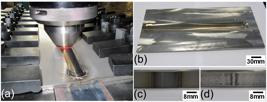
(a) Friction stir welding process, (b) a welded plate showing excellent surface finish, (c) weld face, and (d) weld root.
A cross section of FS welded UNS 32760 is shown in Figure 3, together with the different microstructural zones identified. Voids were observed on the advancing side of the joint when welding was performed at 450 rpm and 60 mm/min, which was related to the low flow of plasticized metal. According to Mishra and Mahoney2121 Mishra RS, Mahoney MW. Friction Stir Welding and Processing, pp. 360, Ohio, ASM International, 2007. and Kim et al.3535 Kim YG, Fujii H, Tsumura T, Komazaki TT, Nakata K. Three defect types in friction stir welding of aluminum die casting alloy. Materials Science and Engineering A. 2006; 415 (1): 250-254., this could be attributed to insufficient heat input (0.89 kJ/mm). Rajakumar et al.3636 Rajakumar S, Muralidharan C, Balasubramanian V. Influence of friction stir welding process and tool parameters on strength properties of AA7075-T6 aluminium alloy joints. Materials & Design. 2011; 32 (2): 535-549. showed that the presence of wormholes on the advancing side of the welded joint can be caused by a lack of flow due to low heat input during the process. The lower axial force, combined with higher spindle speed and lower transverse speed, resulted in lower torque on the welded joint, in agreement with lower heat input (Table 2). According to Equation 3, the heat input should increase with higher spindle speed and lower transverse speed3737 Fujii H, Cui L, Tsuji N, Maeda M, Nakata K, Nogi K. Friction stir welding of carbon steels. Materials Science and Engineering A. 2006; 429 (1): 50-57.,3838 Cui L, Fujii H, Tsuji N, Nogi K. Friction stir welding of a high carbon steel. Scripta Materialia. 2007; 56 (7): 637-640.. However, it is necessary to consider the influence of torque, which is governed by the flow characteristics of the material and the spindle speed. Greater heat input increases the fluidity of the metal, allowing it to completely fill the joint, hence obtaining a sound welded joint. In this work, consolidated joints were observed at 200 rpm and 100 mm/min (1.37-1.50 kJ/mm) (Table 2).

Optical microscopy cross section of a friction stir welded UNS S32760 SDSS joint: (a) macrograph of welded joint, (b) SZ/TMAZ-AS interface showing a fill defect, (c) BM, (d) SZ, and (e) TMAZ on advancing side.
In addition to rotation and welding speeds, used as heat input control parameters, Kumar and Kailas3939 Kumar K, Kailas SV. The role of friction stir welding tool on material flow and weld formation. Materials Science and Engineering A. 2008; 485 (1): 367-374. showed the influence of the axial force in the contact area between the tool and the workpiece, and consequently of the heat generated during welding. In the current work, the increase of HI, at reduced spindle speed and increased welding speed, was due to the effect of the axial load, which changed from 22 to 37 kN (Table 2), increasing the contact area between tool and joint. Hence, the insufficient heat input observed using the former parameters could be attributed to lower axial force, because higher spindle speeds are expected to increase the HI.
Macrographs of the welded joints obtained using HI of 1.38 kJ/mm are shown in Figure 4. The cross sections showed consolidated joints with full penetration. Figure 5a shows the faces of FSW joints for the S32101, S32750, and S32760 samples, which presented excellent surface quality. Liquid penetrant testing of these plates confirmed the full penetration of the joints (Figure 5b). The purpose of dye penetration inspection was to reject samples that showed discontinuities such as opened weld roots, cracks, and porosity, prior to the bending test. Nevertheless, it is important to point out that certain FSW defects, such as joint line remnants, cannot be observed by this method.


Welded joints of UNS S32101, S32750, and S32760 DSS: (a) face, (b) root submitted to liquid penetrant test.
The evolution of downward force (Fz), force in the welding direction (Fx), and tool temperature was followed during welding (Figure 6). The tool temperature was measured by a thermocouple positioned in the tool shoulder. This thermocouple did not provide the exact tool temperature at the interface with the processing material within the stir zone. However, due to the high thermal conductivity of PCBN, it provided comparative values for different welding parameters and final microstructures4040 Steel RJ, Pettersson CO, Parcker SM, Sorensen CD, Sato YS, Nelson TW. Friction Stir Welding of SAF 2507 (UNS S32750) Super Duplex Stainless Steel. Stainless Steel World. 2004; 16: 27-31.,4141 Santos TFA, Hermenegildo TFC, Afonso CRM, Marinho RR, Paes MTP, Ramirez AJ. Fracture toughness of ISO 3183 X80M (API 5L X80) steel friction stir welds. Engineering Fracture Mechanics. 2010; 77: 2937-2945..The thermocouples in the tool reached temperatures that were not higher than 860 ºC. The force in the welding direction did not exceed 10 kN at any time during welding (Table 2), which reduced the likelihood of breaking the tool (which had a maximum load capacity of approximately 15 kN, according to the manufacturer).
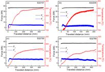
Evolution of downward force (Fz), force in the welding direction (Fx), and tool temperature: (a) S32101, (b) S32205, (c) S32750, and (d) S32760.
Data extracted from Figure 6 are summarized in Table 4. The FSW machine was able to maintain the same downward force for all the systems studied. Due to the higher recrystallization potential of SDSS (S32750 and S32760), compared to DSS (S32101 and S32205), the SDSS samples seemed to be more deformable during FSW. This is a direct consequence of DSS being more prone to strain hardening at high temperatures, compared to SDSS, which undergoes dynamic recrystallization (DRX) more easily. During welding, this is reflected in higher torque when processing DSS. Since the temperature in the welded region is strongly related to adiabatic heating due to deformation, the DSS plates showed higher temperatures, compared to the SDSS samples. Since higher temperatures cause a higher degree of plasticization in the material, the forces in the welding direction were lower for DSS than for SDSS.
3.2 Microstructural characterization
The base metal (BM) microstructures of all the samples in three directions are shown in Figure 7. These steels are frequently submitted to cross rolling in the first steps of rolling in order to minimize anisotropy in the finished product. During cross rolling, the plate is repeatedly turned by 90° after each deformation step, giving the plates a more uniform microstructure and homogeneous properties in both longitudinal and transverse directions.

Base metal microstructure. Normal, transverse, and rolling directions are specified for all samples.
Although both directions can be called rolling directions, this work adopted the longitudinal direction or last pass of rolling as the rolling direction. The BM microstructure consisted of austenite islands in a ferrite matrix, with ferrite/austenite ratios of around 50:50 for all samples (Table 5). The grain size measured in the normal direction (ND) was between 11 and 13 µm for ferrite and between 8.5 and 11 µm for austenite (Table 6). The microstructural characteristics along the ND of materials submitted to cross rolling were quite different from the other directions (transverse and rolling directions). For improved stereological analysis, the thicknesses of the lamellae were measured in the transverse and rolling directions. No significant differences were noticed between these directions. The average measured thicknesses of the lamellae therefore applied to both directions, and were between 4.5 and 6.5 µm in the base metals.
Ferritic and austenitic grain sizes (µm) for different regions of all the materials studied in this work.
All the final welded joints showed a 17 mm bead width, and the use of suitable parameters resulted in consolidated joints with full penetration. To achieve satisfactory final joints, tool penetration was an important parameter that affected the heat input, at constant spindle and welding speeds. The cross sections of the friction stir welded joints were similar for all the samples; examination of the microstructure is illustrated in Figure 8 for the UNS S32750 FSW joint, indicating the different microstructural zones. The combined thermal and mechanical effects in the TMAZ produced a characteristic microstructure, with the material flow lines visible in Figure 8a. The stir zone (SZ) showed equiaxed grains with severely reduced sizes, which changed from 11 and 9 μm in the base metal, to 3.1 and 1.3 μm, for ferrite and austenite, respectively, indicating that dynamic recrystallization occurred during FSW (Figure 8b). The stir zone on the advancing side (SZ-AS) showed clear size reductions for both phases, up to 1.7 and 1.1 μm (Figure 8c), indicating the occurrence of a more severe strain process. The interface between the SZ and the TMAZ, on the advancing side (Figure 8d), showed the flow of both phases, but only the ferrite grains seemed to show signs of a recovery mechanism, resulting from the formation of subgrains, which is the early stage of dynamic recrystallization. Due to the higher stacking fault energy (SFE) of ferrite, it tends to undergo dynamic recovery (DRV), while austenite, with lower SFE, is more prone to dynamic recrystallization (DRX). In both phases, severe deformation promotes the activation of different recrystallization mechanisms: discontinuous dynamic recrystallization (DDRX) and continuous dynamic recrystallization (CDRX)4242 Doherty RD, Hughes DA, Humphreys FJ, Jonas JJ, Juul Jensen D, Kassner ME, King WE, Mcnelley TR, Mcqueen HJ, Rollett AD. Current issues in recrystallization: A review. Materials Science and Engineering A. 1997: 238: 219-274.,4343 Humphreys FJ, Hatherly M. Recrystallization and Related Annealing Phenomena. Oxford, Elsevier, 2004, pp. 628.. DDRX, promoted by the austenite, follows classical DRX, with two stages of nucleation and the growth of a sub-grain structure by the continuous accumulation of dislocations. CDRX, produced in ferrite, is generated by the progressive rotation of a cell arranged in the strain structure and the continuous absorption of dislocation by the cell walls. Finally, the TMAZ-AS (Figure 8e) presented few indications of strain, as well as evidence of the activation of a recovery mechanism.

Optical microscopy cross sections of UNS S32750 SDSS FSW joint: (a) macrograph of welded joint, (b) SZ, (c) SZ-AS, (d) SZ/TMAZ-AS interface, and (e) details of TMAZ-AS.
Figure 9 shows the SZ-RS and SZ-AS, illustrating the differences in grain size of the ferrite and austenite. In the microstructure of the SZ-RS (Figure 9a), the grains of austenite were finer than the ferrite grains (Table 6). This size difference was explained by Sato et al.2222 Sato YS, Nelson TW, Sterling CS, Steel RJ, Pettersson CO. Microstructure and mechanical properties of friction stir welded SAF 2507 super duplex stainless steel. Materials Science and Engineering A. 2005; 395: 376-384. as due to the constant dynamic recrystallization of austenite during the strain, together with the recrystallization and growth of the ferrite grains. On the other hand, the microstructure of the SZ-AS (Figure 9b) presented equiaxed fine grains, indicating that there had been dynamic recrystallization of both phases, as described previously4444 Momemi A, Dehghani K, Zhang XK. Mechanical and microestrutural analysis of 2205 duplex stainless steel under hot working condition. journal of Materials Science. 2011; 47: 2966-2974.
45 Reis GS, Jorge AM, Balancin O. Influence of the microstructure of duplex stainless steel on their failure characteristics during hot deformation. Materials Research. 2000; 3 (2): 31-35.-4646 Reick W, Pohl M, Padilha AF. Recrystallization-transformation combined reactions during annealing of a cold rolled ferritic-austenitic duplex stainless steel. ISIJ International. 1998; 38 (6): 567-571..

Scanning electron microscopy (SEM) images of friction stir welded UNS S32750 SDSS: (a) SZ-RS and (b) SZ-AS.
Figure 10 shows the stir zones of the steels studied in this work: UNS S32101 (a), S32205 (b), S32750 (c), and S32760 (d). All the samples exhibited the same microstructural characteristics, with approximately the same austenitic and ferritic grain sizes, and subtle differences of ferrite volume fraction. The austenitic grain size in the SZ of all samples was between 1.0 and 1.3 µm (Table 6). The ferrite volume fraction was higher for DSS, compared to SDSS, which was probably related to the fact that DSS has a higher chromium/nickel equivalent ratio, and is therefore more liable to form ferrite at elevated temperatures.

Scanning electron microscopy (SEM) images of friction stir welded joints: SZ of UNS (a) SS32101, (b) S32205, (c) S32750, and (d) S32760.
The ferrite volume fraction in the TMAZ-RS was between 50 and 60% for all the FSW joints, with the exception of S32205. The characterization of the TMAZ-RS was complicated by the fact that there were no clear boundaries to define where it started and finished. Instead, there was a very subtle change from the SZ-RS to the BM, where the material received sufficient energy in the form of both heat and deformation to permit microstructural reformation. Large differences from the BM volume fraction were not expected and were not observed. The TMAZ-RS of S32205 was very similar to the SZ-RS (Table 5, Figure 11), where the main feature was an increase in the volume fraction of ferrite, promoted by the high temperature reached during the process. On the other hand, in the case of the TMAZ-AS, there was a clearly discernible interface with the SZ-AS, and the ferrite volume fraction was between 50 and 60%.

For all the DSS samples, the SZ-RS, SZ-center, and SZ-root regions showed microstructural characteristics that differed from those of the SZ-AS. A higher ferrite volume fraction was evident for S32101 DSS, followed by S32205 DSS and the two SDSSs. This behavior could be due to the thermal dispersion (peak temperature) in each of these regions, where the higher volume fraction of ferrite in S32101 could be explained by the higher chromium/nickel ratio, compared to S32205 and the SDSSs. In research employing an aluminum alloy (AA7075), Su and co-workers4747 Su JQ, Nelson TW, Mishra R, Mahoney M. Microstructural investigation of friction stir welded 7050-T651 aluminium. Acta Materialia. 2003; 51 (3): 713-729.,4848 Su JQ, Nelson TW, Sterling CJ. Mater. Microstructure evolution during FSW/FSP of high strength aluminum alloys. Materials Science and Engineering A. 2005; 405 (1): 277-286. found that differences in dislocation density and grain size in all the regions of the SZ were due to differences in temperature, together with strains caused by the tool during the welding, which affected recrystallization and the grain growth process. Despite the clear differences among materials, it is expected that the effect of the tool on the temperature and the degree of strain should be the same for any joint made by FSW. Additionally, no deleterious phase precipitation in any of the materials was observed by optical microscopy and SEM. Previous studies of friction stir welding with SDSS UNS S327502222 Sato YS, Nelson TW, Sterling CS, Steel RJ, Pettersson CO. Microstructure and mechanical properties of friction stir welded SAF 2507 super duplex stainless steel. Materials Science and Engineering A. 2005; 395: 376-384.,4040 Steel RJ, Pettersson CO, Parcker SM, Sorensen CD, Sato YS, Nelson TW. Friction Stir Welding of SAF 2507 (UNS S32750) Super Duplex Stainless Steel. Stainless Steel World. 2004; 16: 27-31. and DSS UNS S322052828 Santos TFA, Marinho RR, Paes MTP, Ramirez AJ. Microstructure evaluation of UNS S32205 duplex stainless steel friction stir welds. Revista Escola de Minas. 2013; 66 (2): 187-191.,4040 Steel RJ, Pettersson CO, Parcker SM, Sorensen CD, Sato YS, Nelson TW. Friction Stir Welding of SAF 2507 (UNS S32750) Super Duplex Stainless Steel. Stainless Steel World. 2004; 16: 27-31.,4949 Saied T, Abdollah-zadeh A, Assadi H, Malek Ghaini H. Effect of friction stir welding speed on the microstructure and mechanical properties of a duplex stainless steel. Mater.Materials Science and Engineering A. 2008; 496: 262-268. also found no detrimental secondary phase precipitation. In other work5050 Santos TFA, Idagawa HS, Ramirez AJ. Thermal history in UNS S32205 duplex stainless steel friction stir welds. Science and Technology of Welding and Joining. 2014; 19: 150-156., it was shown that during the thermal cycle of FSW joints, the temperature peak was lower, and the time spent at high temperature was shorter, compared to the CGHAZ (coarse grain heat affected zone) of UNS S32205 GTA welds.
Figure 12 summarizes the grain size distributions in the stir zone, the TMAZ, and the base metal. The SZ showed the smallest grain sizes of all regions in all the FSW joints, due to the recrystallization that occurred during the process. The TMAZ-RS and TMAZ-AS showed smaller grain sizes and roughly the same lamella thickness, compared to the BM. No significant changes related to grain size distribution were observed in the TMAZ.

Grain sizes for (a) S32101, (b) S32205, (c) S32750, and (d) S32760. BM is the base metal grain size and BM* is the thickness of the BM lamellae.
The austenitic grain size in the SZ was below 2 µm, indicating a high degree of grain refinement. The ferritic grain size distribution in the SZ is shown in greater detail in Figure 12. The ferritic grain size diminished from the SZ-RS to the SZ-AS, with the SZ-AS showing more severe ferrite and austenite grain refinement in all the welded joints as shown in Figure 13. The greater deformation at elevated temperature in the SZ-AS resulted in higher recrystallization potential and achievement of a refined and fully recrystallized microstructure. Although the SZ-RS and SZ-root regions showed higher ferrite volume fractions and larger grain sizes, it is important to highlight that the grain size and the lamella thickness were smaller than for BM. Additionally, the ferrite volume fraction was around 70% for DSS and 50% for SDSS, which indicates that FSW is a very promising welding technology for use with SDSS.

3.3 Mechanical properties
Figure 14 shows the results of transverse tensile testing of the UNS S32101 (a), S32750 (b), and S32760 (c) joints. All the welded joints failed in the base metal. UNS S32205 was not tested due to the unavailability of samples of the size required according to the standard protocol. All the materials studied showed increases of yield strength (YS) and tensile strength (TS) in the presence of a joint, compared to the base metal. Nonetheless, it is important to highlight that the qualitative transverse tensile testing resulted in failures in the inhomogeneous samples (BM+welded joint).

Transverse tensile tests of UNS (a) S32101, (b) S32750, and (c) S32760. Longitudinal tensile tests (d) of UNS S32101, S32750, and S32760 FSW joints. (e)-(f) Different views of bent samples of S32101.
Samples submitted to longitudinal mechanical tests (Figure 14d) showed increases in YS and TS of the welded joint, compared to the base metal (Table 7)5151 Outokumpu, UNSS32101 and UNSS32750. 2009. Inspection certificate nº 1781436-EN and 1781438-EN,5252 Weir Materials, UNSS32760. 2003. Inspection certificate nº 15688/0B. Sato et al.2222 Sato YS, Nelson TW, Sterling CS, Steel RJ, Pettersson CO. Microstructure and mechanical properties of friction stir welded SAF 2507 super duplex stainless steel. Materials Science and Engineering A. 2005; 395: 376-384. observed the same yield and tensile strengths for S32750 FSW joints, compared to the base metal, using transverse tensile tests. However, they reported lower elongation values. All the samples analyzed here showed increases in ductility, along with increases in YS and TS, as expected due to the overall reduction in grain size. Bent root samples indicated the consolidation of joints, with full penetration. Bent root samples of UNS S32101 are shown in Figures 14e and 14f, and the same behavior was observed for the other materials studied in this work. Additionally, radiographic examination did not reveal any internal defects in the joints. On the other hand, the S32760 joint showed a significant decrease in ductility.
Some of the commonest problems in FSW are voids, joint line remnants, and incomplete penetration2121 Mishra RS, Mahoney MW. Friction Stir Welding and Processing, pp. 360, Ohio, ASM International, 2007. In particular, complete penetration is an important aspect that is difficult to achieve when materials are welded at high temperature. Some studies have been undertaken using FSW of DSS or SDSS2222 Sato YS, Nelson TW, Sterling CS, Steel RJ, Pettersson CO. Microstructure and mechanical properties of friction stir welded SAF 2507 super duplex stainless steel. Materials Science and Engineering A. 2005; 395: 376-384.,4949 Saied T, Abdollah-zadeh A, Assadi H, Malek Ghaini H. Effect of friction stir welding speed on the microstructure and mechanical properties of a duplex stainless steel. Mater.Materials Science and Engineering A. 2008; 496: 262-268., but few data are available concerning root penetration. In this study, consolidated welded joints with full penetration were produced by FSW. These joints presented significant increases in yield and tensile strength, as well as better ductility, with the exception of UNS S32760. In the case of UNS S32101, the FSW joints exhibited increases of 15% for YS and TS, and 23% for elongation. Moreover, S32750 showed increases of 36% for YS, 15% for TS, and an outstanding increase of 70% for elongation. The SDSS samples proved to be more capable of maintaining the proportion of ferrite, with a high degree of grain size refinement. The better results for SDSS could be attributed to a lower propensity to form ferrite, together with a uniform microstructure during FSW, which could be explained by the lower chromium/nickel ratio of the material.
Some authors have claimed that a ferrite content between 35 and 60% is sufficient to ensure optimal weld properties during fusion welding5353 Messer B, Oprea V, Wright A. Duplex stainless steel welding: best practices. Stainless Steel World. 2007; 53-63.,5454 Taban E, Kaluc E. Welding behaviour of duplex and superduplex stainless steels using laser and plasma arc welding processes. Welding in the World. 2011; 55: 47-58.. However, for practical applications, the acceptable ferrite content of the weld metal is in the range 30-70%. The high alloy content and the presence of a ferritic matrix renders DSS susceptible to embrittlement, and prolonged exposure to elevated temperatures results in the loss of mechanical and corrosion performance. High ferrite content was observed in the SZ and SZ-root regions of the UNS S32101 joint. Nevertheless, the mechanical properties of the joints were superior to those of the BM. Furthermore, deleterious phase precipitation was not observed in the DSS joints. Cooling rates measured during FSW of S322055050 Santos TFA, Idagawa HS, Ramirez AJ. Thermal history in UNS S32205 duplex stainless steel friction stir welds. Science and Technology of Welding and Joining. 2014; 19: 150-156. were higher than reported for GTAW of S32205 by Ramirez et al 5555 Ramirez AJ, Brandi, SD. Application of discrete distribution point heat source model to simulate multipass weld thermal cycles in medium thick plates. Science and Technology of Welding and Joining. 2004; 9: 72-82.. Furthermore, the time that the material remains at elevated temperatures is shorter in FSW, avoiding deleterious precipitation of phases such as sigma phase. Prevention of sigma phase formation from ferrite requires rapid cooling from 900 to 500 ºC1. It is known that the presence of deleterious phases in DSS and SDSS strongly compromises corrosion performance.
In fusion welding, the heat-affected zone (HAZ) is a critical region where loss of mechanical and corrosion-resistance performance can occur due to an unbalanced ratio between ferrite and austenite, with brittle detrimental phase precipitation. This is due to the high temperatures and cooling rates obtained during welding5656 Ramirez AJ, Lippold JC, Brandi SD. The Relationship between Chromium Nitride and Deleterious Austenite Precipitation in Duplex Stainless Steels. Metallurgical and Materials Transactions A. 2003; 34: 1575-1597.. No HAZ was observed during FSW of the DSS and SDSS samples, which could be attributed to the thermo-mechanical processing during welding. The characteristics of the TMAZ-RS and TMAZ-AS regions were intermediate between those of the SZ and the BM. The grain size in the TMAZ was roughly similar to the thickness of the BM lamellae, and smaller than the BM grain size. The ferritic volume fraction was between 50 and 60%, in a narrower range than reported for conventional fusion welding. For all the materials studied, the SZ showed substantial refinement of the grain sizes of ferrite (~3.0 µm) and austenite (~1.0 µm). The size of austenitic grains was around 1.0 µm in all regions of the SZ (RS, root, and AS), for all the materials (S32101, S32205, S32750, and S32760). The ferritic grain size distributions through the SZ showed similar patterns for the samples, with larger grains for the SZ-RS (~5 µm) and a decrease to approximately 1.0 µm for the SZ-AS. Although the SZ-RS and SZ-root regions showed ferritic volume fractions up to 70% for the DSS samples, the mechanical properties of S32101 indicated good performance. For the SDSS samples, the ferritic volume fractions were between 50 and 60%, associated with a strongly refined microstructure and corroborating the excellent mechanical properties of these materials.
The microstructural characteristics of the DSS (S32101 and S32205) and SDSS (S32750 and S32760) welded joints included strong grain refinement in the SZ-AS, due to the higher degree of deformation that occurred in this region. There was complete dynamic recrystallization of the structure in the SZ-AS, while other regions (SZ-RS, SZ, and SZ-root) showed structures consisting of reformed austenite in a ferrite matrix. Additionally, austenite exhibited more refined equiaxed grains in the SZ-AS, supporting the occurrence of dynamic recrystallization. In the case of ferrite, the severe strain5757 Reick W, Pohl M, Padilha AF. Recrystallization-Transformation combined reactions during annealing of a cold rolled ferritic-austenitic duplex stainless steel. ISIJ International. 1998; 38: 567-571. resulted in a shift from dynamic recovery to a continuous dynamic recrystallization reformulation mechanism, even though austenite presents higher strain hardening and a greater driving force for recrystallization, compared to ferrite. Ferrite presented a strong grain refinement similar to austenite in the SZ-AS. These refined microstructures resulted in better mechanical performance of the FSW joints. The SDSS materials exhibited greater increases of YS and TS, compared to S32101, which could be explained by a greater capacity of SDSS to maintain the balanced dual phase microstructure. In addition, the overall grain size reduction contributed to the better mechanical performance of the SDSS FSW joints. The stronger grain refinement and higher mechanical performance were reflected in the FSW output parameters: the forces in the welding direction (Fx) for the SDSSs (6.73 and 7.38 kN) were almost twice as large as for the DSSs. In the case of the SDSSs, the FSW joint of S32760 presented higher Fx (7.38 kN), compared to S32750 (6.73 kN), reflecting the decreased ductility of the S32760 welded joint. Both SDSSs are strongly modified with alloying elements, which makes them more prone to detrimental phase precipitation. Although precipitates were not found in the SEM analyses, it is likely that some precipitation could occur, especially in the case of the S32760 FSW joint, because of the large decrease in ductility. Corrosion performance and EBSD analyses are being carried out to investigate this possibility for S32760 welded joints. Although sigma phase was not detected in the microstructural characterization, the sodium hydroxide etch test (ASTM A 923), used to check for deleterious secondary phases (Test Method A), indicated an affected microstructure, while the ferrite chloride corrosion test (Test Method C) indicated a large weight loss5858 Santos TFA. Avaliação microestrutural e de desempenho de juntas soldadas de aços inoxidáveis duplex por atrito com pino não consumível. [Thesis]. Campinas: Universidade Estadual de Campinas; 2012..
Figure 15 shows the relationship between the chromium/nickel equivalent ratio and the tool temperature during FSW. The recrystallization potential is intimately related to the chemical composition of the alloys, as is the adiabatic heating. A lower chromium/nickel equivalent ratio results in a higher recrystallization potential. Hence, DSSs with higher chromium/nickel equivalent ratios are less prone to recrystallization and they consume less energy during microstructural restoration, which is reflected in a higher tool temperature during FSW. Other grades of DSS are expected to show similar features.
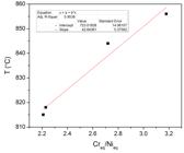
Relationship between the chromium/nickel equivalent ratio and the tool temperature during FSW.
4 Conclusions
Consolidated joints, with full penetration and absence of defects, were produced by friction stir welding. The joints provided increased yield and ultimate tensile strengths for UNS S32101, S32750, and S32760 steels, associated with strong grain refinement. The mechanical performance corroborated the improved mechanical properties for UNS S32101 and S32750.
Besides the transverse and spindle speeds, the axial force (or tool penetration) is an important parameter that needs to be considered in order to define the heat input, because it controls the contact area between the tool and the workpiece and influences the fluidity of the metal.
The behavior of the materials during FSW showed that the SDSSs, followed by UNS S32205 and S32101, were more capable of maintaining a balanced microstructure in the welded joint, which resulted in a better mechanical performance.
The grain refinement was similar for all the welded joints, indicating that FSW is not affected significantly by differences in the chemical composition of DSSs and SDSSs, which could be highly beneficial from a practical viewpoint.
The refinement of ferrite and austenite grains in the welded region was confirmed. The greatest reduction of grain size was observed in the stir zone, on the advancing side, and could be explained by the recrystallization of both phases (ferrite and austenite), promoted by the extreme deformation and high temperature. These conditions stimulated DDRX and CDRX, in the austenite and ferrite, respectively, where the recrystallization mechanisms were linked to the stacking fault energy of each phase.
The differences in the ferrite and austenite grain sizes in the SZ could be explained by the combination of constant dynamic recrystallization of austenite during the welding process and the recrystallization and growth of the ferrite grains, stimulated firstly by the severe deformation and secondly by the high temperature inherent to the FSW process.
Increased volume fractions of ferrite in the stir zones were associated with the peak temperatures in these regions. The maximum volume fraction of ferrite was obtained for S32101, due to its higher chromium/nickel ratio, followed by S32205 and the SDSSs.
Acknowledgments
The authors thank Petrobras and FINEP for financial support. Scholarships were provided by CNPq and FAPESP. The assistance provided by LNNano (CNPEM/MCTI) and OSU is gratefully acknowledged. The DSS and SDSS steel plates were kindly donated by Outokumpu, Weir Materials, and Aperam. TFAS also thanks UFPE and FACEPE.
References
-
1Lippold JC, Kotechi DJ: Welding Metallurgy and Weldability of Stainless Steels, John Wiley & Sons Inc, Ohio, 2005.
-
2Padilha AF, Rios PR: Decomposition of austenite in austenitic stainless steels. ISIJ International. 2002; 42: 325-337.
-
3Santos TFA, Andrade, MS. Internal Friction on AISI 304 Stainless Steels with Low Tensile Deformations at Temperatures between -50 and 20 ºC. Advances in Materials Science and Engineering. 2010. 2010: 1-8.
-
4McGuire MF. Duplex Stainless Steel: Stainless Steel for Design Engineers, pp. 91-108, ASM International, Ohio, 2008.
-
5Davis JR. Corrosion of Weldments, pp. 99-109, ASM International, Ohio, 2006.
-
6Charles J, Chemelle P. The history of duplex developments, nowadays DSS: Properties and duplex market future trends. Proceeding of the 8th Duplex Stainless Steels Conference, Beaune, France, 2011, pp. 002.
-
7Garzon CM, Ramirez AJ. Growth kinetics of deleterious austenite in the welding microstructure of a UNS S32304 duplex stainless steel. Acta Materialia. 2006; 54: 3321-3331.
-
8Olsson J, Snis M. Duplex - A new generation of stainless steels for desalination plants. Desalination. 2007: 205: 104–113.
-
9Alvarez-Armas I. Duplex Stainless Steels: Brief History and Some Recent Alloys. Recent Patents on Mechanical Engineering. 2008; 1 (1): 51-57.
-
10Gagnepain J.-C. Duplex stainless steels: success story and growth perspectives. Stainless Steel World. 2008; 12: 32-36.
-
11Sorensen CD, Nelson TW. Sigma Phase Formation in Friction Stirring of Iron-Nickel-Chromium Alloys. Proceedings of the 7th Conference on Trends in Welding Research, Georgia, USA, 2005, pp. 441-446.
-
12Kim SB, Paik KW, Kim YG. Effect of Mo substitution by W on high temperature embrittlement characteristics in duplex stainless steels. Materials Science and Engineering A. 1998; 247: 67-74.
-
13Lopez N, Cid M, Puiggali M. Influence of sigma-phase on mechanical properties and corrosion resistance of duplex stainless steels. Corrosion Science. 1999; 41: 1615-1631.
-
14Kim JS, Kwon HS. Effects of Tungsten on Corrosion and Kinetics of Sigma Phase Formation of 25% Chromium Duplex Stainless Steels. Corrosion. 1999; 55 (5): 512-521.
-
15Park CJ, Ahn MK, Kwon HS. Influences of Mo substitution by W on the precipitation kinetics of deleterious phases and the associated localized corrosion and embrittlement in 29% Cr ferritic stainless steels. Materials Science and Engineering A. 2006; 418 (1): 211-217.
-
16Westin EW, Olsson COA, Hertzman S. Weld oxide formation on lean duplex stainless steel. Corrosion Science. 2008; 50: 2620-2634.
-
17Bhattacharya A, Singh PM. Role of microstructure on the corrosion susceptibility of UNS S32101 duplex stainless steel. Corrosion. 2008; 64: 532-540.
-
18Westin EW. Microstructure and properties of welds in the lean duplex stainless steel LDX 2101. [thesis]. Stockholm: Royal Institute of Technology; 2010.
-
19Thomas WM, Nicholas ED, Needham JC, Murch MG, P. Temple-Smith and C.J. Dawes1995Friction Stir Butt WeldingUSPatent no. 5,460,317
-
20Thomas WM, Nicholas ED. Friction stir welding for the transportation industries. Materials & Design. 1997; 18: 269-273.
-
21Mishra RS, Mahoney MW. Friction Stir Welding and Processing, pp. 360, Ohio, ASM International, 2007.
-
22Sato YS, Nelson TW, Sterling CS, Steel RJ, Pettersson CO. Microstructure and mechanical properties of friction stir welded SAF 2507 super duplex stainless steel. Materials Science and Engineering A. 2005; 395: 376-384.
-
23Defalco J. Friction Stir Welding vs. Fusion Welding. Welding Journal. 2006; 85 (3): 42-44.
-
24Mishra RS, Ma ZY. Friction stir welding and processing. Materials Science and Engineering R. 2005; 50 (1): 1-78.
-
25Nandan R, DebRoy T, Bhadeshia HKDH. Recent Advances in Friction Stir Welding – Process, Weldment Structure and Properties. Progress in Materials Science. 2008; 53: 980-1023.
-
26Sivashanmugam M, Ravikumar S, Kumar T, Rao VS, Muruganandam D. A review of friction stir welding for aluminium alloys. IEEE. 2010; 216-221.
-
27Fonda RW, Bingert JF, Colligan KJ. Microstructural Development in Friction Stir Welding. Chemical/biochemical Research, 2005, pp. 120-122.
-
28Santos TFA, Marinho RR, Paes MTP, Ramirez AJ. Microstructure evaluation of UNS S32205 duplex stainless steel friction stir welds. Revista Escola de Minas. 2013; 66 (2): 187-191.
-
29Santos TFA, Torres EA, Hermenegildo TFC, Ramirez AJ. Desenvolvimento de sistema de apoio com depósito cerâmico para soldagem e processamento por atrito com pinonão consumível. Soldagem & Inspeção. 2014; 19 (2): 104-113.
-
30Steel RJ, Sterling CJ. Friction Stir Welding of 2205 Duplex Stainless and 3Cr12 Steels. Proceedings of the 14th International Offshore and Polar Engineering Conference, Toulon, France, p. 67-73, 2004.
-
31Wei LY, Nelson TW. Correlation of Microstructures and Process Variables in FSW HSLA-65 Steel. Welding Journal. 2011; 90: 95-s-101-s.
-
32ASTM E1417/E1417M-13, Standard Practice for Liquid Penetrant Testing, West Conshohocken, 2013.
-
33AWS B4.0-92, Standard Methods for Mechanical Testing of Welds, Miami, 1992.
-
34ASTM E112-10, Standard Test Methods for Determining Average Grain Size, West Conshohocken, 2010.
-
35Kim YG, Fujii H, Tsumura T, Komazaki TT, Nakata K. Three defect types in friction stir welding of aluminum die casting alloy. Materials Science and Engineering A. 2006; 415 (1): 250-254.
-
36Rajakumar S, Muralidharan C, Balasubramanian V. Influence of friction stir welding process and tool parameters on strength properties of AA7075-T6 aluminium alloy joints. Materials & Design. 2011; 32 (2): 535-549.
-
37Fujii H, Cui L, Tsuji N, Maeda M, Nakata K, Nogi K. Friction stir welding of carbon steels. Materials Science and Engineering A. 2006; 429 (1): 50-57.
-
38Cui L, Fujii H, Tsuji N, Nogi K. Friction stir welding of a high carbon steel. Scripta Materialia. 2007; 56 (7): 637-640.
-
39Kumar K, Kailas SV. The role of friction stir welding tool on material flow and weld formation. Materials Science and Engineering A. 2008; 485 (1): 367-374.
-
40Steel RJ, Pettersson CO, Parcker SM, Sorensen CD, Sato YS, Nelson TW. Friction Stir Welding of SAF 2507 (UNS S32750) Super Duplex Stainless Steel. Stainless Steel World. 2004; 16: 27-31.
-
41Santos TFA, Hermenegildo TFC, Afonso CRM, Marinho RR, Paes MTP, Ramirez AJ. Fracture toughness of ISO 3183 X80M (API 5L X80) steel friction stir welds. Engineering Fracture Mechanics. 2010; 77: 2937-2945.
-
42Doherty RD, Hughes DA, Humphreys FJ, Jonas JJ, Juul Jensen D, Kassner ME, King WE, Mcnelley TR, Mcqueen HJ, Rollett AD. Current issues in recrystallization: A review. Materials Science and Engineering A. 1997: 238: 219-274.
-
43Humphreys FJ, Hatherly M. Recrystallization and Related Annealing Phenomena. Oxford, Elsevier, 2004, pp. 628.
-
44Momemi A, Dehghani K, Zhang XK. Mechanical and microestrutural analysis of 2205 duplex stainless steel under hot working condition. journal of Materials Science. 2011; 47: 2966-2974.
-
45Reis GS, Jorge AM, Balancin O. Influence of the microstructure of duplex stainless steel on their failure characteristics during hot deformation. Materials Research. 2000; 3 (2): 31-35.
-
46Reick W, Pohl M, Padilha AF. Recrystallization-transformation combined reactions during annealing of a cold rolled ferritic-austenitic duplex stainless steel. ISIJ International. 1998; 38 (6): 567-571.
-
47Su JQ, Nelson TW, Mishra R, Mahoney M. Microstructural investigation of friction stir welded 7050-T651 aluminium. Acta Materialia. 2003; 51 (3): 713-729.
-
48Su JQ, Nelson TW, Sterling CJ. Mater Microstructure evolution during FSW/FSP of high strength aluminum alloys. Materials Science and Engineering A. 2005; 405 (1): 277-286.
-
49Saied T, Abdollah-zadeh A, Assadi H, Malek Ghaini H. Effect of friction stir welding speed on the microstructure and mechanical properties of a duplex stainless steel. Mater.Materials Science and Engineering A. 2008; 496: 262-268.
-
50Santos TFA, Idagawa HS, Ramirez AJ. Thermal history in UNS S32205 duplex stainless steel friction stir welds. Science and Technology of Welding and Joining. 2014; 19: 150-156.
-
51Outokumpu, UNSS32101 and UNSS32750. 2009. Inspection certificate nº 1781436-EN and 1781438-EN
-
52Weir Materials, UNSS32760. 2003. Inspection certificate nº 15688/0B
-
53Messer B, Oprea V, Wright A. Duplex stainless steel welding: best practices. Stainless Steel World. 2007; 53-63.
-
54Taban E, Kaluc E. Welding behaviour of duplex and superduplex stainless steels using laser and plasma arc welding processes. Welding in the World. 2011; 55: 47-58.
-
55Ramirez AJ, Brandi, SD. Application of discrete distribution point heat source model to simulate multipass weld thermal cycles in medium thick plates. Science and Technology of Welding and Joining. 2004; 9: 72-82.
-
56Ramirez AJ, Lippold JC, Brandi SD. The Relationship between Chromium Nitride and Deleterious Austenite Precipitation in Duplex Stainless Steels. Metallurgical and Materials Transactions A. 2003; 34: 1575-1597.
-
57Reick W, Pohl M, Padilha AF. Recrystallization-Transformation combined reactions during annealing of a cold rolled ferritic-austenitic duplex stainless steel. ISIJ International. 1998; 38: 567-571.
-
58Santos TFA. Avaliação microestrutural e de desempenho de juntas soldadas de aços inoxidáveis duplex por atrito com pino não consumível. [Thesis]. Campinas: Universidade Estadual de Campinas; 2012.
Publication Dates
-
Publication in this collection
12 Feb 2016 -
Date of issue
Jan-Feb 2016
History
-
Received
31 May 2015 -
Reviewed
10 Oct 2015 -
Accepted
20 Nov 2015


