K. Sai Kumar | Sayanti Chatterjee*![]() | P. Siva Kumar | Ranjith Kumar Gatla | A. Naresh Kumar
| P. Siva Kumar | Ranjith Kumar Gatla | A. Naresh Kumar
© 2023 IIETA. This article is published by IIETA and is licensed under the CC BY 4.0 license (http://creativecommons.org/licenses/by/4.0/).
OPEN ACCESS
This suggested research work provided a distributed generator-based unified power quality conditioner with a decreased rating and a star-connected transformer as a means of enhancing power quality. The unified power quality conditioner (UPQC), a Y-connected transformer, and an LC filter are all included in this work. When the source voltage is out of balance, the hybrids of the approach greatly enhance UPQC performance. The quality conditioner that is suggested here is intended to correct issues with the voltage and current quality of delicate loads and to reduce load current harmonics when the supply is distorted. In this case, the DC link control method has been implemented using a fuzzy logic-based controller. A 500 kVA grid model is taken into consideration, along with an analysis and description of the suggested solution. The results were produced using the power system block set toolboxes in the MATLAB/Simulink environment. According to the thorough simulation results, hybrid UPQC with distributed generation has a greater ability to reduce the voltage sag effects and swell and to suppress the load current harmonics, phase current harmonics, and neutral current when the supply is distorted. To validate the results generated by the proposed method, the hybrid methodology yields better results when compared to the traditional UPQC method.
fuzzy logic controller, distributed generator, hybrid, UPQC, neutral current
The main control complexity for active power transfer, the ability to compensate for non-active power during the islanded mode, and the difficulty in modular capacity enhancement are the challenging issues in a distributed generation. Unified power quality conditioner (UPQC) can be successfully implemented in DG based grid-connected microgeneration (MG) system [1]. Power quality improvement has turned out to be a decisive factor now-a-days due to widespread application of power electronics. Conventional equipment for augmentation of power quality is becoming insufficient. Unified power quality conditioner (UPQC) is one modern device which deals with voltage and current imperfections simultaneously. In Power system, the term power quality can be defined differently such as voltage /current quality, service /supply reliability, quality of source. The main disadvantage of power may be faced are voltage sag, swell, total harmonics distortion, absence or lack of VAR compensation units, voltage interruptions, and transient conditions. To advance the microgrid performance it is needed to manage the fluctuation of reactive power efficiently and this is known as reactive power compensation. This paper tried to improve power quality using a fuzzy logic controller (FLC) based UPFC, where it used to control both active and reactive power flow, decreases the total harmonic distortion (THD), correct power factor, regulate line voltage and enhance transient stability.
In this paper, an attempt has been made to model the UPQC for voltage and current compensation with the help of two different control schemes. Diverse operational modifications, such as robustness against the islanding detection, switching between the current and voltage control modes, and reconnection delays, and others, are necessary for a seamless power transfer between the grid-connected operation and the islanded mode [2, 3]. The control complexity of the MG systems is further increased by these. A new placement and integration technique for UPQC, known as UPQCG, has been developed in [4] to increase operational flexibility and improve power quality in grid-connected MG systems. The MG system (with storage) and shunt portion of the UPQC are positioned at the Point of Common Coupling in the UPQCG integrated distributed system (PCC). Before the PCC and in series with the grid is the UPQC's series component. If there is storage, it is also connected to the DC link. The communication method between the UPQCG and MG systems is given in the study [5] to sustain the operation in island mode and reconnection through the UPQC. This work implements an intelligent islanding and new reconnection technique with fewer switches to improve the control scheme of the UPQC MG that is provided in the study [6]. This will guarantee the generator's uninterrupted operation. As a result, it is known as UPQC GIR. The following are the recompences that the proposed UPQC-GIR has over the traditional unified power quality conditioner.
1) In the interconnected mode, it can correct for voltage interruption, sag, and swelling as well as inactive current. Therefore, even in these distorted conditions, converter used in distributed generation can still be connected to the system. As a result, it significantly improves the operational flexibility of the DG converters and MG system, which is further discussed in a subsequent section.
2) The shunt portion of the UPQC Active Power Filter (AFP) may keep the circuit connected while in islanded mode and also make up for the load's inactive reactive and harmonic (QH) power.
3) The MG only supplies active power to the load in the linked and islanded modes. As a result, it can simplify the DG converters' control scheme.
4) The suggested UPQC includes the islanding detection and reconnection technique as supplementary control. Additionally, the secondary control offers UPQC and G communication. Islanding detection and reconnection may not be necessary for the DG converters.
5) The system can even function (within limits) when there is a phase jump or divergence between the grid and MG. As a result, the UPQC GIR will have complete control over islanding detection and reconnection to ensure that G runs smoothly and receives high-quality power service.
The structure of this essay is as follows: Section II provides an overview of the proposed system's operation. Some design-related difficulties and rating choices have been covered in third section based on the operating premise. The suggested control and integration technique's simulation performance study is shown in Section IV after it has been tested using the simulator in real time. It is done in hardware mode for synchronization. The most vital component for today's rapidly expanding planet is electricity. As manufacturing, industrial, home, and other loads increase, so does the demand for and consumption of energy.
The use of a star-connected transformer offers an advantage over the traditional approach for reducing neutral current since it is less complex [7]. The UPQC's DC connection is connected to the DG. The 10 MW solar and /or wind energy source is linked as a Distributed Generation. Although the position of the wind source is ideal for this wind energy DG, solar energy is used in its place [8]. The controller used in this work is based on the Fuzzy Logic and is commonly known as (FLC). FLC is employed in the series converter con troller of the UPQC in the hybrid version, as opposed to the FLC being used in the controller, used in shunt converter for the UPQC traditionally [9, 10]. The outcome of the hybrid strategy demonstrates that the distribution system's power quality has improved compared to the standard way [11, 12]. Utilizing MATLAB software, the proposed method's simulation was completed. Extensive comparisons are done with two case studies to prove the efficacy of newly proposed schemes. The two cases are (i) studies with and without DG and (ii) from the source side and load side. From the simulation studies, it can be concluded that the new scheme is more capable of compensating for disturbances on both sides.
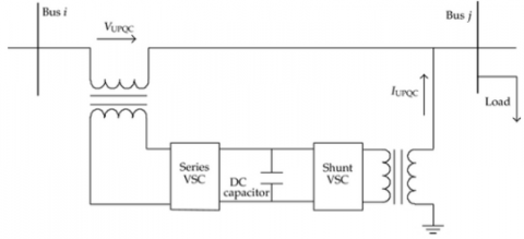
Figure 1 depicts the detailed construction of UPQC. Two voltage source inverters make up the UPQC, which is coupled by a common dc link capacitor. A series inverter connected to the line in series corrects voltage issues such as voltage sags and swells, flickering, and harmonics. The shunt inverter is linked shunt with the same AC line and handled as a current source to reduce current issues such as current harmonics, load reactive power, and management of the DC link capacitor voltage. Sharing active power between the two inverters is sped up by the DC link capacitor.
Figure 1. UPQC structure
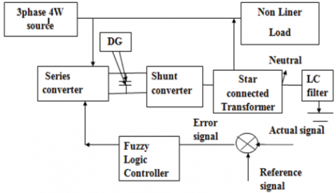
In this section the hybrid UPQC configuration has been illustrated. The suggested technique consists of a Y-connected transformer of lower rating. UPQC coupled with Distributed generator is connected with the transformer. The grid, with a 500 kVA capacity, serves as the three-phase source. A shared DC link and capacitor connect the series and shunt converters. In Figure 2, the suggested UPQC model is displayed. The DC link of this UPQC has the DG attached. The FLC is the foundation of the series converter control technique. The line compensates for the series converter's voltage sags and swells.
Figure 2. UPQC model(Proposed)
$I_L=\frac{2 v \sin^{\delta} / 2}{X} \frac{V_c}{X}$ (1)
The series converter model uses the power flow in the line, which is stated as (2).
$P=V I_L \cos (\delta / 2)$ (2)
where, magnitude of voltage is V is the angular frequency is δ, Line X's difference is the transmission line's series reactance. Shunt converter modeling uses the power balance equation, which is stated as (3).
$V_{d c} I_{d c}=\frac{3}{2}\left(E_{s R} I_{s R}+E_{s I} I_{s I}\right)$ (3)
A. Control for series converter
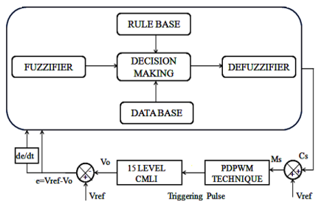
Figure 3. Control structure for fuzzy logic
The distribution system's voltage sags and swells as a result of numerous disturbances, including switching operations and other failures. Consumer goods are significantly impacted. The series converter corrects the distribution network's voltage sags and surges. Figure 3 depicts the FLC based controller for series converter. The comparator compares the measured voltage from the DC connection to the reference voltage. FLC 1 is used to handle the error signal produced by the comparator. The amplitude of the inserted voltage in the converters is used to process the true voltage in phases a, b, and c. Comparator compares this output value to FLC 1's output. For calculating reference current, the voltage's amplitude is employed. The three-phase detected voltage is used to calculate the voltage's amplitude, which is given in Eq. (4).
$v_{s m}=\left[\frac{2}{3}\left(v_{s a}^2+v_{s b}^2+v_{s c}^2\right)\right]^{\frac{1}{2}}$ (4)
where vsm denotes the source voltage's amplitude. The three-phase supply voltage is represented by Vsa, Vsb, and Vsc. The FLC 2 once more processes the erroneous signal coming from that comparator. PWM receives the FLC-2's output. The series converters adjust for voltage sags and swell based on the firing signals from PWM. The reference value of the injected voltage serves as the foundation for the adjustment of voltage sag and swelling. The system specification determines the reference value of the injected voltage. In Eqns. (5)-(7), the reference values of the injected voltage are expressed.
$v_{i a}=\sqrt{2} v_{i n j} \sin \left(w t+\delta_{i n j}\right)$ (5)
$v_{i b}=\sqrt{2} v_{i n j} \sin \left(w t+2 \frac{\pi}{3}+\delta_{i n j}\right)$ (6)
$v_{i n j}=v_s-v_l$ (7)
B. Shunt converter control
Contol of Shunt Converters Harmonics is generated by electronic equipment in distribution networks due to an increase in nonlinear load and power. The shunt converter corrects for these harmonics. A reference voltage and the detected DC link voltage are compared. The erroneous signal is corrected, and its magnitude is used as a reference for the three-phase supply current. Utilizing the in-phase unit vector and the authentic voltage supply, in-phase unit vector is obtained to compute the reference current for three phase as in Eq. (8).
$u_{s a}=\frac{v_{s a}}{v_{s m}}, u_{s b}=\frac{v_{s b}}{v_{s m}}, u_{s c}=\frac{v_{s c}}{v_{s m}}$ (8)
The division of magnitude by unit current vectors is taken from the three-phase supply current as a reference. The error value is then determined by comparing this reference current to the actual supply current. The acquired signal from error statistics is transformed into PWM waveforms. The shunt converter balanced the relation between the reactive power and harmonics in the distribution system based on the PWM signal received. The detailed nomenclature has been added in following Table 1:
Table 1. Detailed Nomenclature of the variables
|
Variable |
Nomenclature |
|
V |
Magnitude of the sorce voltage |
|
IL |
Load Current |
|
δ |
angular frequency |
|
X |
transmission line's series reactance |
|
Vdc |
DC offset voltage |
|
Idc |
DC offset Current |
|
EsR, EsL |
EMF |
|
vsm |
Source Voltage's amplitude |
|
Vsa, Vsb, and Vsc |
Supply voltage |
C. Fuzzy logic-controlled system
The FLC's input is the measured DC link voltage value. The fuzzification process transforms the voltage value into a fuzzy value. The input values are transformed into linguistic values, which may be thought of as labels for fuzzy sets, in this fuzzification process. The input signal measurement is construed as a fuzzy singleton in a fuzzy control system. Figure 3 shows the layout of the fuzzy logic controller (FLC) that the solar-powered H-Bridge multistage inverter uses to implement virtual reality. The output voltage (Vo) of the fifteenth-level inverter is acquired from its output, and it is then contrasted with the reference voltage (Vref), which is the preferred value that the inverter must attain per grid regulations. The variable error rate de/dt and the subsequent error, e = Vref - Vo, are the input parameters for the FLC, which is made up of five primary block sets. Wave generators, blurring, inference systems, rule bases, and databases are a few examples.
In member functions, fuzzification is used to transform input data into membership levels. The FLC compares the incoming control signal (or control signal) C with the voltage reference (Vef) PWM, which calls for the development of a modulated signal Ms that may be used as a trigger signal for the switches in the inverter's power transistor circuits. The problem centers on a mistake and its MF derivative.
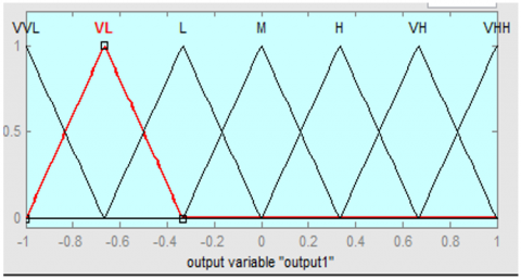
Figure 4 displays the MF of the incorrect signal. In this diagram, The fuzzy logic controller input's MF and the error signal's derivative are shown in Figure 4.
Figure 4. The membership function
As a reference signal generated by a membership function, fuzzy logic's output is depicted in Figure 5. One output and two inputs (the mistake and its derivative signal) are shown in a rule matrix in Table 2 (Reference signal). Following that, the fuzzy value is converted into a crisp value via a defuzzification procedure. The conversion was conducted using the center-of-gravity method. Table 2 discussed about the fuzzy logic controller rules. The matrix has two variable error signal and control signal. N stands for negative, P for positive, and Z is for zero. The letters B, M, S, and E all stand for different sizes of errors.
Table 2. FLC rule matrix
|
e CE |
NB |
NS |
NM |
ZE |
PB |
PS |
PM |
|
NB |
PB |
PB |
PB |
PB |
ZE |
PM |
PS |
|
NS |
PB |
PM |
PB |
PS |
NM |
ZE |
NS |
|
NM |
PB |
PB |
PB |
PM |
NS |
PS |
ZE |
|
ZE |
PB |
PS |
PM |
ZE |
NB |
NS |
NM |
|
PB |
ZE |
NM |
NS |
NB |
NB |
NB |
NB |
|
PS |
PM |
ZE |
PS |
NS |
NB |
NM |
NB |
|
PM |
PS |
NS |
ZE |
NM |
NB |
NB |
NB |
Figure 5. MF for the reference output
The fuzzy rule base assembly applies human control, knowledge, and information to the specified problem. Using a 7×7 matrix, the rule basis was created. The defuzzification method, which produces the crisp value from the fuzzy value, uses the centroid of area approach.
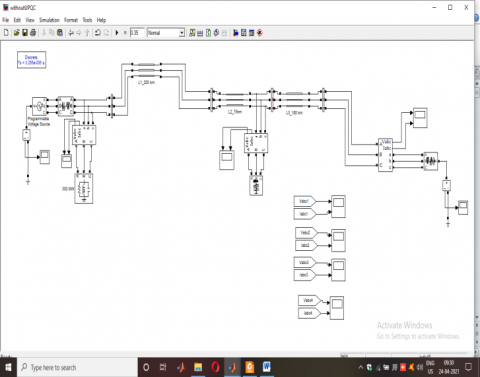
The suggested hybrid UPQC with DG has been simulated using MATLAB. The source voltages have been evaluated when UPQC is disconnected and connected eventually. It was observed that when UPQC is connected the source voltage is distorted. Unlikely, in other case, voltage waveform is pure sinusoidal in the presence of UPQC. Figures 7 and 12 depict the voltage waveform on the source side with and without UPQC, respectively. It has been unmistakably demonstrated that after attaching the UPQC, the voltage sag and swell present in the waveform are adjusted. Due to source-side compensation, the voltage sags and swells that are present on the load side are also lessened. Table 3 shows the simulation parameters used for simulation. The simulink diagram without UPQC has been demonstared as shown in Figure 6.
Table 3. Simulation parameters
|
Input voltage |
440V |
|
Input current |
20 Amps |
|
Frequency |
60Hz |
|
Load Voltage |
400V |
|
Load Current |
15Amps |
Figure 6. Simulation model without UPQC
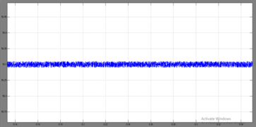
Figure 7. Voltage and current waveform without UPQC
Figure 8. THD value without UPQC
Figure 9. Neutral current (Source Side)
Figure 10. Neutral current (Load Side)
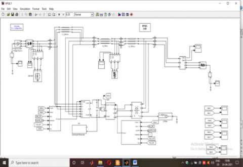
Figure 11. Simulation model with UPQC
Figure 12. Voltage waveform with UPQC
Figure 13. Neutral currents (a) Source side (b) Load side
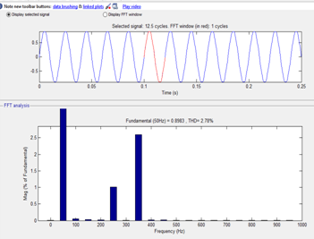
Figure 14. THD values with UPQC
It can be illustrated from Figure 7 that the current waveform obtained from the load side contains harmonics before connecting the UPQC. Figure 8 discussed about the total harmonic distrotion. Fundamental component has been described. The FFT has shown the detailed fourier of THD. Figure 9 discussed about the source side neutral current. Figure 10 interprets the load side neutral current. Load current harmonics are also present after connecting the UPQC. The similink connection diagram has been elucidated in Figure 11 and Figure 12. It demonstrates how the waveform's high-order harmonics are diminished once the UPQC is connected. Figure 13 demonstrated the neutral currents in source side and load side after using FLC and UPQC. Figure 14 shows the FFT window to calculate total harmonic distortion It is demonstrated that attaching the UPQC reduces the high-order harmonics that were present in the waveform. Both the source side and the load side of the system's harmonic distortion are examined. Before connecting the UPQC, the THD on the load side was 38.83 percent, as shown in Figure 8, and after connecting it with the DG as wind, it was 2.88% percent, as shown in Figure 14.
In this research work, the compensation technique has been proposed and presented for load current, source current and neutral current harmonics along with voltage sag/swell in distribution systems for a Y-connected transformer with low voltage rating-linked to hybrid unified power quality conditioner. The Y-connected transformer has the benefit of employing a minimal volt-ampere rating, which makes the cores affordable to construct and takes up little room. In-depth simulation studies have been used to examine the proposed UPQC's performance. It can be inferred from these investigations that the suggested approach completely correct the harmonics of the current at source side, load side as well as neutral., The harmonics are also minimized in voltage sag/swell, using the proposed scheme.
[1] Fatiha, M., Mohamed, M., Nadia, A.A. (2011). New hysteresis control band of an unified power quality conditioner. Electric Power Systems Research, 81(9): 743-1753. https://doi.org/10.1016/j.epsr.2011.05.003
[2] Ucar, M., Ozdemir, S. (2013). 3-Phase 4-leg unified series–parallel active filter system with ultracapacitor energy storage for unbalanced voltage sag mitigation. International Journal of Electrical Power & Energy Systems, 49: 149-159. https://doi.org/10.1016/j.ijepes.2013.01.005
[3] Mohammed, B.S., Rao, K.R., Ibrahim, R., Perumal, N. (2012). Performance evaluation of R-UPQC and L-UPQC based on a novel voltage detection algorithm. In 2012 IEEE Symposium on Industrial Electronics and Applications, pp. 167-172. Bandung, Indonesia. https://doi.org/10.1109/ISIEA.2012.6496621
[4] Watanakul, N. (2012). An application of wind turbine generator on hybrid power conditioner to improve power quality. IREE, 7: 5487-5495.
[5] Ara, A.L., Kazemi, A., Niaki, S.A.N. (2009). Improvement of phase shifting transformer operation by hybrid arrangement with UPFC. International Review of Electrical Engineering, 4(5): 1102-1109.
[6] Khadkikar, V. (2011). Enhancing electric power quality using UPQC: A comprehensive overview. IEEE transactions on Power Electronics, 27(5): 2284-2297. https://doi.org/10.1109/TPEL.2011.2172001
[7] Singh, B., Jayaprakash, P., Kothari, D.P. (2008). A T-connected transformer and three-leg VSC based DSTATCOM for power quality improvement. IEEE Transactions on Power Electronics, 23(6): 2710-2718. https://doi.org/10.1109/TPEL.2008.2004273
[8] Huang, S.J., Wu, J.C. (1999). A control algorithm for three-phase three-wired active power filters under nonideal mains voltages. IEEE Transactions on Power Electronics, 14(4): 753-760. https://doi.org/10.1109/63.774215
[9] Axente, I., Basu, M., Conlon, M.F., Gaughan, K. (2006). A study of shunt active filter generating the DC biased current. In Proceedings of the 41st International Universities Power Engineering Conference (UPEC). Northumbria University, Newcastle upon Tyne, UK, 6th -8th September 2006.
[10] Ghosh, A., Ledwich, G. (2003). Load compensating DSTATCOM in weak AC systems. IEEE Transactions on Power Delivery, 18(4): 1302-1309. https://doi.org/10.1109/TPWRD.2003.817743
[11] Basu, M. (2003). Some investigations on unified power quality conditioner (Doctoral dissertation, Ph. D. dissertation).
[12] Axente, I., Ganesh, J.N., Basu, M., Conlon, M.F., Gaughan, K. (2010). A 12-kVA DSP-controlled laboratory prototype UPQC capable of mitigating unbalance in source voltage and load current. IEEE Transactions on power Electronics, 25(6): 1471-1479. https://doi.org/10.1109/TPEL.2010.2040635