Abstract
The wide application range of simply supported beams in building construction, has always caused an attraction to somehow increase their bending capacity with high ductility. In this research, for the very purpose, the reinforcement bars under compression are bent at 45° from 1/3 of the beam length from the two ends and led to the tension zone. A sealed rubber tube of diameter twice that of the reinforcement bar covers the slanted part to separate it from the beam’s concrete. This will in fact reduce the stress intensity created in the bars above and below the neutral plane and increase the beam’s bending capacity considerably through making the two tensile and compressive forces acting opposite to each other. Actually, the proposed system can be specified by applying a superposition of the sum of the effects of the compressive stresses of the reinforcement bars above the beam’s 1/3 ends plus the sum of the effects of the tensile stresses created at 1/3 of the beam midpoint. The compressive stress created in the upper part tends to pass through the slanted part and reach the tensile part, and an opposite act for the tensile stress created in the lower part. Therefore, it is obvious that a compressive force found by the solution of the first superposition equation is applied at the middle 1/3 of the lower part and causes up to 25 % increase in the beam bending capacity.
1. Introduction
There are many techniques for increasing bending capacity. A post-tensioning system for reinforcing and creating a compressive force in the tensile member will cause a reduction in the ultimate tensile stress. some methods have been proposed to reinforce the tensile section to enhance the beam’s bending capacity. In this study use a new reinforcement, an auxiliary member, or a primary compressive force applied on the tensile section to enhance the bending capacity [1-3].
2. Literary systems for increasing bending capacity
Figeys et al. (2008) used the finite element method and studied a case in the laboratory where a post-tensioned FRP member stuck under a concrete beam. They compared two similar beams one simple and one reinforced with a tensioned FRP plate and concluded that the latter increased the beam bending capacity by about 40 %. Easy execution (compared with pretensioned cables), capability of being implemented after the beam has been constructed, and easier maintenance are the merits of such a system. Challal (1991) investigated fiber reinforced bars (FRB) and showed that they reduced cracks and increased the bending strength. Jerom and Ross (1999) showed that FRP-reinforced beams gained almost 30-70 % more bending strength, but lost about 40 % of their ductility [1, 4].
3. Proposed system for increasing bending capacity
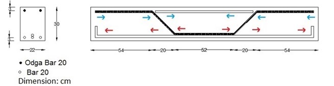
Fig. 1 shows that in an ordinary beam, the compressive and tensile stresses are created respectively above and below the neutral plane. In Fig. 2 that shows the new beam model, it is quite clear that the slanted reinforcement separated from the beam concrete can be a place where the compressive stress above can be transferred to the tensile reinforcement below. Fig. 2 that uses the superposition method, shows that the stress created in the compression zone and its transferring to the tensile zone can somewhat reduce the tensile stress created in the mid-beam tensile section; the reverse occurs too for the tensile stress created in the tensile zone. This resembles the case of pre-stressing which causes an increase in the beam bending capacity. In short, this method reduces the tensile stress of the beam’s mid-section and increases its bending capacity through transferring the compressive force created in the upper part of the concrete beam to its lower middle one-third where the tensile stress has its highest value.
Fig. 1Ordinary beam models. It shows number of compressive and tension reinforcement bars
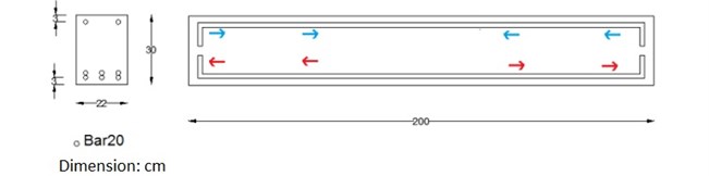
Fig. 2Superposition of the stress created in the bent reinforcement bar
Earlier studies show that some methods have been proposed to reinforce the tensile section to enhance the beam’s bending capacity. These studies use a new reinforcement, an auxiliary member, or a primary compressive force applied on the tensile section to enhance the bending capacity. The common point between the present and earlier researches is that this research too tries to present a new method of applying a compressive stress in the tensile zone to strengthen the tensile section.
4. Research methodology
To study accuracy and behavior of the proposed theory, use was made of the finite element (with the ABAQUS Software) and laboratory test methods. The beam specimens were built in IUST, Tehran, in Sept. 2014 and tested two months later in BHRC. The - diagrams were then drawn for two beam specimens with concentrated loads in the mid-span (Figs. 6-7).
In simulation, use was made of the damaged plastic concrete and specifications of the 30 MPa concrete for modeling in the ABAQUS Software. For reinforcement bars, both the elastic and plastic states were considered; the specifications used in the above software are shown in Fig. 3. The results are related to the bars extensometer tests performed at the laboratory of the School of Mechanics, IUST. In the steel-concrete interaction modeling, the embedded rigid element model was used and only the slanted part was excluded [5-10].
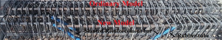
The ordinary and new laboratory specimens were made similar to their finite element counterparts, but before the concrete placement, the slanted bar was covered with a rubber tube and the two ends were sealed with glue to prevent the concrete to enter the tube (as shown in Fig. 4). Meanwhile, to compare the laboratory results and check their accuracy, two beam specimens were made for each model. The reinforced bars were of the A-III type and underwent the extensometer test [7].
Fig. 3Steel bar stress-strain diagram
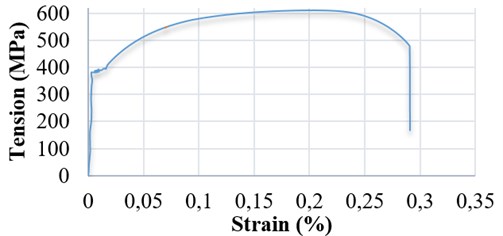
Fig. 4Reinforcements in the ordinary and new models (proposed models)
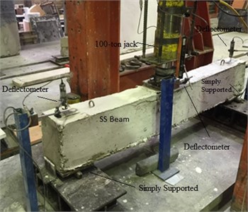
Next, the cubical specimens were tested in the BHRC structure laboratory under similar loading and boundary conditions; they were crushed on the test day and day 28 of the concrete age with a compressive strength of about 30 MPa and both the ordinary and new models were tested on day 30. A 100-ton jack was placed in the mid-span on a 20×20 cm metal plate; all the above mentioned arrangements are shown in Fig. 5. Up to the ultimate bending capacity in the elastic range, loading was static (100 kg/2 sec) after which, in the plastic range, it was changed to the displacement type (0.05 mm/2 sec) [7].
Fig. 5Beam below a 100-ton jack and location of the deflect-meter and test setup
When tests started, the beam mid-span load-displacement information was given to the data logger so as to compare the results (shown as - curves) with those found by ABAQUS. Comparisons of the results (beams with beams and laboratory tests with ABAQUS) confirm the accuracy of the proposed theory and modeling, and provide, for other researchers, the possibility of modeling, concluding, and validating this theory [7, 9].
5. Findings
One specimen from each finite element model and two from the test models were studied and the - curves were drawn to determine each model’s bending capacity and ductility. The bending capacity for the elastic, elastoplastic, and plastic (ultimate limit) states is shown by - curves [6].
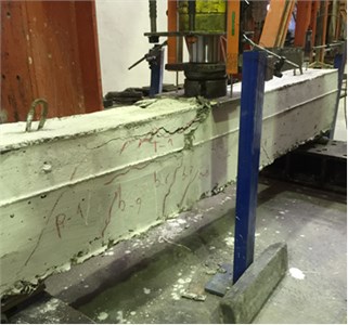
The - results and both the finite element (ABAQUS) and laboratory tests static analyses show that the ultimate bending capacity of the new model beam is 25 % more than that of the ordinary beam. This is clear in Figs. 6 and 7 which compare the - results of the two beam models; therefore, the conformity of the - results of the laboratory tests and finite element findings show the accuracy of the ABAQUS model before and up to the ultimate bending capacity. The - results of the new model’s laboratory tests show that after 25 % increase, the bending capacity starts decreasing due to the area reduction (where steel and concrete separate) and beam shear capacity reduction in this part due to excess loading. Figs. 8 show crack formation in the new model’s ultimate limit and failure time [9].
Fig. 6Comparison of the modified results of the ordinary and new models specimens in the ABAQUS [9]
![Comparison of the modified results of the ordinary and new models specimens in the ABAQUS [9]](https://static-01.extrica.com/articles/18544/18544-img6.jpg)
Fig. 7Ordinary and new models’ laboratory tests results’ p-Δ curves
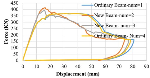
Fig. 8New model’s cracks (ultimate shear capacity)
6. Conclusions
Although pre-tensioning with cables and post-tensioning with the help of FRP plates stuck to the beam are quite efficient and safe systems, the stress transfer can, through more studies, be another way of increasing the bending and load bearing capacities in structural engineering. We suggest that other researchers study and do researches on this structural engineering-related subject. In general, the results of our research and the suggestions we have for other colleagues are as follows:
1) To increase the bending capacity of a simply supported beam through transferring the compressive stress of the compressive reinforcement to the tensile reinforcement, there is a weak point around the rubber tube. To eliminate this, we suggest increasing stirrups and the beam cross sectional area in this part.
2) Stress transfer from compressive to tensile reinforcement can be an initiation for the subject of “bending capacity increase in concrete beams”. In general, compressive stress transfer to the tensile part from any beam section possible can result in an increase in the bending capacity. It is suggested that in simply supported beams the rubber tube (hose) be placed at the turning point and the investigations and tests be repeated.
3) To optimize the proposed system, it is suggested that more research be done on such topics as the bars yielding, point and angle of bending, and so on. Most probably, if the compression bar is bent towards the beam’s tensile section at its yielding point, the bending capacity increase will be more, but this needs more research.
References
-
Figeys W., Verstrynge T. E., Brosens T. K., Van Schepdael L., Dereymaeker J., Van Gemert D., Schueremans L. Feasibility of a novel system of prestressing externally bonded. Materials and Structures, Vol. 44, Issue 9, 2011, p. 1655-1669.
-
Loo Y. C., Chowdhury S. H. Reinforced and Prestressed Concrete. Vol. 1, 2010.
-
Khalou A. R. Design of Prestressed Concrete Structures. Vol. 1, 2003.
-
Oehlers D. J., Liu I., Seracino R. A. Generic design approach for EB and NSM longitudinally plated RC beams. Constructions and Building Materials, Vol. 21, Issue 4, 2007, p. 697-708.
-
Massart T. J., Vantomme J., Bouillard F., Iribarren B. S. Progressive Collapse Simulation of Reinforced Concrete Structures; Influence of Design and Material Parameters and Investigation of Strain Rate Effects. Ph.D. Thesis, Royal Military Academy Polytechnical Faculty, Universite Libre de Bruxelles Faculty of Applied Sciences, Bruxelles, 2010.
-
Jankowiak T., Lodygowski O. Identification of Parameters of Concrete Damage Plasticity Constitutive Model Foundation of Civil and Environmental Engineering. Pozan, Poland, 2005.
-
Mostofinezhadm D. Reinforced Concrete Structures. Based on ACI318-05, Vol. 1, 2007.
-
Schreppers G. J. Embedded Reinforcements. TNO DIANA, Netherland, 2011, p. 11-15.
-
ABAQUS CAE/6.13-4 Version.
-
ABAQUS Theory Manual. Version 6.3, Hibbitt Karlson and Sorensen, Inc., 2002.
Cited by
About this article

The authors declare that they have no conflict of interest.
