Investigation of Standalone Solar Photovoltaic Water Pumping System With Reduced Switch Multilevel Inverter
 T. Poompavai
  M. Kowsalya*
- School of Electrical Engineering, VIT University, Vellore, India
Solar photovoltaic-powered water pumping systems are becoming very successful in regions where there is no opportunity for connecting the electric grid. The photovoltaic technology converts solar energy into electrical energy for operating direct current (DC) or alternating current (AC) motor-based water pump. In the case of a solar AC motor water pump, it engages two energy conversion stages (DC–DC and DC–AC) in the power conditioning unit. This usually resulted in increased size, cost, and complexity and decreases the efficiency of the entire system. The existing two-level inverter (DC–AC) stage generates higher harmonics in output voltage and higher electromagnetic interference that deteriorates directly the AC motor performance. Therefore, as a solution to the addressed problems, in this study, an innovative seven-level inverter with five power semiconductor switches for the operation of 0.5 HP single-phase induction motor pump had been investigated. The proposed multilevel inverter has the capability of providing lesser harmonic voltage that reduces filter requirements; along with this, other part components are used lesser when compared to other conventional multilevel inverters. To provide better insight into the work performance of this proposed topology, the simulation is executed in the MATLAB/Simulink environment, and hardware implementation of the same is depicted. From the results, it is observed that the proposed multilevel inverter topology obtained a total power loss of 1.6034 W and efficiency at 98.11%. This quality output voltage acquired from the multilevel inverter had been fed to drive the induction motor water pump; it pumped the water at the desired flow rate accordingly.
Introduction
Globally, solar photovoltaic-powered water pumping systems (SPVWP) are progressively used in the areas where there is plentiful sunshine and scarce power generation systems. Besides, photovoltaic (PV) system hardware prices declined to 80% in the last two decades. In the last 10 years, the levelized cost of electricity (LCoE) measure has lowered by 75% to USD 69/MWh (Jäger-Waldau, 2019). These developments paved the way to enroll PV systems much faster, especially the standalone alone PV systems. The acquisition of SPVWP is very simple compared to other conventional diesel or electric-based water pumping systems in consideration of cost and maintenance. Generally, SPVWP is an assembly of a solar PV array, inverter, and motor-pump set. A PV array is a combination of electrically wired solar cells; they are mounted together on a frame, whereas an array is designed by connecting several modules together. The solar inverter is an important building block in a PV system, which makes the conversion of direct current (DC) output from PV panel into alternating current (AC) current that is able to run a motor pump set for groundwater extraction (Biswas and Iqbal, 2018). In addition, the present SPVWP utilizes electronic systems, which majorly helps in increasing output power, efficiency, and performance of the whole system. The controller also has the capability to track water levels in a tank, control motor speed, and utilize maximum power point tracking technology to give efficient output (Poompavai and Kowsalya, 2019). Furthermore, the authors in Odeh et al. (2018) suggested that the performance of SPVWP strongly depends on the head of the operation, irradiance factor, and PV array size. To improve the efficiency of the pump, they recommended to design the pump based on pump-well characteristics, subsystem efficiency, array sizing, average of system, frequency distribution of irradiance, etc. (Al-Shetwi et al., 2016). The advancements also occurred in PV panel tracking mechanism, from manual tracking to automatic dual-axis tracking systems, with the help of microcontroller programming (Chandel et al., 2015).
In SPVWP, the power conditioning unit (PCU) comprises of all electronic conversion units. Therefore, in the PCU unit, if the system employs a DC–DC converter or DC–AC inverter alone, this is regarded as a single-stage system. Else, if the system employs both converters, this is considered as a double-stage system (Karampuri et al., 2014). In a double-stage system, two PCUs are interfaced: one is applied for extracting maximum power from PV source, and the other is used for controlling a motor pump set. The existing two-level inverter or voltage source inverter (VSI) in PCUs is required to satisfy power quality issues, and it is also found to increase the losses and ripple content in the motor current of the PV system that leads to increased value of filter circuitry (Ramulu et al., 2016). Therefore, there is a requirement of single-stage power conditioning (i.e., single PCU) solution for SPVWP where the inverter is capable of generating more than the two-level voltage in the output (Packiam et al., 2013; Mishra and Singh, 2016, 2018). Multilevel inverters (MLIs) provide the ultimate solution for the addressed issue and capable of delivering high power and medium voltage for industrial applications (Kurtoglu et al., 2019). Moreover, MLI extracts lesser input current functions both at the higher and lower switching frequency, gives lesser dv/dt effects in the load side, and also reduces filter needs that leads to avoiding stresses in bearings of a motor (Poompavai and Vijayapriya, 2017). As of now, many MLI topologies are available based on the mechanism of switching and depending on the input source voltage. Of those, the major three topologies commercially preferred in industries are cascaded H-bridge (CHB) multilevel inverter, diode clamped and flying capacitor type (Akagi, 2017).
The renewable energy-based systems usually take the foremost cascaded H-bridge type since it involves more isolated DC sources (Amamra et al., 2017) and also it eliminates fluctuation problems and the need of additional clamping diodes and flying capacitors. However, the issue with this kind is the switch count; it increases whenever the number of voltage level increases, which results in a bulky, less efficient and most expensive inverter. In an effort to fix this issue, different MLI topologies with reduced switch count had been analyzed (Gupta et al., 2016; Siddique et al., 2019a,b). This type of topologies greatly reduces the requirements of the driver circuit and lowers the size and expense of the entire system. Focusing on this reduced switch count to a maximum and minimizing the complexity, a novel topology was introduced (Umashankar et al., 2013). It utilized only five switches for a seven-level inverter, and this is the very least possible reduction in switch count when compared to other proposed topologies. The quality output voltage generated from the topology could be able to drive an asynchronous motor. To fulfill the water supply needs, induction motors are generally chosen for water pumping operation. Furthermore, the production of induction motors is in a mature stage paving a way to use it in developing countries for SPVWP application. The major advantages of induction motor include high starting torque, less cost durability, speed variation, low maintenance cost, easier operation, etc. This induction motor is followed by a centrifugal pump for pumping operation. The speed and flowrate are regulated with the help of multilevel inverters with minimum total harmonic distortion (THD). Al-Shetwi and Sujod (2018) found an inverse relationship between solar irradiance and THD; they observed that whenever there is an increase in solar irradiance, the THD tends to decrease either in the current and voltage waveform. The quality output voltage waveform obtained from MLI could be controlled, with its magnitude and frequency referred to be V/f control. This way permits the induction motor to attain the desired speed at different rates.
In this study, the operation of a seven-level inverter with five switches inverter had been tested experimentally with 0.5 HP single-phase induction motor water pump with the help of d-SPACE RTI-1104 platform. This topology uses an insulated-gate bipolar transistor (IGBT), as power switches and gate signals are given through a sinusoidal pulse width modulation technique. This proposed system eliminates the need for the DC–DC conversion stage in SPVWP and provides a single-stage solution through the MLI topology. The observed results show that the induction motor pump stayed its operation smoothly by receiving quality output voltage with lesser THD and also with reduced switching losses from seven-level five-switch topology. The speed and flowrate are regulated at the desired value with the help of pulses obtained from the proposed MLI topology.
A Framework of the Proposed System
The solar PV standalone water pumping system framework is depicted in Figure 1. It comprises of a PV array, followed by a five-switch seven-level inverter and an induction motor water pump. The proposed multilevel inverter with reduced switches is used to provide pulse width modulated voltage to the input of induction motor and pump assembly with a single-stage solution.
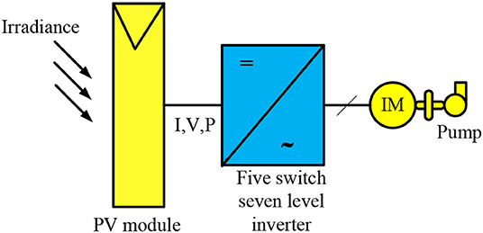
Figure 1. A framework of the proposed system.
Photovoltaic System
The photovoltaic cells are made of customized PN junction diode that converts the visible light into DC, and this process is referred to as photovoltaic effect. The PV modules combined in parallel or series to generate higher voltage and currents (Aliyu et al., 2018). The PV unit can be represented by two model: single diode model (SDM) and the double diode model (DDM) (Jordehi, 2016; Sudhakar Babu et al., 2016). The SDM model is the most prevailed model that has less complexity and achieve accurate results.
It represents the individual PV cell; a PV module consists of many cells or an array that includes many modules together. The mathematical equation describing the PV system is expressed in Equation (1).
where Ipv is the current produced by incident light (A), Io is the leakage current of a diode (A), q is the charge of an electron (1.60217 × 10⁻¹⁹C), k is the Boltzmann constant (1.38065 × 10⁻²³ J/k), α is the diode ideality constant (1 < α < 1.5), Rs is the equivalent PV array series resistance (Ω), Rp is the equivalent PV array parallel resistance (Ω), Nser is the number of cells in series, Npar is the number of cells in parallel, T is the PN junction temperature (K), and Vt is the PV array thermal voltage (V).
PV-Fed Multilevel Inverter With Reduced Switch Count
The seven-level inverter with five-switch topology representation is given in Figure 2. It is a very simple topology that involves four isolated DC sources, and in the case of nine levels, it would be five DC sources and so on. Since it has isolated DC sources integrating PV as a source is very easy. In this proposed topology, the PV panels replaced those isolated DC sources. Using phase opposition and disposition (POD) technique (Dan et al., 2015), the gating signals are generated and given to the five power IGBT switches. A sinusoidal modulating signal having a magnitude of “Am” and frequency of “f m” is taken to generate the gate signal where comparison is made in between reference and the carrier waves. The signals produced would be equal to the number of carrier signals. The modulation index (Ma) can be represented by
Initially, the first leg of switches St1, St2, and St3 had to be fetched with 2 kHz switching frequency followingly the second leg of switches St4 and St5 that should be fed with 50 Hz frequency. The gating signal pattern of the first leg of the switches must be unidirectional; otherwise, the output waveform may get distorted. The second leg of inverter assures the polarity reversal pattern. The switching pattern for the proposed topology is presented in Table 1. From the proposed topology, the seven-level output voltage levels are obtained with the combination of this five-switch operation. The final output voltage levels produced by the topology can be represented by m = (2 × n – 3), where “m” denotes the number of output voltage levels and “n” refers to the number of power switches. The expression can also be referred by m = (2 × v – 1), where “v” refers to the number of DC sources.
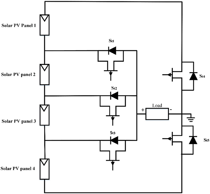
Figure 2. Photovoltaic (PV)-fed seven level inverter with five switches.
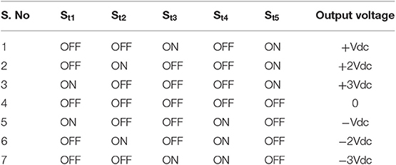
Table 1. Switching pattern of seven-level inverter with five switches.
Induction Motor-Driven Water Pumping System
In a wider range, induction motor is applied in domestic and industrial applications since they are of lower cost and need lesser maintenance. In general, induction motors are of symmetrical rotor cage and two non-symmetrical stator winding (main winding and auxiliary winding with starting or running capacitor), supplied with an equivalent sinusoidal voltage source. In this context, the second type had been chosen for water pumping applications. For modeling and analyzing the single-phase induction motor, two methods are available: one is the double field revolving theory, and the other is the cross-field theory. Of those, the first one is preferred often since it is more akin to the three-phase induction motor theory. In context to the theory, a part of alternating quantity can be resolved into two axes that are able to rotate in relatively opposite directions. Meanwhile, the axes of both stator windings are orthogonal as illustrated in Figure 3. Thus, the dq axes of the model may be associated with axes of windings. The basic equations that describe the model of induction motor are given below.
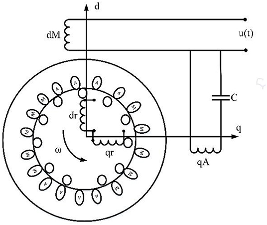
Figure 3. Perspective of dq model representation for single-phase induction motor.
The current flow through the stator is expressed as
If the current drawn by the rotor as I2, then the no-load current can be expressed by
The voltage across the rotor inductance is given by
The airgap power developed by the induction motor is given by
The motor torque is given by
The load balance equation is expressed by
whenever the load increases, the rotor current of the induction motor tends to increases. Furthermore, the energy generated from an induction motor is converted into kinetic energy in the liquid flow by triggering the liquid revolution. The centrifugal pump is used for pumping operation due to easy operation. It is particularly intended for fixed head applications, and the pressure difference generated increases along with the speed of the pump. These pumps are a rotating impeller category that radially throws water at a casing to transform water momentum into useful pressure.
Simulation Results and Analysis
Simulations conducted with MATLAB/Simulink environment to verify and confirm whether the proposed multilevel inverter topology can be practically suitable to solar photovoltaic-powered water pumping system or not. Using PV modeling, the IV and PV characteristics obtained for the Solyndra SL-001-200 PV panel, taken at different irradiance conditions, is represented in Figures 4, 5. The maximum open-circuit voltage (Voc) of 99.7 V is obtained at the standard irradiance condition of 1,000 W/m2. At minimum irradiance of 200 W/m2, Voc is developing at the range of 84 V. At some point of combination of the current and voltage, the power reaches a maximum value, which locates as Imp and Vmp. In this specific point, the maximum power produced is referred to as maximum power or MPP. The solar PV panel specifications are given in Table 2.
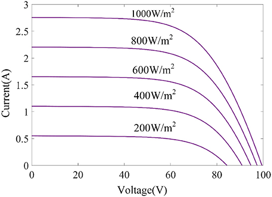
Figure 4. IV characteristics of Solyndra SL-001-200 photovoltaic (PV) panel.
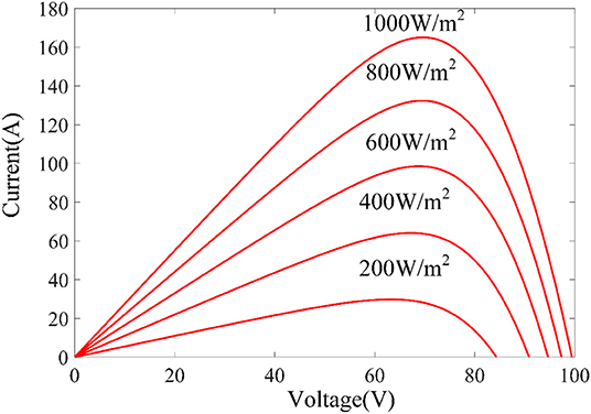
Figure 5. Photovoltaic (PV) characteristics of Solyndra SL-001-200 PV panel.
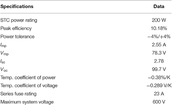
Table 2. Solyndra SL-001-200 (200 W) solar photovoltaic (PV) panel specifications.
Following that, using POD technique, the gate pulses are generated for power switches of proposed MLI topology. Based on the pulse pattern, the resulted seven-level output voltage and current attained from multilevel inverter topology is depicted in Figures 6, 7. The fast Fourier transform (FFT) analysis for the proposed topology is given in Figure 8. As per the Institute of Electrical and Electronics Engineers (IEEE) 519 harmonic distortion standard, for inverter without a filter in the circuit, 15–25% of THD is allowable. Accordingly, the least THD of 2.63% is developed in the resulted voltage. In case the proposed topology is designed with filter, it may achieve far better results. The logical expression for THD can be expressed by
where V1rms denotes the root mean square (RMS) value of the fundamental component, which is slightly high because of lower switching losses obtained from the proposed topology. The total power loss in an inverter is the combination of conduction (PC) and switching loss (PSw). The expression of total power losses occur in an inverter is given by
By considering the losses, the efficiency of the inverter can be calculated using the following expression,
Hence, considering both the losses calculated for each switch of the proposed inverter is represented in Figure 9. The second leg of switches attained lesser switching losses compared to the first leg because of utilizing lesser switching frequency. The total power loss calculated with the proposed multilevel inverter is 1.6034 W. The efficiency gained for the proposed inverter is 98.11%, whereas the conventional two-level inverter attains only 59.96%. The number of part count comparative analysis of existing and proposed topology is depicted in Figure 10. It shows that the proposed one stands far better than the others. The generated output voltage carrying lesser harmonic content is fed to the capacitor, then the capacitor-run single-phase induction motor drive is started to give its striking dynamic performance, which is depicted in Figure 11.
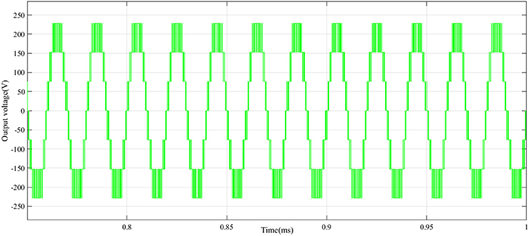
Figure 6. Seven-level output voltage from seven-level inverter with five switches.
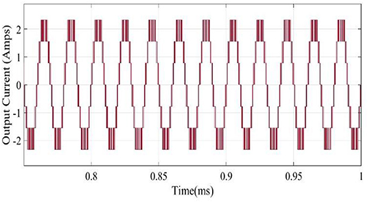
Figure 7. Output current from seven-level inverter with five switches.
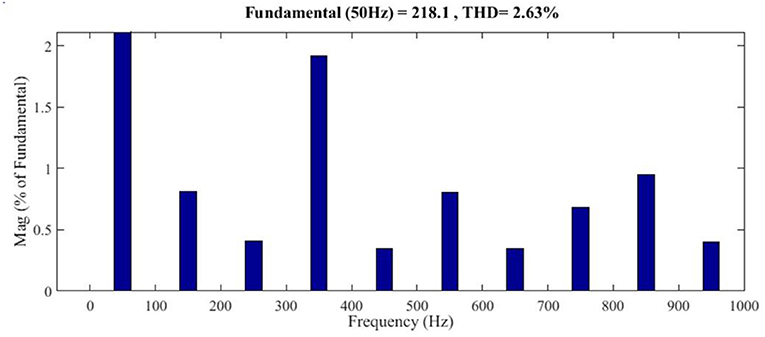
Figure 8. Fast Fourier transform (FFT) analysis of seven-level inverter with five switches.
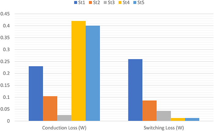
Figure 9. Power loss analysis for seven-level inverter with five switches.
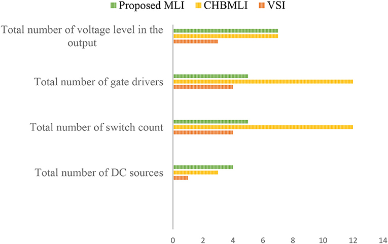
Figure 10. Comparison of part count in proposed multilevel inverter (MLI) and others.
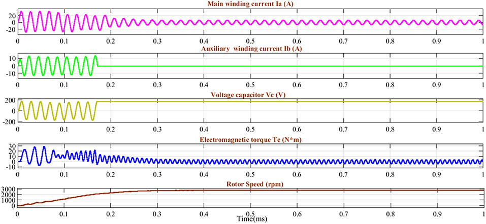
Figure 11. Dynamic performance of single-phase induction motor fed by seven-level inverter with five switches.
Experimental Validation
The hardware prototype for the proposed seven-level five switch inverter fed with a single-phase induction motor water pump had been tested experimentally. The gate signal generated through POD technique had been brought out with the help of digital I/O ports in the d-SPACE RTI-1104 platform. Then, it is passed to the TLP 350 gate driver board and to the power IGBT switches. The triggering of switches could happen only if the gate driver board enhances the voltage from 5 to 15 V. A switching frequency of 2 kHz had been applied to the first leg of three switches, and 50 Hz had been given to the other two switches. This kind of pulse pattern helps to reduce the switching losses significantly. To emulate or approximate the PV source equivalence, a small resistance is connected between the programmable DC supply and the seven-level inverter five switches. The input RMS voltage of 78.3 V and current of 1 A were given as input to the four-DC source input side for the topology from programmable DC supplies, which is fixed to operate at constant voltage mode. As a result, the final output of the seven-level voltage generated at the output side with lesser harmonics, as shown in Figure 12, is finally fed to the 0.5 HP single-phase induction motor water pump load that is able to run at a maximum speed of 2,880 rpm. Initially, the auxiliary winding disconnected at 75% of rated synchronous speed. The settled torque of 4 Nm is unidirectional to pertain to the motor in a single direction. Meanwhile, after a certain acceleration, the offset in torque generated by the motor decreases to a load torque. Subsequently, the control of torque, direction of rotation, and speed of the motor are decided by the voltage and frequency of the proposed multilevel inverter. The THD analysis obtained at the hardware side is depicted in Figure 13. It can be noted that the harmonic plots of current and voltage are maintained at the same frequency window. Furthermore, the seven-level output voltage and current pattern are similar to those attained from simulation results.
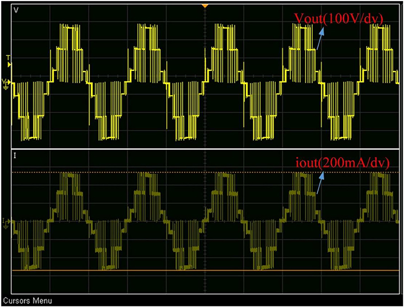
Figure 12. Output voltage and current of seven-level inverter with five switches.
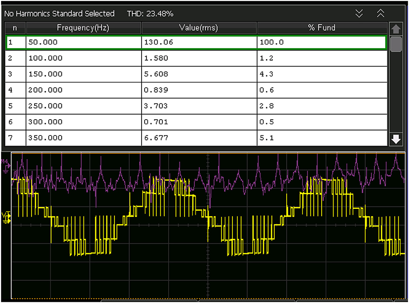
Figure 13. Harmonics generated in seven-level inverter with five switches.
Conclusion
The seven-level inverter with five switches had been applied for the investigation of a 0.5 HP single-phase induction motor water pump. The reduced switch count, lesser requirement of gate driver circuits and DC sources, and increased voltage levels in the output are the main features of the proposed multilevel inverter topology. As a promising source, the photovoltaic system could be able to give constant voltage to the reduced switch multilevel inverter input DC source side that guarantees the standalone operation of a water pump. In summary, the simulation results reveal that the switching losses calculated across each switch are less and the THD content is also very low without any filter compared to other conventional multilevel inverter topologies. The reduced harmonic content in the output voltage enabled the induction motor to deliver its striking dynamic performance, and it pumped water at the desired flowrate with the control in PWM technique. The hardware implementation of the same setup matched with the simulation outcomes, which validate the system, although when implementing practically, thermal resistance and leakage current in the circuit affects the power quality, which differentiates the simulation and practical results. The internal resistance of the auxiliary circuit (gate driver board) used to drive the IGBT also tends to create a difference among the simulation and practical results. The overall system performance found to be satisfactory for operating induction motor water pump, thereby validating the system model.
Data Availability Statement
The raw data supporting the conclusions of this article will be made available by the authors, without undue reservation, to any qualified researcher.
Author Contributions
TP and MK conceived of the presented idea. TP executed simulation and experiment analysis. MK encouraged TP to investigate and supervised the findings of this work. All authors discussed the results and contributed to the final manuscript.
Conflict of Interest
The authors declare that the research was conducted in the absence of any commercial or financial relationships that could be construed as a potential conflict of interest.
References
Akagi, H. (2017). Multilevel converters: fundamental circuits and systems. Proc. IEEE 105, 2048–2065. doi: 10.1109/JPROC.2017.2682105
Aliyu, M., Hassan, G., Said, S. A., Siddiqui, M. U., Alawami, A. T., and Elamin, I. M. (2018). A review of solar-powered water pumping systems. Renew. Sustain. Energy Rev. 87, 61–76. doi: 10.1016/j.rser.2018.02.010
Al-Shetwi, A. Q., and Sujod, M. Z. (2018). Harmonic distortion and voltage imbalance study of photovoltaic power plant connected to the malaysian grid. J. Telecommun. Electron. Comput. Eng. 10, 1–6.
Al-Shetwi, A. Q., Sujod, M. Z., Al Tarabsheh, A., and Altawil, I. A. (2016). Design and economic evaluation of electrification of small villages in rural area in yemen using stand-alone PV system. Int. J. Renew. Energy Res. 6, 289–298.
Amamra, S.-A., Meghriche, K., Cherifi, A., and Francois, B. (2017). Multilevel inverter topology for renewable energy grid integration. IEEE Trans. Ind. Electron. 64, 8855–8866. doi: 10.1109/TIE.2016.2645887
Biswas, S., and Iqbal, M. T. (2018). Dynamic modelling of a solar water pumping system with energy storage. J. Sol. Energy 2018, 1–12. doi: 10.1155/2018/8471715
Chandel, S. S., Nagaraju Naik, M., and Chandel, R. (2015). Review of solar photovoltaic water pumping system technology for irrigation and community drinking water supplies. Renew. Sust. Energy Rev. 49, 1084–1099. doi: 10.1016/j.rser.2015.04.083
Dan, H., Peng, T., Su, M., Sun, Y., Zhang, G., and Xiong, W. (2015). Implementation of phase disposition modulation method for the three-level diode-clamped matrix converter. IET Power Electron. 8, 2107–2114. doi: 10.1049/iet-pel.2014.0887
Gupta, K. K., Ranjan, A., Bhatnagar, P., Sahu, L. K., and Jain, S. (2016). Multilevel inverter topologies with reduced device count: a review. IEEE Trans. Power Electron. 31, 135–151. doi: 10.1109/TPEL.2015.2405012
Jäger-Waldau, A. (2019). Snapshot of photovoltaics—February 2019. Energies 12:769. doi: 10.3390/en12050769
Jordehi, A. R. (2016). Parameter estimation of solar photovoltaic (PV) cells: a review. Renew. Sust. Energy Rev. 61, 354–371. doi: 10.1016/j.rser.2016.03.049
Karampuri, R., Jain, S., and Somasekhar, V. T. (2014). “A single-stage solar PV power fed open-end winding induction motor pump drive with MPPT,” in: 2014 IEEE International Conference on Power Electronics, Drives and Energy Systems (PEDES) (IEEE), 1–6.
Kurtoglu, M., Eroglu, F., Arslan, A. O., and Vural, A. M. (2019). Recent contributions and future prospects of the modular multilevel converters: a comprehensive review. Int. Trans. Electr. Energ. Syst. 29:e2763. doi: 10.1002/etep.2763
Mishra, A. K., and Singh, B. (2016). “A single stage solar PV array based water pumping system using SRM drive,” in 2016 IEEE Industry Applications Society Annual Meeting.
Mishra, A. K., and Singh, B. (2018). Grid interactive single stage solar powered water pumping system utilizing improved control technique. IEEE Trans. Sustain. Energy 11, 304–314. doi: 10.1109/TSTE.2018.2890670
Odeh, I., Yohanis, Y. G., Norton, B., Alsoud, M., and Odeh, D. (2018). Long-term field operation of photovoltaic solar water pumps. Int. J. Ambient Energy 39, 467–476. doi: 10.1080/01430750.2017.1318792
Packiam, P., Jain, N. K., and Singh, I. P. (2013). Microcontroller-based simple maximum power point tracking controller for single-stage solar stand-alone water pumping system. Prog. Photovoltaics Res. Appl. 21, 462–471. doi: 10.1002/pip.1207
Poompavai, T., and Kowsalya, M. (2019). Control and energy management strategies applied for solar photovoltaic and wind energy fed water pumping system: a review. Renew. Sustain. Energy Rev. 107, 108–122. doi: 10.1016/j.rser.2019.02.023
Poompavai, T., and Vijayapriya, P. (2017). Comparative analysis of modified multilevel DC link inverter with conventional cascaded multilevel inverter fed induction motor drive. Energy Procedia 117, 336–344. doi: 10.1016/j.egypro.2017.05.140
Ramulu, C., Sanjeevikumar, P., Karampuri, R., Jain, S., Ertas, A. H., and Fedak, V. (2016). A solar PV water pumping solution using a three-level cascaded inverter connected induction motor drive. Int. J. Eng. Sci. Technol. 19, 1731–1741. doi: 10.1016/j.jestch.2016.08.019
Siddique, M. D., Mekhilef, S., Shah, N. M., and Memon, M. A. (2019a). Optimal design of a new cascaded multilevel inverter topology with reduced switch count. IEEE Access 7, 24498–24510. doi: 10.1109/ACCESS.2019.2890872
Siddique, M. D., Mekhilef, S., Shah, N. M., Sarwar, A., Iqbal, A., Tayyab, M., et al. (2019b). Low switching frequency based asymmetrical multilevel inverter topology with reduced switch count. IEEE Access 7, 86374–86383. doi: 10.1109/ACCESS.2019.2925277
Sudhakar Babu, T., Prasanth Ram, J., Sangeetha, K., Laudani, A., and Rajasekar, N. (2016). Parameter extraction of two diode solar pv model using fireworks algorithm. Solar Energy 140, 265–276. doi: 10.1016/j.solener.2016.10.044
Keywords: multilevel inverter, THD, DC-DC, DC-AC, photovoltaic, PWM, switching frequency, induction motor
Citation: Poompavai T and Kowsalya M (2020) Investigation of Standalone Solar Photovoltaic Water Pumping System With Reduced Switch Multilevel Inverter. Front. Energy Res. 8:9. doi: 10.3389/fenrg.2020.00009
Received: 02 December 2019; Accepted: 15 January 2020;
Published: 21 February 2020.
Edited by:
Umashankar Subramaniam, Prince Sultan University, Saudi ArabiaReviewed by:
Ali Q. Al-Shetwi, Universiti Tenaga Nasional, MalaysiaChiranjit Sain, Siliguri Institute of Technology (SIT), India
Copyright © 2020 Poompavai and Kowsalya. This is an open-access article distributed under the terms of the Creative Commons Attribution License (CC BY). The use, distribution or reproduction in other forums is permitted, provided the original author(s) and the copyright owner(s) are credited and that the original publication in this journal is cited, in accordance with accepted academic practice. No use, distribution or reproduction is permitted which does not comply with these terms.
*Correspondence: M. Kowsalya, mkowsalya@vit.ac.in