Droop and Oscillator Based Grid-Forming Converter Controls: A Comparative Performance Analysis
 M. A. Awal
 Hui Yu
 Srdjan Lukic
  Iqbal Husain
- FREEDM Systems Center, North Carolina State University, Raleigh, NC, United States
Two distinct approaches, one droop-based phasor-domain modeled and the other non-linear oscillator-based time-domain modeled, have emerged for the analysis and control of power electronic converters at the system interface layer where these converters are integrating distributed energy resources (DERs). While the droop-type controllers are based on distinct time-scale separation of control loops, purposefully slowing down the response of the DERs, the oscillator-based controllers deliver fast dynamic response with accurate power sharing capability as well as stability guarantee. In this paper, we analyze both the droop- and oscillator-type converters in the context of grid forming converters with respect to steady state terminal response, transient stability, and harmonic compensation in converter output current or in network voltage. Simulation and experimental results are provided to demonstrate the easier implementation of oscillator-based controls that can also achieve supplementary control objectives pertinent to power quality.
1. Introduction
The increasing penetration of power electronics converters and renewable energy resources into the power system presents a plethora of system level challenges both from analysis and control perspectives. Two distinct trends have emerged in the research community. On one side of the control spectrum, a significant effort is observed to achieve faster dynamic responses from the local controllers in the power electronics converters; these local controllers are essentially tracking controllers with an objective to track specific voltage, current, or power references. Faster dynamic response and accuracy of tracking typically drive such research efforts such as model predictive control, fuzzy control and direct power control (Cortes et al., 2008; Duong et al., 2018a; Gui et al., 2018). However, from a system-level perspective, coordination of these ever-increasing numbers of distributed resources pose a major challenge. Consequently, on the other side of the spectrum, another class of control methods has emerged, which essentially slows down the response of the distributed resources. For instance, virtual synchronous machine-based (Beck and Hesse, 2007; Chen et al., 2011; Zhong and Weiss, 2011; Qing-Chang Zhong et al., 2014; Liu et al., 2016; Zhong, 2017) or universal droop-control-based methods (Zhong and Zeng, 2016) emulate virtual inertia, which leads to slower system response. Inspired by the proven engineering knowledge gathered from the operation of the bulk power system, droop-based methods have been adopted heavily in power electronics dominated systems over the past decade (Vasquez et al., 2009; Kim et al., 2011; Yao et al., 2011; Rocabert et al., 2012; Han et al., 2015, 2016; Sun et al., 2017). However, three major challenges remain for droop-based systems. First, droop-based methods require a phasor approximation of the converter terminal voltages and are not well-defined in the super-synchronous time scale (Colombino et al., 2019); effectively, any analysis is valid only around a periodic sinusoidal trajectory. From an analytical point of view, this constitutes a major setback in networks with low inertia, which include all of the power electronics dominated systems. Second, a droop-controlled converter typically employs cascaded control structure including inner voltage and current control loops (Guerrero et al., 2011, 2013; Mohamed and Radwan, 2011; Han et al., 2017a,b). Distinct time-scale separation, at least an order of magnitude, is required between successive control loops. For high-power applications with low switching frequencies, such time-scale separation is difficult to achieve. Third, cascaded control loops are difficult to design and the analysis of large networks become more challenging with multiple layers of cascaded control loops. Digital controller implementation delay and interaction of higher-order filters such as LCL filters with the rest of the network may lead to harmonic resonance instabilities in the inner current and voltage control loops (Awal et al., 2019a,b; Yu et al., 2019). As an alternative to droop control, a class of non-linear time-domain controllers have been proposed, where power electronics converters are operated to emulate the dynamic response of non-linear oscillators. Weakly non-linear oscillators such as Van der Pol and dead zone oscillators have been proposed for virtual oscillator control (VOC) of networked power electronic systems (Johnson et al., 2014, 2016; Sinha et al., 2016, 2017). However, VOC does not allow real-time power reference dispatch in its original form; a hierarchical control structure to enable such dispatch capability for VOC was presented by Awal et al. (2020b). Hopf-type oscillatory system-based control, termed as dispatchable virtual oscillator control (dVOC), has also been proposed recently (Colombino et al., 2017, 2019; Lu et al., 2019; Seo et al., 2019). From an analysis perspective, these oscillator based methods are time domain controllers and do not require phasor approximation. Using non-linear analysis almost global asymptotic stability has been proven in homogeneous and heterogeneous electrical networks. Second, these methods do not require inner voltage or current control loops eliminating the need for time-scale separation. Third, implementation becomes easier since multiple cascaded loops are not necessary. However, since the inner current and voltage control loops are not used for oscillator-based control, unlike droop control, the desired droop response is actuated at the output of the switch network instead of the converter terminal. Consequently, despite similar droop behavior, the steady-state responses differ at converter terminals for droop control and oscillator control. Moreover, transient stability of oscillator-based control under fault conditions differ significantly from that of droop-based methods.
Much of the work on oscillator-based control has been focused on the theoretical analysis that laid the foundation for this class of non-linear control methods. However, the high-frequency dynamics for these class of controllers has largely been ignored. For instance, in the presence of harmonic distortion in the network/grid-side voltage, the converter output current becomes heavily distorted for any oscillator-based control method. In such applications, selective harmonic compensation of current or voltage may be desired. For harmonic compensation, impedance based analysis and design methods can be used for oscillator-based converters (Awal et al., 2020a).
Comparative studies on oscillator-based and droop-based grid-forming control have been reported in Johnson et al. (2017) and Shi et al. (2019), where small-signal analysis was used to assess dynamic performance in response to small transients. In this work, we present a comparison between droop-based and oscillator-based control methods from both theoretical and implementation standpoint. The rest of the paper is organized as follows. First, a comparison between oscillator-based and droop-based grid-forming converters is presented. Second, steady-state terminal responses for the two control methods are discussed. Third, transient stability under fault condition is described. Lastly, harmonic current and voltage compensation methods compatible for oscillator-based converters are presented.
2. Grid-Forming Control Structure
A grid-forming (GFM) converter is defined by a number of distinct terminal characteristics. First, a GFM converter is capable of serving local loads in standalone operation. Second, while connected to an electrical network, a GFM converter participates in balancing the generation and load demand in the network. Specifically, instead of tracking a set of real and reactive power references like a grid-following (GFL) converter, a GFM converter droops its real and reactive power outputs around the nominal set-points in response to the voltage and frequency variation seen at converter terminal. Figure 1 shows the typical control structure of a GFM converter based on droop control.
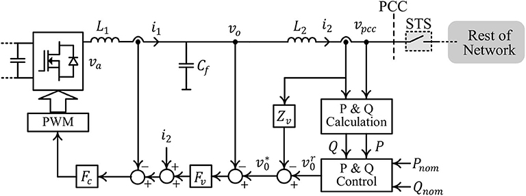
Figure 1. Typical control structure for a GFM converter based on droop control.
The converter can be connected/disconnected to/from the rest of the electrical network by closing/opening the static transfer switch (STS). A hierarchical control structure is used; at the top level, a droop control loop is used, which generates the reference for the output voltage control loop based on the real and reactive power outputs Po and Qo, respectively:
Here, , ω*, and θ* denote the L-N RMS magnitude, frequency, and phase reference for the converter output voltage vo. The virtual impedance Zv(s) is discussed in section 5. Throughout the rest of the paper, is assumed. The inner voltage and current control loops can be implemented in a stationary or synchronous reference frame, and the instantaneous voltage reference can be generated accordingly using , ω*, and θ*. Proportional-integral (PI) or proportional-resonant (PR) compensators are used as the voltage compensator Fv(s) and the current compensator Fc(s) for synchronous reference-frame and stationary reference-frame control implementation, respectively. Note that for the controller implementation, two sets of voltage sensors (vo and vpcc) and two sets of current sensors (i1 and i2) are required. In most applications, explicit passive or active damping measures are required to stabilize the voltage and current control loops (Awal et al., 2019a,b). Distinct time-scale separation is required among the different control loops. The innermost current control loop has the fastest dynamic response; the voltage control loop is designed to have a response at least an order of magnitude slower, and the droop control loop is designed with the slowest control bandwidth on the order of few Hz. To enable grid-connection while serving a local load, an additional set of voltage sensors is required to achieve pre-synchronization prior to closing the STS.
Figure 2 shows an oscillator-based control structure of a GFM converter. Unlike the droop-based GFM control structure, oscillator-based control does not require inner voltage and current control loops, effectively reducing the sensor requirements. As shown in Figure 2, one set of current sensor (i1) is required for updating the oscillator states. The virtual impedance Zv(s) is discussed in section 5 and is ignored throughout the rest of the analysis. We consider dispatchable virtual oscillator control, reported by Colombino et al. (2019), Colombino et al. (2017), and Seo et al. (2019), implemented as
Here, η, α, and κ are design parameters, and K and R(κ) are defined:
It is worth noting that the oscillator is implemented using the α and β axis components of the converter output current using magnitude-invariant Clarke transformation and denotes the line-to-neutral RMS voltage magnitude. Ignoring the parasitic elements and losses in the power devices, the output of the switch network can be approximated to be the same as the oscillator output, i.e., Va = V.
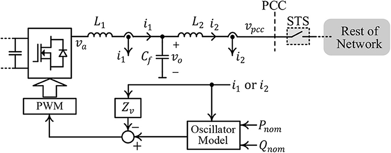
Figure 2. GFM converter control structure using oscillator-based control without inner voltage and current control loops.
The oscillator-based GFM converter can serve a local load and can be connected to the rest of the electrical network by closing the STS; however, additional voltage sensor may be required to achieve voltage and phase matching across the STS prior to closing. In the following section, a comparison between converter responses to voltage and frequency deviation at the PCC for droop control and oscillator-based control is presented.
3. Steady-State Terminal Response
Oscillator-based controllers have been shown to exhibit droop characteristics embedded implicitly in their non-linear dynamics (Johnson et al., 2016; Seo et al., 2019). The dynamic response of oscillator-based control differs from that of conventional droop-based methods. Similarly, their steady-state responses differ significantly. Two key factors contribute to the differences in steady-state behavior. First, in droop-based methods, inner voltage and current control loops are used and the desired droop response is implemented at the converter output terminal, whereas oscillator-based control is actuated at the switch terminals and the LC or LCL filter of the converter effectively becomes a part of the electrical network. Second, non-linear coupling exists between the real and reactive power droop loops. To illustrate the differences, we consider the GFM converter shown in Figure 3. The electrical network is modeled by a voltage source vg and an equivalent inductance Lg. Next, we compare the terminal characteristic for droop control and oscillator-based control at the PCC in response to variation in voltage magnitude and frequency of the source vg.
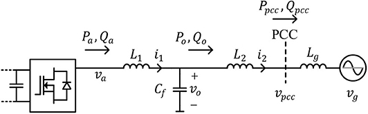
Figure 3. A GFM converter connected to an electrical network modeled by an equivalent source vg and an inductance Lg.
The converter parameters are listed in Table 1. The droop coefficients and oscillator parameters are designed to limit the real and reactive power outputs at the PCC within [−Prated, Prated] and [−Qrated, Qrated] when the frequency and voltage varies within Δω = (ωnom−ω) ∈ [−Δωmax, Δωmax] and ΔV = (Vnom − V) ∈ [−ΔVmax, ΔVmax]. The droop coefficients for droop control are selected:
The oscillator parameters in (3) are selected:
For droop control, the steady-state terminal response to variation in the voltage magnitude and frequency of vg is derived by power-flow solution of the network impedance ZN = sLN and the droop equations given by (1) and (2). For oscillator-based control, the steady-state droop response at the oscillator terminal among Va, ω, Pa, and Qa are given:
The terminal behavior of the oscillator is obtained through power flow solution of the LCL filter, including ZN and the droop response given by (7) and (8). First, we demonstrate that the selection of the droop control parameters and oscillator parameters limit the real and reactive power outputs within the rated values over the entire range of allowable operating conditions. Figures 4A,B show the real power vs. frequency droop response for droop control and oscillator-based control, respectively. It is worth noting that for droop control, the terminal response is shown between Po and Δω, whereas for oscillator control, the Pa vs. Δω response is shown. The responses are shown for three different grid voltage magnitude. For all three cases, identical droop response is obtained for droop control, however, for oscillator control the droop response shows noticeable variation for different grid voltage magnitude. Such dependence of the real power vs. frequency droop response on the voltage is evident from the droop equation for oscillator control given by (7). Contrastingly, the reactive power vs. voltage droop response given by (8) is independent of frequency, which is evident in Figure 5B. However, for droop control, a linear droop behavior is observed between Qo and ΔVo (see Figure 5A), whereas Qa vs. ΔVa droop response becomes non-linear when the VSC moves away from the nominal operating condition defined by (Qa, ΔVa) ≡ (0, 0). Overall, over the entire operating range, given by Δωg ∈ [−Δωmax, Δωmax] and ΔVx ∈ [−ΔVmax, ΔVmax], x ∈ a, o, the real and reactive power outputs of the VSC remain limited within the rated values for both droop control and oscillator control.
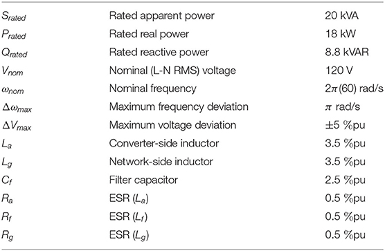
Table 1. Voltage source converter ratings.
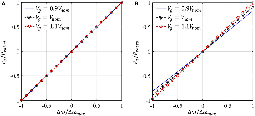
Figure 4. Real power vs. frequency Δω(= ωnom−ωg) droop response—(A) Po vs. Δω for droop control, (B) Pa vs. Δω for oscillator control.
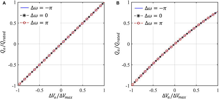
Figure 5. Reactive power vs. voltage ΔV(= Vnom − V) droop response—(A) Qo vs. ΔVo for droop control, (B) Qa vs. ΔVa for oscillator control.
Next, we investigate the terminal voltage at different grid condition for the two control methods. Figures 6A,B show the different node voltages for Δω = −π and Δω = π, respectively. At the point of actuation, oscillator control leads to smaller voltage deviation |ΔVa| from the nominal value than the voltage deviation |ΔVo| for droop control over the entire range of grid voltage for both cases. However, due to higher impedance Zosc ≈ (Za+Zg+ZN) between the point of actuation and vg for oscillator control than the impedance ZDC = (Zg + ZN) for droop control, larger voltage deviation is observed at the PCC for oscillator control than that for droop control.
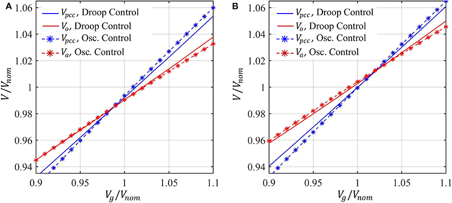
Figure 6. Different node voltages for variation in magnitude of vg when (A) Δω = −π, (B) Δω = π.
An overall comparison in the real and reactive power outputs at different grid condition for the two control methods is shown in Figure 7. The real power vs. frequency response for droop control remains independent of the voltage magnitude, whereas the droop behavior shows significant coupling with the voltage magnitude for oscillator control. Moreover, the reactive power vs. voltage droop response for oscillator control exhibits a non-linear behavior as expected.
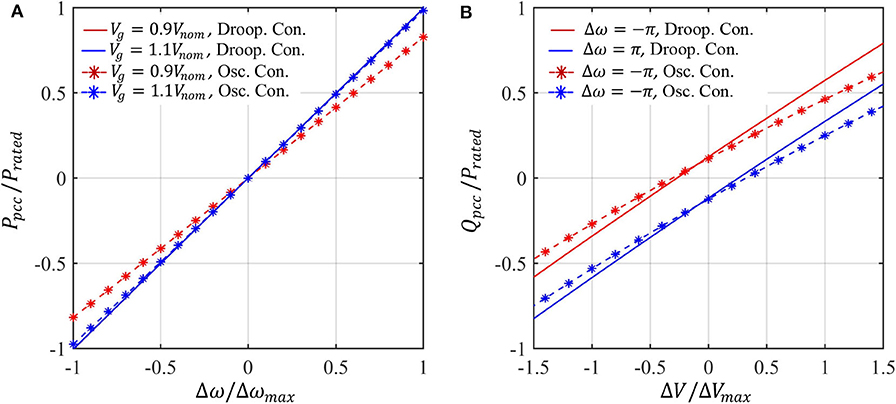
Figure 7. Comparison of terminal behavior at the PCC: (A) real power vs. frequency, (B) reactive power vs. voltage.
4. Transient Stability
The transient stability of both VOC and dVOC based islanded microgrid has been studied extensively in prior art (Johnson et al., 2016; Colombino et al., 2019). Compared to droop control, which is only well-defined in the near-synchronous speed, a coupled weakly non-linear limit-cycle oscillators network can achieve global asymptotic synchronization. In this paper, we focus on the transient stability of GFM control in grid-connected mode when subjected to large transient disturbances such as transmission line faults and severe grid voltage sags. Transient stability is defined as the ability of the GFM converter to maintain synchronism with the utility grid when subjected to a major grid disturbance (Kundur et al., 1994).
Figure 8 shows a typical system configuration for power system transient stability study. The converter is connected with an infinite bus through two transmission lines with reactances of Xg1 and Xg2, respectively. All the line impedances between the converter and transmission line are modeled as reactance Xl. The converter terminal voltage is defined as v (for droop control, it is the filter capacitor voltage; for dVOC, it is the oscillator voltage). The total reactance between the inverter and the infinite bus is defined as XT. The transient disturbance is considered as the sudden out of service (O/S) of the second transmission line, i.e., a sudden increase in XT.
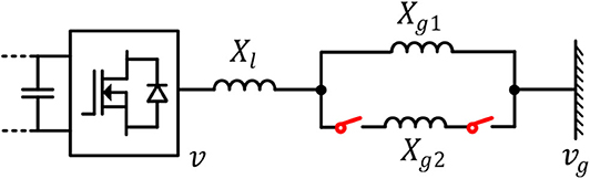
Figure 8. A grid-connected GFM converter system.
Next, we derive the power angle dynamic equations (swing equations) of both droop control and dVOC. In practical applications, droop control usually requires low-pass filters (LPFs) to suppress the power fluctuations. By incorporating the LPF, the P − ω droop relationship is given as
The power from the inverter to the infinite bus is given by
where Pmax denotes the power transfer capability of the system. The inverter power angle is defined as δ = θ − θg, where θ and θg are the phase angles of the inverter and infinite bus, respectively. The infinite bus is assumed to be operating at ωnom, therefore, . Based on (9) and (10), the power angle dynamic equation for droop control is obtained as
which is a second-order non-linear equation that is similar to the swing equation of a conventional synchronous machine. This is not surprising since droop control is inspired by the quasi-steady-state operation of synchronous machine. It should be noted that when the reactive power control loop is enabled, the coupling effect between the active and reactive power loop will deteriorate the transient stability of the converter (Pan et al., 2019). In practical applications, the converter is suggested to be operated in alternating-voltage control (AVC) mode under weak grid conditions to give the system best possible voltage support, which keeps the inverter terminal voltage constant while the reactive power is not explicitly controlled (Zhang et al., 2010; Wu and Wang, 2019). In this section, we therefore assume that the GFMC with droop control is working in the AVC mode, and the converter terminal voltage V is thus constant.
For dVOC, the dynamic equation in (3) can be transformed into polar coordinates:
Here, . By substituting into (12), we obtain the power angle dynamic equation of dVOC:
which is a first-order non-linear dynamic equation, and it is fundamentally different from the second-order swing equation of droop control. Owing to its limit cycle nature, the terminal voltage of a oscillator-based converter can be designed to be limited within a very narrow range. Therefore, the terminal voltage of dVOC can be considered as quasi-constant and the coupling effect between the active and reactive power can be neglected. In this paper, we only present a conceptual introduction of the basics of transient stability of grid-connected converters. Therefore, we will only consider the active power control part and show how droop control and dVOC are fundamentally different. A detailed and thorough comparative transient stability assessment of droop control and dVOC can be found in Yu et al. (2020).
The transient stability of droop control can be assessed using (11). As shown in (11), a droop-controlled converter has a similar second-order swing equation to that of synchronous machines (Kundur et al., 1994). Hence, its transient stability can be assessed via the equal area criterion (EAC) using the Po − δ curve (Alipoor et al., 2015; Xiong et al., 2016; Taul et al., 2019; Wu and Wang, 2020). EAC is the most widely used method for power system transient stability analysis, and its major benefit is that it is straightforward and easy to understand. As shown in Figure 9, the system operating point originally is stabilized at an equilibrium point a with a power angle of δe. When the second transmission line is O/S, Pmax will decrease and the Po − δ curve becomes the solid one. Due to inertia, the power angle cannot change instantly, and the operating point will be changed to b. Since now Pnom is greater than Po, the converter frequency (we can imagine the frequency as the angular speed of a virtual rotor in the converter) will accelerate and power angle will also increase. When it reaches point c, which is a new equilibrium point, the power angle will not stop at δne since the frequency of the converter is now higher than the infinite bus. After c, the converter frequency will decelerate but the power angle will keep increasing. The furthest possible decelerating point is d. EAC requires that if the maximum possible decelerating area A2 is larger than the accelerating area A1, then the synchronism can be maintained, and the system will finally be stabilized at c. One important transient stability feature of droop control is that the system is not necessarily stable even if a new equilibrium point exists.
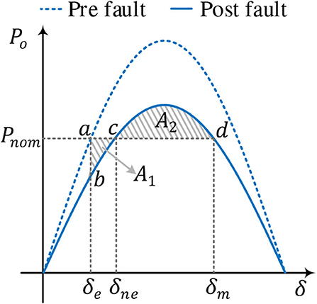
Figure 9. Transient stability analysis of droop control using the equal area criterion.
Although straightforward and simple, EAC neglects the damping term in droop control and can lead to very conservative assessment (Taul et al., 2019). A more precise transient stability assessment can be performed using phase portraits ( curve) (Strogatz, 2000; Pan et al., 2019; Taul et al., 2019), which is a commonly used graphical method for non-linear systems. As shown Figure 10A, the system originally operates at point a with an initial power angle of δe. When the fault occurs, owing to inertia, frequency and power angle cannot change instantly, i.e., both and δ remain unchanged at the instant. After disturbance, the power angle can evolve in different ways for different droop control parameter values (ωc, mp). In Figure 10A, two different cases are shown; we assume that in both cases the equilibrium point exists after disturbance, i.e., Pmax > Pnom. In the case of the dotted black line, δ first increases to point b on the axis, which is an open circle representing an unstable fixed point. Since point b is unstable, the system trajectory moves away until it reaches a stable fixed point c, which is marked by a solid black dot. There are a number of unstable fixed points along the trajectory that are not marked in the figure for simplicity. The system is stabilized at c. The power angle δm is the maximum power angle the system can reach during this transient (peak of the overshoot). And before the system finally reaches δne, back and forth oscillations exist in the power angle response. As can be seen in Figure 10A, if the δm crosses over a critical point δc, no fixed point exists and δ keeps increasing to infinity, leading to loss of synchronism. The critical angle δc can be easily identified using numerical methods.
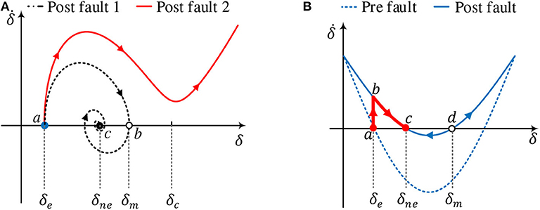
Figure 10. Transient stability analysis using phase portraits: (A) droop control, (B) dVOC.
For dVOC, we can also use phase portrait to assess its transient stability. As shown in Figure 10B, the system is at point a before the fault, which is a stable equilibrium point. At the fault instant, since Pmax decreases, the new curve becomes the solid one. The system operating point will move to point b. As can be seen from Figure 10B, the new curve has two equilibrium points c and d. c is a stable equilibrium point since c attracts the flow from any nearby point on either side. d is an unstable equilibrium point since it repels the flow on both sides. Therefore, when the system is on b at the fault instant, it will move to c monotonically and be stabilized at c without any overshoot and oscillation. This is advantageous over droop control that the system will always be stable if there is a new equilibrium point.
5. Harmonic Compensation
For droop-based conventional GFM control, the inner current and voltage loops facilitate supplementary control objective such as harmonic compensation in output current or in network voltage at specific nodes. In the following subsections, harmonic current and voltage suppression strategies for oscillator control are discussed.
5.1. Harmonic Current Rejection
Harmonic distortion in the converter output current may be caused by background harmonics in the PCC voltage vpcc such as odd harmonic distortion caused by non-linear loads in the grid/network. Dead time/blanking time, used for safe operation of power semiconductor devices, may also lead to odd harmonic distortions in the converter output current.
5.1.1. Harmonic Current Suppression in Droop-Based GFMCs
In droop-based converters, suppression of such harmonic currents is typically achieved through virtual impedance emulation. In essence, the converter output impedance is increased to very high values at the harmonic frequencies. Virtual impedance emulation in a droop-based VSC is shown in Figure 1. For impedance emulation, the reference for the output voltage control loop is modified as follows:
where denotes the original voltage reference generated from the droop equations for real and reactive power regulation and the virtual impedance Zv is designed as
Here, Z1(s) is the desired virtual impedance at the fundamental frequency ω1 and Kh denotes the virtual impedance magnitude at harmonic the harmonic frequency ωh = hω1; ωB,h denotes the bandwidth of the resonant response. The voltage controller and the current controller can be chosen as
The harmonic current rejection capability of the VSC can be quantified by the converter output impedance Zo,dc(s) = vo/(−i2(s)). The output impedance of the droop-based VSC, shown in Figure 1, can be derived as
Here, corresponds to the PWM and the sampling by the digital controller and one-sample (Ts) delay is considered due to controller implementation. The corresponding frequency response of the converter output impedance is shown in Figure 13 using controller parameters as Kpc = 1.5, Kpv = 0.05, Kiv = 10, Krv,1 = 100, ωB,h = 0.5, K3 = K5 = K7 = 200, K9 = 150, K11 = 200.
5.1.2. Harmonic Current Suppression in Oscillator-Based GFMCs
Virtual impedance emulation can be used in oscillator-based GFM converters. In Awal et al. (2020a), inductive, capacitive, and resistive virtual impedances are compared harmonic suppression and inductive impedance emulation for grid-side current feedback based controller implementation is recommended. For specific applications, however, grid-side current feedback may not be available, which is typical in most applications. In this work, we compare various types of virtual impedances for both converter-side and grid-side current feedback-based controller implementation. Figure 2 shows harmonic current suppression using either converter-side or grid-side current feedback. For the implementation of either one, the virtual resistance can be chosen as
The virtual resistance Rvir with a bandwidth ωb can be used for small-signal stabilization in case of a dominantly inductive grid. The resonant impedance Zh(s) can be chosen to provide inductive, capacitive, or resistive response at the harmonic frequencies:
The resonant impedances Zh,L, Zh,C, and Zh,R have phase responses of π/2, −π/2, and 0 with identical magnitude response of Kh.
First, we consider converter-side current feedback-based controller implementation. In the frequency range of interest (from hundreds of Hz to the Nyquist frequency), the oscillator dynamics can be ignored. The corresponding converter output impedance is determined as
Figures 11A,B compare the converter output impedances Zo(s) for different choices of Zh(s) when the band-limited virtual resistance is set as Rvir = 0 and Rvir = 0.3 Ω, respectively; the response is zoomed-in around the 7th harmonic for ease of explanation. It is interesting to note that without Rvir (see Figure 11A), all choices exhibit large phase jumps, which significantly reduce the stability margins of the system and may even lead to instability in extreme cases. Additionally, Zh = Zh,R causes a large decrease in impedance magnitude, which lowers disturbance rejection capability and renders the VSC susceptible to inter-harmonic distortions. Contrarily, Rvir = 0.3Ω reduces both the phase jump and dip in impedance magnitude for Zh = Zh,R, whereas Zh = Zh,L and Zh = Zh,C remain unaffected. Overall, resistive resonant impedance Zh,R along with the band-limited virtual resistance Rvir provides the best solution for converter-side current feedback based controller implementation.
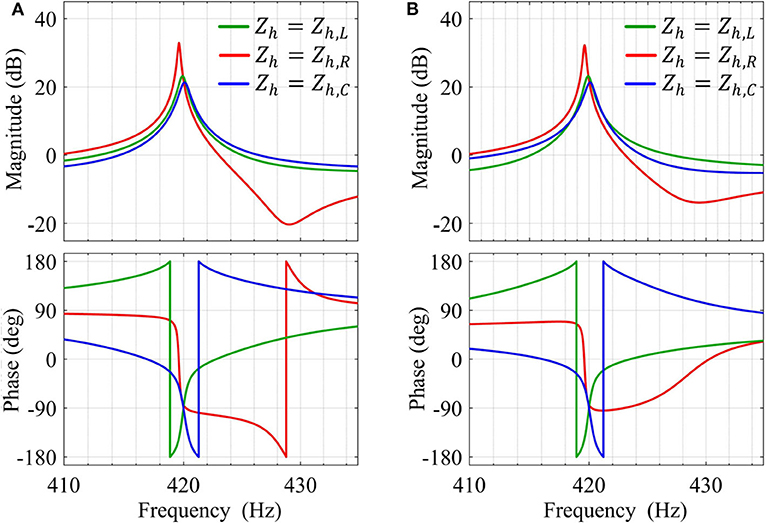
Figure 11. Converter output impedance (zoomed in around harmonic order h = 7) of an oscillator-based VSC emulating different types of resonant virtual impedance Zh(s) using converter-side current feedback, when—(A) Rvir = 0 and (B) Rvir = 0.3 Ω.
Next, controller implementation using grid-side current feedback is discussed. The converter output impedance is given:
Comparison among converter output impedances with different choices for Zh while setting Rvir = 0 and Rvir = 0.3Ω are shown in Figures 12A,B, respectively. Capacitive resonant impedance, i.e., Zh = Zh,C, gives large phase jumps in both cases, whereas inductive impedance emulation by setting Zh = Zh,L gives small phase-jump in both cases without causing inter-harmonic susceptibility by lowering impedance magnitude; Similar to converter-side feedback based implementation, Zh = Zh,R gives small phase jump with Rvir ≠ 0 but impedance magnitude falls immediately above the harmonic frequency. In (Awal et al., 2020a), passivity of converter impedance is used as a sufficient condition for stability while the grid-impedance is not known. The converter impedance is considered passive when −π/2 < ∠Zo(jω) < π/2. It is worth noting that Zh,L introduces a small non-passive region close to the harmonic frequency without any dip in the impedance magnitude, whereas Zh,R does not cause non-passive behavior but causes a fall in the impedance magnitude very close to the harmonic frequency. The choice between the two options is at the discretion of the designer; potential inter-harmonic distortion and uncertainty in grid/network impedance should be considered while selecting between the two.
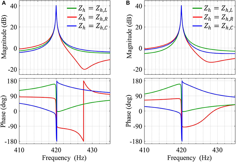
Figure 12. Converter output impedance (zoomed in around harmonic order h = 7) of an oscillator-based VSC emulating different types of resonant virtual impedance Zh(s) using grid-side current feedback, when (A) Rvir = 0 and (B) Rvir = 0.3 Ω.
Figure 13 shows comparison among converter output impedances of a droop-based GFMC and oscillator-based GFMCs using converter-side and grid side current feedback, where Zh = Zh,R and Zh = Zh,L is used for the two cases, respectively, and Rvir = 0.3 is used for both. Evidently, the droop-based GFMC exhibits large phase jumps around the harmonic frequencies and well as in the high frequency range whereas oscillator-based GFMCs incur smaller non-passive regions around the harmonic frequencies and no non-passive response is introduced in the high-frequency range. From Figures 1, 2, it is evident that oscillator-based GFMCs enable significantly simpler controller implementation to achieve harmonic current suppression capability without introducing large non-passive regions.
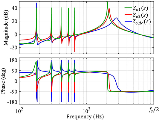
Figure 13. Converter output impedance Zo(s) with K3 = 100 Ω, K3 = 100 Ω, K5 = 100 Ω, K7 = 100 Ω, K9 = 90 Ω, K11 = 90 Ω, ωB,3 = ωB,5 = ωB,7 = ωB,9 = ωB,11 = 0.5 rad/s, Rvir = 0.3 Ω, and ωb = 12000π rad/s: Zo1(s) using (20) with converter-side current feedback and Zo2(s) using (21) with grid-side current feedback.
Virtual impedance emulation enables us to selectively increase the converter output impedance at the harmonic frequencies, which effectively suppresses harmonic currents contributed by harmonic voltage distortions on either the grid side or the converter side. Explicit harmonic detection/extraction is not required, and the converter filter parameters are used only to assess the stability margins of the systems; exact knowledge of the passive filter components are not necessary. The compensation filters are implemented in the digital controller unlike the hardware filter proposed in Duong et al. (2018b).
The effectiveness of the harmonic current suppression is demonstrated in Figure 14. For a grid-tied operation using oscillator control, presence of harmonic distortion in the grid voltage leads to severe harmonic distortion in the converter output current (see Figure 14A). With converter-side current feedback, using (18) and Zh = Zh,R harmonic suppression is achieved, as shown in Figure 14B.
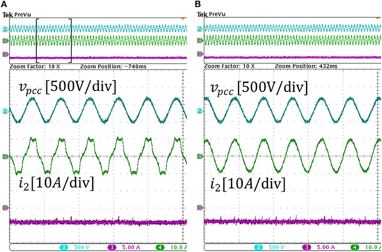
Figure 14. Converter output current: (A) without harmonic suppression, (B) with harmonic current suppression using converter-side current feedback.
5.2. Harmonic Voltage Compensation
With the increasing application of non-linear loads, such as computers and many other home appliances drawing harmonics currents from the grid, power quality issues are becoming a serious concern in AC distribution systems. The harmonic currents demand may result in severe voltage distortion at the PCC and affect sensitive loads or even interfere with the communication systems of microgrids. Using GFMCs for PCC harmonic voltage compensation as an ancillary service to the grid is seen as a cost-competitive and effective method (Li and He, 2014). In this section, the state-of-the-art droop-based methods will be briefly reviewed, and the oscillator-based scheme will be detailed and compared with the droop-based methods.
5.2.1. Harmonic Voltage Suppression in Droop-Based GFMCs
In the droop controlled GFMCs, an inner dual loop control structure is mostly used for voltage tracking. While a proportional-resonant (PR) controller that resonates at the fundamental frequency is usually enough for normal operations, a more effective and complicated controller is required when non-linear load is a serious concern. When the load current is severely polluted with low order harmonic components, advanced voltage control structures, such as multiple PR controllers, are usually implemented to ensure good voltage tracking and harmonics rejection (Wang et al., 2012, 2013; He et al., 2014; Liu et al., 2019). Another popular alternative is repetitive controller (Qi et al., 2019). These advanced controllers greatly complicate the control system design and adds substantial computational burden to the digital processors. Another challenge for the multiple PRs or repetitive controller lies in the fact that for a practical AC distribution system, especially for an islanded AC microgrid, the system frequency is not always fixed at its nominal value but will change in real time according to the loading level of the system. This further complicates the controller design since a changing fundamental frequency will make these controllers less effective if they are not improved with frequency adaptive features.
In addition to advanced voltage controllers, the droop control structure should be improved in order to suppress the voltage harmonics at PCC. One option is to modify the droop control with addition of harmonic droop controllers (Zhong, 2012). The most widely used method is virtual impedance emulation at harmonic frequencies. Some of the existing virtual impedance emulation schemes for droop control can basically be applied in a oscillator-based GMFC with slight modification. We will introduce the virtual impedance scheme in detail in the next section.
5.2.2. Harmonic Voltage Suppression in Oscillator-Based GFMCs
In this section, we will show that with oscillator-based scheme, the complicated voltage control structures can be avoided. A limit cycle oscillator can strongly damp the harmonics from the input, which helps a VOC based inverter maintain highly sinusoidal terminal voltage even if the load current is polluted with substantial harmonic components (Awal et al., 2020a). However, the PCC voltage can still be distorted with harmonics when feeding non-linear loads. Next, we analyze the mechanism for the voltage distortion at PCC. An islanded GFM converter with VOC and the corresponding impedance model for this scenario are depicted in Figure 15A,B, where the total network impedance ZN has an inductance of LN = L1 + Ll and resistance of RN = Rl, respectively; Zvir is the virtual impedance that will be introduced later. It can be seen in Figure 15A that with oscillator-based control, the control structure can be greatly simplified. It will be demonstrated later in this section that the simple oscillator model alone can achieve the functionalities of both advanced voltage controllers and droop control combined.
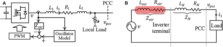
Figure 15. System of an islanded GFM converter: (A) system diagram, (B) voltage harmonics analysis.
Since the load is non-linear, the load current i can be decomposed as the fundamental component ih1 and the k-th order harmonic component ihk. Without any harmonic voltage compensation, the voltage at the PCC vpcc is given as
which shows that vpcc will be distorted due to the harmonics in i1 and the impedance even if the oscillator voltage is sinusoidal.
To suppress the harmonic distortion in vpcc, one feasible solution is to design the virtual impedance Zvir such that the total impedance at each harmonic frequency ωk is 0, i.e.,
where ωk = kω1, and ω1 is the fundamental frequency. It should be noted that ω1 is a load- and system-dependent variable and could deviate from ωnom due to the droop characteristic of VOC in islanded mode. As long as (23) is satisfied, the harmonic currents will not cause any harmonic voltage drop across the network, and vpcc will ideally be sinusoidal. To that end, Rvk and Lvk can be designed to cancel the total network resistance RN and LN at ωk, respectively. The overall virtual impedance realization diagram is given in Figure 16, in which ihk and qihk are the k-th harmonic current and its quadrature component. It should be noted that ωk is not a fixed value but rather an adaptive value obtained by the current harmonics extraction block, which makes the control scheme frequency adaptive. In this work, up to 13th harmonic currents are extracted and used to implement virtual impedance. The voltage vvir induced by virtual impedance is given as
The current harmonics extraction block can be realized using a combination of multiple second-order generalized integrators (MSOGI) and a frequency-locked loop (FLL), i.e., MSOGI-FLL (Rodriguez et al., 2011; Golestan et al., 2019). The harmonic decoupling network (HDN) should be adopted to isolate different harmonics in the input signal and enhance the selective filtering capability, which is frequency adaptive thanks to the use of FLL. Different from droop control, in which the system frequency is determined by the droop relationship Wang et al., 2012, 2013, oscillator-based control does not have an explicit function to obtain the fundamental frequency. By using a frequency adaptive block FLL, MSOGI-FLL decomposes i into its fundamental component i1, harmonic components ihk, and the corresponding quadrature components qih1, qihk.
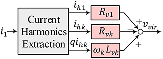
Figure 16. Virtual impedance scheme for voltage harmonics mitigation.
To study the effectiveness of the virtual impedance scheme, a small-signal model of the oscillator-based GMFC can be derived as shown in Figure 17, where Zosc(s) denotes the small-signal impedance of the VOC. The harmonic current has limited influence on the output voltage of the oscillator due to its limit cycle nature, which suggests that the impedance introduced by VOC at harmonic frequencies is close to 0. Since this paper deals with voltage harmonics at the 3rd, 5th, 7th… order, the influence of VOC on the overall impedance at these harmonic frequencies can be neglected, i.e., Zosc(jωk) ≈ 0.

Figure 17. Impedance model of VOC with virtual impedance control.
MSOGI-FLL can be linearized using the methods proposed in Rodriguez et al. (2011). Firstly, we consider the modeling of the basic SOGI-FLL. In this work, the dynamic change of the system frequency is not considered and thus the dynamics of the FLL can be neglected. We assume that the SOGI-FLL is operating at a steady-state frequency ω1, and the transfer functions from i to ih1 and from i to qih1 can be modeled respectively:
where ksogi is the SOGI gain. These two transfer functions are also applicable to other SOGI blocks in MSOGI-FLL by substituting the frequency ω1 and gain ksogi with ωk and ksogi/k, respectively. The transfer functions for the k-th block are denoted as Gαk(s) and Gβk(s).
Next, we consider the effect of HDN. The k-th component of the current can be obtained as
Then the transfer functions from the input i to the k-th harmonic components by taking HDN into account can be obtained as Rodriguez et al. (2011):
The virtual impedance can be derived as
In Figure 17, Td(s) represents the delay introduced by digital control and PWM. Based on Figure 17, the total impedance can be easily derived:
To highlight the virtual impedance influence, the total impedance without virtual impedance is marked as Ztotori(s). The Bode plots of the impedances are given in Figure 18. In Figure 18, it can be seen that with the proposed virtual impedance scheme, the total impedance is considerably small at critical frequencies, such as ω3, ω5, ω7, etc., which ensures that the harmonic load current will not cause considerable harmonic voltage drop across the inverter filter and feeder. Therefore, the voltage distortion at PCC can be effectively suppressed. It should be noted that for the virtual impedance method to work effectively, the network impedance should be known. Therefore, the impedance information should be as accurate as possible. To further improve the performance, the virtual impedance can be made adaptive if an online impedance estimation is available to handle applications with a time-varying network impedance.
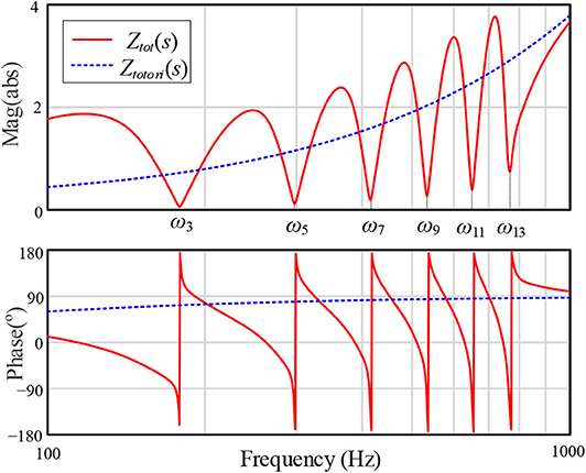
Figure 18. Bode plots of Ztot(s) and Ztotori(s) with Vnom = 200V, ωnom = 120π rad/s, L1 = 300μH, Ll = 300μH, Rl = 0.22Ω, Rv1 = 0.5Ω, Rvk = 0.22Ω, Lvk = 600μH, ksogi = 1.414.
The effectiveness of the harmonic voltage suppression is demonstrated in Figures 19A,B. With the original VOC, vpcc is severely distorted when the load current contains considerable harmonics components; when the proposed virtual impedance scheme is enabled, vpcc becomes highly sinusoidal.
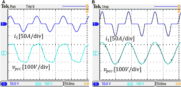
Figure 19. Load current and PCC voltage: (A) with the original VOC, (B) harmonic suppression using the proposed virtual impedance scheme.
6. Conclusion
The emerging oscillator-based methods for primary controls of power electronic converters, which sits on top of the local PWM control, address a number of challenges associated with droop-type controls since the latter are based on phasor approximation and not well-defined in the super-synchronous time scale. While both droop- and oscillator-based controls inherently function on droop relations, distinct differences exist between the two methods in steady state and transient response characteristics for both reference tracking and stability behavior. For oscillator-based methods, unlike droop control, the desired droop response is actuated at the output of the switch network instead of the converter terminal since the inner current and voltage control loops are not used for the former. Droop controls are independent of the voltage magnitude at the point of common coupling, while the droop behavior shows significant coupling with the oscillator node for oscillator-based methods. The transient stability of oscillator-based control under fault conditions differ significantly from that of droop-based methods with the former having the advantage of a guaranteed stability if a new equilibrium point exists. Droop-based methods easily facilitate achieving harmonic current suppression due to the distinct time-scale separation of control loops, while in oscillator-based method explicit controls have to be developed. Harmonic current rejection using either converter-side or grid-side currents with an oscillator-based method is presented in this paper with simulation and experimental results; it has also been demonstrated that oscillator-based methods can easily employ harmonic voltage compensation when feeding non-linear loads. A major advantage of oscillator-based method is the ease of implementation with fewer sensor requirement compared to droop-based methods. While oscillator-based controllers are more recent compared to the mature technology of droop controls, we expect to see more evolving novel approaches especially for the former.
Data Availability Statement
The raw data supporting the conclusions of this article will be made available by the authors, without undue reservation.
Author Contributions
MA, HY, SL, and IH: substantial contributions to the conception or design of the work, or the acquisition, analysis or interpretation of data for the work, drafting the work or revising it critically for important intellectual content, providing approval for publication of the content, and agree to be accountable for all aspects of the work in ensuring that questions related to the accuracy or integrity of any part of the work are appropriately investigated and resolved. All authors contributed to the article and approved the submitted version.
Conflict of Interest
The authors declare that the research was conducted in the absence of any commercial or financial relationships that could be construed as a potential conflict of interest.
References
Alipoor, J., Miura, Y., and Ise, T. (2015). Power system stabilization using virtual synchronous generator with alternating moment of inertia. IEEE J. Emerg. Select. Top. Power Electron. 3, 451–458. doi: 10.1109/JESTPE.2014.2362530
Awal, M. A., Yu, H., Flora, L. D., Yu, W., Lukic, S., and Husain, I. (2019a). “Observer based admittance shaping for resonance damping in voltage source converters with LCL filter,” in 2019 IEEE Energy Conversion Congress and Exposition (ECCE), (Baltimore, MD) 4455-4462. doi: 10.1109/ECCE.2019.8913194
Awal, M. A., Yu, H., Husain, I., Yu, W., and Lukic, S. (2020a). Selective harmonic current rejection for virtual oscillator controlled grid-forming voltage source converters. IEEE Trans. Power Electron. 35, 8805–8818. doi: 10.1109/TPEL.2020.2965880
Awal, M. A., Yu, H., Tu, H., Lukic, S. M., and Husain, I. (2020b). Hierarchical control for virtual oscillator based grid-connected and islanded microgrids. IEEE Trans. Power Electron. 35, 988-1001. doi: 10.1109/TPEL.2019.2912152
Awal, M. A., Yu, W., and Husain, I. (2019b). Passivity based predictive-resonant current control for resonance damping in LCL-equipped VSCs. IEEE Trans. Indus. Appl. 56, 1702–1713. doi: 10.1109/TIA.2019.2959594
Beck, H.-P., and Hesse, R. (2007). “Virtual synchronous machine,” in 2007 9th International Conference on Electrical Power Quality and Utilisation (Barcelona: IEEE), 1-6. doi: 10.1109/EPQU.2007.4424220
Chen, Y., Hesse, R., Turschner, D., and Beck, H.-P. (2011). “Improving the grid power quality using virtual synchronous machines,” in 2011 International Conference on Power Engineering, Energy and Electrical Drives (Malaga: IEEE), 1-6. doi: 10.1109/PowerEng.2011.6036498
Colombino, M., Gross, D., Brouillon, J., and Dorfler, F. (2019). Global phase and magnitude synchronization of coupled oscillators with application to the control of grid-forming power inverters. IEEE Trans. Automat. Control. 64, 4496–4511. doi: 10.1109/TAC.2019.2898549
Colombino, M., Groß, D., and Dorfler, F. (2017). “Global phase and voltage synchronization for power inverters: a decentralized consensus-inspired approach,” in 2017 IEEE 56th Annual Conference on Decision and Control (CDC), 5690-5695. doi: 10.1109/CDC.2017.8264518
Cortes, P., Rodriguez, J., Antoniewicz, P., and Kazmierkowski, M. (2008). Direct power control of an AFE using predictive control. IEEE Trans. Power Electron. 23, 2516–2523. doi: 10.1109/TPEL.2008.2002065
Duong, M. Q., Le, K. H., Grimaccia, F., Leva, S., and Mussetta, M. (2018a). “Modeling and performance evaluation of a fuzzy logic controller for buck-boost DC/DC converters,” in 2018 IEEE International Conference on Fuzzy Systems (FUZZ-IEEE) (Rio de Janeiro: IEEE), 1-7. doi: 10.1109/FUZZ-IEEE.2018.8491527
Duong, M. Q., Nguyen, V. T., Tran, A. T., Sava, G. N., and Le, T. M. C. (2018b). “Performance assessment of low-pass filters for standalone solar power system,” in 2018 International Conference and Exposition on Electrical And Power Engineering (EPE) (Iasi), 503-507. doi: 10.1109/ICEPE.2018.8559942
Golestan, S., Guerrero, J. M., Musavi, F., and Vasquez, J. (2019). Single-phase frequency-locked loops: a comprehensive review. IEEE Trans. Power Electron. 34, 11791–11812. doi: 10.1109/TPEL.2019.2910247
Guerrero, J. M., Chandorkar, M., Lee, T.-L., and Loh, P. C. (2013). Advanced control architectures for intelligent microgrids-Part I: decentralized and hierarchical control. IEEE Trans. Indus. Electron. 60, 1254–1262. doi: 10.1109/TIE.2012.2194969
Guerrero, J. M., Vasquez, J. C., Matas, J., de Vicuna, L. G., and Castilla, M. (2011). Hierarchical control of droop-controlled AC and DC microgrids-A general approach toward standardization. IEEE Trans. Indus. Electron. 58, 158–172. doi: 10.1109/TIE.2010.2066534
Gui, Y., Kim, C., Chung, C. C., Guerrero, J. M., Guan, Y., and Vasquez, J. C. (2018). Improved direct power control for grid-connected voltage source converters. IEEE Trans. Indus. Electron. 65, 8041–8051. doi: 10.1109/TIE.2018.2801835
Han, H., Hou, X., Yang, J., Wu, J., Su, M., and Guerrero, J. M. (2016). Review of power sharing control strategies for islanding operation of AC microgrids. IEEE Trans. Smart Grid 7, 200–215. doi: 10.1109/TSG.2015.2434849
Han, H., Liu, Y., Sun, Y., Su, M., and Guerrero, J. M. (2015). An improved droop control strategy for reactive power sharing in islanded microgrid. IEEE Trans. Power Electron. 30, 3133–3141. doi: 10.1109/TPEL.2014.2332181
Han, Y., Li, H., Shen, P., Coelho, E. A. A., and Guerrero, J. M. (2017a). Review of active and reactive power sharing strategies in hierarchical controlled microgrids. IEEE Trans. Power Electron. 32, 2427–2451. doi: 10.1109/TPEL.2016.2569597
Han, Y., Shen, P., Zhao, X., and Guerrero, J. M. (2017b). Control strategies for islanded microgrid using enhanced hierarchical control structure with multiple current-loop damping schemes. IEEE Trans. Smart Grid 8, 1139–1153. doi: 10.1109/TSG.2015.2477698
He, J., Li, Y. W., and Blaabjerg, F. (2014). An enhanced islanding microgrid reactive power, imbalance power, and harmonic power sharing scheme. IEEE Trans. Power Electron. 30, 3389–3401. doi: 10.1109/TPEL.2014.2332998
Johnson, B., Rodriguez, M., Sinha, M., and Dhople, S. (2017). “Comparison of virtual oscillator and droop control,” in 2017 IEEE 18th Workshop on Control and Modeling for Power Electronics (COMPEL) (Stanford, CA), 1-6. doi: 10.1109/COMPEL.2017.8013298
Johnson, B. B., Dhople, S. V., Hamadeh, A. O., and Krein, P. T. (2014). Synchronization of parallel single-phase inverters with virtual oscillator control. IEEE Trans. Power Electron. 29, 6124–6138. doi: 10.1109/TPEL.2013.2296292
Johnson, B. B., Sinha, M., Ainsworth, N. G., Dorfler, F., and Dhople, S. V. (2016). Synthesizing virtual oscillators to control islanded inverters. IEEE Trans. Power Electron. 31, 6002–6015. doi: 10.1109/TPEL.2015.2497217
Kim, J., Guerrero, J. M., Rodriguez, P., Teodorescu, R., and Nam, K. (2011). Mode adaptive droop control with virtual output impedances for an inverter-based flexible AC microgrid. IEEE Trans. Power Electron. 26, 689–701. doi: 10.1109/TPEL.2010.2091685
Kundur, P., Balu, N. J., and Lauby, M. G. (1994). Power System Stability and Control, Vol. 7. New York, NY: McGraw-Hill.
Li, Y. W., and He, J. (2014). Distribution system harmonic compensation methods: an overview of DG-interfacing inverters. IEEE Indus. Electron. Mag. 8, 18-31. doi: 10.1109/MIE.2013.2295421
Liu, B., Liu, Z., Liu, J., An, R., Zheng, H., and Shi, Y. (2019). An adaptive virtual impedance control scheme based on small-ac-signal injection for unbalanced and harmonic power sharing in islanded microgrids. IEEE Trans. Power Electron. 34, 12333–12355. doi: 10.1109/TPEL.2019.2905588
Liu, J., Miura, Y., and Ise, T. (2016). Comparison of dynamic characteristics between virtual synchronous generator and droop control in inverter-based distributed generators. IEEE Trans. Power Electron. 31, 3600–3611. doi: 10.1109/TPEL.2015.2465852
Lu, M., Dutta, S., Purba, V., Dhople, S., and Johnson, B. (2019). “A grid-compatible virtual oscillator controller: analysis and design,” in 2019 IEEE Energy Conversion Congress and Exposition (ECCE) (Baltimore, MD), 2643–2649. doi: 10.1109/ECCE.2019.8913128
Mohamed, Y. A.-R. I., and Radwan, A. A. (2011). Hierarchical control system for robust microgrid operation and seamless mode transfer in active distribution systems. IEEE Trans. Smart Grid 2, 352–362. doi: 10.1109/TSG.2011.2136362
Pan, D., Wang, X., Liu, F., and Shi, R. (2019). Transient stability of voltage-source converters with grid-forming control: a design-oriented study. IEEE J. Emerg. Select. Top. Power Electron. 8, 1019–1033. doi: 10.1109/JESTPE.2019.2946310
Qi, Y., Lin, P., Wang, Y., and Tang, Y. (2019). Two-dimensional impedance-shaping control with enhanced harmonic power sharing for inverter-based microgrids. IEEE Trans. Power Electron. 34, 11407–11418. doi: 10.1109/TPEL.2019.2898670
Rocabert, J., Luna, A., Blaabjerg, F., and Rodríguez, P. (2012). Control of power converters in AC microgrids. IEEE Trans. Power Electron. 27, 4734–4749. doi: 10.1109/TPEL.2012.2199334
Rodriguez, P., Luna, A., Candela, I., Mujal, R., Teodorescu, R., and Blaabjerg, F. (2011). Multiresonant frequency-locked loop for grid synchronization of power converters under distorted grid conditions. IEEE Trans. Indus. Electron. 58, 127–138. doi: 10.1109/TIE.2010.2042420
Seo, G., Colombino, M., Subotic, I., Johnson, B., Groß, D., and Dorfler, F. (2019). “Dispatchable virtual oscillator control for decentralized inverter-dominated power systems: analysis and experiments,” in 2019 IEEE Applied Power Electronics Conference and Exposition (APEC), 561-566. doi: 10.1109/APEC.2019.8722028
Shi, Z., Li, J., Nurdin, H. I., and Fletcher, J. E. (2019). Comparison of virtual oscillator and droop controlled islanded three-phase microgrids. IEEE Trans. Energy Convers. 34, 1769–1780. doi: 10.1109/TEC.2019.2922447
Sinha, M., Dorfler, F., Johnson, B. B., and Dhople, S. V. (2016). “Synchronization of Liénard-type oscillators in uniform electrical networks,” in 2016 American Control Conference (ACC) (Boston, MA: IEEE), 4311-4316. doi: 10.1109/ACC.2016.7525600
Sinha, M., Dorfler, F., Johnson, B. B., and Dhople, S. V. (2017). Uncovering droop control laws embedded within the nonlinear dynamics of Van der Pol oscillators. IEEE Trans. Control Netw. Syst. 4, 347–358. doi: 10.1109/TCNS.2015.2503558
Strogatz, S. H. (2000). Nonlinear Dynamics and Chaos: With Applications to Physics, Biology, Chemistry, and Engineering. Boulder, CO: Westview Press.
Sun, Y., Hou, X., Yang, J., Han, H., Su, M., and Guerrero, J. M. (2017). New perspectives on droop control in AC microgrid. IEEE Trans. Indus. Electron. 64, 5741–5745. doi: 10.1109/TIE.2017.2677328
Taul, M. G., Wang, X., Davari, P., and Blaabjerg, F. (2019). An overview of assessment methods for synchronization stability of grid-connected converters under severe symmetrical grid faults. IEEE Trans. Power Electron. 34, 9655–9670. doi: 10.1109/TPEL.2019.2892142
Vasquez, J., Guerrero, J., Luna, A., Rodriguez, P., and Teodorescu, R. (2009). Adaptive droop control applied to voltage-source inverters operating in grid-connected and islanded modes. IEEE Trans. Indus. Electron. 56, 4088–4096. doi: 10.1109/TIE.2009.2027921
Wang, X., Blaabjerg, F., and Chen, Z. (2012). Synthesis of variable harmonic impedance in inverter-interfaced distributed generation unit for harmonic damping throughout a distribution network. IEEE Trans. Indus. Appl. 48, 1407–1417. doi: 10.1109/TIA.2012.2199955
Wang, X., Blaabjerg, F., and Chen, Z. (2013). Autonomous control of inverter-interfaced distributed generation units for harmonic current filtering and resonance damping in an islanded microgrid. IEEE Trans. Indus. Appl. 50, 452–461. doi: 10.1109/TIA.2013.2268734
Wu, H., and Wang, X. (2019). Design-oriented transient stability analysis of grid-connected converters with power synchronization control. IEEE Trans. Indus. Electron. 66, 6473-6482. doi: 10.1109/TIE.2018.2875669
Wu, H., and Wang, X. (2020). A mode-adaptive power-angle control method for transient stability enhancement of virtual synchronous generators. IEEE J. Emerg. Select. Top. Power Electron. 8, 1034–1049. doi: 10.1109/JESTPE.2020.2976791
Xiong, L., Zhuo, F., Wang, F., Liu, X., Chen, Y., Zhu, M., et al. (2016). Static synchronous generator model: a new perspective to investigate dynamic characteristics and stability issues of grid-tied PWM inverter. IEEE Trans. Power Electron. 31, 6264–6280. doi: 10.1109/TPEL.2015.2498933
Yao, W., Chen, M., Matas, J., Guerrero, J. M., and Qian, Z.-M. (2011). Design and analysis of the droop control method for parallel inverters considering the impact of the complex impedance on the power sharing. IEEE Trans. Indus. Electron. 58, 576–588. doi: 10.1109/TIE.2010.2046001
Yu, H., Awal, M. A., Tu, H., Du, Y., Lukic, S., and Husain, I. (2019). “Passivity-oriented discrete-time voltage controller design for grid-forming inverters,” in 2019 IEEE Energy Conversion Congress and Exposition (ECCE) (Baltimore, MD), 469–475. doi: 10.1109/ECCE.2019.8912988
Yu, H., Awal, M. A., Tu, H., Husain, I., and Lukic, S. (2020). “Comparative transient stability assessment of droop and dispatchable virtual oscillator controlled grid-connected inverters,” in IEEE Transactions on Power Electronics (IEEE), 2119–2130. doi: 10.1109/TPEL.2020.3007628
Zhang, L., Harnefors, L., and Nee, H. (2010). Power-synchronization control of grid-connected voltage-source converters. IEEE Trans. Power Syst. 25, 809–820. doi: 10.1109/TPWRS.2009.2032231
Zhong, Q.-C. (2012). Harmonic droop controller to reduce the voltage harmonics of inverters. IEEE Trans. Indus. Electron. 60, 936–945. doi: 10.1109/TIE.2012.2189542
Zhong, Q.-C. (2017). Power-electronics-enabled autonomous power systems: architecture and technical routes. IEEE Trans. Indus. Electron. 64, 5907–5918. doi: 10.1109/TIE.2017.2677339
Zhong, Q.-C., and Weiss, G. (2011). Synchronverters: inverters that mimic synchronous generators. IEEE Trans. Indus. Electron. 58, 1259–1267. doi: 10.1109/TIE.2010.2048839
Zhong, Q.-C., and Zeng, Y. (2016). Universal droop control of inverters with different types of output impedance. IEEE Access 4, 702–712. doi: 10.1109/ACCESS.2016.2526616
Keywords: droop controls, oscillator controls, grid forming converters, harmonic compensation, transient stability, virtual oscillator control, VOC, dVOC
Citation: Awal MA, Yu H, Lukic S and Husain I (2020) Droop and Oscillator Based Grid-Forming Converter Controls: A Comparative Performance Analysis. Front. Energy Res. 8:168. doi: 10.3389/fenrg.2020.00168
Received: 06 February 2020; Accepted: 30 June 2020;
Published: 07 October 2020.
Edited by:
Mohd Hasan Ali, University of Memphis, United StatesReviewed by:
Minh Quan Duong, The University of Danang, VietnamLucian Toma, Politehnica University of Bucharest, Romania
Copyright © 2020 Awal, Yu, Lukic and Husain. This is an open-access article distributed under the terms of the Creative Commons Attribution License (CC BY). The use, distribution or reproduction in other forums is permitted, provided the original author(s) and the copyright owner(s) are credited and that the original publication in this journal is cited, in accordance with accepted academic practice. No use, distribution or reproduction is permitted which does not comply with these terms.
*Correspondence: Iqbal Husain, ihusain2@ncsu.edu