Hydraulic Optimization of Two-Way Counter-rotating Axial Flow Pump Turbine
 Wang Xiuli
 Lin Bin
 Li Yang1
  Zhu Rongsheng
 Long Yun
 Fu Qiang
- 1China National Research Center of Pumps, Jiangsu University, Zhenjiang, China
- 2Marine Design & Research Institute of China, Shanghai, China
The two-way counter-rotation technology is mainly applied to the tidal power station. In this paper, the hydrodynamic optimization of the two-way counter-rotating axial-flow pump turbine is carried out. Under the premise of realizing the forward and reverse power generation and the forward and negative pumping basic function, it has important engineering significance and academic value for improving the pump turbine performance of various working conditions. The main contents are as follows: hydraulic design of “S”-shaped blade for the two-way counter-rotating axial-flow pump turbine is conducted, and the influence of the gap between different impeller stages on the performance is calculated and analyzed, and the variation law of head and efficiency of the pump turbine under different inter-stage clearances is obtained. And the influence of the inter-stage gap on the unit is summarized from the vorticity distribution and the axial section pressure cloud diagram analysis, and the range of the best inter-stage gap of the unit performance is determined.
Introduction
At present, fossil fuels still account for the vast majority of global energy demand, and their mining progress and environmental degradation have far exceeded imagination. As a kind of renewable energy source (Liu et al., 2018; Xu and Wang, 2019; Gao et al., 2016; Kreitmair et al., 2019) tidal energy has the advantages of high efficiency, cleanliness, and large-scale development and application. Similar to ordinary hydropower generation, tidal power generation is that during high tide, seawater is stored in reservoirs as potential energy, and then the seawater is released during the ebb tide. Using the height difference between the high tide and the low tide level to drive the turbine to rotate, which in turn translates into generator power generation. According to the layout and structure of the turbine, the hydroelectric generating sets for tidal power generation have the following categories (Peng et al., 2017; Zhang, 2011; Lee et al., 2018; Yin and Wang, 2010): full-flow type, shaft-through flow type, vertical cross-flow type, bulb cross-flow type. The bulb cross-flow type’s pumping conditions and power generation conditions can obtain excellent performance due to the straightness of the inlet and outlet water channels. Applying it to the tidal power station can realize six functions of two-way power generation, two-way pumping and two-way water drain, and it is very suitable for the development and utilization of tidal resources (Zhu, 2018; Gao et al., 2019; Yang, 2019).
Many scholars have shown that compared with traditional single-rotor pumps with the same design parameters (flow, head, specific speed, etc.), the counter-rotating pump has higher efficiency, more compact structure, more stable performance curve and better cavitation resistance (Wang et al., 2010; Cao et al., 2012). Counter-rotating axial flow turbines have been widely used in various industrial fields such as propellers, axial flow pumps and low-speed fans (Shinpei et al., 2010; Furukawa et al., 2007; Cao et al., 2013; Shigemitsu et al., 2005). The core technology is that the residual energy flowing out of the first-stage impeller is fully utilized by the secondary impeller. The first-stage and secondary impeller can be designed separately to further improve energy density, fluid control and anti-cavitation performance. Moreover, the head and power matching of the two stage impellers can be controlled by adjusting the rotational speed of the frequency converter to improve the adaptability of the unit working condition. Applying the counter-rotating technology to the tidal power station, it is expected to be able to more effective improve the performance of the unit pumping conditions on the basis of giving full play to the advantages of power generation, and provide more potential energy for the next generation. At present, the counter-rotation technology is widely used in wind turbines (Kehsik et al., 2009; Shi et al., 2019; Gongzheng et al., 2006; Joly et al., 2013), and is still rare in the field of pumps and turbines, but many scholars have studied the application of rotating wheels in various fields such as hydrodynamics. Clarke et al. (2010) developed a new type of counter-rotating tidal turbine. The novelty of the turbine includes two pairs of counter-rotating rotor blades that directly drive an open ocean permanent magnet generator; Muis et al. (2015) by comparing the performance of a single rotor and two counter-rotating rotor turbines, research shows that both turbines can operate at relatively high efficiency. Shigemitsu et al. (2016) studied the performance of the rotary small turbine through experiments and numerical analysis, and found that it is highly efficient, and can maintain high efficiency over a wide flow range, and the secondary rotor performance is lower under partial flow; Xuesong (2017) analyzed the design flow of the counter-rotating horizontal axis tidal energy turbine impeller from the aspects of impeller, airfoil and leaf element, and studied the blade airfoil optimization and visualization of the rotor; Yang et al. (2008) used the large eddy simulation method to study the unsteady and energy performance of the counter-rotating axial flow turbine, and analyzed the unsteady characteristics of the internal flow field at different moments in the same cycle of the turbine; Han and Jin (2006) detailed the operation mechanism and hydraulic characteristics of the positive and negative turbines in theory, analyzed the power generation performance through experiments, and analyzed the characteristics of the runners under variable operating conditions.
From the above research, some scholars have been conducting research in various fields. However, there are few relevant literatures on the study of two-way counter-rotating tidal units with six operating conditions, and the optimization methods for the rotating impeller are also different. In view of the fact that the tidal unit has more design parameters for the rotating impeller, how to select the optimization parameters and the appropriate design method remains to be explored, the research on the rotating speed of the rotating wheel on the tidal power station is still insufficient. Therefore, it is necessary to further research the application of the rotary unit in tidal power station.
Two-Way Counter-Rotating Axial Flow Pump Turbine Unit Structure
The two common components of the counter-rotating pump turbine unit are double motor drive and single motor drive. Figure 1 is a schematic structure view of a double-motor counter-rotating unit. Since the vortex at the exit of the conventional cross-flow pump is large, it is usually added to the rear guide vane to eliminate the pre-rotation to improve the performance of the pump. Considering that the two-way unit needs to meet the reverse performance, the addition of a common airfoil guide vane will greatly reduce the reverse performance. From the preliminary simulation calculation, the flow line of the non-guide vane-rotating “S”-wing impeller is stable, and the turbulent flow mainly occurs in the central area of the flow channel. The ordinary straight guide vane can be used instead of the airfoil guide vane, and straight guide vanes are arranged on both sides of the exit.
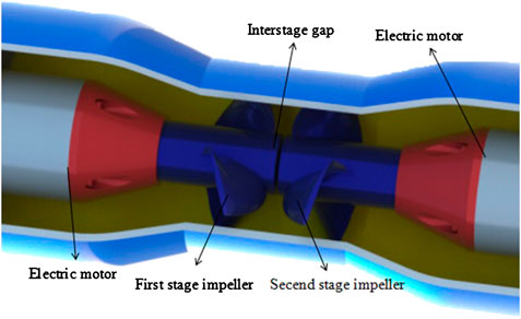
FIGURE 1. Schematic diagram of the unit structure.
Two-Way Counter-Rotating Axial Flow Impeller Hydraulic Design
In order to adapt to the six operating conditions of the tidal power station (forward and reverse power generation, forward and reverse discharge, and forward and reverse pumping), in the process of using the conventional axial flow airfoil, if the impeller is directly rotated in the opposite direction, the head and efficiency of the axial pump will be greatly reduced. The blade is the core component of the turbine machinery. The design quality determines the performance of the turbine machinery. To make the impeller have both high performance in the forward and reverse directions, the existing hydraulic design of the bidirectional axial flow pump blade is generally in accordance with the ordinary axial flow pump. The airfoil used is generally divided into two types. One is a straight blade, also called a flat airfoil, that is, a wing types whose center line is a straight line, as shown in Figures 2A. The airfoil chord length is divided from the center, the airfoil is removed from the water inlet and the airfoil is thickened from the chord length to the two sides to obtain a centrally symmetrical flat airfoil. The other is an “S”-shaped airfoil, that is, an airfoil whose center line is “S”-shaped, as shown in Figures 2B. The airfoil chord length is divided from the center, and the airfoil inlet section is removed, the outlet section is thickened according to the 791-airfoil thickening, and the blade outlet section is rotated and replicated by 180° to obtain a symmetric “S”-shaped blade. Generally, flat airfoils are not used. Due to their poor flow around, cavitation performance is not good. Therefore, this paper studies the “S”-shaped blade. At present, there are many “S”-shaped design methods. In this paper, the axial flow pump blade is used as the initial blade, and the “S”-shape change is performed on the axial flow pump blade with excellent performance.
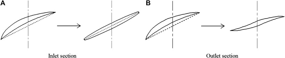
FIGURE 2. Two-way airfoil schematic. (A) Inlet section (B) Outlet section.
Structural Parameter Selection
Table 1 shows the hydraulic design parameters under theoretical conditions. At present, there are many bidirectional pump turbine design methods (Shan, 2013; Wu et al., 2017; Li et al., 2018b). The hydraulic design is designed according to forward and reverse pumping conditions, checking the performance of forward and reverse power generation conditions, or according to forward and reverse power generation conditions, checking the performance of forward and reverse pumping conditions.
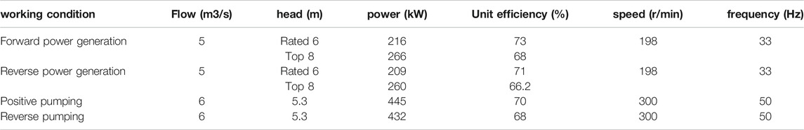
TABLE 1. Basic parameters of hydraulic design.
In this paper, the pump condition is adopted to design the pump. The blade is designed to be centrally symmetric and the counter-rotating impellers are arranged in mirror image. Which makes the performance of the forward pumping condition and the reverse pumping condition basically the same, and the performance under forward and reverse pumping condition is basically the same (Li et al., 2019; Zhang et al., 2019a; Zhang et al., 2019b). Therefore, the design of the two-way counter-rotating axial-flow pump turbine is simplified to the two working conditions of the forward pump and the reverse turbine.
In the Eqs 1, 2:
The research object of this paper is rotary impeller. The design flow rate of single impeller is 6 m3/s, the speed is 300 r/min, and the design head is 2.65 m. According to Eqs 1, 2, the diameter of impeller is D0 = 1300 mm and specific speed is ns = 1,291. The hub ratio

TABLE 2. Relation between blade number and specific speed.
Streamline Method for Design and Calculation of Section
Five cross-sectional airfoil diagrams are drawn according to the axle projection data of Table 3 as shown in Figures 3A. According to the afore mentioned blade airfoil variation method, the “S”-shaped blade (As described in reference (Wang et al., 2020), the simplified ternary flow and lift method is adopted to design the “S”-shaped blade.) airfoil section is made as shown in Figures 3B. In the diagrams, e-e, d-d, c-c, b-b and a-a are axle-surface diagrams of impellers equally divided from hub to rim, and the axle-surface diagrams are divided by contours. According to the section of airfoil, the 2D model of “S”-shaped blade is drawn, as shown in Figure 4.
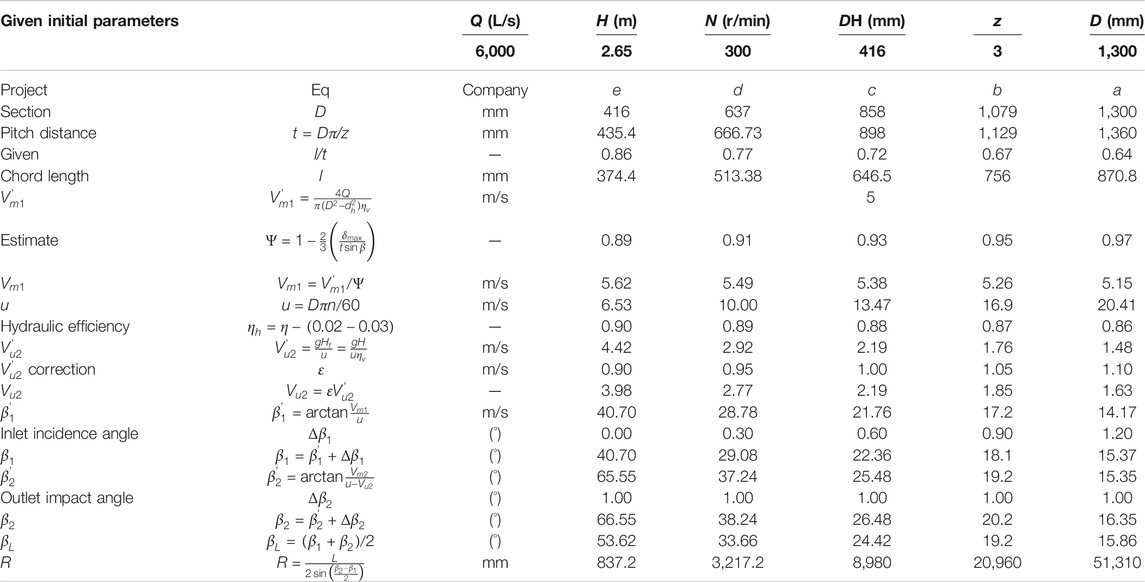
TABLE 3. Axis projection data.
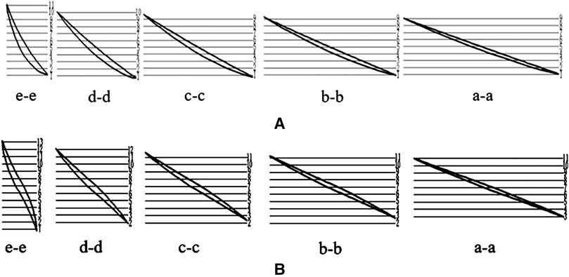
FIGURE 3. Airfoil section transform diagram. (A) According to the above table axial projection data. (B) According to the blade airfoil change method.
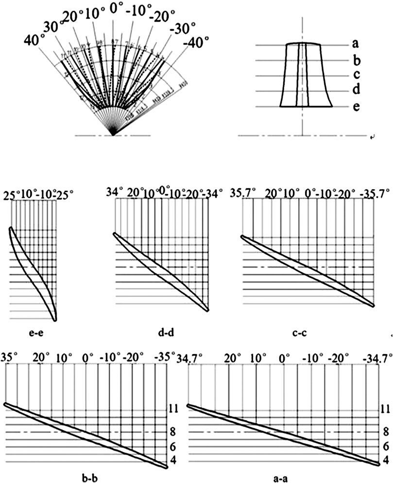
FIGURE 4. “S”-shaped blade.
Modeling of “S”-Shaped Blade
The axial plane expansion diagram of the blade is divided by contour lines as shown in Figures 5A and B. Record the points on the five airfoil sections and the back contour on the woodwork diagram in the table, as shown in attached Table 4. From the impeller hub to the rim, the airfoil sections 5-1, 4-1, 3-1, 2-1, and 1-1 are sequentially plotted on the contour line of the working surface, and records 5-2, 4- 2, 3-2, 2-2, 1-2 as the points on the back-contour line. L/mm is the distance from the working surface of the airfoil contour line and the point on the back side to the center line of rotation. R/mm is the radius of the airfoil cylindrical section. Z/mm is the distance from the contour line to the centerline of the shaft surface. And θ/° is the circumferential curvature of the L transformation. The data of the working surface and the upper airfoil point are imported into the CREO drawing software through the offset coordinate system to obtain the points of the five airfoil sections and the back side. The spatial three-dimensional data points and models of the blade are obtained by line connection, scan mixing, merging, and materialization as shown in Figures 6A, B.
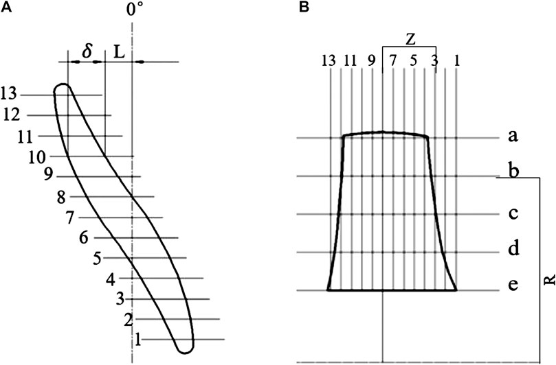
FIGURE 5. “S”-shaped blade expansion view (A) and axial view (B)
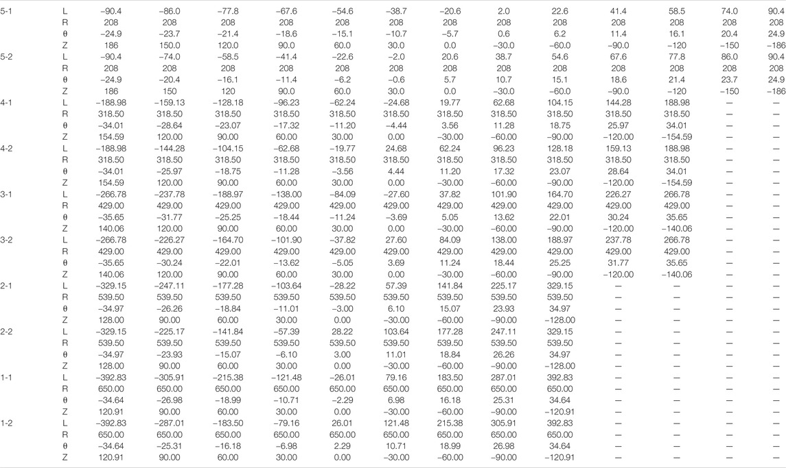
TABLE 4. “S” -airfoil section data points.
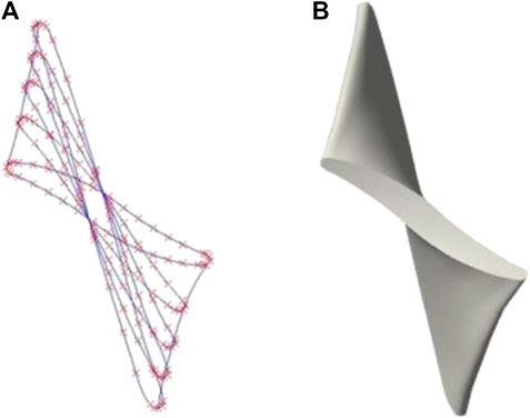
FIGURE 6. Three-dimensional solid modeling of blades. (A) Three-dimensional spatial data points. (B) Model.
The calculation equation of the working face points is as follows:
The calculation equation of the back points is as follows:
In Eq. 4, L is the distance from the airfoil edge to the axis of the blade axial projection diagram.
Effect of Inter-Stage Clearance of Different Impellers on Performance
Due to the opposite rotating impeller rotation direction, dynamic-dynamic interference will occur between the rotors. If the distance between the rotors is too close, serious interference will occur, which will greatly affect the performance of the unit. And the distance between the rotors is too long, the instability of the unit will increase. Studies have confirmed the effect of the axial distance between the two stages of the axial fan on the fan. They concluded that the effect of this distance on the static pressure rise was stronger at partial flow rates than flow rates. The axial distance has a slight influence on the static pressure rise of the front rotor. As the distance increases beyond the 1.25 average chord length of the front rotor blade, the static pressure of the rear rotor gradually decreases. It can be seen that the inter-stage clearance has a great influence on the performance of the unit. Therefore, in order to improve the performance of the unit, it is first necessary to determine the range of the gap between the rotating sub-stages. Choosing an appropriate distance can not only ensure the performance of the unit but also keep the unit stable. The schematic diagram of the gap between the rotating sub-stages is shown in Figure 7. DL represents the inter-stage gap width, and L represents the axial length of the single impeller body. For DL1 = 0, DL2 = 0.25L, DL3 = 0.5L, DL4 = 0.75L, DL5 = 1.0L, DL6 = 1.25L, DL7 = 1.5L, DL8 = 2.0L, modeling and numerical simulation are carried out under the eight rotor inter-stage gaps respectively. The influence of different rotor inter-stage gaps on the performance of the unit are analyzed and studied. The data of the pump and the working condition of the turbine were obtained by the data statistics software.
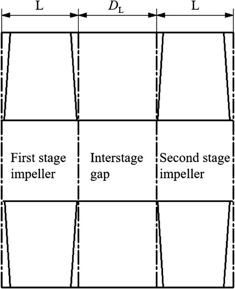
FIGURE 7. Inter-level gap diagram.
Three-Dimensional Modeling and Mesh Generation of Counter-Rotating Turbine Fluid Domain
The ICEM meshing software is used to mesh the fluid domains shown in the above figure. Considering the number of computational model grids, the number of optimized design models, and the better convergence of the computational model, a tetrahedral unstructured grid is used for the fluid domain waters as shown in Figure 8. Taking the inter-stage gap of DL = 1.0L as an example, the grid independence check is performed. When the number of computational model grids exceeds 7.16 million, the head change is less than 1%. In order to save computing resources and take into account the calculation accuracy, the number of grid units in the water inlet section, the first stage impeller, the secondary impeller and the outlet section of the fluid domain is 2.38 million, 800,000, 800,000, 2.38 million, respectively. The grid size setting is consistent with other fluid domains.
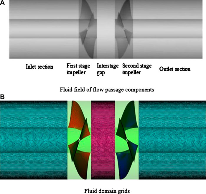
FIGURE 8. Flow field and meshing of flow passage components. (A) Fluid field of flow passage components. (B) Fluid domain grids.
The Setting of Boundary Conditions for Pump and Turbine Working Conditions
Using the ANSYS CFX 18.1 full implicit multi-coupling multi-grid linear solver, the Reynolds average momentum equation is used to describe the incompressible flow in the flow channel, and the turbulence model uses the RNG k-
Effect of Inter-Stage Gap on External Characteristics
Figures 9A, B are the pump head and efficiency curves for the gap between different stages. In Figures 9A, the overall curve of the lift under pump conditions, 1.00L>2.00L = 1.50L = 1.25L>0.75L > 0.5L > 0.25L > 0.00L, the pump head gradually increases with the increase of the inter-stage gap. When DL = 1.00L, the head reaches the maximum under full flow conditions. As the gap between the stages continues to increase, the curves at 1.25L, 1.50L and 2.00L are basically coincident, which are lower than DL = 1.00L. It shows that the pump head does not increase when the gap between the stages exceeds 1.00L, but it is lower than 1.00L. In Figures 9B, the highest efficiency under full-flow conditions is also at DL = 1.00L. Under small flow conditions, the efficiency of the gap between the stages increases in a staggered way, and the lowest is at 0.25L (Figure 10 shows that: when the inter-stage gap increases to 0.25L, three vorticity bands appear at the inter-stage gap, which extends from the first stage impeller to the secondary impeller. The annular vorticity at the inlet of the secondary impeller decreases, and most of them are concentrated in the back of the secondary impeller blades and vanishes along each blade at the exit. So, the efficiency of 0.25L drops abnormally when Q = 5.4). Under the large flow conditions, the gap between the different levels starts to decline when it reaches its peak value. The gap on the curve remains the highest at 1.00L and the lowest at 0.00L. The highest efficiency values in the remaining gaps is in the middle position, indicating that the efficiency of the pump condition no longer increases when the inter-stage gap exceeds 1.00L, but is lower than 1.00L.
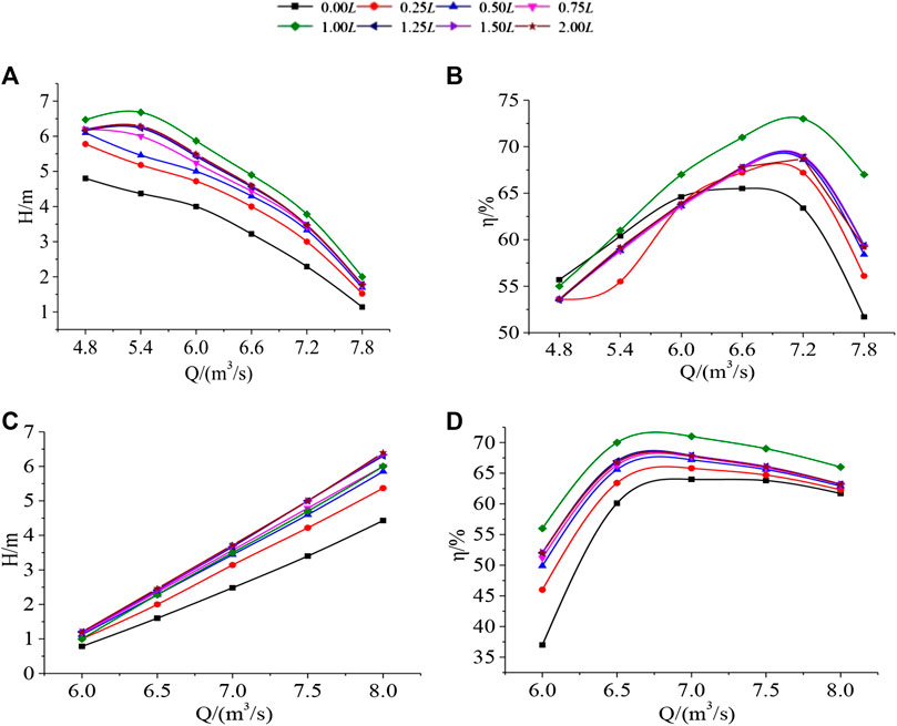
FIGURE 9. Performance curves of pumps and turbines with different inter-stage clearances. (A) the pump head. (B) the pump efficiency. (C) the head curves of the turbine. (D) the efficiency curves of the turbine.
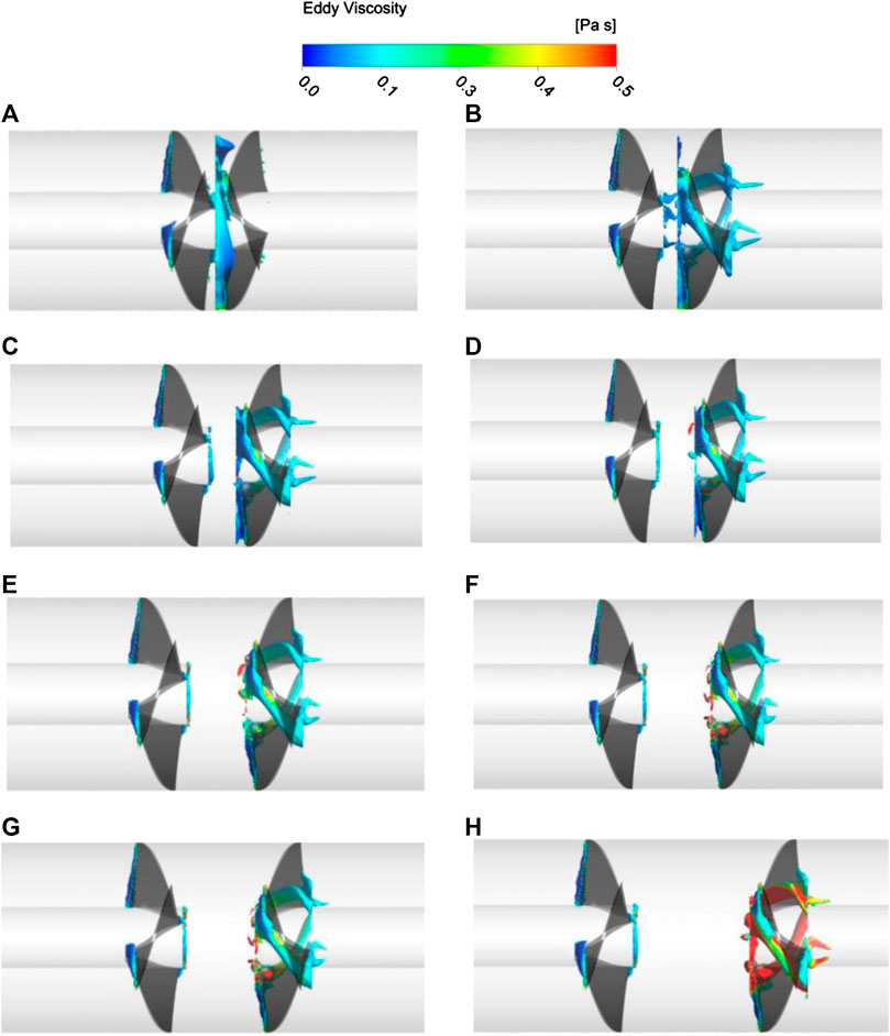
FIGURE 10. Vortex distribution at counter-rotating impeller with different inter-stage clearances. (A)DL1 = 0.00L(B)DL2 = 0.25L(C)DL3 = 0.50L(D)DL4 = 0.75L(E)DL5 = 1.00L(F)DL6 = 1.25L(G)DL7 = 1.50L(H)DL8 = 2.00L
Figures 9C, D are the head and efficiency curves of the turbine operating conditions under different inter-stage gaps. In Figures 9C, the overall head of the turbine under hydraulic conditions is 2.00L = 1.50L = 1.25L>1.00L = 0.75L>0.5L > 0.25L > 0.00L, and the head gradually increases with the increase of inter-stage gap. The curves are basically coincident at 1.25L, 1.50L, 2.00L, and the head is basically stable when the inter-stage gap exceeds 1.25L. In Figures 9D, the overall efficiency curve of the turbine under operating conditions is 1.00L>2.00L = 1.50L = 1.25L>0.75L > 0.50L > 0.25L > 0.00L, and the efficiency increases with the increase of the inter-stage gap. The maximum efficiency curve under full flow conditions is 1.00L, and the curves at 1.25L, 1.50L, and 2.00L are basically coincident, indicating that the head is basically stable when the inter-stage gap exceeds 1.00L.
In summary, except for the turbine head, the highest values of the other working conditions are on the 1.00L curve, indicating that the inter-stage spacing DL has the best performance in the vicinity of the axial width L of the impeller.
Analysis of Internal Flow in Inter-Stage Gaps
The influence of the inter-stage impeller on the performance of the turbine is analyzed from the internal flow angle. Taking the pump working condition as an example, the vorticity analysis and the internal pressure analysis of the impeller are performed under the gap between different stages of the design working condition. From the distribution of the vorticity area, it can be seen that the inter-stage gap has a serious influence on the secondary impeller. The Plane analysis pressure change is established in the middle of the secondary impeller. The eddy current intensity is expressed by the eddy viscosity, and the internal pressure change of the impeller is represented by the total pressure. The vorticity distribution of the unit with eight inter-stage gaps and the internal pressure distribution of the secondary impeller shaft section are shown in Figures 10, 11. In Figures 10A–H respectively indicate the inter-stage gap DL1 = 0.00L, DL2 = 0.25L, DL3 = 0.50L, DL4 = 0.75L, DL5 = 1.00L, DL6 = 1.25L, DL7 = 1.50L, DL8 = 2.00L.
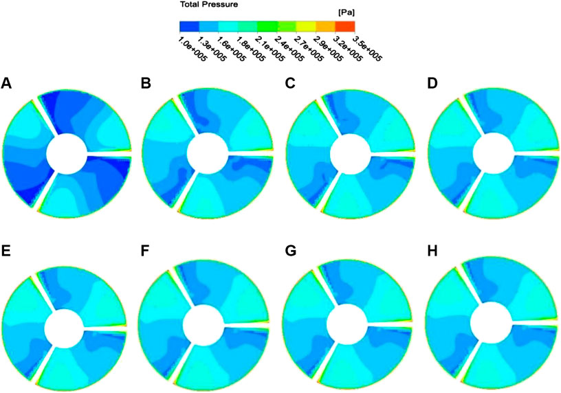
FIGURE 11. Internal pressure distribution in the shaft section of the secondary impeller with different inter-stage gaps. (A)DL1 = 0.00L(B)DL2 = 0.25L(C)DL3 = 0.50L(D)DL4 = 0.75L(E)DL5 = 1.00L(F)DL6 = 1.25L(G)DL7 = 1.50L(H)DL8 = 2.00L
In Figure 10, the left side of the unit is filled with water, and the right side is filled with water. The black area on the left side is the first stage impeller, and the black area on the right side is the secondary impeller. From the vorticity distribution, the vorticity distribution in other clearance conditions is roughly the same, except when the inter-stage clearance is zero. The vorticity at the first stage impeller is mainly concentrated at the inlet edge of the impeller working face and the inlet edge of the impeller. The vorticity at the secondary impeller is concentrated in the inlet side and the back area of the impeller working face, extending from the inlet side to the outlet side in a banded region. When the inter stage gap is zero, the vorticity at the secondary impeller is distributed annularly around the impeller inlet, and most of them is concentrated between the secondary impeller blades and the blades. When the fluid from the forward rotation of the first stage impeller enters the secondary impeller, one part of the fluid is accelerated by the reverse rotation of the secondary impeller working surface, while the other part of the fluid directly impacts on the secondary impeller working surface. Two parts of the fluid in the middle area of the blade collision vortex (Yun et al., 2020a). When the inter-stage gap increases to 0.25L, three vorticity bands appear at the inter-stage gap, which extends from the first stage impeller to the secondary impeller. The annular vorticity at the inlet of the secondary impeller decreases, and most of them are concentrated in the back of the secondary impeller blades and vanishes along each blade at the exit. The impeller blades are on the back side and disappear along the respective vanes at the outlet end. As the gap between the stages continues to increase, the vorticity at the gap basically disappears, and the annular vorticity at the inlet of the secondary impeller becomes less and less, and there is only a small amount of vortex at the inlet.
Figure 11 pressure cloud diagram of secondary impeller intermediate shaft section (the impeller rotation direction is counterclockwise). The pressure on the cut surface of the impeller body increases gradually from the back of the blade to the working surface, and the pressure near the back of the blade is about 1.0∼1.3 atm, the pressure near the working surface is about 1.6∼1.8 atm. When the gap between the stages is zero, the range of the low-pressure area on the back side of the blade is large, and the range of the high-pressure area at the working surface is small. When the inter-stage gap is between 0.25 and 2.00L, the low-pressure area at the back side of the blade rises by 0.3 atm compared with the zero gap, the high-pressure area at working face of the blade increases by 1.6~1.8 atm, and the pressure range of 1.3∼1.6 atm is also doubled compared with the zero gap. Combined with the vorticity analysis, when the inter-stage gap is too small, the first stage impeller forward rotating out of the fluid into the secondary impeller. Some fluid quickly enters the secondary impeller working surface and is accelerated by the reverse rotation. The other part of the fluid directly impacts the working surface of the secondary impeller. This causes a large number of vortices to accumulate at the secondary impeller, and the overall pressure in the secondary impeller is lower than other clearance conditions.
Discussion
The hydraulic design of the “S”-shaped blade for the two-way counter-rotating axial-flow pump turbine is carried out, and the influence of the gap between different impeller stages on the performance of the unit is calculated and analyzed. Both the head and efficiency increase with the increase of the inter-stage gap and no longer increase when it exceeds 1.00L. Combined with the vorticity analysis, when the inter-stage gap is too small, the fluid that is rotating forward from the first stage impeller enters the secondary impeller. A part of the fluid quickly enters the secondary impeller working surface and is accelerated by the reverse rotation. The other part of the fluid is directly impacted on the working surface of the secondary impeller, causing a large number of vortices to accumulate at the secondary impeller, and the overall pressure in the secondary impeller is lower than other clearance conditions.
Conclusion
In this paper, the hydraulic design of the two-way counter-rotating axial-flow pump turbine of the tidal power station is designed. Two common counter-rotating unit structures are designed for the tidal power station, and the influence of the gap between the impeller stages on the performance is calculated and analyzed. The main conclusions are as follows:
(1) The head gradually increases with the increase of the inter-stage gap under pump conditions. When the DL = 1.00L, the head reaches the maximum under the full flow condition. With the inter-stage gap continues to increase, the curves at 1.25L, 1.50L, 2.00L are basically coincident, and are lower than DL = 1.00L. It shows that the pump head will no longer increase when the inter-stage gap exceeds 1.00L, and the highest efficiency point under full flow condition is also at DL = 1.00L, and when the inter-stage gap exceeds 1.00L, the pump operating efficiency does not increase any more.
(2) The head gradually increases with the increase of the inter-stage gap under turbine operating conditions. The curves are basically coincident at 1.25L, 1.50L, 2.00L, and the head is basically stable when the inter-stage gap exceeds 1.25L. On the overall efficiency curve, 1.00L > 2.00L = 1.50L = 1.25L > 0.75L > 0.50L > 0.25L > 0.00L, the efficiency increases with the increase of inter-stage gap, and the highest efficiency curve under full flow condition is 1.00L, and the curves at 1.25L, 1.50L, 2.00L are basically coincident, indicating that the head is basically stable when the inter-stage gap exceeds 1.00L.
(3) When the inter stage is zero, the vorticity at the secondary impeller is distributed annularly around the impeller inlet, and most of them are concentrated between the secondary impeller blades and the blades. On the cut surface of the secondary impeller body, the low-pressure area on the back of the blade is larger, while the high-pressure area on the working face is smaller. The vorticity decreases with the increase of inter stage gap, the area of low-pressure on the back of the blade on the section surface of the secondary impeller becomes smaller, and the area of high-pressure on the working face becomes larger.
(4) It is not the best point when the gap between the stages is too small or too large. When the inter-stage gap is too small, the dynamic-moving interference of the counter-rotating impeller is severe, and the vorticity of the secondary impeller is excessively accumulated, which seriously affects the performance of the unit. When the inter-stage clearance increases to near the axial width of a single reel body, the performance of each working condition is optimal. When the inter-stage gap continues to increase, the performance of each working condition decreases slightly.
Data Availability Statement
The original contributions presented in the study are included in the article/supplementary materials, further inquiries can be directed to the corresponding author/s.
Author Contributions
WX: Methodology, Software. LB: Writing‐Reviewing and Editing. LY: Data curation, Writing-Original draft preparation. ZY: 3D modeling design. ZR: Supervision, Methodology, Investigation. LY: Investigation, Visualization, Conceptualization. FQ: Software, Validation.
Funding
This work was funded by the China Postdoctoral Science Foundation Funded Project (Grant No.2019M651734), National Youth Natural Science Foundation of China (Grant No.51906085), Jiangsu Province Innovation and Entrepreneurship Doctor Project (2019), Zhejiang Postdoctor Project (2019). This work was also supported by Key R & D programs of Jiangsu Province of China (BE2018112), National Key R & D Program of China (2018YFB0606105).
Conflict of Interest
The authors declare that the research was conducted in the absence of any commercial or financial relationships that could be construed as a potential conflict of interest.
References
Cao, L., Watanabe, S., Imanishi, T., and Furukawa, A. (2012). On high efficiency operation of contra-rotating axial flow pump with rotational speed control toward effective energy saving. IOP Conf. Ser. Earth Environ. Sci. 15 (4), 042027. doi:10.1088/1755-1315/15/4/042027
Cao, L., Watanabe, S., Momosaki, S., Imanishi, T., and Furukawa, A. (2013). Low speed design of rear rotor in contra-rotating axial flow pump[J]. Int. J. Fluid Mach. Syst. 6 (2), 105–112. doi:10.5293/ijfms.2013.6.2.105
Clarke, J. A., Connor, G, Grant, A., Johnstone, C., and Ordonez-Sanchez, S. (2010). Analysis of a single point tensioned mooring system for station keeping of a contra-rotating marine current turbine[J]. IET Renew. Power Gener. 4 (6), 473–487. doi:10.1049/iet-rpg.2009.0209
Furukawa, A., Shigemitsu, T., and Watanabe, S. (2007). Performance test and flow measurement of contra-rotating axial flow pump. J. Therm. Sci. 16 (1), 7–13. doi:10.1007/s11630-007-0007-4
Gao, X. (2019). Study of flow characteristics of draft tube of tidal power station[J]. J. Wuhan Univ. 52 (07), 594–599. doi:10.14188/j.1671-8844.2019-07-005
Gao, Y., Li, Y., and Zhang, H. (2016). Prospect of tidal power generation technology[J]. J. State Grid Tech. College. 19 (06), 60–62+73.
Gao, Z., Yang, X., Zhou, N., et al. (2019). Series of researches on and development of self-contained bulb tubular turbine-generator unit[J]. Mech. Elect. Tech. of Hydropower Station. 42 (06), 1–3+71. doi:10.13599/j.cnki.11-5130.2019.06.001
Gongzheng, X., Ding, E., and Tang, D. (2006). A design method for contra- rotating propeller by lifting- surface method[J]. J. Ship Mech. (02), 40–46.
Han, F., and Jin, Y. (2006). Research on hydraulic performance of twin runners with counter rotation for hydro turbine[J]. Water Resour. Power. (05), 37–39+99.
Joly, M., Tom, V., and Guillermo, P. (2013). “Full design of a highly loaded and compact contra-rotating fan using multidisciplinary evolutionary optimization,”in Turbo Expo: power for Land, Sea, and Air. American Society of Mechanical Engineers (ASME) turbine technical conference and exposition, San Antonio, TX, June 3–7, 2013, 55232.
Kehsik, M., Chang, B., and Seo, H. (2009). Study on the contra-rotating propeller system design and full-scale performance prediction methodin rapid hull form generation. Int. J. of Naval Arch.and Ocean Eng. 1 (1), 29–38. doi:10.3744/JNAOE.2009.1.1.029
Kreitmair, M. J., Draper, S., Borthwick, A. G. L, and van den Bremer, T. S. (2019). The effect of uncertain bottom friction on estimates of tidal current power. R. Soc. open sci. 6 (1), 180941. doi:10.1098/rsos.180941
Lee, S.-K., Jang, B.-S., and Ahn, J.-H. (2018). Corrosion monitoring of world's largest tidal power plant[J]. Mater. Perform. 57 (11), 48–52.
Li, D., Qin, Y., Zuo, Z., Wang, H., Liu, S., and Wei, X. (2019). Numerical simulation on pump transient characteristic in a model pump turbine[J]. J. Fluids Eng. ASME. 141 (11), 1–22. doi:10.1115/1.4043496
Li, H., Zhang, P., and Wan, Y. (2018a). Analysis of over vibration of turbine guide bearing for bulb tubular unit[J]. Electric Engineering. (16), 62–63+66.
Li, W., Leilei, J., Shi, W., Ping, Y. F., Zhou, L., and Jiang, X. P. (2018b). Effect of a nonuniform radial/axial tip clearance on the flow field in a mixed-flow pump[J]. Strength Mater. 50 (1), 137–145. doi:10.1007/s11223-018-9952-2
Liu, B., Li, J., and Wang, L. (2018). Research and development of tidal power generation in China[J]. Hydropower and New Energy. 32 (11), 1–6. doi:10.13622/j.cnki.cn42-1800/tv.1671-3354.2018.11.001
Muis, A., Sutikno, P., Suwono, A., and Hartono, F. (2015). Comparative study on performance of very low head axial hydraulic turbine using a single rotor and a contra-rotating rotor. Appl. Mech. Mater. 758, 165–172. doi:10.4028/www.scientific.net/amm.758.165
Peng, D., Zhang, J., and Zheng, J. (2017). Predictions for dynamic tidal power and associated local hydrodynamic impact in the Taiwan strait, China. J. Coast Res. 33 (1), 149–157. doi:10.2112/JCOASTRES-D-16-00068.1
Shinpei, M., Usami, S., Watanabe, S., and Furukawa, A. (2010). Numerical simulation of internal flow in a contra-rotating axial flow pump[J]. IOP Conf. Ser. Earth Environ. Sci. 12, 012046. doi:10.1088/1755-1315/12/1/012046
Shan, D. (2013). Hydraulic design and characteristic analysis of bidirectional axial flow pump model[D]. Wuhan, China: Huazhong University of Science and Technology.
Shi, Y., Yang, B., Kou, Z., et al. (2019). Analysis of pipe network matching and energy consumption in different ventilation modes of contra-rotating[J]. Coal Technol. 38 (01), 136–139. doi:10.13301/j.cnki.ct.2019.01.047
Shigemitsu, T., Takano, T., Furukawa, A., Okuma, K., and Watanabe, S. (2005). Pressure measurement on casing wall and blade rows interaction of contra-rotating axial flow pump[J]. J. Therm. Sci. 14 (2), 142–149. doi:10.1007/s11630-005-0025-z
Shigemitsu, T., Takeshima, Y., Ogawa, Y., and Fukutomi, J. (2016). Internal flow of contra-rotating small hydroturbine at off-design flow rates[J]. IOP Conf. Ser. Earth Environ. Sci. 49 (10), 102008. doi:10.1088/1755-1315/49/10/102008
Wang, S., Li, Z., and Li, M. (2020). Simulation and experimental study based on S airfoil impellers of tidal turbines[J]. Manuf. Autom. 42 (04), 110–115+156.
Wang, Z., Yang, X., and Xiao, Y. (2010). Hydraulic performance optimization of bidirectional tidal power turbine[J]. Journal of Drainage and Irrigation Machinery Engineering. 28 (05), 417–421. doi:10.1088/1757-899X/52/5/052022
Wu, Z., He, Y., Shao, Y., et al. (2017). Research on the dynamic characteristics of reversible axial-flow pumps based on fluid-solid coupling[J]. China Rural Water and Hydropower. (05), 188–192.
Xu, H., and Wang, D. (2019). Tidal Power generation process control based on differential game theory[J]. J. Coast Res. 83, 959–963. doi:10.2112/si83-158.1
Xuesong, W. (2017). The research of foil optimization and flow visualization of counter-rotating tidal turbine[D]. Hangzhou, China: Zhejiang University.
Yang, N. (2019). Analysis of factors influencing bulb turbine generator unit vibration[J]. Guangxi Water Resources & Hydropower Engineering. (01), 71–73. doi:10.16014/j.cnki.1003-1510.2019.01.018
Yang, W., Liu, S., and Wu, Y. (2008). Unsteady numerical simulation of contra-rotating Kaplan turbine[J]. J. Eng. Thermophys. 29 (01), 75–77.
Yin, X., and Wang, P. (2010). Exploit of tidal energy and utilization in Jiang Su Province[J]. Shanghai Energy Conservation. (10), 15–19.
Yun, L., Bin, L., Jie, F., Rongsheng, Z., and Qiang, F. (2020a). Research on the transient hydraulic characteristics of multistage centrifugal pump during start-up process[J]. Front. Energy Res. 8, 76. doi:10.3389/fenrg.2020.00076
Yun, L., Zhu, R., and Wang, D. (2020b). A cavitation performance prediction method for pumps PART1-proposal and feasibility[J]. Nuclear Eng. and Tech. 52 (11), 2471–2478. doi:10.1016/j.net.2020.04.007
Zhang, N., Liu, X., Gao, B., and Bin, X. (2019a). DDES analysis of the unsteady wake flow and its evolution of a centrifugal pump[J]. Renew. Energy. 141, 570–582. doi:10.1016/j.renene.2019.04.023
Zhang, N., Liu, X., Gao, B., Xiaojuna, W., and Bin, X. (2019b). Effects of modifying the blade trailing edge profile on unsteady pressure pulsations and flow structures in a centrifugal pump[J]. Int. J. Heat Fluid Flow. 75, 227–238. doi:10.1016/j.ijheatfluidflow.2019.01.009
Keywords: tidal energy, two-way counter-rotating, pump turbine, inter-stage gap, “S”- shaped blade, hydraulic optimization
Citation: Xiuli W, Bin L, Yang L, Yan Z, Rongsheng Z, Yun L and Qiang F (2020) Hydraulic Optimization of Two-Way Counter-rotating Axial Flow Pump Turbine. Front. Energy Res. 8:577232. doi: 10.3389/fenrg.2020.577232
Received: 29 June 2020; Accepted: 20 October 2020;
Published: 23 November 2020.
Edited by:
Joshua Dominic McTigue, National Renewable Energy Laboratory (DOE), United StatesCopyright © 2020 Xiuli, Bin, Yang, Yan, Rongsheng, Yun and Qiang. This is an open-access article distributed under the terms of the Creative Commons Attribution License (CC BY). The use, distribution or reproduction in other forums is permitted, provided the original author(s) and the copyright owner(s) are credited and that the original publication in this journal is cited, in accordance with accepted academic practice. No use, distribution or reproduction is permitted which does not comply with these terms.
*Correspondence: Long Yun, longyun@ujs.edu.cn