The Effects of Defects and Damage in the Mechanical Behavior of Ti6Al4V Lattices
 Russell Goodall1*
  Everth Hernandez-Nava1
  Sarah N. M. Jenkins1 Lorna Sinclair1 Emily Tyrwhitt-Jones1 Mohammad A. Khodadadi1 Donald H. Ip2
  Hassan Ghadbeigi2
- 1Department of Materials Science and Engineering, The University of Sheffield, Sheffield, United Kingdom
- 2Department of Mechanical Engineering, The University of Sheffield, Sheffield, United Kingdom
With recent advances in manufacturing methods for metals with defined, complex shapes, the investigation of metallic lattice materials (metals containing significant porosity with a regular arrangement of the solid, frequently in the form of thin structural members or struts) has become more common. These materials show many interesting properties, and may have the capacity to be more highly engineered and optimized for a given application than the random structures of other microcellular metals, such as metallic foams and sponges, permit. However, the novel structure brings new structure-properties correlations to bear on the mechanical behavior of the materials. This paper examines one type of lattice, made from titanium alloy (Ti6Al4V) and fabricated by Electron Beam Melting (EBM), a material which typically shows only limited plasticity on deformation. The overall mechanical response is governed by the cooperative deformation of a very large number of individual struts that make up the lattice, and thus there is great potential for significant impact from damage arising due to defects in individual struts in the assembly. We explore the effect of simulated processing defects (missing struts) on the lattice properties, and how deformation and failure is distributed across the lattice after the onset of failure. To gain knowledge of how lattices deform, samples of various geometries, designed to probe compression, indentation-compression and tension (in the form of bending) are produced and tested under Digital Image Correlation (DIC) mapping. The understanding gained here will be of great use in designing new metallic lattice structures with greater damage tolerance and resistance to failure.
Introduction
Advances in novel manufacturing methods, such as Additive Manufacturing (AM) techniques (Murr et al., 2012; Frazier, 2014), have led to the ability to create porous metal structures with great control over the form the material takes. Porous metals can be desirable to achieve specific behaviors, such as the ability to be crushed, to permit fluid transport or to allow an extra level of tailorability (that of the structure) to obtain the desired properties of the material (Goodall, 2013). AM, with the ability to leave spaces or retain regions of unmelted powder that can be removed from the structure after processing, is well-adapted to the needs of porous metal production, especially those based on regular structures (although stochastic structures may also be produced (Hernandez-Nava et al., 2015); while production of such lattices is possible without AM (e.g., by using sheet metal manufacturing techniques, for example; Kooistra and Wadley, 2007; Queheillalt and Wadley, 2009), or only using AM to assist with creating investment and molds used in processing (Chiras et al., 2002), it is much facilitated by the direct use of the technique. Nevertheless, it has to be recognized that AM methods impose certain constraints over the physical structure of the material processed, both at the level of the part geometry, and also on the microstructure and the defect population (Tammas-Williams et al., 2015).
There is scope for much exploration of different possible porous forms. While not without limits, the range of structures with the potential to be made by metal AM is much wider than the examples already reported. Complex lattices with highly engineered designs have been produced (for example Amendola et al., 2015, 2016; Dumas et al., 2017), and relatively well-characterized forms such as the diamond structure (where the position of the struts replicates the tetrahedral orientations of the atomic bonds in the structure of the diamond form of carbon) are the more common. This type of structure has also been adapted to make more complex designs, such as density-graded lattices (Grunsven et al., 2014), and similar lattices can be designed to be elastically isotropic (Xu et al., 2016). Lattices have the potential to be highly engineered, creating materials with combinations of mechanical properties and density that are not found in other materials, as indicated by several theoretical studies of lattice geometries [see e.g., (Fleck et al., 2010; Berger et al., 2017)] and the review in Schaedler and Carter (2016). As well as forming parts which can be exploited for their good weight-specific properties, AM manufactured lattices could serve in specialized applications, such as biomedical implants (Wally et al., 2015; Elahinia et al., 2016).
Analysis of mechanical performance of as-manufactured AM parts is however vital; in particular, it is important to know more about how the behavior of lattices is influenced by microstructure and defects. These are dependent on the processing conditions of the AM methods used, but also potentially the interaction of these with the lattice geometry being made. For example, it is known that such lattices contain porosity as a defect [see for example (Hernandez-Nava et al., 2016)]. Here the effect of severe defects of this type is probed by testing diamond and simple cubic lattices (where the struts are oriented along the edges of a cube) made with the deliberate removal of struts from the build file. The diamond structure lattice is then further tested in a range of loading conditions, combined with Digital Image Correlation (DIC) (Pan et al., 2009) to examine deformation fields and the failure modes, and how they correlate with the structure of the lattices and mechanical properties of the material within them.
Methods
Lattice Design
Lattices created were based on either a “diamond” lattice (an arrangement where the struts are positioned as the interatomic bonds in the unit cell of diamond), or a “simple cubic” arrangement (where struts lie along the edges of a cube, and cubes are arranged adjacently to each other) of struts, (see Figure 1). In each case the struts were designed to be cylinders with 1 mm diameter, and each sample was a cube composed of 6 unit cells in each direction (5 in the case of the simple cubic structure), making them well above the limit found for consistent properties in metallic lattices (Morrish et al., 2017). Each side length of the lattice sample was 25 mm, and solid blocks of material with a dimension of 27 × 27 × 5 mm were also incorporated into these lattices (at the top and bottom edges) to make a sandwich structures; this was done in order to improve the contact at the test machine anvil surface and the samples. The blocks were manufactured simultaneously with the lattice in the form of the same part. One set of samples was made without the blocks for assessment in compression with DIC observation, to ensure the failure mode was not affected by the blocks.
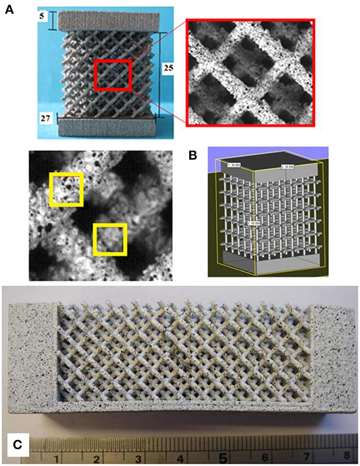
Figure 1. (A) an undefected diamond lattice compression sample with integrated solid block on the upper and lower faces and a magnified view of the speckle pattern used for DIC and subsets used to analyze the images compared with the diameter of struts, (B) an example of the input file used in the EBM process, this time showing a simple cubic structure lattice, and (C) a bend sample consisting of diamond lattice structure and dense metal, designed so the neutral axis lies on the interface.
These basic lattice designs were taken and in some cases defects were deliberately introduced. These took the form of struts within the lattice deleted manually from the CAD file, representing the effect of a serious defect essentially removing the load supporting capacity of the strut. Such samples were produced with various percentages of the struts removed at random (by a random number generation method and manual deletion of corresponding struts); 1, 5, and 10% for the diamond structure and 1, 3, 5, and 7% for the simple cubic. A single unit cell of the diamond structure contains 16 struts, so the samples contained 3,456 struts. Samples with 1, 5, and 10% levels of defects therefore have 35, 173, and 346 struts removed (rounding up to the nearest whole number of struts), respectively. A simple cubic unit cell has only three struts, and so the actual number removed was in this case lower to achieve comparable percentage reductions. At even the lowest levels, this is likely to represent a much higher defect concentration that would occur in realistic processing of such lattices by additive manufacturing methods like EBM (it should be noted that in all the samples processed in this work, no observations of fully missing or broken struts on building were made), but the high level will ensure that measureable effects are generated within a tractable number of test samples, and allow the overall trends to be identified.
Two different sets of defected samples were created for each defect concentration, where in each case the defects were placed in random locations as determined by the random number generation process, with first the structure for 1% missing struts being made, and then further struts being removed from this structure to create 5% and subsequently 10%. Three identical samples of each structure at each defect level were made. The simple cubic lattices were further produced in a series of different strut thicknesses (an effective way to change the density), with nominal strut diameters of 0.8, 1.0, 1.2, and 1.5 mm. When produced these gave lattices with average porosity of 94.4, 92.6, 89.0, and 83.8%, respectively. The stress-strain curves produced on mechanical testing were analyzed to identify the Young's modulus and the 0.2% offset yield strength as characteristics of the elastic and plastic response.
The next part of the investigation was concerned with the distribution of deformation in lattices during mechanical deformation under different loading arragements, particularly once permanent deformation and damage had occurred, and the failure modes shown. Samples consisting of lattice cubes of the diamond structure were made to the same dimensions as those used for the defect investigation (see Figure 1). Additional test samples where the upper dense plate extended only half way across the specimen were also manufactured to introduce an unequal compressive load and an indentation-compression deformation situation, as shown in Figures 6A1,2. The whole section of the top plate is loaded in the former while in the latter the section where the plate was not present is not directly loaded. It was also desired to explore lattice behavior under tension. In order to implement a tensile stress field to the lattice structure, bespoke bending specimens were designed and produced. Bending beams (Figures 1B, 7, 8) were designed in such a way to ensure the lattice structure is in the tensile stress mode, attached to a solid dense layer that would experience the compressive stresses due to bending and provides the required support for the loading mechanism. This was done by using the modulus data determined for the lattice under compression (without defects) and the data of the known modulus of the dense material, then calculating the thicknesses of the two layers (when combined in a bi-material beam) that would result in the neutral axis being positioned at the interface between them when they were loaded in bending. Thus, the dense material would be entirely in compression, and the lattice entirely in tension, albeit with a non-uniform distribution of magnitude.
Lattice Manufacture
Lattice samples were built from Ti6Al4V powder using the standard build settings on an Arcam AB® A2 machine (commercially available EBM equipment). The Ti6Al4V preheat for 50 μm layers was followed by the standard Arcam Ti6Al4V 50 μm layer net theme, comprised of three contour passes followed by a hatch.
Lattice Characterization
Samples were mechanically tested in compression. A Zwick Roell Z050 test rig supporting a 50 kN load cell was used to run compression tests under a displacement-controlled regime, ensuring an initial strain rate of 10−3 s−1. The displacement of the end plates was measured with a Zwick Roell VideoXtens video extensometer with a data capture rate of 25 frames per second. The plates were prepared in order to reduce the AM building surface roughness and generate smooth, flat surfaces to contact the loading rig.
The full field planar strain distribution was also measured for the samples of diamond lattices in the form of compression cubes, cubes which were loaded on only half of their thickness (indentation-compression) and bend samples (Figure 1) during testing using a 2D-DIC to measure the local strain field. The consecutive images recorded using the DIC system were also used to observe the damage mechanisms and identify the local strain values at the observed damage initiation sites. Speckle patterns were painted onto the surface of the samples in order to provide random features for the DIC analysis. The Least Square search algorithm provided by LaVision was used to analyse images using 32 pixels subsets with a step size of 19 pixels. Figure 1A shows the selected subset size in relation to the strut dimensions.
Results and Discussion
Effect of Missing Strut Defects
The samples designed and produced to address the magnitude of the effect of severe defects which might arise during building (building errors, surface roughness related defects, or the concentration of significant levels of porosity) were tested, and the variation in Young's modulus and yield strength with defect concentration for the diamond structure is shown in Figure 2. As well as establishing the potential role of defects in lattice mechanics, this understanding is important for the design of components with lattices, to understand how such defects as might arise statistically during processing will affect performance.
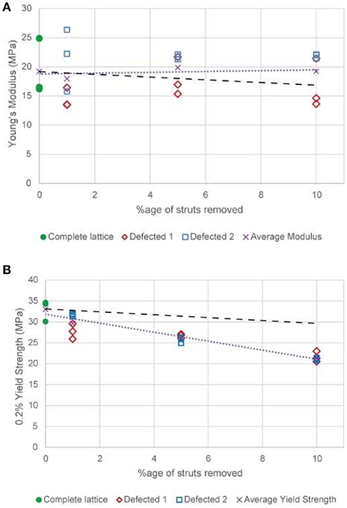
Figure 2. The variation in (A) Young's modulus and (B) 0.2% offset yield strength for diamond structure lattices made with various proportions of missing struts. Defected 1 and Defected 2 represent the two different structures produced by randomly removing struts from the CAD model. The fine dotted trend lines shown represents the best least square fit to the average of all samples at a particular concentration of missing struts. The larger dotted lines represent the predictions of a simple model for the impact of the missing struts, as discussed in the text.
From Figure 2A it can be seen that the effect of the removal of struts, even up to a relatively high level, does not apparently have a consistent effect on the Young's modulus. The trend line for these data is almost horizontal, and there is significant scatter in the data. This indicates that there are factors other than the overall number of missing struts that have a significant effect on the Young's modulus, at least up to the maximum (and relatively elevated compared to the likely occurrence in processing) level of defects explored. The identity of one of these factors is suggested by the observation that the two different random structures formed have a significant, and roughly consistent, difference between their modulus values at all levels of defects. This indicates that for elastic behavior the location of struts removed may be especially significant, with the removal of struts from key areas (which could exist due to irregular strut shape at the microscale and non-uniform load distribution arising from the previously-removed struts) affecting the behavior much more than from others (e.g. those at the surface). This in turn would imply that within the structure some struts could be more heavily loaded than others, and that the diamond lattice (at least in the as-manufactured form, if not in the geometrically perfect version of the original CAD model design) is not optimally mechanically efficient.
In order to make an assessment of the impact of the defects which would be expected theoretically, we begin by treating the lattice as an array of separate volume elements, each with effective mechanical properties. For a perfect lattice, each of these elements has the same response to load, which has an identical stress-strain response to that of the whole lattice. Where a defect is present we assume that the resistance to load is zero, reflecting the binary nature of the defects introduced in this work (i.e., struts are either present or are entirely removed).
The volume elements can be combined in numbers equivalent to the unit cells used, to allow the correct ratio of defects to be introduced. Cells in columns along the loading direction can be combined using a Reuss (equal stress) model, which, under the simple assumption that the defected cell supports no load, gives a zero modulus for the column. Columns can be combined with a Voight (equal strain) model, giving simply that the Young's modulus of the defected material should be equal to (1-f)E, where f is the fraction of defects and E is the Young's modulus of the perfect lattice.
This allows the penalty of different defect concentrations to be estimated, and a line of slope -E is plotted on Figure 2A, starting at the mean value of the complete lattice modulus, to show this effect. This line shows that there would be expected to be a negative trend, which is not clearly seen in the data, however, over the range examined, the magnitude of this trend is actually rather small, and is within both the experimental error range and the range of results produced from the different, random structures. Therefore, the results obtained are consistent with a penalty to the elastic properties of defects of the range predicted.
On the other hand, the plastic deformation results show a clear trend for decreasing strength when an increasing number of struts is removed (see Figure 2B), and the scatter between the different structures, and within repeat tests on the same structure, is much less. This in turn suggests that removing struts has a much greater effect on plastic behavior. The same, simplistic argument can be applied as was used to understand the elastic properties. This indicates that, under an equal stress model, the penalty for defects should be the same, i.e. that the yield stress of defected material should be (1-f)σy, where f is the fraction of defects and σ y is the yield strength of the lattice in the undefected condition. A line of this slope is also plotted on Figure 2B.
In the case of strength, it is clearly seen that the penalty for defects in the material is higher than predicted, with the slope being closer to −3σy than –σy. The reason for this departure is that the mechanics of deformation are more complex than for the simple model in the case of permanent deformation. It is known (e.g., Gibson and Ashby, 1997) that missing cell walls or struts in porous materials can also affect the mode of deformation, with the tendency for defects to contribute to the nucleation and propagation of deformation bands in ordered structures (Silva and Gibson, 1997). Finite element analysis could be one way of further analyzing this effect, though this is likely to be affected by underlying anisotropy of material response, such as that which could arise in titanium alloys where the microstructure has a preferential orientation, and may require specific definitions of the properties of different struts (Rashed et al., 2016). Such modeling may also be rendered more complex by the uneven surface shown by real additively manufactured lattices, which has been suggested previously to be responsible for real lattices not achieving the same level of strength as predicted by FE simulations (Ozdemir et al., 2017), though there has been recent work toward developing advanced FE approaches to incorporate these kinds of structural variations (Lozanovski et al., 2019).
Lattice samples based on a simple cubic lattice, with defects incorporated have also been produced, and, unlike the diamond lattices, have been created at various densities. Testing of these samples gave the results in Figure 3, showing the variation in the offset yield strength with inclusion of artificial defects. Data points plotted are the averages for different defect structures and repeats. As the lattices evidently show very different strength with density variations, the data are normalized here to the offset yield strength of the artificial defect-free lattice of the corresponding density. These data show several things in relation to the defect tolerance of lattices. Firstly, taking the cubic samples of different density collectively, the trend in behavior seems the same in each, indicating that it is the nature of the structure, rather than the amount of porosity or metal, which influences the behavior with regard to defects of this type. This is logical, as in each case a complete strut is removed; if defects of uniform size were used it might be expected that the higher density material would be affected to a lesser extent, by having more remaining metal to support load. The second observation is a striking difference between the trend for the diamond lattice structure and that for cubic. Diamond lattices show a continual, relatively gradual decline in strength with increasing concentration of defects. Cubic lattices on the other hand display an initial sharp fall in strength to less than half the initial value, which is followed by continued gradual decline, with a slope similar to the decline in strength in diamond lattices. Note that the lines in Figure 3 correspond to a linear fit of all points for the diamond lattice data, but just the points for samples with introduced defects for cubic data.
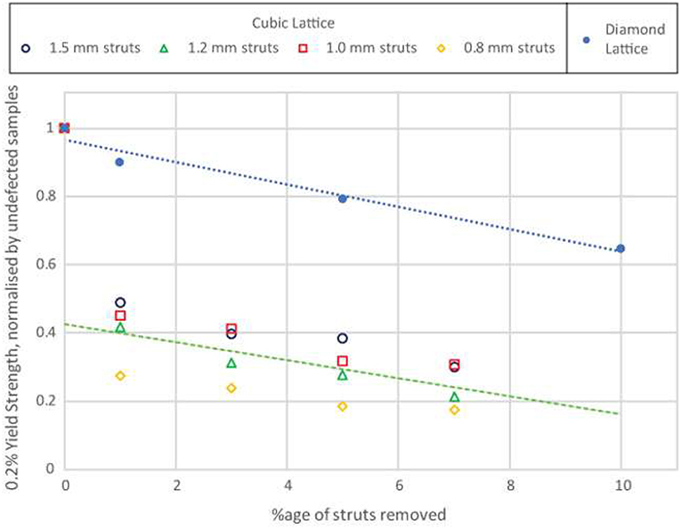
Figure 3. The variation in 0.2% offset yield strength for cubic structure lattices, normalized by defect-free structures, made with various proportions of missing struts, for different densities. Data points are the averages of results from different structures and repeats with the same defect fraction. The trend line shown represents the best fit to the average of all samples at a particular concentration of missing struts.
The large decrease in compressive strength seen with cubic samples containing a low percentage of defects, contrary to the behavior of the diamond lattices, must relate to the geometrical differences between these structures. In a cubic lattice tested in compression along the axis of one of the cube edges, removal of struts may remove struts in the column orientation (i.e., lying along to loading direction), which would previously have been supporting significant load (indeed, for a sample of 5 × 5 × 5 unit cells, removal of 1% of the struts makes it slightly more likely that a strut aligned with the compression direction is removed than that one is not). The effect of this will be to change the mode of failure; rather than depending on the buckling of columns, the mode of the initial permanent deformation will change to the failure of cantilever beams. This change of failure mechanism between artificial defect-free and the lowest level of defects tested could explain the large fall in strength seen. For a diamond lattice, because of the multiple connectivity at nodes along the direction of load transmission, the removal of random struts is less likely to cause such a significant change in the operating failure mechanism. This greater defect dependence of the cubic lattice compared to diamond also agrees with earlier findings (Hernandez-Nava et al., 2016) that the cubic lattice is stronger for a given density, i.e., that it is more mechanically efficient.
The strength of lattice materials of different types therefore seems to be highly dependent on defects. While a theoretical description of the exact influence of defects on mechanisms of deformation is complex, worthy of further study, in this investigation we proceeded to explore the phenomena of the deformation mechanics of lattices in more detail.
Damage Mechanisms and Strain Distribution
In order to explore the mechanisms of deformation and damage in the lattices, a set of samples, including both compression and bending geometry, was made for mechanical testing combined with DIC analysis to measure the developing strain field. The bending samples were tested at the same displacement rate as the compression samples to satisfy the consistency requirements.
Deformation and damage development in samples subjected to compressive loading is shown in Figure 4 (also available as a video online). It has been found that the solid block (which is connected to the struts at the surface nodes) restricts the deformation of the samples at the interface nodal positions. This forces the material to experience a barrelling deformation up to the maximum applied load, where damage initiates. The implemented restriction prevents failure from initiating at the upper or lower contact points, and ensures failure occurs within the body of the structure. Otherwise, the mode of failure and the failure path appear to be comparable to samples tested without the solid block. Damage starts by crack initiation at the nodal position, highlighted in red in Figure 4; however, no sign of catastrophic failure was observed at the struts. Similar deformation patterns were observed in the samples subjected to unequal compression experiments (where the loading is a combination of compression and indentation) wherein the compressive stress was followed by local shear deformation within the structure (Figure 5). Several deformation mechanisms, including tensile, compression and shear, were activated in the latter experimental setup, as the samples passed beyond the uniform compressive state. Although tensile and compressive deformation fields were observed in different parts of the samples, the failure occurred at the nodal positions located inside the localized shear zone.
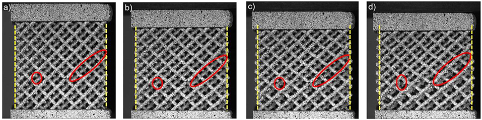
Figure 4. Deformation and damage development in compression (a) undeformed structure, (b) initial buckling mode that shows barrelling effect (vertical lines added to aid observation, (c) damage initiation at the highlighted nodal position, (d) final fracture at the nodes. The video from which these stills were taken is available online.
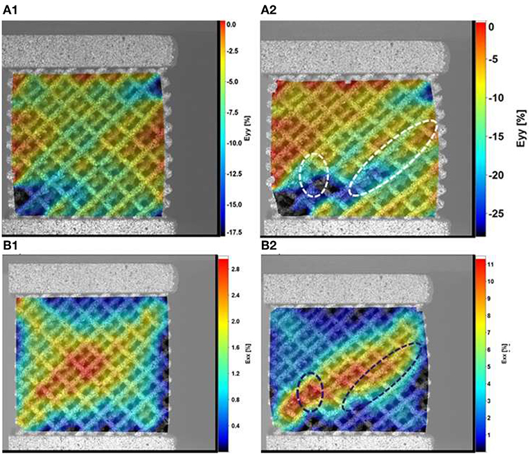
Figure 5. Local strain distribution in y (A1,A2) and x (B1,B2) directions, relative to the test, for samples under compression, (A1,B1) at the maximum compressive force and (A2,B2) at the point of final fracture. The load was applied in the same direction as the build, y direction in the figure (vertical).
The strain distributions in Figure 6 show that the applied forces were transferred to the structure with the maximum equivalent strains measured at nodal positions in contact with solid blocks (Figure 6C1). This is followed by further deformation localization in the regions directly below the upper block. Figures 6A3,4 indicate that struts are bending toward the end of the experiment, leading to higher strain values in x and y directions (in plane directions in the test) at the nodes. According to the strain distributions, failure occurs at about 45° with respect to the loading direction. This shows that the sample does not undergo failure under compressive stress directly (i.e., the failure does not initiate directly under the loaded plate), rather it is a mixed-mode failure, initiated at the interface between the half plate and the struts (the loaded and unloaded regions). This is in accordance with what would be expected, with failure initiating where stress concentration occurs.
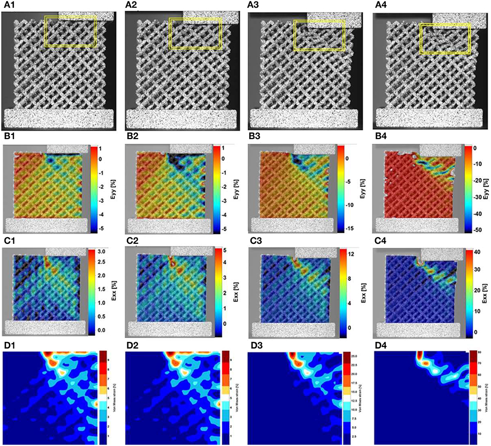
Figure 6. (A1–A4) deformation and damage development in unequal compression samples. Strain distribution in directions y (B1–B4), and x (C1–C4), relative to the test, and (D1–D4) von-Mises strain distribution at various stages of deformation. The load was applied in the same direction as the build, y direction in the figure (vertical).
Figure 7 shows the test setup for the bending experiments before and after failure. This setup is critically important, as the lattice structure is subjected to a tensile stress field (which is difficult to engineer in samples of lattices that can be tested without risk of interface failure) and damage is observed to start from the lower set of cells where maximum tensile stress is expected. A very limited amount of plastic deformation was observed at the solid layer in contact with the loading roller. It should be noted that in this case the samples are imaged in the plane of the build, with the test direction being in plane.
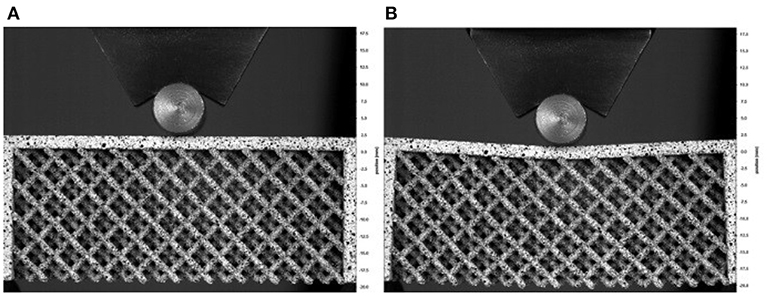
Figure 7. Bending test sample (A) at early stages of the experiment and (B) just before the final failure.
Strain distribution within the lattice structure during the bending experiment is shown in Figure 8 for three different times during the loading cycle which correspond to the start of the test, middle of the test and just before the failure of the sample. According to the results, the in-plane longitudinal strain (Exx, Figures 8A1–3), representative of uni-axial stress at the tensile side of the sample, increases from the start of loading and reaches a maximum value of 5% (measured by DIC) just before fracture. The results show the strain is localized directly below the contact point with the roller where the maximum tensile stress occurs. Additionally, the distribution of the Eyy strain component indicates that the lattice structure is absorbing the applied deformation as the strain concentration point is shifted toward the center of the structure, away from the stress free boundaries. This may indicate that the internal layers of the structure are taking more compressive deformation compared to the free surfaces at the boundaries.
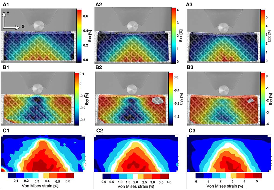
Figure 8. Distribution of (A1–A3) axial strain Exx, (B1–B3) axial Eyy and (C1–C3) von-Mises equivalent strain during the bending experiment showing the maximum local strain of about 5% at the onset of crack initiation and propagation within the structure.
The distribution of equivalent von-Mises strain for the bending samples is shown in Figures 8C1–3. The equivalent strain is throughout localized at the outer layer of the structure and reaches a critical value of 5% just before failure. This value is almost identical to the Exx strain; tensile deformation is considered to be the dominant mode of deformation. Therefore, the investigated lattice structures show very different mechanical behavior dependent on the nature of the applied external load, with higher resistance to failure in compression, where a total deformation of about 10% is reached, compared with tension, where the total deformation is about 5%. These measured values could be used to develop a strain-based failure criterion for more complex loading scenarios, as well as in predicting the damage tolerance of structures made from such lattices.
The presence of the different modes of deformation observed is confirmed, and their effects demonstrated, by examination of the fracture surfaces in the samples (Figure 9). Looking across many broken struts, failure is most frequently observed to occur at the nodes where struts interconnect, where, if the struts are imagined as bending beams [a common description in theoretical models of the deformation of porous materials (Gibson and Ashby, 1997)], the maximum equivalent strains would be expected.
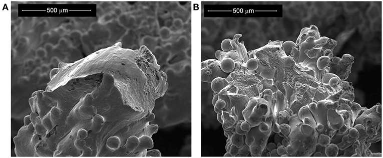
Figure 9. Scanning Electron Microscope images of the post-test failure surfaces in samples deformed by compression (A), and in tension (B), the latter using the bending beam sample approach.
The failure point is typically where a strut meets a node (the root of the strut), and not through the node itself, as this is the site of stress concentration, in a similar way to any macrostructure. Observation of the broken surfaces (such as those in Figure 9) shows limited local plastic deformation under both tensile and compressive loading, with cracking sometimes observed in regions of the strut away from the failure point, though this is difficult to identify consistently and with high confidence, due to the surface roughness. This effect means that struts fail before buckling, which would be theoretically predicted to be the failure mode for many lattice structures (Fan et al., 2009). The high degree of surface roughness is evident (as typically observed in EBM struts in the absence of post-processing treatment (Lhuissier et al., 2016). A significant contribution to this roughness comes from a large number of spherical features of around 50 μm in size, almost certainly particles of the original powder, which were not fully molten and have been incorporated into the strut surface.
The higher surface to volume ratio in lattice materials (i.e., more material in a lattice is within a small number of beam passes of the surface of the struts) may be expected to have an influence on the behavior. This could happen due to the surface roughness, which results in a significant amount of material that is not directly load-bearing. Furthermore, in Figure 9 several regions can be seen where there are canyon-like surface features (similar to the type II surface defects as defined in Lhuissier et al. (2016), most likely formed as material becomes molten with incomplete melting of the solid below, leading to differences in volume and difficulty in the material producing a fully solid continuous strut (Hernandez-Nava et al., 2016). The form of such features could easily develop into cracks, either during cooling due to thermal stresses, or on loading. A high concentration of available crack-like defects could contribute to reduced failure strains in material with limited ductility, as observed here.
A further effect of the surface can be described as a skin effect. The surface region is usually formed by a contour pass that tracks the outline in the layer, while interior spaces are melted in a hatching pattern. This difference in heat input and melt pool shape, combined with additional nucleation points on unmelted powder particles, produces a finer grain structure and weaker texture at the surface, dominating where sections are < 2 mm thick (Antonysamy et al., 2013); true of the entire structure of the lattices examined here. This layer may be more prone to the propagation of cracks and would act to constrain and reduce the ductility of the interior material, in an effect similar to surface hardening. The observation from testing is, as is commonly seen in mechanical tests of EBM titanium lattices, that the ductility of the individual struts is low, and both of the effects described above (surface roughness leading to cracking and the skin effect) would promote the kinds of low-ductility failures seen.
Conclusions
This work investigates the impact of defects, in the form of engineered missing struts, on the mechanical properties of Additively Manufactured (EBM) titanium lattices with the diamond and cubic structures under compressive and tensile loading conditions.
The presence of high levels of missing strut defects, up to 10%, is not found to reduce the elastic modulus of the diamond lattices in a consistent manner; the effect appears sensitive to the precise location of such defects. On the other hand, there is a systematic decrease in strength as defect populations are increased. As shown by the comparison with cubic lattices, this decrease appears not to be influenced by the lattice density (at least when the defects comprise whole struts) but the connectivity of the lattice along the loading direction and the potential for removal of key struts to change the failure mechanism can have a large impact. This further suggests that the diamond lattice structure, which shows greater defect tolerance than the simple cubic lattice, is less mechanically efficient.
It is seen that locally failure occurs at the stress concentration at the interface between strut and node under all conditions explored, and that the failure is brittle, possibly resulting from localized tensile loading due to localized bending. The position of the failures correlating with the observed regions of highest strains indicates that a strain-based failure criterion could be applied with good accuracy for these materials. For the diamond lattice explored, the critical total deformation is about 5% for tensile conditions and about 10% for compression.
Author Contributions
The experiments were conceived by RG and HG. EH-N carried out the manufacture of the specimens. SJ, LS, ET-J, MK, and DI performed the experiments and analyzed the results. The results were interpreted and the paper written by RG, EH-N, and HG.
Conflict of Interest Statement
The authors declare that the research was conducted in the absence of any commercial or financial relationships that could be construed as a potential conflict of interest.
Acknowledgments
EH-N is supported by, and access to the Additive Manufacturing facilities is provided through, the EPSRC Hub Manufacture using Advance Powder Process (MAPP) (EP/P006566/1). RG would like to acknowledge a Fellowship supported by the Royal Academy of Engineering under the RAEng/Leverhulme Trust Senior Research Fellowships Scheme.
References
Amendola, A., Hernández-Nava, E., Goodall, R., Todd, I., Skelton, R. E., and Fraternali, F. (2015). On the additive manufacturing, post-tensioning and testing of bi-material tensegrity structures. Comp. Struct. 131, 66–71. doi: 10.1016/j.compstruct.2015.04.038
Amendola, A., Smith, C. J., Goodall, R., Auricchio, F., Feo, L., Benzoni, G., et al. (2016). Experimental response of additively manufactured metallic pentamode materials confined between stiffening plates. Comp. Struct. 142, 254–262. doi: 10.1016/j.compstruct.2016.01.091
Antonysamy, A. A., Meyer, J., and Prangnell, P. B. (2013). Effect of build geometry on the β-grain structure and texture in additive manufacture of Ti-6Al-4V by selective electron beam melting. Mater. Character. 84, 153–168. doi: 10.1016/j.matchar.2013.07.012
Berger, J. B., Wadley, H. N. G., and McMeeking, R. M. (2017). Mechanical metamaterials at the theoretical limit of isotropic elastic stiffness. Nature 543, 533–537. doi: 10.1038/nature21075
Chiras, S., Mumm, D. R., Evans, A. G., Wicks, N., Hutchinson, J. W., Dharmasena, K., et al. (2002). The structural performance of near-optimized truss core panels. Int. J. Solids Struct. 39, 4093–4115. doi: 10.1016/S0020-7683(02)00241-X
Dumas, M., Terriault, P., and Brailovski, V. (2017). Modelling and characterization of a porosity graded lattice structure for additively manufactured biomaterials. Mater. Des. 121, 383–392. doi: 10.1016/j.matdes.2017.02.021
Elahinia, M., Moghaddam, N. S., Andani, M. T., Amerinatanzi, A., Bimber, B. A., and Hamilton, R. F. (2016). Fabrication of NiTi through additive manufacturing: a review. Prog. Mat. Sci. U.S.A. 83, 630–663. doi: 10.1016/j.pmatsci.2016.08.001
Fan, H., Jin, F., and Fang, D. (2009). Uniaxial local buckling strength of periodic lattice composites. Mater. Des. 30, 4136–4145. doi: 10.1016/j.matdes.2009.04.034
Fleck, N. A., Deshpande, V. S., and Ashby, M. F. (2010). Micro-architectured materials: past, present and future. Proc. Roy. Soc. A 466, 2495–2516. doi: 10.1098/rspa.2010.0215
Frazier, W. E. (2014). Metal additive manufacturing: a review. J. Mater. Eng. Perform. 23, 1917–1928. doi: 10.1007/s11665-014-0958-z
Goodall, R. (2013). “Porous metals: foams and sponges,” in Advances in Powder Metallurgy, eds. I. Chang and Y. Zhao (Oxford: Woodhead Publishing Limited, 273–307.
Grunsven, W. V., Hernandez-Nava, E., Reilly, G. C., and Goodall, R. (2014). Fabrication and mechanical characterisation of titanium lattices with graded porosity. Metals (Basel). 4, 401–409. doi: 10.3390/met4030401
Hernandez-Nava, E., Smith, C. J., Derguti, F., Tammas-Williams, S., Leonard, F., Withers, P. J., et al. (2015). The effect of density and feature size on mechanical properties of isostructural metallic foams produced by additive manufacturing. Acta Mater. 85, 387–395. doi: 10.1016/j.actamat.2014.10.058
Hernandez-Nava, E., Smith, C. J., Derguti, F., Tammas-Williams, S., Leonard, F., Withers, P. J., et al. (2016). The effect of defects on the mechanical response of Ti-6Al-4V cubic lattice structures fabricated by electron beam melting. Acta Mater. 108, 279–292. doi: 10.1016/j.actamat.2016.02.029
Kooistra, G. W., and Wadley, H. N. G. (2007). Lattice truss structures from expanded metal sheet. Mater. Des. 28, 507–514. doi: 10.1016/j.matdes.2005.08.013
Lhuissier, P., Formanoir, C. D., Martin, G., Dendievel, R., and Godet, S. (2016). Geometrical control of lattice structures produced by EBM through chemical etching: investigations at the scale of individual struts. Mater. Des. 110, 485–493. doi: 10.1016/j.matdes.2016.08.029
Lozanovski, B., Leary, M., Tran, P., Shidid, D., Qian, M., Choong, P., et al. (2019). Computational modelling of strut defects in SLM manufactured lattice structures. Mater. Des. 171:107671. doi: 10.1016/j.matdes.2019.107671
Morrish, S. J. N., Todd, I., and Goodall, R. (2017). Size effects in compression in electron beam melted Ti6Al4V diamond structure lattices. Mater. Lett. 190, 138–142. doi: 10.1016/j.matlet.2016.12.130
Murr, L., Gaytan, S., Ramirez, D., Martinez, E., Hernandez, J., Amato, K., et al. (2012). Metal fabrication by additive manufacturing using laser and electron beam melting technologies. J. Mater. Sci. Technol. 28, 1–14. doi: 10.1016/S1005-0302(12)60016-4
Ozdemir, Z., Tyas, A., Goodall, R., and Askes, H. (2017). Energy absorption in lattice structures in dynamics: nonlinear FE simulations. Int. J. Impact Eng. 102, 1–15. doi: 10.1016/j.ijimpeng.2016.11.016
Pan, B., Qian, K., Xie, H., and Asundi, A. (2009). Two-dimensional digital image correlation for in-plane displacement and strain measurement: a review. Measure. Sci. Technol. 20:062001. doi: 10.1088/0957-0233/20/6/062001
Queheillalt, D. T., and Wadley, H. N. (2009). Titanium alloy lattice truss structures. Mater. Des. 30, 1966–1975. doi: 10.1016/j.matdes.2008.09.015
Rashed, M. G., Ashraf, M., Mines, R. A. W., and Hazell, P. J. (2016). Metallic microlattice materials: a current state of the art on manufacturing, mechanical properties and applications. Mater. Des. 95, 518–533. doi: 10.1016/j.matdes.2016.01.146
Schaedler, T. A., and Carter, W. B. (2016). Architected cellular materials. Annu. Rev. Mater. Res. 46, 187–210. doi: 10.1146/annurev-matsci-070115-031624
Silva, M. J., and Gibson, L. J. (1997). The effects of non-periodic microstructure and defects on the compressive strength of two-dimensional cellular solids. Int. J. Mech. Sci. 39, 549–563. doi: 10.1016/S0020-7403(96)00065-3
Tammas-Williams, S., Zhao, H., Léonard, F., Derguti, F., Todd, I., and Prangnell, P. B. (2015). XCT analysis of the influence of melt strategies on defect population in Ti−6Al−4V components manufactured by selective electron beam melting. Mater. Character. 102, 47–61. doi: 10.1016/j.matchar.2015.02.008
Wally, Z. J., Grunsven, W. v., Claeyssens, F., Goodall, R., and Reilly, G. C. (2015). Porous titanium for dental implant applications. Metals 5, 1902–1920. doi: 10.3390/met5041902
Keywords: Ti6Al4V, lattices, additive manufacture, mechanical properties, digital image correlation
Citation: Goodall R, Hernandez-Nava E, Jenkins SNM, Sinclair L, Tyrwhitt-Jones E, Khodadadi MA, Ip DH and Ghadbeigi H (2019) The Effects of Defects and Damage in the Mechanical Behavior of Ti6Al4V Lattices. Front. Mater. 6:117. doi: 10.3389/fmats.2019.00117
Received: 01 November 2018; Accepted: 08 May 2019;
Published: 04 July 2019.
Edited by:
Seunghwa Ryu, Korea Advanced Institute of Science & Technology, South KoreaReviewed by:
Francesco Dal Corso, University of Trento, ItalyDomenico De Tommasi, Politecnico di Bari, Italy
Copyright © 2019 Goodall, Hernandez-Nava, Jenkins, Sinclair, Tyrwhitt-Jones, Khodadadi, Ip and Ghadbeigi. This is an open-access article distributed under the terms of the Creative Commons Attribution License (CC BY). The use, distribution or reproduction in other forums is permitted, provided the original author(s) and the copyright owner(s) are credited and that the original publication in this journal is cited, in accordance with accepted academic practice. No use, distribution or reproduction is permitted which does not comply with these terms.
*Correspondence: Russell Goodall, r.goodall@sheffield.ac.uk