Model-Based Analysis of an Integrated Zinc-Air Flow Battery/Zinc Electrolyzer System
 Woranunt Lao-atiman1
  Kanya Bumroongsil1
  Amornchai Arpornwichanop1,2
  Palang Bumroongsakulsawat1
  Sorin Olaru3
  Soorathep Kheawhom1,2*
- 1Department of Chemical Engineering, Faculty of Engineering, Chulalongkorn University, Bangkok, Thailand
- 2Computational Process Engineering Research Unit, Chulalongkorn University, Bangkok, Thailand
- 3Laboratory of Signals and Systems, CentraleSupélec, Université Paris-Saclay, Gif-sur-Yvette, France
This work aims at analyzing an integrated system of a zinc-air flow battery with a zinc electrolyzer for energy storage application. For efficient utilization of inherently intermittent renewable energy sources, safe and cost-effective energy storage systems are required. A zinc-air flow battery integrated with a zinc electrolyzer shows great promise as an electricity storage system due to its high specific energy density at low cost. A mathematical model of the system was developed. The model was implemented in MATLAB and validated against experimental results. The validation of the model was verified by the agreement between the simulation and experimental polarization characteristic. The behavior and performance of the system were then examined as a function of different operating parameters: the flow rate of the electrolyte, the initial concentration of potassium hydroxide (KOH) and the initial concentration of zincate ion. These parameters significantly affected the performance of the system. The influence of the hydrogen evolution reaction (HER) on the performance of the system was investigated and discussed as it significantly affected the coulombic efficiencies of both the zinc-air flow battery and the zinc electrolyzer. Optimal KOH concentration was found to be about 6–7 M. Whilst increased KOH concentration enhanced the discharge energy of the battery, it also increased HER of both the battery and the electrolyzer. However, higher initial concentration of zincate ion reduced HER and improved the coulombic efficiency of the system. Besides, a higher flow rate of electrolyte enhanced the performance of the system especially at a high charge/discharge current by maintaining the concentration of active species in the cell. Nevertheless, the battery suffered from a higher rate of HER at a high flow rate. It was noted that the model-based analysis provided better insight into the behavioral characteristics of the system leading to an improved design and operation of the integrated system of zinc-air flow battery with the zinc electrolyzer.
Introduction
Nowadays, renewable energy has captured the public interest and has been extensively explored due to the increment in energy demand and stringent climate change targets (Li and Dai, 2014; Jing et al., 2017). Renewable energy sources, therefore, such as solar and wind have a strong potential to fulfill the need. Nevertheless, their practical employment has been limited by their variability and intermittent nature. Thus, a reliable and cost-effective energy storage system (ESS) is required for efficient utilization of renewable energy sources (Zhang, 2013). Besides, ESS can play a significant role to enhance stability and flexibility of a power grid in both supply and demand (Dunn et al., 2011).
Zinc-air batteries are a promising ESS because of their high practical specific energy, up to 700 Wh/kg (Li et al., 2013). Zinc (Zn) is also an attractive anodic active material because it is non-toxic, safe, abundant and low-cost (Lao-atiman et al., 2017). Besides, Zn exhibits high stability and reversibility during charge-discharge cycle (Zhu et al., 2016). Zn-air batteries generate electricity through the electrochemical reaction of Zn and oxygen. During discharge of the battery, Zn anode is oxidized and produces zincate and later changes to zinc oxide whilst, at the cathode, oxygen from the atmosphere undergoes reduction. As the cathodic active material is not enclosed in the cell, Zn-air batteries exhibit very high energy density. Zn-air batteries have been fabricated in various forms and shapes, such as flexible batteries (Fu et al., 2016; Suren and Kheawhom, 2016; Wang et al., 2017), cable-type batteries (Park et al., 2015), and flow batteries (Bockelmann et al., 2016; Hosseini et al., 2018; Wang et al., 2018). Flow batteries have a wide power range and much higher capacity ratings. In addition, they can independently scale the power and capacity by storing active materials outside the cell. In other words, flow batteries allow for independent scale-up of power and capacity specifications (Escalante Soberanis et al., 2018). Thus, regarding cost, system flexibility, quick response and safety concerns for large-scale applications, flow batteries exhibit significant advantages over other types of battery.
Zn-air batteries can be recharged by two approaches: electrical recharge and mechanical recharge (Xu et al., 2015; Mainar et al., 2018). An electrically rechargeable Zn-air battery is recharged by supplying electricity directly to the cell. During recharge, oxygen is generated at the air electrode whilst Zn metal is electrochemically regenerated at the Zn electrode. A significant problem of the Zn electrode is the formation of dendritic Zn during recharge. Moreover, during recharge, the air electrode rapidly deteriorates due to the growth of oxygen bubbles and the air electrode corrosion (Pei et al., 2014). These issues are a critical life cycle-limiting factor for rechargeable Zn-air batteries. These problems can be avoided by using a mechanical recharging approach. A mechanically rechargeable Zn-air battery (also known as a Zn-air fuel cell) can be recharged by directly refueling active Zn anode into the cell. Zn serving as fuel is stored in a storage tank and fed to the cell. In this configuration, dendritic Zn formation inside the cell is avoided because Zn is regenerated in other places, such as an electrolyzer. Further, the air electrode of the battery does not suffer from oxygen bubbles erosion and carbon corrosion. As Zn is regenerated outside the cell, the mechanically rechargeable Zn-air battery is typically fabricated as a flow battery such that the discharge product can be circulated out of the cell.
Zn can be regenerated by various methods. Yet, the most appropriate procedure to use with Zn-air flow batteries is electrochemical regeneration or electrolysis. The discharge product of the batteries can be directly used as reactant of the electrolysis cell or electrolyzer. The outlet stream of a flow battery containing zincate and zinc oxide is fed to an electrolyzer to regenerate Zn. The regenerated Zn is then refueled back into the battery. The zinc-air flow battery integrated with an electrolyzer can be operated as an ESS. Technologies based on mechanically rechargeable Zn-air flow batteries and Zn regeneration have been developed progressively. Smedley and Zhang (2007) proposed an integrated system of Zn-air fuel cells and electrolyzers which was designed to serve as a source of an emergency power backup system. The 12-cell-stacks system was able to provide a power output of 1.8 kW for 12 h. Recently, the ESS based on Zn-air flow batteries was developed by Amunátegui et al. (2018). A 1 kW, 4 kWh Zn-air flow battery pilot plant was demonstrated having 40% round-trip efficiency and 2,000 cycles, respectively. It was observed that the coulombic efficiency was reduced by 18% because of shunt current phenomenon.
Previously, mathematical models for different types of Zn-air batteries were proposed to study the influence of various parameters. Mao and White (1992) developed a model of a primary Zn-air battery to investigate the behavior of the battery concerning several design parameters. Their results showed that the utilization of Zn was restricted by the depletion of hydroxide ion (OH−) and significantly depended on the Zn loading in the electrode. Deiss et al. (2002) proposed a one-dimensional mathematical model of a rechargeable Zn-air battery and indicated that the redistribution and shape change of Zn and ZnO leads to a non-uniform Zn electrode. The shape change proceeded as the battery cycle progressed forward. Nevertheless, the redistribution rate slowed down when the number of cycles increased. Schröder and Krewer (2014) introduced a mathematical model for a secondary Zn-air battery to examine the impact of air composition under isothermal operation.
Significant performance evaluations of Zn electrolysis include the morphology of Zn and the coulombic efficiency of the process (Savaskan et al., 1992; Simičić et al., 2000; Lee et al., 2006; Sharifi et al., 2009; Gavrilović-Wohlmuther et al., 2015). Wang et al. (2015a) also proposed an electrochemical phase field model for the simulation of Zn dendritic growth. The results showed that dendrite growth could be controlled by manipulating the concentration gradient of Zn ion. Moreover, dendrite growth could be suppressed by pulsed-current charging and flowing electrolyte (Garcia et al., 2017). Besides, the growth of oxygen bubbles during recharge of the Zn-air battery was studied. It was found that the oxygen bubble coalescence could be inhibited by the flowing electrolyte.
Zn-air batteries are preferably operated using an alkaline electrolyte. One crucial issue that occurs in alkaline Zn-air cells is corrosion of the Zn anode due to hydrogen evolution reaction (HER). This is known as self-corrosion of the Zn anode (Wongrujipairoj et al., 2017). Moreover, this reaction consumes the electrolyte and decreases the utilization efficiency of Zn. In other words, hydrogen evolution contributes to the coulombic efficiency loss during both charging and discharging processes. Saleh et al. (1997) developed a model of alkaline Zn electrowinning considering HER to study the effects of different operating parameters. Besides, Dundálek et al. (2017) proposed a model of Zn electrodeposition from a flowing alkaline electrolyte by considering HER and limiting current density of Zn reduction. The model was used to examine the relationship between HER and the morphology of Zn deposited. Nevertheless, HER has not been addressed previously in a mathematical model of a Zn-air flow battery.
This work aims to develop a mathematical model of a Zn-air flow battery integrated with an electrolyzer. Hydrogen evolution reaction as a parasitic reaction is also considered in the model. The developed model was implemented in MATLAB and validated against the experimental data. Then, simulation was performed to examine the dynamic behavior of the battery system. The study consists of the following: (1) a brief overview of the Zn-air flow battery and Zn electrolyzer (2) experimental setup of the system for model validation (3) model development and validation of the model (4) simulation of the system and the effects of various parameters (5) final summary.
Zinc-Air Flow Battery and Zinc Electrolyzer
A Zn-air flow battery (ZAFB) consists of two electrodes: a Zn anode and an air cathode, as shown in Figure 1A. The anode and cathode are separated by a separator allowing ions to transfer across the cell. Potassium hydroxide (KOH) aqueous solution is used as an electrolyte. At the anode (negative electrode), Zn reacts with hydroxide ions (OH−) and forms zincate ions (Zn(OH)) as shown in R1. When the concentration of zincate ion reaches its solubility limit, zinc oxide (ZnO) precipitation reaction proceeds, as presented in R2. Hydrogen evolution reaction (HER) is also considered as a parasitic reaction on the Zn electrode. Water receives electrons and converts to hydrogen (H2) and hydroxide ions, as shown in R3. HER combined with Zn dissolution reaction results in Zn corrosion, as shown in R4. At the cathode (positive electrode), oxygen reduction reaction (ORR) consumes oxygen (O2) and water and produces hydroxide ions as described in R5. As the battery discharges, electrons are released from reaction R1 and received by reaction R5. Both reactions proceed and generate electricity.
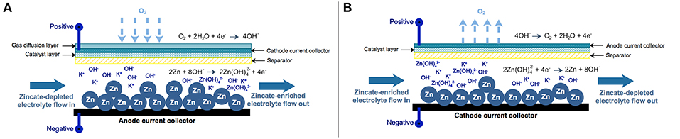
Figure 1. Schematic diagram of zinc-air flow battery and zinc electrolyzer: (A) zinc-air flow battery and (B) zinc electrolyzer.
The Zn electrolyzer, as shown in Figure 1B, consists of a Zn regeneration electrode (negative electrode) and an air electrode (positive electrode). The charge current is supplied to the electrolyzer inducing the reverse reactions of ZAFB to proceed: zincate ions as a reactant are converted back to Zn and hydroxide ions at the negative electrode (a reversion of R1). HER (R3) also significantly affects performance of the electrolyzer because water in the electrolyte can receive electrons directly from the charge current. At the positive electrode, oxygen evolution reaction (OER; a reversion of R5) converts hydroxide ions into oxygen and water.
ZAFB integrated with the Zn electrolyzer can be used as an energy storage system. In Figure 2, the integrated system of ZAFB connecting with Zn electrolyzer is illustrated. The electrolyte circulates between the battery and the electrolyzer. During discharge, ZAFB consumes Zn and produces zincate ion. The effluent from ZAFB, containing a high concentration of zincate ion, is fed into the electrolyzer. The electrolyzer consumes electricity in order to regenerate Zn. Zincate ions are then converted to Zn. In comparison, the effluent from the electrolyzer, containing a lower concentration of zincate ion, is fed into ZAFB. Besides, Zn regenerated from the electrolyzer is mechanically transferred to the ZAFB.
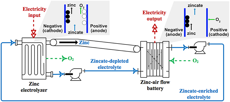
Figure 2. Schematic diagram of zinc-air flow battery integrated with zinc electrolyzer.
Experimental Setup
The model developed in this work was validated against experimental data obtained from a Zn-air flow battery and a Zn electrolyzer. The experimental setup of the battery included a stack arrangement with a Zn anode plate, a separator and an air cathode. The Zn anode consisted of 10 g Zn granules with an average diameter of 0.8 mm loaded inside a 100-mesh stainless steel pouch functioning as a current collector. The area of the current collector was 10 cm2. The separator was prepared by casting 2 g of 24 wt.% poly(vinyl acetate) (PVAc) aqueous solution over both sides of a filter paper and then dried in an oven at 55°C for 10 min. The air cathode plate consisted of three layers: namely, a gas diffusion layer, a cathode current collector and a catalyst layer. Nickel foam (0.5 mm thick with 100 PPI) was employed as the cathode current collector. The gas diffusion layer was fabricated by casting a slurry mixture of 4 g carbon black, 4 g PTFE powder and 2 g glucose in 50 ml ethanol on one side of the nickel foam. The coated nickel foam was then heat-pressed at 350°C for 15 min using a manual hot press machine. Then, the catalyst layer was fabricated on the other side of the nickel foam by adding a slurry mixture of 3 g MnO2 and 7 g carbon black in the binder dissolved solvent. The solvent was prepared by dissolving 1 g poly styrene-co-butadiene (4% butadiene, Sigma Aldrich) as a binder in 50 ml toluene. The catalyst coated cathode was then annealed at 110°C in an oven. The gas diffusion layer exhibited good hydrophobicity. The hydrophobicity of the gas diffusion layer prevents leakage of the electrolyte and water flooding in the cathode. This layer also allows oxygen gas from the atmosphere to permeate through the cell. The active area of the cathode was 10 cm2. KOH aqueous solution (7 M) was used as the electrolyte. The electrolyte with a total volume of 150 mL was fed through the cell at a circulation rate of 50 mL/min using a peristaltic pump.
The experimental setup of the electrolyzer is similar to the battery. The electrolyzer included a stack arrangement with a cathode plate, a separator and an anode. The cathode plate is made of stainless steel with an active area of 10 cm2. The separator was prepared by casting 2 g of 24 wt.% PVAc aqueous solution over both sides of a filter paper and then dried in an oven at 55°C for 10 min. The anode was made of nickel foam (0.5 mm thick with 100 PPI) with an area of 10 cm2.
To validate the mathematical models of ZAFB and Zn electrolyzer, the polarization characteristic of ZAFB was examined. The cell voltage and current were measured by a BA500 battery analyzer using BA500WIN software. The current input can be adjusted manually and cell voltage is measured at the selected current continuously. The data of cell voltage was collected every second. For one current value, the voltage data had been collected for 10 s and 10 voltage values were used to calculate the average cell voltage. After that, the current value was changed to the next value. To measure the overpotential of the electrodes, a mercury/mercury oxide electrode was used as a reference electrode. The overpotential was calculated from the difference of potential between the reference electrode and the equilibrium potential of each electrode.
Mathematical Models
In this section, mathematical models of ZAFB and the Zn electrolyzer are described. The models were developed based on the following assumptions:
• Temperature variations are negligible: an isothermally operation at 298.15 K is assumed. Operation of both ZAFB and the Zn electrolyzer are carried out at room temperature.
• Zero-dimensional space: all variables and parameters inside the cell are independent of the location. The concentration gradient inside the cell is very small and can be neglected. This assumption is valid because the reactions are sufficiently slow; electrode reaction rate is relatively slower than mass transfer rate. Hence, homogenous concentrations in each cell are assumed. In previous literature, a similar assumption was also considered. For instance, Schröder and Krewer (2014) proposed a zero-dimensional zinc-air battery model which was used to investigate the effect of air-composition on cell performance. Dundálek et al. (2017) published a zero-dimensional model of zinc electrodeposition with flowing electrolyte.
• Negligible distance between the cells: the effluent of the electrolyzer immediately affects the ZAFB. In the same manner, the effluent of the ZAFB instantly affects the electrolyzer.
• Constant physical properties, electrode areas and thickness: material properties are assumed to be constant because the state of temperature and pressure is constant. The electrode area and thickness were also assumed to be constant as the cell design.
• Zn oxidation/reduction taking place at the Zn electrode and ORR/OER taking place at the air electrode: no reaction occurred outside the reaction area.
• The capacitive effects are negligible: the system is assumed to be a quasi-electroneutrality condition.
• Ideal gas behavior: ideal gas law is applied as the system is operated at ambient pressure.
• Binary mass diffusion: the diffusion rate is determined by Fick's law.
Species Balances
The molar concentration balance of species k, including OH−, Zn(OH) and H2O, is expressed as in Equation (1). Superscript j represents the electrode or position referring to Zn electrode (j = zinc) and air electrode (j = air):
where Ck is concentration of species k, Velectrolyte is electrolyte volume, Fk is molar flowrate of species k, vk,i is stoichiometric coefficient of species k in reaction i, ri is rate of reaction i (mol/s). Jk is molar transfer rate crossing between Zn and air electrodes of species k including diffusion (diff), migration (mig) and convection (conv) and can be calculated as in Equation (2):
where Dk is diffusivity of species k, εsep is porosity of separator, Asep is area of separator, δsep is thickness of separator, tk is transference number of ion k, is ion number of species k, F is Faraday constant, icell is current density, Fconv is convective volume flow crossing between Zn and air electrodes.
From the zero-dimensional space assumption, the outlet molar flowrate of species k (Fk,out) can be calculated as in Equation (4). The electroneutrality conditions are applied to an ionic species charge balance, as shown in Equation (5):
where SV is space velocity.
The accumulation of ZnO is expressed by the molar balance with reaction R2. Solid Zn is calculated in the same way with reaction R1:
where NZnO is moles of ZnO, NZn is moles of Zn.
Rates of Reactions
The reaction rates of reaction R1, R3 and R5 are modeled by Faradaic reaction approach as expressed in Equations (8–10), respectively:
where rZn, rH, and rair are rates of reaction R1, R3, and R5, respectively. iZn, iH, and iair are current density related to reaction R1, R3, and R5, respectively. ne is number of exchange electrons involved in the reaction.
For ZnO precipitation reaction (Equation R2), the rate of reaction is expressed by a saturation approach (Sunu and Bennion, 1980):
where rZnO is rate of reaction R2, ks is rate constant of reaction R2 and is saturation limit concentration of .
Volume Change
The solid electrode volume change can be expressed as follows:
The electrolyte volume change can be calculated accordingly:
where is specific molar volume of species k, ε is porosity of Zn electrode, is volume of solid Zn electrode, δzinc is thickness of the Zn electrode and AelecZn is surface area of the Zn electrode.
Cell Potential
The cell potential (Ecell) can be calculated from Nernst potential (E0,cell) minus with overpotentials as expressed in Equation (16). The included overpotentials are Zn activation overpotential (), air activation overpotential () and ohmic overpotential (ηohmic):
where Eair is potential of air electrode and Ezinc is potential of the Zn electrode.
where is standard electrode potential of air electrode, is standard electrode potential of the Zn electrode, PO2 is partial pressure of oxygen, Pref is reference state pressure and Cref is reference state concentration.
Activation Loss
The activation loss of Zn electrode () can be calculated from the total current at Zn electrode including Zn dissolution or regeneration (iZn) and HER (iH), as described in Equations (20–25):
where is double layer capacitance of the Zn electrode, is exchange current density of the Zn electrode, is exchange current density of HER, α is charge transfer coefficient, is concentration of zincate ion at the electrode surface, is concentration of zincate ion in the bulk electrolyte and ηH is overpotential of HER at the Zn electrode which can be calculated from Equations (23–25).
where EZH is potential difference between the Zn electrode reaction and HER, EH is electrode potential of HER, is standard electrode potential of HER. The exchange current density () of the Zn electrode can be calculated from Equations (26–29). The reference exchange current density () can be calculated from a correlation between exchange current density and concentration of OH− fitted with experimental data by Dirkse and Hampson (1972) as determined in Equation (26):
where Xzinc is active surface fraction of Zn in solid phase, Vsolid,k is volume of solid species k, as is solid-solution interface area per unit volume, a0 is initial solid-solution interface area per unit volume and ε0 is initial porosity of the Zn electrode. Equation (21) expressed the current of Zn electrode including both oxidation and reduction. For electrolyzer, the term refers to the diffusion limit of zincate ion in Zn reduction reaction (Ito et al., 2012; Dundálek et al., 2017). The concentration of zincate ion at the electrode surface () and bulk electrolyte () can be described as in Equations (30) and (31):
where is diffusivity of zincate ion in electrolyte. The thickness of the zincate ion diffusion layer () can be calculated as in Equations (32–35):
where is the diffusion coefficient of zincate in electrolyte, is concentration of zincate in bulk electrolyte, is the thickness of zincate ion diffusion layer, dh is hydraulic diameter, Sh is Sherwood number, Re is Reynolds number, Sc is Schmidt number, ν is electrolyte velocity, μ is viscosity of electrolyte, and ρelec is density of electrolyte.
The activation loss of air electrode () can be calculated accordingly:
where is double layer capacitance of air electrode, iair is current density respecting to air electrode reaction, CO2, atm is concentration of oxygen in the atmosphere. The exchange current density of air electrode () is expressed as in Equation (38). The oxygen concentration at catalyst surface (CO2, s) can be calculated by using molar concentration balance as described in Equation (39).
where DO2, air is diffusivity of oxygen in air electrode, δGDL is thickness of gas diffusion layer of air electrode, and Aair is active surface area of air electrode.
Ohmic Loss
The ohmic loss (ηohmic) is expressed by Ohmic's law. The total ohmic resistance (Rohmic) is calculated from the conductivity and resistivity of the chemical species and cell components involved. Anode conductivity is accounted for by the solid species conductivity and mole fraction in solid electrode.
where δzinc, δelectrolyte and δair are thickness of the Zn electrode, electrolyte channel and air electrode, respectively. σanode, σelectrolyte and σcathode are conductivity of Zn electrode, electrolyte channel and air electrode, respectively. Rcomp and δcomp are resistivity and equilibrium thickness of other cell components. σZn and σZnO are conductivity of Zn and zinc oxide, respectively.
The developed model was implemented and simulated in MATLAB. The designed parameters and operating conditions are given in Table S1 in Supplementary Material. The initial conditions at t = 0 s are listed in Table S2 in Supplementary Material.
Results and Discussion
Model Validation
As regards validation of the ZAFB and the electrolyzer model, two parameters, including the thickness of the active air electrode (δactive) and the resistance of other cell components (Rcomp), were manually adjusted to fit the model prediction with the experimental data. The fitted values of δactive and Rcomp were 30 μm and 5 Ω. cm, respectively. Figure 3A shows the comparison of the polarization curve between simulation and experimental data of the ZAFB. It was observed that there was good agreement between the model prediction and the experimental data. The comparison of total overpotential of the electrodes between the model prediction and experimental data is displayed in Figure 3B. The overpotential of each electrode is a combination of electrode activation overpotential and the ohmic loss. It was assumed that the ohmic loss from the cathode contributes to half of the total ohmic loss of the cell. The ohmic loss from the anode also contributes to half of the total ohmic loss of the cell. The comparison was acceptable for Zn overpotential. In the case of the air electrode, a small offset was observed. This offset might have arisen from the ohmic loss which arbitrarily adds to the activation overpotential. The measured overpotential of the electrodes from the experiment included some part of the ohmic overpotential which cannot be distinguished from the activation overpotential. The model simulated the activation overpotential and ohmic overpotential separately. Therefore, the measured overpotentials were found to be different from the simulated overpotentials. Furthermore, the differentiation of the air electrode was reported (Schröder et al., 2016). However, this differentiation was not included in the model herein. On the part of the Zn electrolyzer, Figures 3C, D show the comparison of the cell potential and the absolute overpotential of the electrodes between simulation and experiment. Acceptable validity between the simulation and experimental data was observed. A small offset was still shown in the overpotential of air electrode. When charging, it was noted that the growth of oxygen bubbles at the air electrode can affect the behavior of the air electrode (Wang et al., 2015b). Nevertheless, this model does not consider the effects of oxygen bubbles.
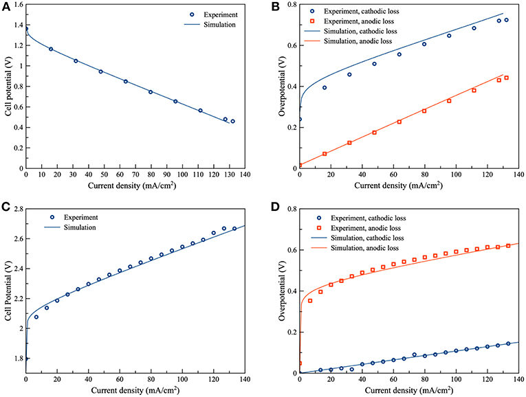
Figure 3. Validation of the proposed models: (A) polarization characteristic of ZAFB (B) anode and cathode overpotential of ZAFB (C) polarization characteristic of Zn electrolyzer and (D) anode and cathode overpotential of Zn electrolyzer.
Battery Performance
The ZAFB with 10 g of initial Zn (0.1538 mole of Zn) was simulated to analyze performance as functions of space velocity, KOH concentration and zincate ion initial concentration. The discharge current density was 100 mA/cm2. The simulation was carried out until depletion of Zn. The performance of ZAFB was evaluated from its current efficiency and discharge energy at the end of the simulation. The current efficiency of ZAFB is defined as the ratio of the total discharge current to the electrochemical equivalent current of the Zn electrode. In this case, the current efficiency was calculated as follows:
and the discharge energy is given by:
where tf is the total operating time in s, NZn,0 is initial mole of Zn and NZn,f is final mole of Zn.
As shown in Figure 4, the current efficiency and discharge energy of ZAFB were examined as functions of KOH concentration and space velocity. Figure 4A shows that the higher KOH concentration provided lower efficiency than the lower KOH concentration. It indicated that corrosion of the Zn electrode increased when the concentration of KOH increased. The corrosion was greater at higher KOH concentration because the reversible potential difference between the Zn electrode reaction and HER (ΔEZH) was negatively larger at higher KOH concentration, as shown in Figure 5. ΔEZH contributes to HER overpotential (ηH) and drives the current of HER, as shown in Equations (22, 23), respectively. The effect of KOH concentration on Zn corrosion was also investigated by other researchers using different methods (Muralidharan and Rajagopalan, 1978; Ravindran and Muralidharan, 1995; El-Sayed et al., 2012). Muralidharan and Rajagopalan (1978) studied corrosion of zinc in sodium hydroxide solution with steady state and transient tafel extrapolation. Ravindran and Muralidharan (1995) determined the hydrogen evolution rate by gasometric method and examined the behavior of zinc in alkaline electrolyte. El-Sayed et al. (2012) proposed the corrosion study of Zn in alkaline solution by tafel plot and electrochemical impedance spectroscopy (EIS). The research as mentioned above is in full agreement with the result concerning the effect of KOH concentration on hydrogen evolution. However, when KOH concentration increased, it had a different effect on the discharge energy, as shown in Figure 4B. Consequently, when concentration of KOH reached about 6 M, it provided maximum exchange current density of Zn dissolution and maximum ionic conductivity. Using KOH concentration more or <6 M decreased the energy discharge of ZAFB. Thus, at 6 M KOH concentration, the maximum performance for ZAFB was achieved.
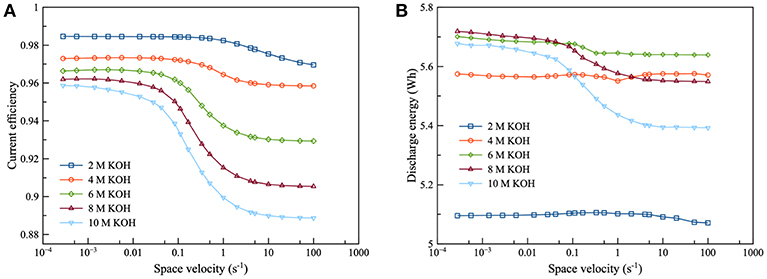
Figure 4. Effects of KOH concentration on ZAFB using zincate ion initial concentration 0.2 M and discharge current density of 100 mA/cm2: (A) current efficiency as a function of space velocity and (B) discharge energy as a function of space velocity.
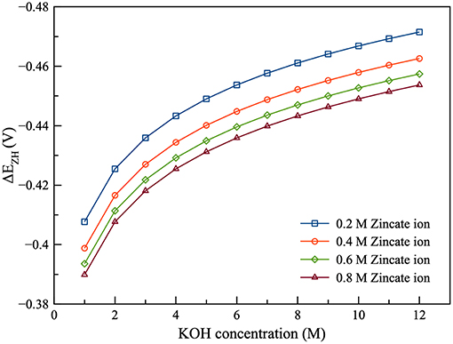
Figure 5. Effects of zincate ion initial concentration on ΔEZH as a function of KOH concentration.
As regards the effect of flowrate, the increasing space velocity of the electrolyte provided lower current efficiency because the higher electrolyte flowrate maintained a higher concentration of KOH which contributed to higher corrosion. However, the flowrate exhibited less effect at lower KOH concentration.
Figure 6 presents the effect of zincate ion concentration on the performance of ZAFB. The results showed that increasing the concentration of zincate ion tended to increase the current efficiency and discharge energy of the battery. This was because hydrogen evolution was affected by the zincate ion concentration. Previously, Figure 5 shows the relation between ΔEZH and concentration of zincate ion. When zincate ion concentration increased, ΔEZH reduced due to the decrease in the reversible Zn electrode potential (Ezinc). According to the previous work of Shivkumar et al. (1995), it was reported that adding ZnO reduced hydrogen evolution and Zn dissolution. The previous work came to the same conclusion as the result herein.
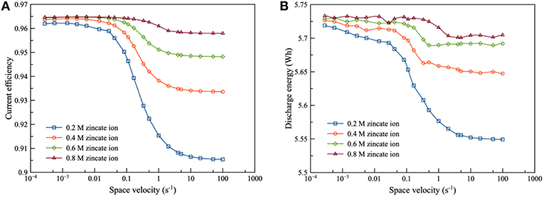
Figure 6. Effects of zincate ion initial concentration on ZAFB using 8 M KOH at discharge current density of 100 mA/cm2: (A) current efficiency as a function of space velocity and (B) discharge energy as a function of space velocity.
Electrolyzer Performance
In the case of the electrolyzer, simulation was performed in order to examine the effects of space velocity, KOH concentration and zincate ion concentration using a charge current density of 100 mA/cm2. The target amount of regenerated Zn was 10 g. The simulation was terminated when it reached the target amount of Zn. The current efficiency of the electrolyzer is the ratio of the equivalent current for Zn regeneration to the total applied current. The current efficiency and charge energy of electrolyzer is expressed by:
The performance of the Zn electrolyzer was evaluated by the current efficiency and the charge energy, as shown in Figure 7. It was found that the flow of the electrolyte had a significant effect on the performance of the electrolyzer. Increasing space velocity increased the current efficiency but decreased charge energy. The high flowrate was preferred because increasing flowrate reduced the diffusion film thickness of the zincate ion. Consequently, Zn reduction was promoted and HER was suppressed. As regards the effect of zincate ion concentration, current efficiency increased and charge energy decreased when the concentration of zincate ion increased. The higher zincate ion concentration provided greater driving force of the diffusion and thereby enhanced the Zn reduction reaction. Increasing zincate ion concentration also reduced ΔEZH of HER which also suppressed the corrosion of Zn electrode. Many previous works have reached the same conclusion about the effect of zincate ion on Zn electrodeposition, as the result put forward herein (Einerhand et al., 1988; Sharifi et al., 2009; Dundálek et al., 2017). Einerhand et al. (1988) reported that the high concentration of zincate ion promoted ZnO layer formation on Zn electrode surface which protected Zn against corrosion. Dundálek et al. (2017) also highlighted the relation between Zn deposition morphology, electrolyte condition and HER and concluded that high flowrate and zincate ion concentration were preferred for Zn electrodepositon with low HER.
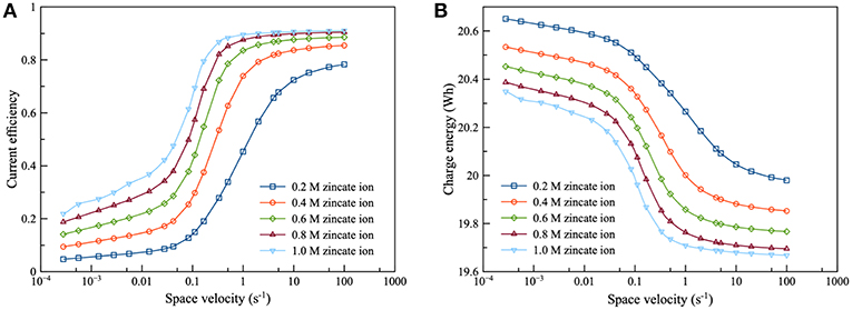
Figure 7. Effects of zincate ion initial concentration on zinc electrolyzer using 8 M KOH at charge current density of 100 mA/cm2: (A) current efficiency as a function of space velocity and (B) charge energy as a function of space velocity.
Regarding the effect of KOH concentration, as illustrated in Figure 8, it was observed that KOH concentration had a complicated effect on current efficiency and charge energy. KOH concentration had a connection with the saturation limit of zincate ion. When zincate ion was not saturated, KOH concentration had little effect on current efficiency in the low flowrate region. However, a different trend was observed in the high flowrate region (space velocity above 1 per second). In the high flowrate region, increasing KOH concentration provided lower current efficiency due to increasing ΔEZH. As for the effect on charge energy, the higher KOH concentration needed higher charge energy because of the higher Nernst potential (E0,cell). Sharifi et al. (2009) also studied zinc electrolysis using various KOH concentration and approached to the same conclusion. When the zincate ion was saturated, the effect on current efficiency and charge energy was different from that of non-saturated zincate ion. KOH concentration had less effect in the high flowrate region, but it had a direct effect in the low flowrate region. When KOH concentration increased, efficiency tended to increase due to the saturation limit of zincate ion. The saturation limit increased due to the increase in KOH concentration. The effect of the saturation limit showed a similar trend with the effect of zincate ion concentration, as in Figure 7. The higher saturation limit provided higher efficiency.
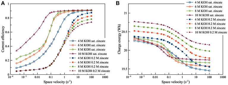
Figure 8. Effects of KOH concentration using different zincate ion initial concentration [0.2 M (dotted line) and saturated zincate ion (solid line)] at discharge current density of 100 mA/cm2: (A) current efficiency as a function of space velocity and (B) charge energy as a function of space velocity.
Integrated System
The operation having an equal charge-discharge current density of 100 mA/cm2 was simulated. The initial Zn in ZAFB was 10 g (0.1538 mole of Zn). Zn depletion in ZAFB was the termination criterion. The current efficiency of the integrated system is defined as the ratio of the total amount of Zn regenerated to the total amount of Zn utilized, as in Equation (47). The other performance evaluation is energy efficiency which is expressed as the ratio of discharge energy to charge energy, as described in Equation (48):
Then, the performance of the integrated system was examined by considering various operating parameters i.e., space velocity, KOH concentration and zincate ion concentration.
The current efficiency and energy efficiency of the integrated system are as shown in Figure 9. It was observed that the efficiency trends of the integrated system were comparable with the charge efficiency trends of the electrolyzer, as illustrated in Figures 9A–C. It can be inferred that the efficiency of the integrated system is dominated by the electrolyzer. The results showed that increasing flowrate enhanced the current efficiency except at low zincate ion concentration. At low zincate concentration, the inflection point occurred at space velocity range 0.1–1 s−1 and especially at 0.2 M zincate concentration. The condition at the bottom of the curve is the condition such that the total amount of zincate ion transferring to the electrode surface is minimum compared to the adjacent condition. The increasing flowrate had a positive effect on the energy efficiency of the system. In the case of the comparison of effect of zincate ion concentration, the higher zincate ion concentration provided better performance throughout the range of space velocity. Increasing zincate ion concentration was able to suppress HER and increase the current efficiency for both discharging and charging. At space velocity, approximately below 0.1 s−1, increasing zincate ion concentration improved energy efficiency. In contrast, at space velocity above 1 s−1, increasing zincate ion concentration provided an adverse effect on energy efficiency.
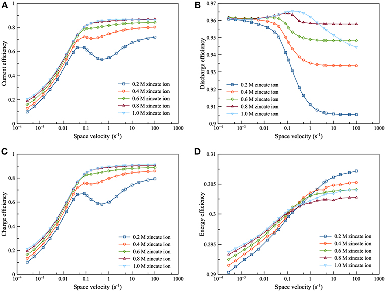
Figure 9. Effects of zincate ion initial concentration using 8 M KOH at charge and discharge current density of 100 mA/cm2: (A) current efficiency as a function of space velocity (B) discharge efficiency as a function of space velocity (C) charge efficiency as a function of space velocity and (D) energy efficiency as a function of space velocity.
In Figure 10, the performance of the integrated system was examined: namely, from 2 to 10 M KOH concentration. It was observed that the efficiency curve could be divided into 2 regions: the region before and after the inflection point. For the region before the inflection point, efficiency increased as KOH concentration increased. Zincate ion was saturated herein. Subsequently, when KOH concentration increased, the saturation limit of zincate ion increased. Therefore, zincate ion diffusion also improved. On the other hand, efficiency decreased as KOH concentration increased for the region after the inflection point. Zincate ion was not saturated in this region. Thus, the concentration of zincate ion was not much different between the various KOH concentration. However, HER still intensified as KOH concentration increased. It is evident that 8 M KOH concentration provided maximum energy efficiency. This was followed by 6 M KOH concentration. Energy efficiency was dominated by the performance of the discharge process which was influenced mainly by optimal KOH concentration. As mentioned previously in the section of battery performance, concentration of about 6 to 7 M KOH provided maximum exchange current density of the Zn electrode reaction and maximum ionic conductivity. Consequently, in the case of the integrated system, 6 and 8 M KOH concentration exhibited optimal performance.
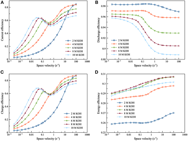
Figure 10. Effects of KOH concentration using 0.2 M zincate ion initial concentration at charge and discharge current density of 100 mA/cm2: (A) current efficiency as a function of space velocity (B) discharge efficiency as a function of space velocity (C) charge efficiency as a function of space velocity and (D) energy efficiency as a function of space velocity.
Conclusion
In this work, a mathematical model of a Zn-air flow battery integrated with a Zn electrolyzer including the model of HER was developed to evaluate the system performance. Thereby, the following parameters were investigated: electrolyte flowrate, potassium hydroxide (KOH) concentration and zincate ion initial concentration. Besides, the influence of the hydrogen evolution reaction (HER) on the performance of the Zn-air energy storage system was examined. Upon investigation, it was found that KOH concentration had a significant effect on the performance of the battery. Further, it was noted that increasing KOH concentration enhanced HER and reduced the current efficiency. However, the optimal KOH concentration, which was about 6–7 M, provided maximum discharge energy. Increasing zincate ion initial concentration was able to suppress the HER and increase the current efficiency of the battery because of the lessening of reversible potential difference between the Zn electrode reaction and HER. As regards the electrolyzer, the results showed that the performance of the electrolyzer was dominated by zincate ion initial concentration and electrolyte flowrate. When zincate ion initial concentration increased together with the flowrate, current efficiency significantly increased. Further, the charge energy was reduced due to the enhancement of zincate ion diffusion to the electrode surface. Yet, increasing KOH concentration did not directly improve electrolyzer performance but contributed to the increment of saturation limit of zincate ion which enhanced the electrolyzer performance. For the overall integrated system, it was observed that the current efficiency of the integrated system was dominated by the electrolyzer. Therefore, increasing zincate ion initial concentration and electrolyte flowrate had a beneficial effect on the current efficiency of the integrated system. On the other hand, the energy efficiency of the integrated system was essentially influenced by the discharging cell. Maximum energy efficiency was obtained by the optimal concentration of KOH similar to the discharge energy of the flow battery. The results of this work described the role that HER contributed toward the performance of the integrated system of Zn-air flow battery and Zn electrolyzer. Overall, it was found that HER had a detrimental effect on the performance of the integrated system. To conclude, it can be seen that control of the operating conditions was found to be an effective way to diminish HER and extract optimal performance out of the integrated system.
Author Contributions
SK conceived the research project. WL conducted the experiments and performed the simulation. KB conducted the experiments during revision process. Data analyses were done by WL with consultation with SK. The paper was written by WL and SK, and all authors contributed to the subsequent drafts. All authors reviewed the manuscript.
Funding
The research is supported by Chulalongkorn Academic Advancement into its Second Century Project, Chulalongkorn University. WL thanks the Chulalongkorn University Dusadeepipat scholarship.
Conflict of Interest Statement
The authors declare that the research was conducted in the absence of any commercial or financial relationships that could be construed as a potential conflict of interest.
Acknowledgments
All authors thanks the support from Thailand's Office of Higher Education, Chulalongkorn University, and Government of France/Campus France under Franco-Thai Cooperation Programme in Higher Education and Research/Franco-Thai Mobility Programme/PHC SIAM. Besides, the authors would like to thank Mr. Kijchai Kanjanapaparkul for his dedicated help in the batteries fabrication.
Supplementary Material
The Supplementary Material for this article can be found online at: https://www.frontiersin.org/articles/10.3389/fenrg.2019.00015/full#supplementary-material
References
Amunátegui, B., Ibáñez, A., Sierra, M., and Pérez, M. (2018). Electrochemical energy storage for renewable energy integration: zinc-air flow batteries. J. Appl. Electrochem. 48, 627–637. doi: 10.1007/s10800-017-1133-7
Bockelmann, M., Kunz, U., and Turek, T. (2016). Electrically rechargeable zinc-oxygen flow battery with high power density. Electrochem. Comm. 69, 24–27. doi: 10.1016/j.elecom.2016.05.013
Deiss, E., Holzer, F., and Haas, O. (2002). Modeling of an electrically rechargeable alkaline Zn–air battery. Electrochim. Acta. 47, 3995–4010. doi: 10.1016/S0013-4686(02)00316-X
Dirkse, T. P., and Hampson, N. A. (1972). The Zn(II)/Zn exchange reaction in KOH solution—I. exchange current density measurements using the galvanostatic method. Electrochim. Acta. 17, 135–141. doi: 10.1016/0013-4686(72)85014-X
Dundálek, J., Šnajdr, I., Libánský, O., Vrána, J., Pocedič, J., Mazúr, P., et al. (2017). Zinc electrodeposition from flowing alkaline zincate solutions: role of hydrogen evolution reaction. J. Power Sour. 372, 221–226. doi: 10.1016/j.jpowsour.2017.10.077
Dunn, B., Kamath, H., and Tarascon, J.-M. (2011). Electrical energy storage for the grid: a battery of choices. Science 334, 928–935. doi: 10.1126/science.1212741
Einerhand, R. E. F., Visscher, W. H. M., and Barendrecht, E. (1988). Hydrogen production during zinc deposition from alkaline zincate solutions. J. Appl. Electrochem. 18, 799–806. doi: 10.1007/BF01016034
El-Sayed, A.-R., Mohran, H. S., and Abd El-Lateef, H. M. J. M. (2012). Corrosion study of zinc, nickel, and zinc-nickel alloys in alkaline solutions by tafel plot and impedance techniques. Metallurg. Mater. Trans. A 43, 619–632. doi: 10.1007/s11661-011-0908-4
Escalante Soberanis, M. A., Mithrush, T., Bassam, A., and Mérida, W. (2018). A sensitivity analysis to determine technical and economic feasibility of energy storage systems implementation: a flow battery case study. Renew. Energy 115, 547–557. doi: 10.1016/j.renene.2017.08.082
Fu, J., Zhang, J., Song, X., Zarrin, H., Tian, X., Qiao, J., et al. (2016). A flexible solid-state electrolyte for wide-scale integration of rechargeable zinc–air batteries. Energy Environ. Sci. 9, 663–670. doi: 10.1039/C5EE03404C
Garcia, G., Ventosa, E., and Schuhmann, W. (2017). Complete prevention of dendrite formation in Zn metal anodes by means of pulsed charging protocols. Appl. Mater. Interfaces 9, 18691–18698. doi: 10.1021/acsami.7b01705
Gavrilović-Wohlmuther, A., Laskos, A., Zelger, C., Gollas, B., and Whitehead, A. H. (2015). Effects of electrolyte concentration, temperature, flow velocity and current density on Zn deposit morphology. J. Energy Power Eng. 9, 1019–28. doi: 10.17265/1934-8975/2015.11.010
Hosseini, S., Lao-atiman, W., Han, S. J., Arpornwichanop, A., Yonezawa, T., and Kheawhom, S. (2018). Discharge performance of zinc-air flow batteries under the effects of sodium dodecyl sulfate and pluronic F-127. Sci. Rep. 8:14909. doi: 10.1038/s41598-018-32806-3
Ito, Y., Wei, X., Desai, D., Steingart, D., and Banerjee, S. (2012). An indicator of zinc morphology transition in flowing alkaline electrolyte. J. Power Sour. 211, 119–128. doi: 10.1016/j.jpowsour.2012.03.056
Jing, F., Paul, C. Z., Gyu, P. M., Aiping, Y., Michael, F., and Zhongwei, C. (2017). Electrically rechargeable zinc–air batteries: progress, challenges, and perspectives. Adv. Mater. 29:1604685. doi: 10.1002/adma.201604685
Lao-atiman, W., Julaphatachote, T., Boonmongkolras, P., and Kheawhom, S. (2017). Printed transparent thin film Zn-MnO2 battery. J. Electrochem. Soc. 164:A859–A863. doi: 10.1149/2.1511704jes
Lee, C. W., Sathiyanarayanan, K., Eom, S. W., Kim, H. S., and Yun, M. S. (2006). Effect of additives on the electrochemical behaviour of zinc anodes for zinc/air fuel cells. J. Power Sour. 160, 161–164. doi: 10.1016/j.jpowsour.2006.01.070
Li, Y., and Dai, H. (2014). Recent advances in zinc-air batteries. Chem. Soc. Rev. 43, 5257–5275. doi: 10.1039/C4CS00015C
Li, Y., Gong, M., Liang, Y., Feng, J., Kim, J.-E., Wang, H., et al. (2013). Advanced zinc-air batteries based on high-performance hybrid electrocatalysts. Nat. Comm. 4:1805. doi: 10.1038/ncomms2812
Mainar, A. R., Iruin, E., Colmenares, L. C., Kvasha, A., de Meatza, I., Bengoechea, M., et al. (2018). An overview of progress in electrolytes for secondary zinc-air batteries and other storage systems based on zinc. J. Energy Storage 15, 304–328. doi: 10.1016/j.est.2017.12.004
Mao, Z., and White, R. E. (1992). Mathematical modeling of a primary zinc/air battery. J. Electrochem. Soc. 139, 1105–1113. doi: 10.1149/1.2069348
Muralidharan, V. S., and Rajagopalan, K. S. (1978). Kinetics and mechanism of corrosion of zinc in sodium hydroxide solutions by steady-state and transient methods. J. Electroanalyt. Chem. Interfacial Electrochem. 94, 21–36. doi: 10.1016/S0022-0728(78)80395-7
Park, J., Park, M., Nam, G., Lee, J.-S., and Cho, J. (2015). All-solid-state cable-type flexible zinc–air battery. Adv. Mater. 27, 1396–1401. doi: 10.1002/adma.201404639
Pei, P., Wang, K., and Ma, Z. (2014). Technologies for extending zinc–air battery's cyclelife: a review. Appl. Energy 128, 315–324. doi: 10.1016/j.apenergy.2014.04.095
Ravindran, V., and Muralidharan, V. S. (1995). Cathodic processes on zinc in alkaline zincate solutions. J. Power Sour. 55, 237–241. doi: 10.1016/0378-7753(95)02184-I
Saleh, M. M., Weidner, J. W., El-Anadouli, B. E., and Ateya, B. G. (1997). Electrowinning of nonnoble metals with simultaneous hydrogen evolution at flow-through porous electrodes: III. time effects. J. Electrochem. Soc. 144, 922–927. doi: 10.1149/1.1837508
Savaskan, G., Huh, T., and Evans, J. W. (1992). Further studies of a zinc-air cell employing a packed bed anode part I: discharge. J. Appl. Electrochem. 22, 909–915. doi: 10.1007/BF01024138
Schröder, D., and Krewer, U. (2014). Model based quantification of air-composition impact on secondary zinc air batteries. Electrochim. Acta. 117, 541–553. doi: 10.1016/j.electacta.2013.11.116
Schröder, D., Laue, V., and Krewer, U. (2016). Numerical simulation of gas-diffusion-electrodes with moving gas–liquid interface: a study on pulse-current operation and electrode flooding. Comput. Chem. Eng. 84, 217–225. doi: 10.1016/j.compchemeng.2015.09.005
Sharifi, B., Mojtahedi, M., Goodarzi, M., and Vahdati Khaki, J. (2009). Effect of alkaline electrolysis conditions on current efficiency and morphology of zinc powder. Hydrometallurgy 99, 72–76. doi: 10.1016/j.hydromet.2009.07.003
Shivkumar, R., Paruthimal Kalaignan, G., and Vasudevan, T. (1995). Effect of additives on zinc electrodes in alkaline battery systems. J. Power Sour. 55, 53–62. doi: 10.1016/0378-7753(94)02170-8
Simičić, M. V., Popov, K. I., and Krstajić, N. V. (2000). An experimental study of zinc morphology in alkaline electrolyte at low direct and pulsating overpotentials. J. Electroanalyt. Chem. 484, 18–23. doi: 10.1016/S0022-0728(00)00035-8
Smedley, S. I., and Zhang, X. G. (2007). A regenerative zinc–air fuel cell. J. Power Sour. 165, 897–904. doi: 10.1016/j.jpowsour.2006.11.076
Sunu, W. G., and Bennion, D. N. (1980). Transient and failure analyses of the porous zinc electrode: i theoretical. J. Electrochem. Soc. 127, 2007–2016. doi: 10.1149/1.2130054
Suren, S., and Kheawhom, S. (2016). Development of a high energy density flexible zinc-air battery. J. Electrochem. Soc. 163, A846–A850. doi: 10.1149/2.0361606jes
Wang, K., Pei, P., Ma, Z., Chen, H., Xu, H., Chen, D., et al. (2015a). Dendrite growth in the recharging process of zinc-air batteries. J. Mater. Chem. A 3, 22648–22655. doi: 10.1039/C5TA06366C
Wang, K., Pei, P., Ma, Z., Chen, H., Xu, H., Chen, D., et al. (2015b). Growth of oxygen bubbles during recharge process in zinc-air battery. J. Power Sour. 296, 40–45. doi: 10.1016/j.jpowsour.2015.07.039
Wang, K., Pei, P., Wang, Y., Liao, C., Wang, W., and Huang, S. (2018). Advanced rechargeable zinc-air battery with parameter optimization. Appl. Energy 225, 848–856. doi: 10.1016/j.apenergy.2018.05.071
Wang, Z., Meng, X., Wu, Z., and Mitra, S. (2017). Development of flexible zinc–air battery with nanocomposite electrodes and a novel separator. J. Energy Chem. 26, 129–138. doi: 10.1016/j.jechem.2016.08.007
Wongrujipairoj, K., Poolnapol, L., Arpornwichanop, A., Suren, S., and Kheawhom, S. (2017). Suppression of zinc anode corrosion for printed flexible zinc-air battery. Phys. Status Solidi B 254:1600442. doi: 10.1002/pssb.201600442
Xu, M., Ivey, D. G., Xie, Z., and Qu, W. (2015). Rechargeble Zn-air batteries: progress in electrolyte development and cell configuration advancement. J. Power Sour. 283, 358–371. doi: 10.1016/j.jpowsour.2015.02.114
Zhang, S. (2013). Status, opportunities, and challenges of electrochemical energy storage. Front. Energy Res. 1:8. doi: 10.3389/fenrg.2013.00008
Zhu, A. L., Wilkinson, D. P., Zhang, X., Xing, Y., Rozhin, A. G., and Kulinich, S. A. (2016). Zinc regeneration in rechargeable zinc-air fuel cells—a review. J. Energy Storage 8, 35–50. doi: 10.1016/j.est.2016.09.007
Nomenclature
a0 Initial solid-solution interface area per unit volume, dm2/dm3.
ac Specific surface area of catalyst per unit volume, dm2/dm3.
as Solid-solution interface area per unit volume, dm2/dm3.
Azinc Active surface area of Zn electrode, dm2.
Aair Active surface area of air electrode, dm2.
Asep Area of separator, dm2.
Cref Reference state concentration, mol/dm3.
Double layer capacitance of Zn electrode, F/dm2.
Double layer capacitance of air electrode, F/dm2.
Concentration of specie k at electrode j, mol/cm3.
Dk Diffusivity/diffusion coefficient of specie k, dm2/s.
E0,cell NERNST potential/standard electrode potential, V.
Ecell Cell voltage, V.
Ezinc Reversible potential of Zn electrode, V.
Eair Reversible potential of air electrode, V.
EH Reversible potential of hydrogen evolution reaction, V.
F Faraday constant, C/mol.
Fconv Convective volume flow, dm3/s.
Fk,in Inlet molar flowrate of specie k, mol/s.
Fk,out Outlet molar flowrate of specie k, mol/s.
I Electrical current, A.
icell Current density, A/dm2.
i0 Exchange current density, A/dm2.
Reference exchange current density, A/dm2.
Jk Molar transfer rate between electrodes, mol/s.
Convective molar flow rate, mol/s.
Diffusion molar flow rate, mol/s.
Migration molar flow rate, mol/s.
ks Rate constant of ZnO precipitation reaction, dm3/s.
ne Number of exchange electron involved in the reaction.
Moles of specie k at electrode j, mol.
Pref Reference pressure, atm.
PO2 Partial pressure of oxygen, atm.
ri Rate of reaction i, mol/s.
R Gas constant, J/mol · K.
Rcomp Resistivity of cell component, Ω · dm.
Rohmic Total ohmic resistance, Ω.
SV Space velocity, s−1.
t Time, s.
tk Transference number of ion k.
T Temperature, K.
Volume of electrolyte at electrode j, dm3.
Volume of solid Zn electrode, dm3.
Vsolid,k Volume of solid specie k, dm3.
Specific molar volume of specie k, dm3/mol.
Xzinc Active surface fraction of Zn in solid phase.
Ion number of specie k
Greek symbol
α Charge transfer coefficient.
δair Thickness of air electrode, dm.
δelectrolyte Thickness of electrolyte, dm.
δzinc Thickness of Zn electrode, dm.
δactive Thickness of active reaction zone, dm.
δsep Thickness of separator, dm.
δGDL Thickness of gas diffusion layer, dm.
ΔEZH Potential difference between Zn and hydrogen electrode, V.
ε Porosity of Zn electrode.
ε0 Initial porosity of Zn electrode.
εsep Porosity of separator.
Activation loss/activation overpotential of Zn electrode, V.
Activation loss/activation overpotential of air electrode, V.
Ionic separator loss, V.
ηohmic Ohmic loss/ohmic overpotential, V.
σanode Total conductivity of anode, S/dm.
σcathode Total conductivity of cathode, S/dm.
σk Conductivity of specie k, S/dm.
σelectrolyte Conductivity of electrolyte, S/dm.
υk,i Stoichiometric coefficient of specie k in reaction i.
Keywords: zinc-air battery, zinc electrolyzer, simulation, energy storage, flow battery
Citation: Lao-atiman W, Bumroongsil K, Arpornwichanop A, Bumroongsakulsawat P, Olaru S and Kheawhom S (2019) Model-Based Analysis of an Integrated Zinc-Air Flow Battery/Zinc Electrolyzer System. Front. Energy Res. 7:15. doi: 10.3389/fenrg.2019.00015
Received: 17 November 2018; Accepted: 05 February 2019;
Published: 22 February 2019.
Edited by:
Hua Kun Liu, University of Wollongong, AustraliaReviewed by:
Liqiang Mai, Wuhan University of Technology, ChinaAhmad Azmin Mohamad, School of Materials & Mineral Resources Engineering, University of Science, Malaysia
Copyright © 2019 Lao-atiman, Bumroongsil, Arpornwichanop, Bumroongsakulsawat, Olaru and Kheawhom. This is an open-access article distributed under the terms of the Creative Commons Attribution License (CC BY). The use, distribution or reproduction in other forums is permitted, provided the original author(s) and the copyright owner(s) are credited and that the original publication in this journal is cited, in accordance with accepted academic practice. No use, distribution or reproduction is permitted which does not comply with these terms.
*Correspondence: Soorathep Kheawhom, soorathep.k@chula.ac.th