Design and Implement of Staggered Parallel Lithium Battery Equalization Converter With Jumper Switches
 Xueqi Wang
 Linlu Huang1
 - 1College of Electrical and New Energy, China Three Gorges University, Yichang, China
- 2College of Computer and Information Technology, China Three Gorges University, Yichang, China
To mitigate the pressure on energy storage and enhance the flexibility of the power system, lithium-ion batteries are widely utilized in large-scale energy storage in smart grids due to their superior charging and discharging performance and energy storage characteristics. Whereas the inconsistency of lithium battery cells has become a key issue that limits the overall performance of the battery pack. A novel flexible equalization converter is proposed to handle this issue. This converter is combined with a staggered parallel topology and jumper switched, which enables an energy transfer path to exist between any cell to the rest pack and any substring to the rest substring. The electromagnetic transient model and its small-signal model of the proposed converter have been developed in MATLAB to prove its effectiveness. Finally, the conclusion could be arrived at that the proposed topology shows a better performance compared to the traditional method.
1 Introduction
The gradual establishment and realization of the global energy Internet put forward higher requirements for the sustainable supply management and deployment of future electric energy, in which the large-scale energy storage technology is the cornerstone and plays a vitally important role in the modern industry (Wei et al., 2019a). As a reliable energy storage device, lithium-ion batteries are widely utilized in scenarios such as new energy vehicles and energy storage power stations due to their high energy density and cyclable characteristics (Song et al., 2017; Lin et al., 2018).
Normally, an independent battery needs to be connected in series or paralleled into groups to output the required power in industrial applications due to its electrochemical limitations. However, individual batteries are subject to certain inconsistencies due to the manufacturing process and operating environment factors (Dai et al., 2021). This inconsistency gradually accumulates, thereby increasing the gap in individual recyclable capacity and reducing the overall performance of the battery packs. Once this issue is ignored, it will probably lead to serious safety accidents such as spontaneous combustion or even explosion, especially during the charging and discharging process. The energy inconsistency of lithium batteries is shown in Figure 1.
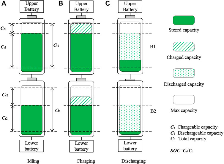
FIGURE 1. The recyclable capacity of series batteries.
To alleviate the inconsistency of individual lithium batteries and prolong the life of battery packs, researchers have proposed a variety of equalization topologies to fulfill the energy balance and improve the recyclable capacity in the battery packs. According to the path of energy flow, these converters can be divided into three dominant types: cell to cell (Shang et al., 2015; Shang et al., 2017a; Shang et al., 2018; Liu et al., 2020), cell to pack (CP) (Wang et al., 2015; Shang et al., 2017b), and pack to pack (PP) (Shang et al., 2017b). Bypass topology is one traditional cell-to-cell method, in which the power of overcharged cells will be transferred between any cell-to-any cell method in reference (Shang et al., 2015; Shang et al., 2017a; Shang et al., 2018), which makes it feasible for any overcharged power to be directly delivered to the specific cell. Switched capacitor and coupled inductors are introduced on the basis the buck-boost circuit, so that energy can be transferred from any battery to any battery (Liu et al., 2020). The system is highly flexible and easy to expand, but because of its passive devices, the control complexity of the system has not increased. Compared with this step-by-step method, the cell-to-pack solution proposed in reference (Wang et al., 2015; Shang et al., 2017b) is relatively more time-saving in the dominant situation. Most of the cell-to-pack topologies utilize a center transformer to temporarily store energy from overcharged one and then release it to the whole pack. The dominant demerit of this method lies in the heavy volume and weight. Besides, the energy contributed by the overcharged battery will be recharged, subsequently leading to extra power loss that could have been avoided. In reference (Xiaolin et al., 2018), a novel tapped inductor balancing circuit that allows any ratio of voltage balancing for hybrid energy storage cells is proposed. Different from the buck-boost converter and switched capacitor, the tapped inductor has advantages in step-free adjustment and is suitable for balancing hybrid source packages composed of batteries and aged batteries. Besides, the part of the energy loss of the equalizing circuit during operation will be converted into heat dissipation, which will help improve the battery pack’s ability to operate in a low-temperature environment. An integrated battery self-heater is proposed in reference (Zhu et al., 2021), which enables an effective preheat on automotive batteries.
The pioneering concept of balancing current ratio is discussed, which reflects the ratio of the average balancing current to the average pack current (Tang et al., 2021). Introducing the concept of balancing current ratio can more effectively observe the state of health of the battery, to achieve a more accurate state-of-charge (SOC) balance. Another converter with multiple balancing modes is proposed in reference (Wang et al., 2020), which means flexible equalization paths and different equalization processes can occur simultaneously to shorten equalization time.
Another flexible interleaved converter proposed in reference (Mestrallet et al., 2014) utilizes a bidirectional DC equalizer instead of the transformer to reduce the size and weight of the system in which each phase of interleaved converter could synchronously operate. The current of natural active balancing is low leading to a little time-consuming at the end of equalization. Yewen Wei et al. proposed a hybrid forced and natural method in reference (Wei et al., 2018) that could relatively reduce the time of the equalization process. Then, the matrix solution of the working time of the equalizer switch array can directly obtain the switch control scheme in the independent equalizer, avoiding the energy circulation caused by the repeated conduction of the same group of switches in the independent converter (Wei et al., 2019b). To reduce the control complexity of inductor equalizers, a bidirectional multi-input and multi-output energy equalization circuit on the basis of the game theory is proposed in reference (Wang et al., 2019). Finally, a systematic analysis method is proposed to evaluate the performance of various converters (Shan et al., 2020).
Despite the energy inconsistency of series-connected lithium battery packs, researchers have proposed a richer converter topology and control method for achieving the energy balance of the battery pack. However, as the number of battery cells in series increases, the complexity of balancing has also increased, and the balancing method under a single mode is normally hard to satisfy the significantly growing requirements. Hence, a staggered parallel equalization converter with jumper switches is proposed to handle the above issue in this paper. Compared to previous research, our contributions are listed as follows:
1) A novel topology is proposed to mitigate the inconsistency of the batteries in which each phase of this converter could synchronously operate to obtain fast equalization;
2) Two operation modes have been implemented to handle various conditions. In CP mode, the energy from any overcharged cell could be directly delivered to the rest of the battery pack. In PP mode, the extra energy could be relocated between the two subpack with only one switch.
3) The small-signal model (SSM) of the converter is derived in detail, which will provide sufficient guidance for designing control parameters.
4) The simulation and comparisons on performance among CP mode, PP mode, and the hybrid modes are provided.
The rest of the paper is organized as follows. In Section 2, the equalization system structure and principles are given and analyzed. Subsequently, the small signal of the proposed converter has been provided in Sections 3. Then, the simulation on the electromagnetic transient model and the experiment is demonstrated and the comparison is given as well in Section 4. Finally, the conclusions and some potential future works are presented in Section 5.
Design and Operating Principle
Structure of the Proposed Converter
The equalization system with an interleaved converter on the basis of game theory has been analyzed in reference (Peng et al., 2021). This topology allows transferring high-energy quantities from any overcharged cell(s) to any undercharged cell(s) without using transformers. This can be done under any operating conditions applied to the stack, charging or discharging, high or low power rates, due to the parallel equalizers of the topology. The dominant demerit of this design is that, when a battery is overcharged, a certain switch combination is probably required to transfer the energy of this abnormal battery to all the other batteries in the pack, which leads to a lot of power loss.
To actualize the energy transfer between any overcharged battery and the remaining batteries in the battery pack, jumper switches are proposed and implemented to the interleaved converter. The jumper switches are connected to adjacent inductors that make it available to deliver the energy from any overcharged cell to the rest cells in the string without any other component. The conventional and proposed topologies are shown in Figure 2. A detailed description and analysis of the operation mode could be found in the following sections.
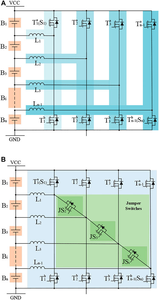
FIGURE 2. Structure of the converter. (A) Conventional topology. (B) Proposed topology.
In Figure 2A, the conventional topology only has a PP working mode. The battery pack is divided into two parts for the energy exchange. In Figure 2B, the proposed topology is equipped with jumper switches that enable additional energy paths, named cell-to-pack working mode. With parallel jumper switches, the abnormal battery is used as a single unit to exchange energy to two adjacent battery packs.
Working Principle on Pack-to-Pack (PP) Mode
Initially, assuming that the upper i batteries in the series are overcharged, their energy needs to be transferred to the lower i + 1 to n batteries in the pack. To illustrate this process more clearly, one of the phase sub-modules of the converter is selected for thorough description and simplified analysis. More specifically, the inductor L absorbs the power of the upper i batteries when the switch Ta i is on (stage I); and, then, the switch is off, the inductor releases its power to the lower i + 1 to n batteries (stage II). Similarly, when the upper i batteries are over-discharged, the energy flow can be reversed as well. The detailed process and analysis of this mode can be found in Figure 3 and below context.
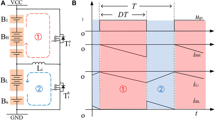
FIGURE 3. The foundational working principle of PP mode. (A) Modular and power flow. (B) Key waveforms.
In Table 1, the conditions of each component are presented. Therefore, the mathematical formula in a switching cycle could be derived as follows.
1) When the switch Tia is on (0 < t < DT), the current flowing through the inductor Li will rise linearly; at this time, the front i battery charges the inductor Li, and the inductor Li stores energy;
2) When the switch Tia is off (DT < t < T), the current flowing through the inductor Li decreases linearly, and the inductor Li charges the battery Bi+1 to Bn;
TABLE 1. The state of the component under PP mode (BH > BL).
Working Principle for any Cell-to-the-Rest-Pack (CP) Mode
The system consists of multi-phase sub-converters, which work synchronously to reduce working time. However, when the single battery is overcharged, several modular will work to reach the equalization, leading to extra power loss. If the overcharged battery could release its energy to the rest packs directly, the equalization time and power loss will be significantly reduced. Therefore, the jumper switches are turned on to transfer energy to adjacent inductors, and then, inductors will release energy to other batteries. The jumper switch in this design can transfer excess energy to the rest other batteries in the pack, avoiding the repeated charging and discharging of the remaining normal batteries, and actualizing a fast balance with low loss. The energy flow and key waveform could be found in Figure 4.
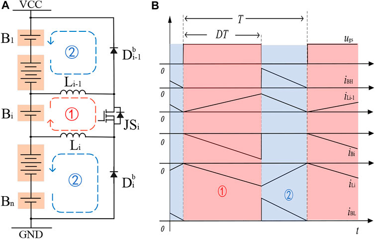
FIGURE 4. The foundational working principle of CP mode. (A) Modular and power flow. (B) Key waveforms.
In Table 2, the conditions of each component are presented. In any cell to the rest mode, assuming that Bi is overcharged; thus, its energy should be delivered to the rest of the pack. Then, the mathematical formula for a switching cycle is given as well.
3) When the switch Tia is on (0 < t < DT), the current flowing through the inductor Li will rise linearly; at this time, the front i battery charges the inductor Li, and the inductor Li stores energy;
4) When the switch Tia is off (DT < t < T), the current flowing through the inductor Li decreases linearly, and the inductor Li charges the battery Bi+1 to Bn;

TABLE 2. The state of the component under CP mode (Bi > Average).
The values of the inductor are calculated as follows. When the current is continuous, there are two states of inductors: charging or discharging. During 0∼ton period, the inductor Li is charged by battery Bi and the current increases linearly. When t = ton, the inductor current reaches the maximum value Ipeak, the increased value is ΔiLi.
During ton ∼ T period, inductor Li discharge to battery Bi + 1. When t = T reaches the minimum value Imin and the reduction amount is ΔiLi,
According to the principle of volt-second balance, there is Vj + 1/Vj = D/1−D. The average inductor current is equal to the sum of the average currents flowing during charging and discharging.
Therefore, the inductance value is as Equation 11.
Assuming that the switching frequency is 10 kHz, the rated voltage of the normal battery is 3.7 V, the duty cycle is 0.5, and current variation is 0.2 A, so the inductance is
Modeling Design and Analysis
As a typical dynamic system, the converter’s behavior can be expressed by the space state equation. When the differential values of the state variables are all zero, the system is in equilibrium. The SSM can be obtained by applying a small disturbance at the equilibrium point of the system. A SSM is a commonly used analysis model in electronic engineering, which uses linear equations to approximate the properties of nonlinear components. When the system returns to a small area around the equilibrium point after being subjected to a small disturbance, it means that the system is locally stable at the equilibrium point.
In this section, the state-space representation model and SSM have been built separately in MATLAB to demonstrate the characteristics of the proposed circuit. To enable more accurate battery energy equalization, a noise cancellation method on the basis of information collection from neighboring nodes of the communication network is employed.
State-Space Representation Model
Many kinds of research have been proposed to build SSMs, one of which is the state-space averaging method. This developed method for buck-boost circuits is introduced in references (Maniktala, 2008) and (Erickson, 2010), to which readers could refer.
The state-space model is based on a network structure model composed of linear RLC components, independent power supplies, and periodic switches. Through the on-duty ratio D of the power switch device, the average state variable in a period is obtained, and the nonlinear circuit is transformed into an equivalent linear circuit. The space state equation of the converter sub-module proposed in this paper is shown in Equation 12.
To facilitate simulation and calculation, it can be rewritten as a matrix form of Eq. 13
where the coefficient matrices A and B are
Small-Signal Model
When the perturbation method is adopted to solve the SSM, it is necessary to make a slight disturbance of the input voltage and the duty cycle near the DC operating point, which causes the state variables such as the inductor current and output voltage in the converter to also produce slight disturbances. To introduce the disturbed variables into the state space average equation of the inductor current, and the state space average equation of the inductor current and the capacitor voltage with the disturbance can be obtained as shown in Equation 14:
While eliminating the steady-state equation, the second-order small-signal term is omitted, so that the nonlinear AC small-signal equation of state can be obtained:
According to the equivalent circuit of the SSM, the converter’s duty cycle–to–output voltage transfer function Gvd(s), Gid(s), and Gvi(s) could be obtained separately.
To derive the SSM in CP mode, it can be further considered that it is composed of a linear combination of two PP modes. Accordingly, the SSM of this converter in CP mode and its transfer function can be obtained.
The SSM is developed to verify its stability and dynamic characteristics. To avoid excessive deviation caused by the disturbance and the equalization process toward the wrong direction, a small signal model is set to judge the impact of the disturbance. During operating, this can improve the accuracy of the model. Eq. (16) represents the output voltage and duty cycle transfer function in the SSM. Eq. (17) represents the current and duty cycle transfer function. Eq. (18) represents the voltage and current transfer function. Corresponding Bode plots are shown in Figure 5.
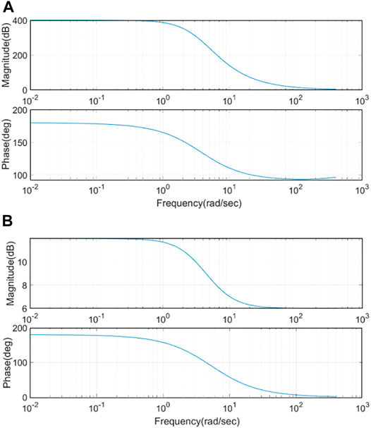
FIGURE 5. Bode plot for small signal model (A) Gvd transfer function (B) Gid transfer function.
Simulation and Experiment Results
To further verify the feasibility of the circuit design proposed in this paper, an electromagnetic transient model is built in PSIM and the experiment on four batteries is implemented as well.
Simulation System and Design
To verify the correctness of the SSM, the equalization circuit topology shown in Figure 1 was built in PSIM with PP mode, CP mode, and PP&CP mode, respectively. Some key parameters of the components used have been provided in Table 3.
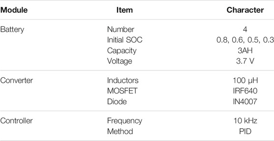
TABLE 3. key parameters in the simulation.
The specific steps of our experiment are as follows.
Step 1: Establish a four-battery test platform. Set the initial SOC of battery (80%, 60%, 50%, and 30%). All components values are selected according to Table 3.
Step 2: Run the equalization system in PP mode, CP mode, and CP&PP mode, respectively.
Step 3: Collect the SOC of batteries and draw the dynamic response under different methods.
Step 4: Compare the performance and analyze the power loss.
Dynamic Response
To further demonstrate the process of equalization, the system with PP mode and CP mode is built in MATLAB, respectively. Figure 6 and Figure 7 show the key waves of the converter under PP mode and CP mode. From the waveform, two working modes have similar principles but different objects. The overcharged batteries are discharging while the inductor observes the energy from them. Then, the energy is delivered to the discharged batteries from the inductor.
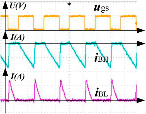
FIGURE 6. PP mode dynamic waveform.
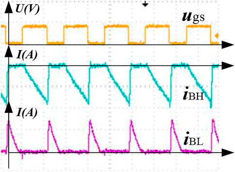
FIGURE 7. CP mode dynamic waveform.
In Figures 6, 7, the yellow waveform represents the pulse sequence of the voltage. The peak voltage is 10 V. The green waveform represents the current state of discharging the battery with the higher power. Purple waveform represents the current state of charging the battery with lower power. The peak value of the charging current is 2 A. When the switch is turned on, the battery with a higher power is gradually discharged, and the battery with lower power remains unchanged. When the switch is turned off, the battery with higher power remains unchanged, and the battery with lower power is rapidly charged. Therefore, the difference between the cells gradually becomes smaller, and the equalization process ends until the error meets the equalization requirements.
Comparison and Results Analysis
As illustrated in the previous section, the dynamic waves are presented and analyzed in detail. In this section, the four battery equalization system has been built in PSIM to further verify the proposed method. The initial SOC of each battery is set as 80%, 60%, 50%, and 30%. To make the results more visualizable, the capacity of batteries is relatively low which will speed up the speed of balancing and have no effect on the conclusion. The CP mode and PP mode are implemented on the equalization separately. Besides, the two modes could function synchronously which will increase the speed of equalization slightly. The results of the above three modes are printed in Figure 8, and more details during the process could be found in the following description.
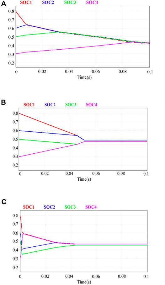
FIGURE 8. The results of four battery equalization systems. (A) PP mode. (B) CP mode. (C) PP&CP mode.
Under the PP mode shown in Figure 8A, the SOC of these four batteries is approximately the same after 90 ms. It should be mentioned that the B2 should be discharged directly, but it was charged first and then discharged during the equalization process. This undoubtedly causes some power and makes the system relatively time-consuming. As for CP mode, presented in Figure 8B, the equalization time is about 50 ms, which is significantly reduced compared to PP mode. That is probably due to the power delivery of the CP mode being simple and direct which reduces the energy circulation. Finally, both modes could work together to make the system time-saving. The control complexity of the combined mode is equal to the individual mode. As is shown in Figure 8C, there is still energy circulation, which is the cost of fast equalization. To further reduce the power loss, the recharged battery should be idling, but the time is the cost as well. Therefore, the contradiction between equalization time and equalization loss always exists. How to balance them and proper evaluation methods for practical projects are key issues and should be further developed.
Economic Analysis
To further clarify the superiority of the converter proposed in this paper, it is compared with two conventional schemes in the same settings. By collecting the average equalization time of the three converters, the data are processed as shown in Figure 8. Further, the cost and the efficiency of the system are also plotted as shown in Figure 9, as detailed in the analysis below.
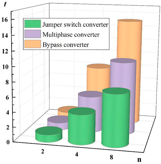
FIGURE 9. The average equalization time of the three converters.
Initially, assuming that the inconsistency of battery energy satisfies a normal distribution, and the average equilibrium time of the two battery modules is recorded as t0, the average equilibrium time of each system in the experiment can be obtained. In the experiment, when the number of batteries is two, both the multi-phase interleaved converter and the jumper switch converter degenerate into the bypass converter, and the average equalization time of the equalization process is t0. When the number of batteries is four, the average equalization time of the three converters is increased. The average equalization time of multi-phase interleaved converters and jumper switch converters is slightly lower than that of bypass converters. This trend is obvious as the number of batteries increases. Furthermore, when the number of batteries increases, the advantages of the jumper switch converter will gradually accumulate, and its average equalization time will be much shorter than the other two solutions.
For evaluation on battery pack equalizers, the efficiency and cost are key determinants in considering the system’s merits as well, which are especially important in practical engineering. In our experiments, we tested the equalization process of eight batteries with bypass, multi-phase interleaved converter, and jumper switch converter, respectively. The data of the respective processes were collected, organized, and analyzed and are shown in Figure 10.
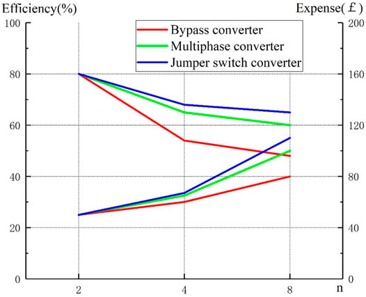
FIGURE 10. The expense and efficiency of the three kinds of converters.
In terms of cost, the bypass converter has the lowest circuit cost due to its simple structure. Because of the addition of jumper switches, the cost of jumper switch converters is slightly higher than that of multi-phase interleaved converters. In terms of efficiency, as the number of batteries increases, the efficiency of the bypass equalizer drops sharply, whereas the average efficiency of jumper switch converters and multi-interleaved converters slowly decreases. It is not difficult to predict that, with the further increase in the number of batteries, the loss of the bypass converter will no longer meet the practical engineering needs. For practical projects, comprehensive consideration can also be made according to the pursuit of equalization speed and equalization time, to select a suitable converter topology.
Conclusion and Future Work
To mitigate the issue of battery inconsistency, a staggered parallel converter with jumper switches is proposed and implemented in this paper. Energy could be transformed from the overcharged cells to the rest in strings and also between packs to packs. To maximize the structural advantages of the topology, the CP mode, PP mode, and CP&PP mode are proposed and verified to significantly improve the equalization speed. The simulation experiment further proves the proposed design and control, and the experiment shows that the method greatly shortened the equalization time than the traditional method. Our contribution could be summarized as follows:
1) The jumper switches enable another energy path that could directly release the energy of the overcharged battery to the rest packs. However, there is no difference between PP and CP mode in the two-battery system. In a three-battery system, the efficiency of PP and CP is almost the same. However, one jumper switch can be applied in the CP mode, leading to one more energy transfer way than PP mode. In a four-battery system, the CP mode that uses two jumper switches will be more efficient than the PP mode. It can be concluded that the proposed topology and control will have superior performance especially when it comes to the large battery system.
2) The characteristic of the two modes (CP and PP) is different when it is applied to the same condition. A combined method (CP&PP) is a good attempt that proves the performance will depend on the specific case which deserves further research. We will develop a comprehensive method to maximize the benefits of both models in recent future.
To cope with the wide range of practice engineering requirements, the demand for more flexible and efficient equalization topologies will last for a long period. It is worth mentioning that switching stress needs to be considered when balancing battery packs in practical projects such as electric vehicles and battery energy storage platforms so that high-performance switching devices (such as gallium nitride devices, etc.) should be selected. Besides, when the converter works in the boost mode because its boost ratio is limited, it is necessary to use as many batteries as possible to transfer energy to a few batteries in the buck mode. Some potential work on the energy balance of lithium battery packs include 1) to consider the adoption of soft switching technology and coupled inductors, thereby further reducing the loss and volume of the equalizer; 2) to consider the layered grouping strategy and hybrid modes, some advanced control methods could be considered such as game theory and ant colony algorithm.
Data Availability Statement
The raw data supporting the conclusion of this article will be made available by the authors, without undue reservation.
Author Contributions
XW proposed a novel battery pack equalization system. GC designed and implemented the balancing circuit and its control. LH drafted the manuscript and ZL finalized and polished the manuscript.
Conflict of Interest
The authors declare that the research was conducted in the absence of any commercial or financial relationships that could be construed as a potential conflict of interest.
Publisher’s Note
All claims expressed in this article are solely those of the authors and do not necessarily represent those of their affiliated organizations or those of the publisher, the editors, and the reviewers. Any product that may be evaluated in this article, or claim that may be made by its manufacturer, is not guaranteed or endorsed by the publisher.
References
Dai, S., Zhang, F., and Zhao, X. (2021). Series-connected Battery Equalization System: A Systematic Review on Variables, Topologies, and Modular Methods. Int. J. Energ. Res. 45, 19709–19728. doi:10.1002/er.7053
Lin, N., Ci, S., Wu, D., and Guo, H. (2018). An Optimization Framework for Dynamically Reconfigurable Battery Systems. IEEE Trans. Energ. Convers. 33 (4), 1669–1676. doi:10.1109/tec.2018.2850853
Liu, K., Yang, Z., Tang, X., and Cao, W. (2020). Automotive Battery Equalizers Based on Joint Switched-Capacitor and Buck-Boost Converters. IEEE Trans. Veh. Technol. 69 (11), 12716–12724. doi:10.1109/TVT.2020.3019347
Maniktala, S. (2008). Proficient in Switching Power Supply Design. Beijing: People's Posts and Telecommunications Press.
Mestrallet, F., Kerachev, L., Crebier, J.-C., and Collet, A. (2014). Multiphase Interleaved Converter for Lithium Battery Active Balancing. IEEE Trans. Power Electron. 29 (6), 2874–2881. doi:10.1109/tpel.2013.2276152
Peng, W., Cai, T., Chao, Z., Zhou, M., and Han, Y. (2021). “Distributed Cooperative Consensus Control Strategy for Battery Equalization System,” in Proceedings of the CSEE, Rome, Italy, June 21-23, 2021.
Shan, Z., Dai, S., Wei, Y., and Sun, Y. (2020). Analysis and Design of Multilayer Multiphase Interleaved Converter for Battery Pack Equalization Based on Graph Theory. Int. J. Energ. Res. 44, 2580–2593. doi:10.1002/er.4975
Shang, Y., Cui, N., Duan, B., and Zhang, C. (2017). A Global Modular Equalizer Based on Forward Conversion for Series-Connected Battery Strings. IEEE J. Emerging Selected Top. Power Elect. 6, 1456–1469. doi:10.1109/jestpe.2017.2768388
Shang, Y., Xia, B., Lu, F., Zhang, C., Cui, N., and Mi, C. (2017). “A Switched-Coupling-Capacitor Equalizer for Series-Connected Battery Strings,” in IEEE Transactions on Power Electronics, Tampa, FL, USA, March 26-30, 2018.
Shang, Y., Zhang, C., Cui, N., and Guerrero, J. M. (2015). A Cell-To-Cell Battery Equalizer with Zero-Current Switching and Zero-Voltage Gap Based on Quasi-Resonant LC Converter and Boost Converter. IEEE Trans. Power Elect. 30, 3731–3747. doi:10.1109/tpel.2014.2345672
Shang, Y., Zhang, C., Cui, N., and Mi, C. (2018). “A Delta-Structured Switched-Capacitor Equalizer for Series-Connected Battery Strings,” in IEEE Transactions on Power Electronics, Tampa, FL, USA, March 26-30, 2018. doi:10.1109/tpel.2018.2826010
Song, C., Li, H., Xin, C., and Wen, W. Q. (2017). The Cornerstone of Energy Internet: Research and Practice of Distributed Energy Storage Technology. Scientia Sinica (Informationis) 47 (02), 149–170. doi:10.1360/N112014-00034
Tang, X., Gao, F., Liu, K., Liu, Q., and Foley, A. M. (2021). A Balancing Current Ratio Based State-Of-Health Estimation Solution for Lithium-Ion Battery Pack. IEEE Trans. Ind. Electron, 762–773. doi:10.1109/TIE.2021.3108715
Wang, J., Dai, S., Chen, X., Zhang, X., and Shan, Z. (2019). Bidirectional Multi-Input and Multi-Output Energy Equalization Circuit for the Li-Ion Battery String Based on the Game Theory. Complexity 2019, 1–17. doi:10.1155/2019/7081784
Wang, S., Yang, S., Yang, W., and Wang, Y. (2020). A New Kind of Balancing Circuit with Multiple Equalization Modes for Serially Connected Battery Pack. IEEE Trans. Ind. Electron. 68 (3), 1. doi:10.1109/TIE.2020.2973886
Wang, Y., Zhang, C., Chen, Z., Xie, J., and Zhang, X. (2015). A Novel Active Equalization Method for Lithium-Ion Batteries in Electric Vehicles. Appl. Energ. 145, 36–42. doi:10.1016/j.apenergy.2015.01.127
Wei, Y., Dai, S., Yu, J., Wu, S., and Wang, J. (2019). “Research on Status and Prospects of Battery Energy Storage Stations on Energy Internet,” in 2019 IEEE 3rd Information Technology, Networking, Electronic and Automation Control Conference (ITNEC) IEEE, Chengdu, China, March 15-17, 2019. doi:10.1109/itnec.2019.8729063
Wei, Y., Dai, S., Wang, J., Shan, Z., and Min, J. (2018). Hybrid Natural and Forced Active Balancing Control of Battery Packs State of Charge Based on Partnership for a New Generation of Vehicles. J. Electr. Comput. Eng. 2018, 5130358. doi:10.1155/2018/5130358
Wei, Y., Dai, S., Wang, J., Shan, Z., and Min, J. (2019). Switch Matrix Algorithm for Series Lithium Battery Pack Equilibrium Based on Derived Acceleration Information Gauss-Seidel. Math. Probl. Eng. 2019, 8075453. doi:10.1155/2019/8075453
Xiaolin, W., Ka, C., and Yat, F. (2018). Non-Equal Voltage Cell Balancing for Battery and Super-capacitor Source Package Management System Using Tapped Inductor Techniques. Energies 11 (5), 1037. doi:10.3390/en11051037
Keywords: battery inconsistency, equalization converter, staggered parallel topology, jumper switches, small-signal model
Citation: Wang X, Huang L, Chen G and Li Z (2022) Design and Implement of Staggered Parallel Lithium Battery Equalization Converter With Jumper Switches. Front. Energy Res. 10:843453. doi: 10.3389/fenrg.2022.843453
Received: 25 December 2021; Accepted: 18 January 2022;
Published: 14 March 2022.
Edited by:
Sudhakar Babu Thanikanti, Chaitanya Bharathi Institute of Technology, IndiaReviewed by:
Pradeep Vishnuram, SRM Institute of Science and Technology, IndiaCarlos Fernandez, Robert Gordon University, United Kingdom
Copyright © 2022 Wang, Huang, Chen and Li. This is an open-access article distributed under the terms of the Creative Commons Attribution License (CC BY). The use, distribution or reproduction in other forums is permitted, provided the original author(s) and the copyright owner(s) are credited and that the original publication in this journal is cited, in accordance with accepted academic practice. No use, distribution or reproduction is permitted which does not comply with these terms.
*Correspondence: Xueqi Wang, 2019109105@ctgu.edu.cn