Battery management system enhancement for lithium-ions battery cells using switched shunt resistor approach based on finite state machine control algorithm
 Shimaa A. Hussien1
  Amal BaQais
 Mostafa Al-Gabalawy
- 1Electrical Department, College of Engineering, Princess Nourah Bint Abdulrahman University, Riyadh, Saudi Arabia
- 2Department of Chemistry, College of Science, Princess Nourah Bint Abdulrahman University, Riyadh, Saudi Arabia
- 3Electrical Power Engineering Department, Faculty of Engineering, Suez University, Suez, Egypt
Due to their favorable characteristics, lithium-ion batteries have a dominant share of the battery market. There are a number of issues related to the use and management of Lithium-ion batteries in this paper, specifically with regard to the safe operation of the batteries as well as methods for balancing their cells. With the help of a passive cell balancing algorithm and a cell measurement circuit, a battery management system with a passive cell balancing algorithm has been developed. The purpose of this paper is to improve the efficiency of the balancing algorithm by implementing and analyzing a cell modelling method from the literature, with the aim of improving its performance. The results of this study showed that the use of the cell modelling system was able to improve the balancing algorithm’s balancing and charging times by 12.6%. Further, to validate the results obtained from the measurement system and the cell modelling system, an analysis was conducted of uncertainty propagation in order to validate the results. As part of future research, broader testing conditions may be used in order to better understand the positive impact of the cell modelling system on the balancing algorithm in the future.
1 Introduction
Identifying the requirements of the application before designing a battery is an essential part of the process. The most important requirements of the design are the cost, the maximum power, and the total energy consumption. A design that allows for moderation can result in a simplified number and type of cells based on the total amount of power that the cell can provide. According to the maximum power rating of the power electronics, the cell chemistry and the power electronics will be chosen. In addition to the upfront dollar value of batteries and components, the overall cost of batteries and components includes time-dependent and ongoing factors, such as how long a battery can be used and how much electricity is needed for charging it. Due to the economics of the application system, a passive balancing system has been selected for the system of this application. This paper presents a comparison of several circuits that are intended for balancing cell voltages in multi-cell battery packs, which is a critical component. The low cost of passive balancing means that it is more affordable than alternative balancing methods, despite its lower efficiency due to its lower power consumption.
Habib et al. developed voltage balancing circuits based on LC energy converters. Over-excess energy is directly transferred from the higher to the lower cell. An LC tank is used for storing n energy storage devices and four bidirectional MOSFET switches. A high efficiency, fast balancing speed, small size, low cost, and maximum energy recovery were also claimed for the active balancing circuit. Through complementary plus wide modulation signals, all MOSFET switches are controlled using a synchronous trigger pattern. Cyclic charging and discharging of a series battery or super capacitor string can be achieved with zero voltage gaps between adjacent cells. According to this claim, this circuit has a resonant frequency that is the same as the switching frequency. According to experimental results of 95% (3.958 V) and 66% (3.712 V), respectively, after 79 min, the voltage difference between two 4200 mAh Li-ion cells will be zero (0 V) (Habib and Hasan, 2023).
A circuit developed by Yun et al. balances out the imbalance in the battery’s power that can lead to overcharging or over-discharging. A fifth-order VBSRCKF equalization variable is used by the authors to equalize the power of each battery pack using a controlled source equivalent replacement second-order model and a fly-back converter as the energy transfer circuit. According to the authors, this scheme is effective for solving the problem of inconsistency in battery energy caused by inconsistent battery performance, as well as controlling the equalizing speed and the equalizing current, so batteries are more protected (Yun et al., 2023). Data-driven anomaly detection in battery packs is based on real-time voltage and temperature data from multiple Li-ion cells. For mean-based residuals between cell groups, Principal Component Analysis is used. Analysis of residuals was carried out using a cumulative sum control chart. Additionally, after cell balancing, voltage signals are distorted due to mild short circuits associated with external short circuits. By enabling the detection of anomalous module balancing events within 14 min, the authors prove that temperature plays a critical role. The proposed approach is also tested with anomalies injected into a model-based locomotive. The proposed anomaly detection approach detects and traces voltage and temperature anomalies accurately. According to the proposed method, 56% fewer false negatives, 42% fewer false positives, and 60% fewer missed anomalies are achieved compared with direct thresholding (Bhaskar et al., 2023).
Battery management systems (BMSs) monitor and control charging/discharging, estimate state of charge, protect batteries, calculate state of health, balance cells, and manage temperature. Control operations enable accurate, safe, and reliable battery operation, reduce individual cell damage, and extend battery life, according to this claim. Based on a balancing model, BMS balance performance was estimated. The Master-Slave Balancing Model (MS-BMS) validates the balancing model. BMS Master and Slaves were balanced using bidirectional fly-back converters with photo-MOS arrays. Balancing skill, circuit power, equalization speed, control simplicity, modularization simplicity, and cost were considered in designing the BMS. Under the five balancing conditions, the average absolute error of the balancing duration results is 3.12% when compared with the simulations’ results. This comparison demonstrates the advantages of the proposed BMS, such as equalization speed, control simplicity, modularization simplicity, and cost (Lee et al., 2023). Thiagarajan et al. show that battery technologies are developing exponentially for the use of fuel in electric vehicles, resulting in competently designed and implemented battery management systems. A voltage difference perturbs the performance of the battery pack through an optimized control strategy. Battery-operated vehicles can be charged and run more easily. Switching the resistors correctly controls the charging circuit. Thermal balance of resistors is achieved through simulation using a thermal power dissipation model. MATLAB Simulink is used to test variable cell voltages. A passive cell balancing technique is used to balance voltage errors between multiple cells in a stack. A state of charge imbalance is the main cause of passive cell balancing problems. Battery charging conditions are considered for parameter estimation in the balancing technique (Thiagarajan et al., 2023). Battery-balancing auxiliary power modules by Wang et al. offer simplified topologies without compromising functionality or balancing modes. The proposed system uses dual-active half bridges to reduce the number of switches compared with conventional dual-active bridges. Coreless transformers provide energy transfer and isolation without a transformer core. Both changes reduce costs of redistributive balancing. In coreless transformers, there is less coupling between topological models than in cored transformers. In addition to transformer currents and output powers, a revised model includes coupling coefficients. Following an analysis of these, balancing modes are experimentally verified. Models can be used to select MOSFETs and guide coreless transformer design. Analyzing similar topologies can result in 14% cost reduction (Wang et al., 2023a). An application of Turksoy et al.’s balancing control strategy is presented. An unidirectional common flyback was used to convert excess energy from the cells to the battery pack. A common flyback converter transfers excess energy from the cells to the battery pack. The algorithm aims to minimize energy loss by removing imbalances between battery packs in the shortest time possible (Turksoy and Ahmet, 2023). Vu et al. have developed an internal heating technique based on balancing the temperature and state of charge of the battery cells with the geometrical and thermal characteristics of the battery pack. The temperature and SOC variance in a battery pack can be reduced by pulse heating different groups of cells at different times and in different orders. A long period below zero degrees Celsius can be achieved with balanced SOCs and temperatures between cells, according to the simulation results (Vu and Shin, 2023). For equalizing between cells and between cell groups, Wu et al. used LC oscillation circuits and single inductor equalizing circuits. In order to determine the appropriate operating current range for a given battery state of health (SOH), a variable domain fuzzy control strategy is used; the equalization current is dynamically adjusted based on the mathematical relationship between it and the operating current. This equalization method was tested through an experimental platform and simulations. After 1,200 charge/discharge cycles, experiments demonstrate a 25% improvement in equalization speed, a 6% reduction in capacity decay, and an extended service life compared to traditional fuzzy equalization strategies (Wu et al., 2023).
An efficient method of modeling, selecting parameters, and analyzing lithium-ion batteries’ operation can be developed by Gaslov et al. using a numerical model of a lithium-ion battery integrated into a vehicle. Based on a complex functional 1D model of the upper level, it can predict how lithium-ion battery packs will function based on vehicle type and control system (active or passive balancing) (Gaslov et al., 2023). Li and colleagues propose a double-layer equalization approach based on reconfigurable topology and converter active equalization. Reconfigurable topology in the inner layer ensures a balanced set of cells. Increasing the state of charge of the lowest cell in a battery group reduces energy transfer losses. This topology can also reduce complexity and component count. Each battery group contains Buck-Boost converters connected in series. While the SOC varies, the converter maintains a stable output voltage. The proposed method is validated using a Matlab/Simulink equalization circuit. Despite balancing the battery pack, the proposed method maintains a stable output voltage. A comparison of the proposed equalization method to the conventional active equalization method demonstrated that the proposed equalization method is significantly more efficient (Li et al., 2023). Using equalizing technology, Van et al. balanced active cells by maintaining their temperatures and currents within an appropriate range. Cell-to-cell balancing circuits based on CUK converters were used to model the state of charge (SOC) and temperature dynamics of cells in a pack. Optimal control for active cell balancing was formulated with constraints on cell current and temperature. This non-linear optimal problem is solved using sequential quadratic programming (SQP) to feed cell balancing circuits. According to the results, cell balancing occurs quickly and adaptably, depending on discharge/charge currents, temperature increase limits, and technical constraints of balancing circuits (Van, 2023).
For balance and unbalance operations, a dynamic voltage compensator (DVC) is proposed based on a battery energy storage system. Medium-voltage distribution systems are supported during voltage sags by adding the compensation voltage to the transformer’s grid side and switching its primary winding. Asymmetrical and symmetrical grid-side voltage sags, along with two voltage-current closed-loop control strategies, are constructed by identifying symmetrical and asymmetrical grid-side voltage sags. Positive and negative sequence inner current loops are enhanced with circulating current suppression algorithms to reduce DC bias caused by circulating current between the primary windings. The proposed voltage support methodology is verified through simulations and experiments (Xu et al., 2023). This linear fast charger uses both a digitally controlled bi-directional linear regulator and a current-mode linear regulator (LR). To increase efficiency and reduce volume and cooling complexity, state-of-the-art isolated dc-dc converters rely heavily on high-voltage capacitors, high-frequency switches, and high-power magnetics. With the same rated EV charge power, the LR loses 83.6% less. LFC stations with three ports achieve 93.4% efficiency, while wasting 28.6% less energy than BA-DCFCs. Active state-of-charge and health balancing are integrated into LFCs at the station, BESS, and LR levels (Assadi et al., 2023). Zhang et al. proposed RVSF and PIC as fast state of charge balancing control strategies. First, an RVSF-based balancing control is introduced that integrates energy interaction between storage units during balancing to enhance traditional droop SOC controls. A PIC-based SOC balancer is then proposed. During SOC balancing, the PIC strategy ensures at least one storage unit operates at maximum power flow. Moreover, a strategy for dealing with systems with inconsistent energy storage units is presented. A plan with multiple energy storage units is simulated using PLECS and MATLAB simulation software. Various operating conditions show that the proposed strategies are valid and feasible, and they increase system load capacity and duration in hardware-in-the-loop simulations (Zhang et al., 2023). According to Yun and colleagues, fires caused by gradual damage are caused by a voltage imbalance in the cell, which inflows compensation current. As a result of their different capacities, batteries connected in series age at different rates, which leads to a rise in compensatory current until a fire occurs. In this study, battery-capacity deviations increase with battery age, resulting in higher compensation currents. As a result of the proposed solution, a wider range of battery-capacity deviations will be permitted. With Simulink simulations, we identified problems, suggested improvement measures, and identified improvement measures to verify the proposed method (Yun and Kee, 2023).
From the literature, many approaches are implemented to make the cells balance. A complex control has been required specially for the capacitors and transformers unit that would be applied. While using a resistor requires a simple control algorithm, this resistor also introduces a robust balancing circuit. Moreover, the applied approach could be applied in wide battery conditions. In detail, an algorithm for controlling the shunt resistors is proposed by the present paper which is based on the use of finite state machines (FSM). This algorithm is applicable to the enhancement of the battery management system of lithium-ion battery cells, which are equipped with shunt resistors. A second section introduces an overview of the battery model as well as a set of topologies for balancing cells in different systems and how they are implemented. In Section 3, the measurement of voltage, current, and temperature is demonstrated so that how they are needed in the process of controlling the devices. A discussion of the effects of the proposed control algorithms on the measurements is shown in Section 4 along with measurement results. The final conclusion and future work will be discussed in Section 5 of the document.
2 Mathematical modelling
Battery has been used in applications, but the main usage of the battery now is electric vehicles (EVs). The configuration of the EV-battery system is represented in Figure 1A. The battery and electric vehicle behavior is simulated by many mathematical models, executed with a tunable integration time. The model outputs consist of the battery current and the cell voltages and the corresponding versions of the measurement noise and. They form the input of the battery state estimator, which in turn computes the SOC estimation as well as the vector of equivalent circuit model (ECM) parameters. The traction battery, simulated by the application, and the battery state estimator, implemented in an embedded system, interact by using digital signals only. Consequently, the interface between the hardware in loop (HiL) model and the hardware can be implemented as a digital communication layer, without the need for reproducing the power interface of the battery, as instead required for validating other BMS functions such as cell balancing. The battery model is able to simulate a battery composed of a given number of series-connected cells. The only input is the battery current which is the same for all the series-connected cells, as shown in Figure 1B (Schmitt et al., 2023; Çorapsiz and Kahveci, 2023).
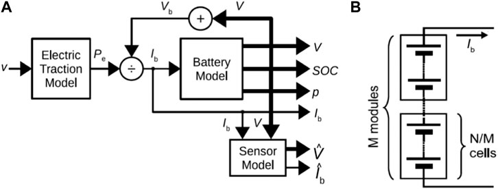
FIGURE 1. (A) The complete configuration of the EV-battery system, (B) connection of the battery cells.
Figure 2 shows the ECM of the battery, where at each time step, the model generates the arrays of the cell voltages
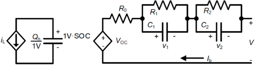
FIGURE 2. Electric circuit model with two RC branches of the battery cells.
The model is then generalized to simulate a cell with the same technology but different capacity by proportionally scaling the lookup table values with the capacity, directly for the resistive elements and inversely for the capacitive ones. Regarding the open-circuit voltage only the dependency on SOC is considered, while the capacity is kept constant during the tests. The variability of the cell behavior is considered by setting the initial SOC, the model parameters and the capacity of each cell individually (Al-Gabalawy, 2021a).
Figure 3 shows the different approaches of battery cell balancing, where these approaches are divided on passive and active. In the passive approach, a fixed shunt resistors are installed in parallel with the battery cells. Maybe, there is a switch installed to control the position of this resistor as in Figure 4A, B, and the main advantages of this approach are low cost and easy implementation. Active balancing system contains two families. In the first one (charge shuttle), it might use a switched capacitor or multiple switched capacitors in order to enhance the cells balancing performance as in Figure 4C, D. While, in the second one (energy converter) a transformer is installed for the battery cells, where this transformer might be switched or shared as in Figure 4E, F

FIGURE 3. The different approaches of the battery cells balancing system.
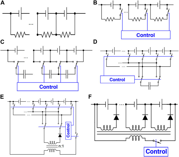
FIGURE 4. The different configurations of the battery cells balancing system, (A). Passive-fixed resistor, (B). Passive-switched resistor, (C). Active-charge shuttling-one switched capacitor, (D). Active-charge shuttling-multiple switched capacitors, (E). Active-energy convertor-switched transformer, (F). Active-energy converter-shared transformer.
Specifically, in order to balance passively, it uses the simplest electronic design. As a general rule, each cell’s charge is drain by placing a resistor in parallel with it. As heat is dissipated from the cell, the energy is removed. As a result, high-voltage cells will self-discharge more quickly than low-voltage cells if the balancing current is greater for the high-voltage cells. It is important to note, however, that the circuit dissipates charge regardless of whether the pack is balanced or not. When cell voltage falls below a certain point, zener diodes are used to shut off balancing. A “100% SOC” setpoint is maintained with the zener voltages. In the case of lead-acid cells, about 2.2 V. A cell’s charge is depleted when its voltage rises above the zener set point, which activates the resistor path. It is possible to replace the zener diode with a BMS-controlled switch in the above example, which will also work for lithium-ion chemistries. Transistor circuits are used in this switch. It is more complicated because the transistor must be controlled electronically, but it is also more flexible when it comes to balancing strategies. Overcharged cells are enabled to drain by the BMS when switches are closed. There is no longer as much concern about the added complexity. An internal transistor switch can be controlled by modern battery-stack monitoring chips, whereas an external transistor switch can be controlled more quickly. Any passive balancing method has the advantage that its circuitry is simple (and consequently low-cost). There are three general categories of active balancing circuits; move charge via switched capacitors, move energy via transformer/inductor designs, and discharge high cells with DC-DC converters. Compared with the number of batteries in the circuit below, there is one fewer capacitor. Switching is done repeatedly back and forth by single-pole-double-throw transistor circuits (no intelligence behind the switching). Two adjacent cells can be considered. Voltages of the high-voltage and low-voltage cells are equalized by charging and discharging the capacitors. Battery packs can equalize themselves over time. From one end of a pack to the other, charge takes a long time to propagate. The charge can be moved directly from a high-voltage cell to a low-voltage cell in a switched capacitor. Capacitor-based designs have the disadvantage of relying on voltage differences between cells to work. It is very uncommon for lithium-ion chemistries to have large variations in voltage between cells despite a large variation in SOC. Switching the primary rapidly creates an approximate waveform, which is reproduced at the secondary with the switched transformer approach. A transformer with a wound ratio of
Figure 5 illustrates a new approach called Shared bus where one small dc–dc converter is used for each cell and a capacitive shared low-voltage bus is used to balance each cell. It is normal to map balancing metrics to a DC level between 9 and 14 volts. In addition to SOC and voltage, it is possible to use more advanced metrics. If the cell’s metric is below the shared-bus voltage, charge is transferred from the low-voltage bus to the cell using a controlled DC–DC converter. If the cell’s metric is above the shared-bus voltage, charge is transferred from the cell to the low-voltage bus. It is possible to replace bidirectional DC-DC converters with unidirectional converters if the load power is large and consistent enough on the low-voltage bus. With a single isolated shared bus and no additional communication, the H-bridge DC-DC converter reduces costs by combining a modular structure with a simplified isolated shared bus. Compared to passive balancing, this solution can achieve greater cost-effectiveness since it is able to balance and replace the large DC-DC converters currently used to convert pack voltage to 12 volts DC for vehicle accessories, as well as achieve better balance (Al-Gabalawy, 2021b).
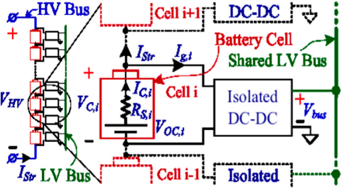
FIGURE 5. The share bus battery cells balancing approach.
3 Monitor and control algorithm
An MCU manages all of the BMS systems and algorithms. Its responsibilities are: collecting system measurements, controlling system isolation and charging, applying the balancing algorithm, deriving quantities such as
Measuring the terminal voltage of each cell is done using an analog to digital converter (ADC) polled by the MCU at 2Hz. The voltage from ground to the negative terminal of a particular cell will be referred to as the common mode voltage (VCM), while the voltage across the cell will be referred to as the differential voltage (
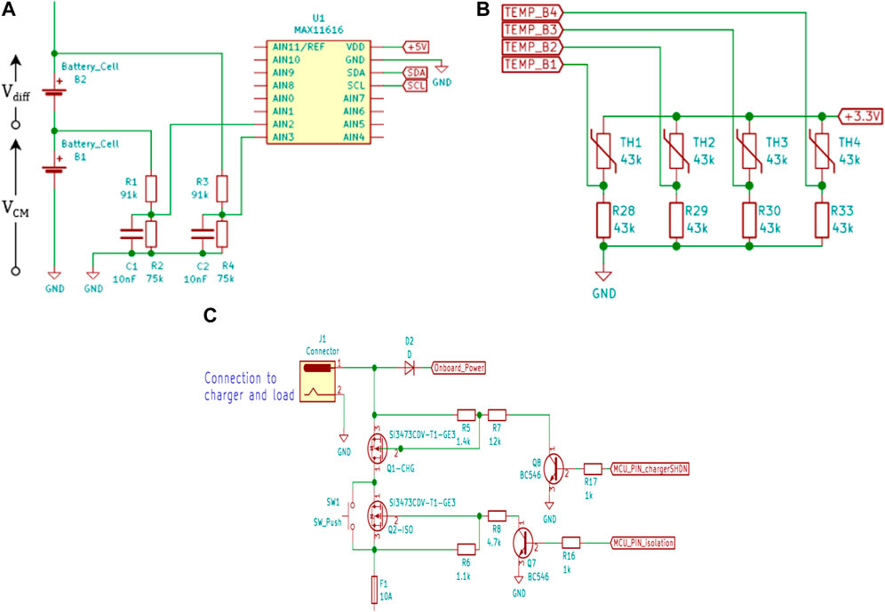
FIGURE 6. (A). Differential Voltage Divider ADC Input (for one cell only), (B). Cell temperature sensing circuit, and (C). Battery input protection and charging control.
The cutoff frequency for the filter can be seen in Eq. 1, where
For optimum results, both channels of the differential input would be connected to the sensing points with identical voltage dividers. Any mismatch in the resistors results in the presence of
The battery current was measured with an INA219 dedicated current sensor and a 0.1 Ω shunt resistor. In each cell, the current was simply calculated from the battery current minus the current through the shunt resistor, which is known through Ohm’s law and the state of the shunt switch. The reasons behind selecting the INA219 were its bidirectional capability and high resolution. The adopted shunt resistor gave the system a 0.1 mA resolution and a maximum current of 3.2 A. This range can easily be adjusted by replacing the resistor during development. The sense resistor was placed in a high-side configuration, above the positive terminal of B4. This does not cause the same issues of sensing as was seen with voltage. The INA219 incorporates, as is common in most current sensors, a precision-trimmed differential amplifier with a CMRR of 120 dB. High side sensing was used to remove the need for a voltage divider, to sense the voltage on the negative terminal of cell B1 (Al-Gabalawy and Hussien, 2020; Al-Gabalawy et al., 2021).
Samsung specifies that the INR18650-30Q should only be operated between
Where,
And
Where,
A key requirement of the BMS is safe charging and operation. As discussed by (Bhaskar et al., 2023; Habib and Hasan, 2023; Thiagarajan et al., 2023; Xu et al., 2023), improper management of LiBs can lead to battery degradation or damage to other systems. The BMS must be able to handle various fault scenarios, in addition to the normal charging cycle. Control Hardware and Charger has been used to control charging and isolation of the battery, the BMS uses two MOSFETs that individually control the battery charging or discharging current. Bergveld et al. (Xu et al., 2023) stated that the system should be partitioned according to the application requirements. Following their advice, the charger is an external device to minimize onboard weight, while control over charging termination will remain with the MCU onboard. The charger is a DC power supply with current and voltage control functions set to 1.5 A and 16.8 V, respectively, as recommended by the manufacturer. Selective control over charging and discharging current is accomplished by arranging the MOSFETs in anti-series, with their body diodes opposing each other. In Figure 8 the MOSFET controlling discharging and charging currents are referredto as ISO and CHG respectively. Cell voltage, current and temperature are identified as critical parameters for safety. This is implemented in the BMS with five fault conditions checked by the MCU, if any of the conditions occur, either ISO or CHG will be switched off according to the finite state machine models illustrated in Figure 7A, B. The Boolean fault conditions are: over voltage, under voltage, over charge current, over discharge current, and over temperature. These are combined into the values
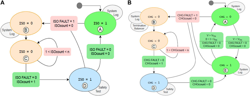
FIGURE 7. (A). Isolation (ISO) control finite state machine, (B). Charging (CHG) control finite state machine.
The finite state machines (FSMs) in Figures 8A, B determine how the BMS handles various combinations of fault conditions. The FSM in Figure 10 also handles charging control. The variables CHG and ISO are the state of the MOSFETs. The variables
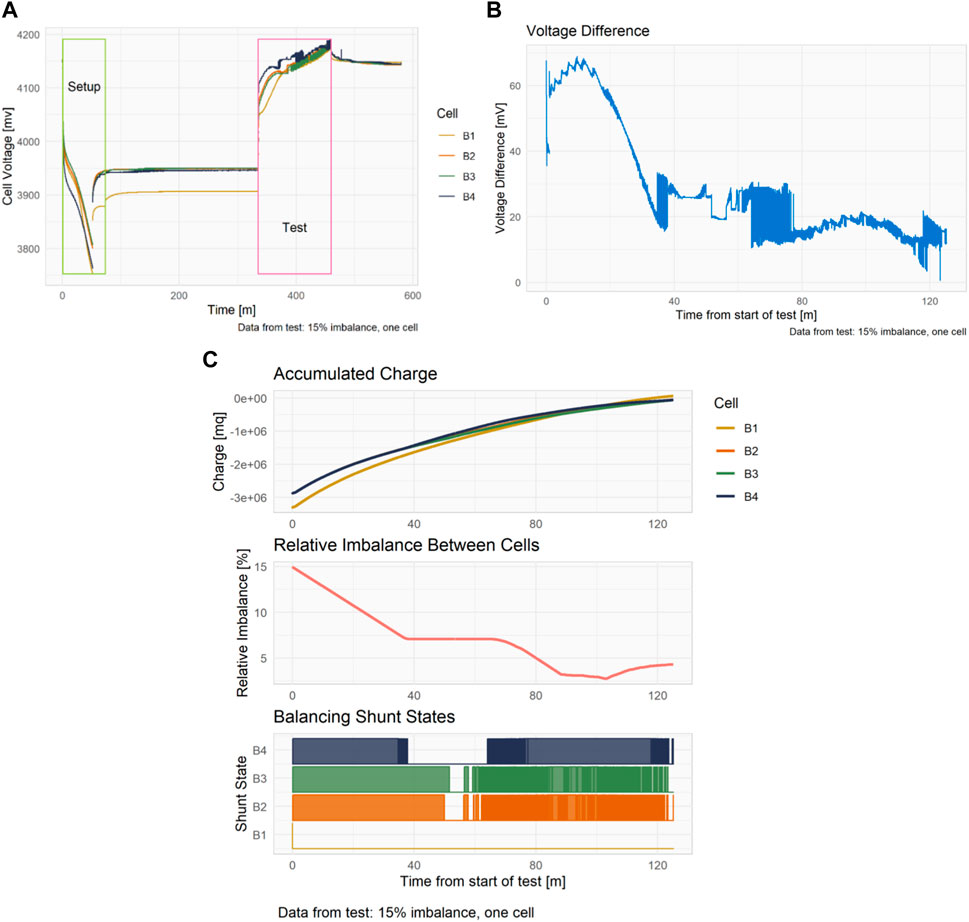
FIGURE 8. (A). Cell voltages during the setup and test phases, (B). Cell voltage difference during test, (C). Accumulated charge, relative imbalance and shunt states during test.
4 Results and discussions
Tests were performed varying the number of cells targeted for unbalancing and varying the relative imbalance. Nine combinations of target cells and relative imbalance were tested: three combinations of cells and three levels of relative imbalance. This gave a cross-sectional view of the performance of the system in mild to extreme cases of imbalance in one or more cells. In each test either one (B1), two (B1 and B2) or three (B1, B2 and B3) cells were targeted for unbalancing. This is similar to the tests performed by [30, 35], but the distribution of imbalance cells is varied across multiple tests, rather than lumped in one test. The target relative imbalance was either 15%, 20% or 30%. A test targeting cell B1 for 15% relative imbalance is shown in Figures 8A, B and C for the purpose of analyzing the details of a test. Figure 8A shows the terminal voltage of each cell for the duration from setup to past test completion where cell B1 was discharged to give a relative imbalance of 15%. For clarity and comparability, the setup and test portions are plotted separately. During the setup period the battery is discharging and the unbalance function is active. After the target imbalance is reached there is a period of rest before the test. During the test the battery is charged. Figure 8B shows the difference in voltage between the highest and lowest voltage cells during the test period in Figure 8A. Most notable is the fact that a voltage imbalance of ∼65 mV was induced and then successfully reduced to 12 mV by the balancing system. The rapid changes in the voltage difference between 35 and 80 min is caused by shunt resistors being switched on and off as the cell voltages converge.
Figure 8C shows the net charge in each cell, the relative imbalance between B1 and the other cells, and the state of each shunt during the test. The accumulated charge is the integral of the current through each cell, for reference,
Figure 9A shows three plots, the voltage of the cells during the charging phase of a test, a highlight of the final section, and the corresponding shunt states for that section. The first plot, Cell Voltage, shows the terminal voltage of all four cells. The lines at 4200 mV and 4150 mV represent the maximum safe voltage and the minimum charged threshold respectively. The second plot, Cell Voltage Highlight, show that when cell B4 reaches the maximum voltage before the battery is fully charged, a fault condition is activated and the charger is disconnected for the cool down period. This fault condition is triggered four times. The exact fault condition caused termination balancer to be called, during the cool down period it applied the shunt resistors to cell B4 to discharge it before charging recommenced. Subsequently, when the third and fourth faults occurred, the other cells had high enough voltages to also require shunting. The third plot, Shunt State, shows in red the periods when a shunt was applied by the termination balancer function. Note that the shunt for cell B4 is on almost continually, unlike those for cells B2 and B3. Both the balancing system and the termination balancer function are attempting to balance the cell. The voltages in Figure 15 contain an interesting staircase-like form. This is a result of the voltage control system in the external charger, not due to any internal resolution limitation of the BMS.
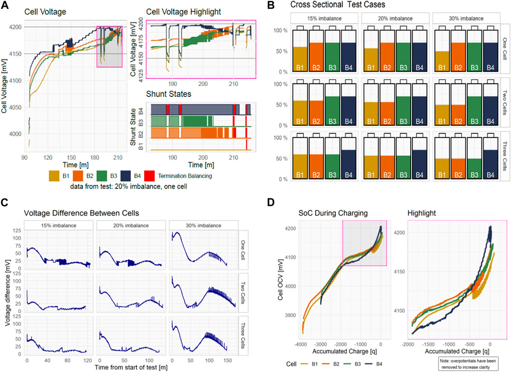
FIGURE 9. (A). Action of the termination balance function, cell voltages and shunt states, (B). Initial cell SOC levels for each test case, (C). Cell voltage difference across all test conditions, (D). State of charge of each cell during test.
The following figures show the results and give a cross sectional view of the performance for all nine cases of target cells and relative imbalances. Each figure contains a small multiple of plots showing all combinations of the two independent variables, number of target cells and relative imbalance. The initial conditions for each test case is shown in Figure 9B, all cells have been discharged, with some more so. Across each row, the plots increase in relative imbalance, and down each column the plots increase in the number of cells targeted by the unbalance function. The plot in Figure 9C shows a similar response for all cases as were seen in the example case in Figure 8B. All nine tests have a peak at the end of discharging which is corrected by the balancing system by the end of charging. The same artefacts from shunts being switched and the non-linear voltage response of LiBs occur in each plot. In the plots for 30% relative imbalance, there was an additional lower peak that occurred half way through charging. The second peak seen in Figure 9C is due to the voltage of one cell rising faster than the others. It is not being charged faster, in fact it is being targeted by the balancing system. The estimated cell OCV is plotted in Figure 9D showing the voltages of all four cells without the influence of charging rate and time. The OCV, as estimated by Lievre’s and discussed in the next chapter, does not change the order of the voltages, but simply removes the large changes in over potentials from shunt switching. Table 1 lists the maximum and final values for the plots in Figure 8C. The maximum voltage difference is of course greater for higher relative imbalances; the final value is also higher. Importantly, the final voltage difference is significantly reduced in all cases. Figure 10A shows the relative imbalance between the cells for each test. All tests show the target imbalance being met and then corrected by the end of charging. Tests with higher relative imbalance have smaller plateaus of imbalance during charging. As discussed, the plateaus are due to periods when the cells voltages are within the tolerance of the balancing algorithm (10 mV). Naturally, this occurs more often with more mild imbalances.
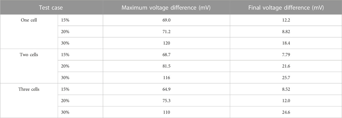
TABLE 1. Maximum and final voltage difference values.
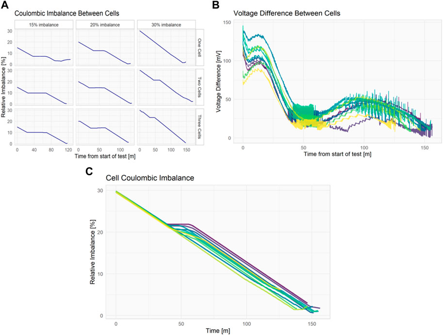
FIGURE 10. (A) Relative imbalance between cells, (B) Cell voltage difference for 10 repetitions of cell B1 with a relative imbalance of 30%, (C) Relative imbalance for 10 repetitions of cell B1 with a relative imbalance of 30%.
The following figures show the results of a single test replicated 10 times to show the repeatability of the results. All test results are shown superimposed, with varying hues of color for each. Replication of the results was conducted under several test conditions, confirming the results. Figure 10B shows the difference between cell voltages during the tests. The initial voltage difference of each test varies by almost 100 mV, but the variation decreases to ∼25 mV by the end of the test. Figure 10C shows practically identical levels of relative imbalance during the discharge phase of the tests, and only minor deviations during the charging phase. Variation in the charging response occurs at 50 min, when the cell voltages in some tests are close enough to not trigger balancing.
5 Conclusion
It has proven effective to use finite state machines in the charging and fault handling of the BMS. The safety and charging systems performed nominally throughout the testing of the BMS. In one instance, the fault condition could not be handled by the simple FSM logic, and it needed to be altered. An under-voltage fault isolates the battery when it is fully discharged. Normally, the MCU and all other systems would shut down in such a situation. The BMS would also isolate the battery if the MCU was still running from external power, such as during testing or when an application required it. The battery voltage would rise above the under voltage threshold when the over potentials from discharge current disappear. This project proposes and verifies a new balancing algorithm. Many analysis techniques had to be developed since passive balancing algorithms are rarely discussed in the literature. There is only one passive balancing algorithm discussed in literature: a method that uses balancing shunts only in the final charging stages. According to the rationale behind the system, charging currents during that final stage are very close to the currents through a shunt, effectively blocking charging for the shunted cells. Cell voltages show battery imbalance, but capacity and state of charge explain it. As a result, the relative imbalance represents the empty, or discharged, capacity for fully charged cells (Wang et al., 2023b).
Data availability statement
The original contributions presented in the study are included in the article/supplementary material, further inquiries can be directed to the corresponding author.
Author contributions
MA-G, Concept, writing. SA, Editing, software. AB, Checking, validation. All authors contributed to the article and approved the submitted version.
Funding
This research project was funded by the Deanship of Scientific Research, Princess Nourah Bint Abdulrahman University, through the Program of Research Project Funding After Publication, grant No (43-PRFA-P-63).
Conflict of interest
The authors declare that the research was conducted in the absence of any commercial or financial relationships that could be construed as a potential conflict of interest.
Publisher’s note
All claims expressed in this article are solely those of the authors and do not necessarily represent those of their affiliated organizations, or those of the publisher, the editors and the reviewers. Any product that may be evaluated in this article, or claim that may be made by its manufacturer, is not guaranteed or endorsed by the publisher.
References
Abdul-jabbar, T. A., Kersten, A., Ali, M., Obed, A. A., Abid, A. J., and Kuder, M. “Efficient battery cell balancing methods for low-voltage applications: A review,” in Proceedings of the 2022 IEEE International Conference in Power Engineering Application (ICPEA), Shah Alam, Malaysia, March 2022, 1–7.
Al-Gabalawy, M., Hosny, N. S., Dawson, J. A., and Omar, A. I. (2021). State of charge estimation of a Li-ion battery based on extended Kalman filtering and sensor bias. Int. J. Energy Res. 45 (5), 6708–6726. doi:10.1002/er.6265
Al-Gabalawy, M., Mostafa, K. M., Darwish, M. M. F., Dawson, J. A., Lehtonen, M., and Hosny, N. S. (2021). Reliable and robust observer for simultaneously estimating state-of-charge and state-of-health of lifepo4 batteries. Appl. Sci. 11 (8), 3609. doi:10.3390/app11083609
Al-Gabalawy, M. N. S. H., and Hussien, S. A. (2020). Lithium-ion battery modeling including degradation based on single-particle approximations. Batteries 6 (3), 37. doi:10.3390/batteries6030037
Al-Gabalawy, M. (2021). Deep analysis of the influence of the different power system structures on the performance of the energy storage systems. Int. J. Energy Res. 45 (12), 17805–17833. doi:10.1002/er.6915
Al-Gabalawy, M. (2021). Reinforcement learning for the optimization of electric vehicle virtual power plants. Int. Trans. Electr. Energy Syst. 31 (8), e12951. doi:10.1002/2050-7038.12951
Assadi, S. A., Gong, Z., Coelho, N., Shawkat Zaman, M., and Olivier, T. (2023). Modular multi-port electric-vehicle DC fast-charge station assisted by a dynamically reconfigurable stationary battery. IEEE Trans. Power Electron. 38 (5), 6212–6223. doi:10.1109/TPEL.2023.3237622
Bhaskar, K. A., Bunce, J., Jacob, P., Burkell, N., and Rahn, C. D. (2023). Data-driven thermal anomaly detection in large battery packs. Batteries 9 (2), 70. doi:10.3390/batteries9020070
Çorapsiz, M. R., and Kahveci, H. (2023). A study on Li-ion battery and supercapacitor design for hybrid energy storage systems. Energy Storage 5 (1), e386. doi:10.1002/est2.386
Gaslov, S. V., Rublev, M. S., Biryukov, A. E., and Kopytov, S. O. (2023). Virtual simulation of the operation of a lithium-ion battery as a part of a vehicle using 1D complex model. Transp. Res. Procedia 68, 906–916. doi:10.1016/j.trpro.2023.02.127
Habib, A. K. M. A., Hasan, M. K., Islam, S., Sharma, R., Hassan, R., Nafi, N., et al. (2022). Energy-efficient system and charge balancing topology for electric vehicle application. Sustain. Energy Technol. Assessments 53, 102516. doi:10.1016/j.seta.2022.102516
Habib, A. K. M. A., and Hasan, M. K. (2023). Lithium-ion battery state-of-charge balancing circuit using single resonant converter for electric vehicle applications. J. Energy Storage 61, 106727. doi:10.1016/j.est.2023.106727
Lee, Yu-L., Lin, C.-H., Farooqui, S. A., Liu, H.-D., and Ahmad, J. (2023). Validation of a balancing model based on master-slave battery management system architecture. Electr. Power Syst. Res. 214, 108835. doi:10.1016/j.epsr.2022.108835
Li, Y., Yin, P., and Chen, J. (2023). Active equalization of lithium-ion battery based on reconfigurable topology. Appl. Sci. 13 (2), 1154. doi:10.3390/app13021154
Schmitt, J., Horstkötter, I., and Bernard, B. (2023). Electrical lithium-ion battery models based on recurrent neural networks: A holistic approach. J. Energy Storage 58, 106461. doi:10.1016/j.est.2022.106461
Shukla, A. P., and Patel, R. A. “Battery management system by passive cell balancing for electric vehicle,” in Proceedings of the 2022 2nd International Conference on Power Electronics & IoT Applications in Renewable Energy and its Control (PARC), Mathura, India, January 2022, 1–6.
Thiagarajan, K., Marabathina, M., MaladhiSelvasundar, D. K., Deepa, T., and Subbulekshmi, D. (2023). “Control of cell voltage difference balancing in battery management system charging circuits in electric vehicles,” in Artificial intelligence applications in battery management systems and routing problems in electric vehicles (Pennsylvania, United States: IGI Global), 56–66.
Turksoy, A., and Ahmet, T. (2023). A fast and energy-efficient nonnegative least square-based optimal active battery balancing control strategy for electric vehicle applications. Energy 262, 125409. doi:10.1016/j.energy.2022.125409
Van, C. N. (2023). Optimal control of active cell balancing for lithium-ion battery pack with constraints on cells’ current and temperature. J. Electrochem. Energy Convers. Storage 20 (1), 011009. doi:10.1115/1.4054530
Vu, H., and Shin, D. (2023). Simultaneous internal heating for balanced temperature and state-of-charge distribution in lithium-ion battery packs. J. Energy Storage 60, 106519. doi:10.1016/j.est.2022.106519
Wang, W., Youssef, A., F., and Preindl, M. (2023). A low cost battery-balancing auxiliary power module with dual active half bridge links and coreless transformers. IEEE Trans. Transp. Electrification, 1. doi:10.1109/TTE.2023.3236610
Wang, Y., and Zhao, G. (2023). A comparative study of fractional-order models for lithium-ion batteries using Runge Kutta optimizer and electrochemical impedance spectroscopy. Control Eng. Pract. 133, 105451. doi:10.1016/j.conengprac.2023.105451
Wang, Y., Xu, H., He, W., Zhao, Y., and Wang, X. (2023). Lattice Boltzmann simulation of the structural degradation of a gas diffusion layer for a proton exchange membrane fuel cell. J. Power Sources 556, 232452. doi:10.1016/j.jpowsour.2022.232452
Wu, T., Chen, L., Xu, Y., and Zhang, X. (2023). Balancing method of retired battery pack based on variable domain fuzzy control. J. Electrochem. Energy Convers. Storage 20 (4), 041005. doi:10.1115/1.4055880
Xu, D., Bai, Z., Wang, T., and Zhuang, W. (2023). A centralized battery energy storage based medium-voltage multi-winding DVC for balance and unbalance operations. IEEE Trans. Industrial Electron., 1–11. doi:10.1109/TIE.2022.3232644
Yun, S.-S., and Kee, S.-C. (2023). Effect of capacity variation in series-connected batteries on aging. Batteries 9 (1), 22. doi:10.3390/batteries9010022
Yun, Z., Qin, W., Shi, W., and Wu, C. (2023). Research on active state of charge balance of battery pack based on two controllable flyback converters. J. Energy Storage 57, 106183. doi:10.1016/j.est.2022.106183
Zhang, H., Tong, X., Zhang, L., and Fu, H. (2023). Fast state-of-charge balancing control strategies for battery energy storage systems to maximize capacity utilization. J. Energy Storage 57, 106269. doi:10.1016/j.est.2022.106269
Glossary

Keywords: battery management system, finite state machin, electric vehicle, cell balancing system, switched resistor
Citation: Hussien SA, BaQais A and Al-Gabalawy M (2023) Battery management system enhancement for lithium-ions battery cells using switched shunt resistor approach based on finite state machine control algorithm. Front. Energy Res. 11:1191579. doi: 10.3389/fenrg.2023.1191579
Received: 22 March 2023; Accepted: 17 May 2023;
Published: 30 May 2023.
Edited by:
Yanzhou Qin, Tianjin University, ChinaReviewed by:
Xiaoyu Li, Shenzhen University, ChinaYulin Wang, Tianjin University of Commerce, China
Zuguo Shen, Wuhan University of Technology, China
Copyright © 2023 Hussien, BaQais and Al-Gabalawy. This is an open-access article distributed under the terms of the Creative Commons Attribution License (CC BY). The use, distribution or reproduction in other forums is permitted, provided the original author(s) and the copyright owner(s) are credited and that the original publication in this journal is cited, in accordance with accepted academic practice. No use, distribution or reproduction is permitted which does not comply with these terms.
*Correspondence: Mostafa Al-Gabalawy, mostafagabalawy@gmail.com