Gas–thermal–solid coupling analysis of a hypersonic inflatable reentry and descent system
 Xu Cao
 Rui Xu1
 - 1School of Aerospace Engineering, Beijing Institute of Technology, Beijing, China
- 2Beijing Institute of Space Mechanics and Electricity, Beijing, China
- 3College of Aerospace Engineering, Nanjing University of Aeronautics and Astronautics, Nanjing, China
Hypersonic reentry has a severe flight environment during spacecraft return. To analyze the influence of pneumatic loads on the flexible structure under the extreme load condition during the deceleration process of inflatable reentry and descent system, fluid–and thermal–solid couplings have been studied. In addition, the stress and structural deformation distributions and the temperature distribution of each functional layer of the flexible thermal protection system were obtained in this study. The influence of flight conditions and structural parameter changes on inflatable structure performance was studied, and the transient response mechanism of the pneumatic load to the inflatable structure was revealed. Ballistic analysis combined with engineering algorithm was used to predicted the flight envelope. The fluid-solid thermal coupling method in Workbench is utilized to realize the real-time transfer of aerodynamic and thermal loads to flexible structures. And the loose coupling method was applied to carried out the one-way transfer of aerodynamic load and thermal load to the surface of flexible structure. The results showed that the mechanical–thermal–structural coupling analysis method could predict the mechanical properties of flexible inflatable deceleration structures, which can provide references for the aerodynamic configuration and thermal protection design under extreme flight conditions.
1 Introduction
Inflatable reentry and descent technology (IRDT) is becoming more important as the number of space activities and deep-space exploration projects increases and payload recovery problems of different sizes and masses and rover entry problems on other planets occur. Among them, the inflatable reentry vehicle experiment (IRVE) of the United States of America and Russia’s inflatable reentry and decent technology are representative. Although the inflatable reentry and descent system is still far from practical application, its feasibility has been verified by several flight tests. Aerodynamic deceleration and thermal protection are key technologies used in the inflatable reentry and descent system. Aerodynamic thermal effects during hypersonic deceleration can cause structural damage and material property change. Concurrently, under high aerodynamic force and aerodynamic thermal load, the inflatable structure deforms significantly. This leads to shape-changing, resulting in aerodynamic force variation and aerodynamic thermal load again, thus affecting the deceleration performance. This problem is a typical multi-physical field coupling analysis problem. To ensure safety during hypersonic reentry deceleration, it is necessary to study the inflatable structure performance under the coupling effect of aerodynamic and thermal loads. Considering the feasibility, cost, and time of wind tunnel tests, numerical simulation has become the main research method.
The inflatable reentry and descent system, with flexible thermal protection system by innovated ceramic fiber and nanostructured insulating felt (Karlsson and Kohara, 2022), (Singh et al., 2022), has the ability of aerodynamic deceleration and thermal protection in high-speed reentry processes and has broad application prospects in the fields of planetary exploration, space cargo recovery, and near-space hypersonic vehicle return (Marraffa et al., 2000), (Marraffa et al., 2003), (Wilde et al., 2002). Different from traditional reentry aircraft, the dynamic characteristics of a flexible inflatable structure show strong non-linear characteristics. Therefore, accurate prediction of its aerodynamic and dynamic characteristics is an important prerequisite for system design. Since the 1980s, there has been significant research on hypersonic thermal–fluid–structure coupling.
Litton (Litton et al., 2011) used the finite element method to analyze the structural dynamic characteristics of an inflatable reentry vehicle IRVE-4 and studied the non-linear structural deformation of a flexible inflatable structure under different inflation pressures. In finite element numerical modeling, Kinney (Kinney, 2011) simplified the flexible inflatable membrane into two element types: tension spring and bending spring, performed a steady-state and transient structural dynamic analysis, and predicted the changes associated with surface buckling and annular pressure of the inflatable structure. Li (Li et al., 2015) studied transient structural dynamics based on the non-linear finite element theory and analyzed the transient response, stress, and strain distribution of a flexible inflatable structure under given aerodynamic forces; however, the accuracy of the numerical model still required verification through experiments. Liu (Liu and He, 2015) used the finite element method to analyze the influence of material non-linearity on the natural vibration characteristics of an inflatable ring and concluded that the increases in internal pressure and flexible-film thickness could reduce the natural frequency of a flexible inflatable structure. Zhang (Zhang et al., 2018) applied the computational fluid dynamics (CFD) method to simulate the flow field and surface heat flow distribution around flexible inflatable structures of different reentry heights. In addition, the author established the finite element model and studied the effects of material non-linear factors such as inflation pressure and film thickness on static and modal characteristics. McNamara (McNamara et al., 2008) solved the aerodynamic heat problem using the CFD method combined with the finite element method and studied heat conduction between the hypersonic flow and structure. Li (Li et al., 2008) introduced different temperature distributions obtained from aerodynamic thermal and heat transfer calculations into the calculation of structural dynamic thermal stiffness to investigate the thermo-aeroelasticity of a hypersonic aircraft wing surface. Lv (Lv et al., 2010) studied the thermo-aeroelasticity of a hypersonic vehicle by taking the aerodynamic heat and heat transfer analyses results as the load boundary conditions of the thermo-aeroelasticity analysis. Suman (Muppidi et al., 2015) analyzed the aerodynamic thermal load of an inflatable reentry structure based on the CFD method and studied the membrane thermodynamic response, which was subsequently compared with the flight tests. Wang (Wang et al., 2015) used the CFD method to study aerodynamic deceleration performance, aerodynamic thermal load, and plane trajectory of an inflatable reentry and descent system. Furthermore, the author discussed the effects of the reentry angle and geometric cone angle on the aerodynamic and thermal performance of the inflatable structure. Without considering the heat transfer structure, Rong (Rong et al., 2015) simulated the stagnation point heat flux and surface temperature distribution of the inflatable structure under typical working conditions based on the CFD method. Huang (Huang and Wang, 2016a), (Huang and Wang, 2016b) established a heat transfer model of a flexible thermal protection system (TPS), analyzed the thermal response of the multifunctional laminated layer using the finite element method, and proposed the shape configuration and thermal protection optimization design strategy.
The thermal–fluid–solid coupling analysis of a flexible structure is complex; if the tight coupling method is used, then the geometric and material non-linearity and the complex hypersonic flow field and temperature field calculation have to be included as well, which is difficult and costly. Currently, research on using the tight coupling method to study the large deformation thermal–fluid–solid coupling problem is lacking. In this study, to analyze the influence of aerodynamic heat and force on structural performance during the high-speed reentry process of an inflatable reentry and descent system, the coupling performance under extreme working conditions was studied using the loose coupling analysis method. The findings can provide a reference for the design of an inflatable structure and system performance analysis. In previous studies, the thermal load of flexible structures was usually constant, variations of surface temperature and heat flow distribution due to the deformation of the structure under aerodynamic load were not taken into account. In this paper, the fluid-solid thermal coupling method based on Workbench platform is used to realize the real-time transfer of aerodynamic and thermal loads to flexible structures. Firstly, the flight envelope during the loading process of the inflatable structure is predicted by ballistic analysis and engineering algorithm, simultaneously the aerodynamic and thermal loads under extreme working conditions are roughly obtained. Then, the Fluent solver is used to calculate the aerodynamic and aerothermal load under extreme working conditions finely, and the pressure and thermal stress distribution data are transferred to the finite element model of the flexible structure by loosely coupling. The dynamic response of the structure under the action of aerodynamic thermal coupling is finally obtained.
2 Mathematical modeling of hypersonic reentry process with flexible inflatable structures
When the payload body enters and passes through the atmosphere at high speed (Figure 1), the intense aerodynamic heating effect results in a large amount of heat conduction to the surface of the payload body, causing its surface temperature to rise sharply. Preventing the structural strength of the payload body from weakening and causing structural damage owing to the high temperature rise is an important research area in the process of spacecraft entry and return. The hypersonic flexible inflatable reentry structure is composed of a stacked ring structure and rigid head cone, which is an inverted cone structure as a whole. In the reentry process, the head cone is subjected to high-speed flow and relies on the inflatable ring structure to provide aerodynamic resistance and thermal protection. The payload capsule can be inflated several times as required during descent to increase the windward resistance area and finally land at a safe landing speed or splash down in the ocean.
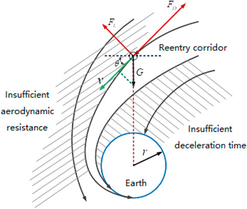
FIGURE 1. Schematic diagram of loading body entering deceleration and landing process.
Because of the hypersonic reentry into the atmosphere, the outer surface of the structure must resist the high temperature of the thermal boundary layer, which is typically above 1000 °C. Therefore, flexible thermal shielding is an important component of flexible inflatable structures. A flexible TPS is a laminated multifunctional structure composed of thermal insulation, insulation, and airtight layers. The system is required to withstand high temperatures and should have low density and flexible folding characteristics. The component material parameters of the inflatable structure are shown in Table 1.
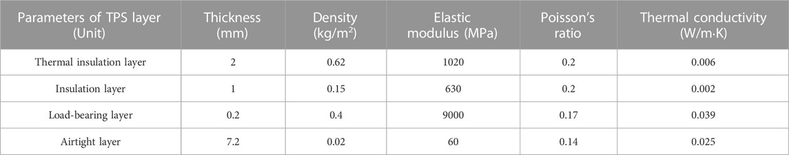
TABLE 1. Structural and material parameters of the inflatable structure.
2.1 Reentry trajectory and engineering thermal analysis model
For reentry deceleration of an inflatable structure, characteristics of the gas–heat–soft-solid coupling problem should be considered during the flight process; therefore, the pneumatic heat, temperature distribution, and thermal load and deformation are studied. The premise of the abovementioned coupling analysis is to accurately obtain the ballistic characteristics of the deceleration system of the payload body during the deceleration process and extract the extreme conditions of the aerodynamic and thermal loads. The following assumptions are introduced in the deceleration ballistic analysis process: 1) the lateral force is ignored, and the system is considered to fly in a two-dimensional plane; 2) the effect of the Earth’s rotation is negligible; 3) the influence of the meteorological wind field is negligible; 4) the aerodynamic shape remains unchanged during reentry; 5) during the reentry process, the attack angle is constantly zero, that is, the central axis of the reentry capsule or the connecting line of the parachute system always coincides with the incoming flow direction and is only subjected to aerodynamic resistance. The flight dynamics control equation of the loading body during entry is shown in Eq. 1.
where m is the reentry mass; v is the flight speed of the reentry; θ is the local ballistic inclination; t is the flight time; r is the distance from the center of the Earth; x is the horizontal displacement, h is the altitude from the ground; FL and FD are lift force and resistance, respectively; ρ is atmospheric density; CA is the equivalent resistance area of the recovery system. The fourth-order Runge–Kutta algorithm was used to calculate the integral of the dynamic process. Atmospheric parameters were calculated using the 1976 American standard atmospheric model.
First, the variation curves of height–velocity, height–overload, and heat flux during the reentry process were rapidly analyzed using an engineering algorithm, and the temperature distribution law of the thermal protection structure was studied. According to the numerical results, the state points of the maximum aerodynamic load and maximum aerodynamic thermal load were obtained. The aerodynamic heat calculation included aerodynamic heat at stagnation and non-stagnation points, and the calculation models used were the Kemp–Riddell and Lees heat flux density distribution formulae, respectively. The following equation is the mathematical model used in the engineering calculation:
In the above formula,
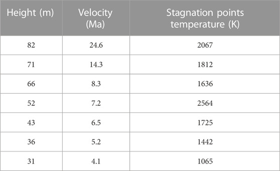
TABLE 2. Stagnation point temperature and heat flux at different altitudes and Mach numbers.
The rigid hemispherical head cone is obtained according to isentropic outflow conditions and the modified Newtonian pressure distribution theory, and the calculation formula is as follows:
where qwb is the heat flow at the stagnation point of the head of the sphere, and
In addition, the surface heat flux of the flexible inflatable vertebral body was obtained according to the isentropic outflow conditions and modified Newtonian pressure distribution theory. The calculation formula is as follows:
In the above formula,
In the reentry process, the transition time of the wall surface from a non-steady state to a steady state is very short and can be considered negligible. Meanwhile, the influence of the Earth’s radiant heat and other minor terms are neglected to establish the heat balance equation, as follows:
2.2 Compressible aerothermal analysis model
In this study, the maximum flight speed of the flexible inflatable structure in the reentry process is above Ma20, and the compression and high temperature effects of the gas cannot be ignored. For a compressible fluid, the basic form of the conservative three-dimensional compressible Navier–Stokes equation is shown in Eq. 7:
where
where
2.3 Gas–thermal–solid coupling analysis model
Flexible inflatable structures have severe gas–thermal and solid bidirectional coupling problems under hypersonic flows. Large mesh deformation can occur with ease during the coupling process, resulting in a negative volume that leads to calculation failure. Therefore, the fluid–structure coupling of the flexible structure is a common complex problem in the field of fluid–structure coupling. In this study, a spatiotemporal discrete finite element numerical analysis method is used to study the multi-field coupling of an inflatable decelerator under extreme working conditions, and the ANSYS Workbench platform is used to perform loose gas–thermal–solid multi-field coupling analysis. The calculation and data transfer processes are shown in Figure 2.
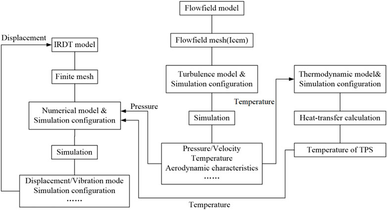
FIGURE 2. Flow chart of coupling analysis and data transfer.
3 Numerical analysis method validation
3.1 Validation of flow field analysis method
To verify the accuracy of the flow field calculation of flexible inflatable structures at supersonic speed, numerical tests were performed for supersonic and hypersonic conditions, and the optimal mesh and turbulence models were determined. The numerical simulation results show that the model is more accurate at low Mach numbers and high supersonic speeds. Figure 3 compares the velocity distribution of the flow field under Ma2with that of the wind tunnel test. Figure 4 shows the velocity and pressure cloud diagrams of the symmetric section of the flow field under Ma2, Ma4.6, and Ma22. It can be seen that the flow field diagrams of the numerical calculation are in good agreement with those of the wind tunnel test.
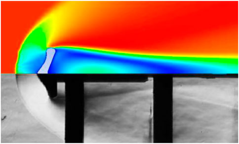
FIGURE 3. Comparison with Ma2 wind tunnel test results.
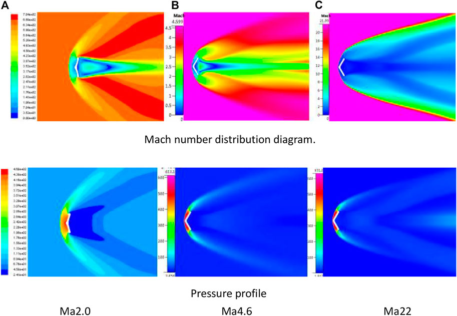
FIGURE 4. Velocity and pressure distribution of the symmetrical surface of the flow field under different Mach conditions (upper: Mach number, lower: pressure).
Table 3 shows the comparison of the numerical calculation results with literature and engineering formula at supersonic speeds. It can be seen that the resistance coefficient calculation and stagnation point temperature are relatively accurate, and the heat flux density error is large. The reasons for heat flux error are as follows:
(1) There exist errors in the aerothermal calculation of the existing engineering formulas.
(2) The numerical calculation in this study does not consider the gas parameter changes caused by high temperature.
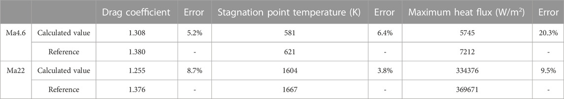
TABLE 3. Flow field analysis verification results statistics.
3.2 Validation of coupling analysis methods
To verify the rationality of the single fluid–solid coupling method in this study, a verification analysis was conducted on the object and research condition considered in reference (Yang et al., 2014). The verification object is the inflatable wing of a small unmanned aerial vehicle with an NACA4412 section, 0.6 m half-wingspan, and 0.25 m chord length (as shown in Figure 5). The pressure difference between the inner and outer surfaces of the wings is 45 kPa. The material parameters of the inflatable wing are shown in Table 4. The flight speed and angle of attack were 15 m/s and 10°, respectively.
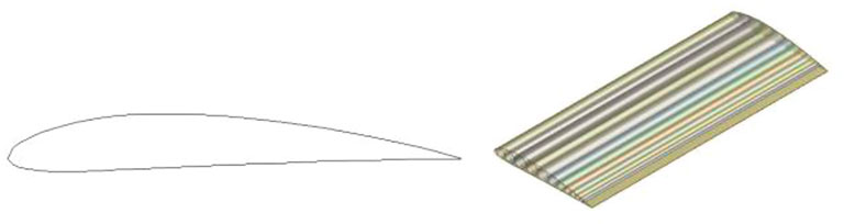
FIGURE 5. NACA4412 airfoil section and 3D model schematic diagram.

TABLE 4. Material parameters of inflatable wing.
Figure 5 shows the flow field and structural grid models established for the flexible inflatable wing. The flow field adopts a structural grid with a total number of 880,000 units. The wing surfaces are composed of 25147 triangular thin film elements. The coupling calculation is performed by one-way aerodynamic loading in the flow field, whereas in the literature, it is performed by multiple iterations of aerodynamic loading and two-way loading of structural deformation. A comparison of the calculation results of the two methods is shown in Figure 6, and the numerical calculation results in this study are consistent with the results obtained in the literature. The maximum displacement of the wing tip obtained using the method proposed in this study was 19.21 mm, whereas 18.56 mm was obtained for the literature, and the maximum displacement error of the two was 3.5%. The abovementioned results show that the unidirectional fluid–structure coupling method adopted in this study has high accuracy. The above mentioned results show that the coupling analysis method adopted in this paper is highly consistent with the calculation of airfoil deformation compared with the literature, and has a higher resolution for the surface displacement distribution.
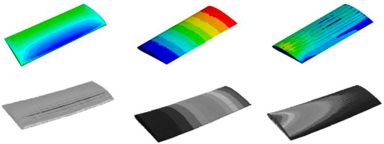
FIGURE 6. Comparison of coupling analysis results (top: method in this study, bottom: literature).
4 Gas–thermal–solid coupling analysis of flexible inflatable structures
4.1 Multi-field coupling analysis modeling of hypersonic reentry process
Hypersonic fluid–thermal–solid coupling consists of the solution of gas–thermal–solid coupling in three fields. The calculation model is shown in Figure 7. The blunt part adopts a rigid structure, whereas the cone part adopts a flexible structure with inflatable expansion. The difficulty of multi-field coupling lies in the information transfer between the physical fields. Based on the ANSYS Workbench platform, this study conducted research on the thermal–fluid–structure coupling of the flexible inflatable unfolding structure. Figures 8, 9 show the flow field and numerical models of the flexible inflatable structure established in this study. The flow field is a cylindrical structured grid, and the parameters used for flow field calculation are shown in Figure 8. The flow field size is
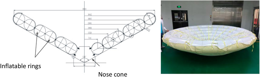
FIGURE 7. Schematic diagram of deployable aerodynamic dissymmetric section and expansion state.

FIGURE 8. Flow field model and grid.
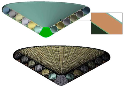
FIGURE 9. 3D model and grid of the flexible inflatable structure.

TABLE 5. Calculation working conditions of gas–thermal–solid coupling.
4.2 Analysis of aerodynamic thermal numerical simulation results
Figure 10 shows the surface pressure cloud diagram of the flow field of the flexible inflatable structure under two working conditions, and Figure 11 shows the flow velocity diagram around the symmetric surface of the flexible inflatable structure under two working conditions. As can be seen from the figure, the front shock wave moved backward significantly at hypersonic speed, resulting in the loss of the expansion and recompression waves in the flow field, and the maximum pressure was identified behind the front shock wave. Part of the high-speed incoming gas forms a stagnation point at the blunt head. The other part passes through the shoulder of the flexible inflatable structure to form a free shear layer, which forms a negative pressure reflux zone on the leeward side. At the stagnation point on the windward side of the flexible inflatable structure, the temperature is higher than that in other areas of the flow field. Under the two working conditions, the cloud diagram of pressure and temperature distributions on the windward surface is shown in Figure 10. The pressure and temperature distribution curves along the meridional surface are shown in Figure 11. As can be seen from the figure, the pressure and temperature on the windward side are higher than those on the leeward side. Furthermore, the pressure and temperature at the stagnation point of the blunt head were the highest. In addition, the pressure distributions of the windward and leeward sides of the flexible structure are uniform. The temperature on the leeward side gradually decreased along the meridian direction, whereas the temperature on the leeward side was evenly distributed.
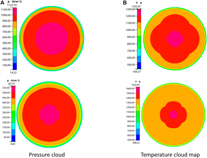
FIGURE 10. Cloud diagram of the pressure and temperature distribution on the windward side of the flexible inflatable structure. (A) Pressure cloud map (B)Temperature cloud map
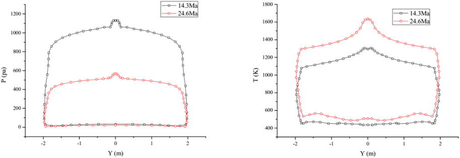
FIGURE 11. Meridional pressure and temperature distribution curves of flexible inflatable structure.
4.3 Deformation and vibration modal analysis of flexible structures
In this study, the inertial release method was used to analyze the deformation and dynamic characteristics of the flexible inflatable structure under two extreme working conditions, as shown in Table 4. The inflatable tube pressure was set to 150 kPa during the calculation. The structure shape and stress of the flexible structure under aerodynamic and thermal loads were investigated using gas–thermo–solid coupling analysis. Furthermore, to obtain the transient response variation of flexible inflatable structures under extreme aerodynamic loads, numerical simulation was performed under extreme thermal loads (82 km–Ma24.6) based on the LS-DYNA multi-physical field coupling analysis platform.
Figures 12, 13 show the normalized strain-stress distribution curves of the meridian coordinates of each functional layer under the flight condition of Ma24.6. It can be seen that the stress concentration occurred in the contact position between the TPS layer and blunt head, and the TPS stress changes in the three layers were consistent. When the TPS layer was subjected to external aerodynamic load, the two rings collapsed (as shown in Figure 14), resulting in wavy stress distribution in the TPS layer.
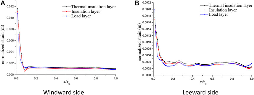
FIGURE 12. Variation curve of TPS multifunctional layer strain with thickness direction. (A) Windward side (B) Leeward side
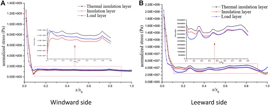
FIGURE 13. Stress distribution in each functional layer of the TPS. (A) Windward side (B) Leeward side
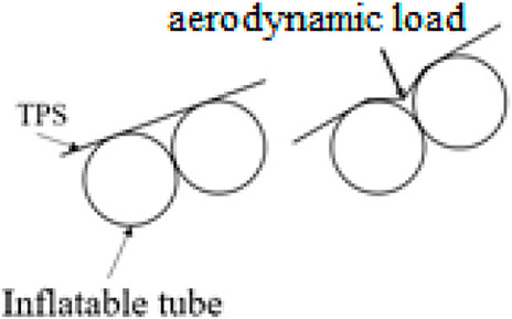
FIGURE 14. Schematic diagram of local collapse of TPS layer caused by aerodynamic load.
Figure 15 shows the stress distribution of each inflatable ring along the circumference of the ring. Because of the similar material used in the six-ring inflatable circular tube, the stress-strain variation law was consistent under the isotropic assumption, in which the 0.1–0.6 m part is in the leeward side, and the 0–0.1 m and 0.6–1.05 m parts are in the windward side.
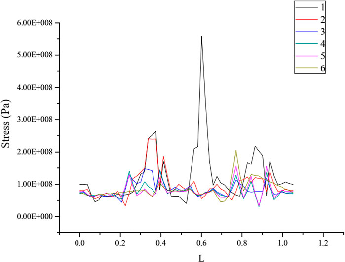
FIGURE 15. Circumferential stress distribution of cross sections of each ring.
Table 6 lists the typical vibration modes and the vibration modes of the flexible inflatable structure under aerodynamic and thermal loads. In addition, its vibration modes under Ma14.3 flight conditions are shown in Figure 16. It can be seen that under Ma14.3, the flexible inflatable structure has three modes, namely, expansion, swing, and torsion, whereas, under Ma24.6, the flexible inflatable structure has two modes, namely, swing and torsion. Under the two working conditions, the vibration frequency of the flexible inflatable structure was approximately 80 Hz in the swing mode and approximately 151 Hz in the torsion mode. The vibration frequency of the flexible inflatable structure decreased slightly owing to the increased aerodynamic heat at Ma24.6. The transient vibration of the flexible inflatable structure is mainly because of the pressure inside the balloon owing to the external dynamic pressure, which is lower than the pressure inside the balloon. In addition, the external pressure and thermal load acting on the TPS layer have an insignificant influence on the system vibration. The sixth ring has the largest form variable owing to fewer constraints. In addition, because of the constrained extrusion effect of the rigid structure, the rigid-flexible joint stress of the first ring is the largest, reaching 0.107 GPa, which is far less than the tensile strength of the material of 3.6 GPa.
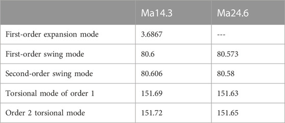
TABLE 6. Vibration modes of various orders of flexible inflatable structure (unit: Hz).

FIGURE 16. Typical modes of the flexible inflatable structure. (A) Scaling (B) Swing (C) Torsion
Figure 17 shows the transient displacement and equivalent stress distribution of the thermal insulation layer and flexible structure of each ring under the combined action of the external aerodynamic force, heat, and internal pressure of the inflatable ring. Under the TPS constraints and binding, the stability time of the flexible structure was approximately 2.5 s. The stress value of the ring is higher than that of other structure parts, and the amplitude attenuation was clearly under the binding and TPS constraints.
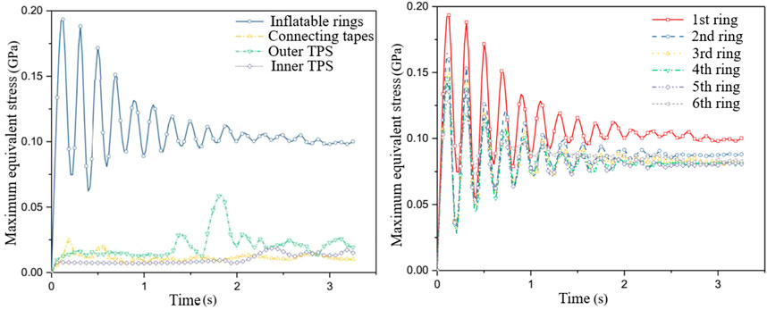
FIGURE 17. Transient displacement and equivalent stress distribution of flexible structure under internal and external aerodynamic and thermal loads.
5 Conclusion
In this study, based on the design scheme of the flexible inflatable expandable aerodynamic deceleration and thermal protection structure and the reentry and return process, a gas–thermal–solid coupling numerical calculation model was established. In addition, the dynamic and static mechanical response characteristics of the flexible inflatable structure under hypersonic extreme conditions were obtained. The transient response of extreme aerodynamic loads to flexible structures was analyzed based on the LS-DYNA multi-physical field coupling analysis platform. The conclusions are as follows:
With the increase in flight Mach number, the front shock wave significantly shifted backward, resulting in the loss of the expansion and recompression waves in the flow field. At the stagnation point, on the windward side of the flexible inflatable structure, the temperature is higher than that in other flow field areas. The pressure and temperature on the windward side of the flexible inflatable structure are higher than those on the leeward side. The temperature on the windward side gradually decreases along the meridian direction, whereas for the leeward side, it is evenly distributed.
In the process of coupling calculation solving, due to the obvious difference in the time step requirements of flexible structure and flow field stability solution, the flow field calculation adopts an implicit algorithm, and the solution stability is not sensitive to the timestep, while the flexible structure finite element calculation requires a timestep less than 0.05 ms, so in this paper the timestep of flexible-structure solution was configured carefully to achieve stable progress during the solution.
The flexible inflatable structure can maintain a good aerodynamic shape under extreme aerodynamic heat and aerodynamic force. In the rigid and flexible contact parts, because of the large difference in material properties, there will be significant deformation, resulting in the maximum stress of the TPS functional layer at the blunt joint and the maximum stress of the inflatable ring at the first ring; however, all meet the material strength requirements.
The aerodynamic heat and aerodynamic force of the windward and leeward sides of the flexible inflatable structure are different, and the stress and strain of the windward and leeward sides are different. The modes of the flexible inflatable structure are expansion, swing, and torsion modes. Aerodynamic force and heat have an insignificant influence on the modal characteristics of the flexible inflatable structure.
Data availability statement
The original contributions presented in the study are included in the article/supplementary material, further inquiries can be directed to the corresponding author.
Author contributions
Conceptualization, CX, XR, and YL; Methodology and software, ZX and WQ; Writing—original draft preparation, CX; Writing—review and editing, WQ; All authors have read and agreed to the published version of the manuscript.
Conflict of interest
The authors declare that the research was conducted in the absence of any commercial or financial relationships that could be construed as a potential conflict of interest.
Publisher’s note
All claims expressed in this article are solely those of the authors and do not necessarily represent those of their affiliated organizations, or those of the publisher, the editors and the reviewers. Any product that may be evaluated in this article, or claim that may be made by its manufacturer, is not guaranteed or endorsed by the publisher.
References
Huang, M. X., and Wang, W. Z. (2016). A study on heat flux and structure of inflatable reentry thermal protection system. Spacecr. Eng. 25 (1), 52–59.
Huang, M. X., and Wang, W. Z. (2016). Optimization on a flexible thermal protection structure of inflatable reentry system. Spacecr. Recovery & Remote Sens. 37 (1), 22–31.
Karlsson, S., and Kohara, S. (2022). Editorial: Innovators in ceramics and glass. Front. Mat. 9, 1079681. doi:10.3389/fmats.2022.1079681
Kinney, D. “Prediction of fluid-surface interactions and aerothermal environments using CBAERO,” in Proceedings of the 49th AIAA Aerospace Sciences Meeting including the New Horizons Forum and Aerospace Exposition, Orlando, Florida, January 2011, 1186.
Li, L., Gonyea, K., and Braun, R. D. “Finite element analysis of the inflatable re-Entry vehicle experiment (IRVE),” in Proceedings of the 56th AIAA/ASCE/AHS/ASC Structures, Structural Dynamics, and Materials Conference, Kissimmee, Florida, January 2015, 0204.
Li, Z. W., Lin, L. J., and Guan, S. Y. (2008). Research on the thermal flutter characteristics of hypersonic all-move wing. Tactical Missile Technol. (5), 36–39.
Litton, D., Bose, D., Cheatwood, F., Hughes, S, Wright, H, Lindell, M, Derry, S, and Olds, A. “Inflatable re-entry vehicle experiment (IRVE)-4 overview,” in Proceedings of the//21st AIAA Aerodynamic Decelerator Systems Technology Conference and Seminar, Dublin, Ireland, May 2011, 2580.
Liu, F., and He, W. L. (2015). Numerical simulation of space inflatable torus dynamic behavior. Comput. Simul. 32 (3), 123–126.
Lv, J. H., Yang, M., and Chen, F. M. (2010). Aero-thermoelastic simulation of supersonic missile rudder. Comput. Simul. 27 (3), 43–46.
Marraffa, L., Kassing, D., Baglioni, P., Wilde, D, Walther, S, Pitchkhadze, K, and Finchenko, V S. (2000). Inflatable re-entry technologies: Flight demonstration and future prospects. ESA Bull. 2000 (103), 78–85.
Marraffa, L., Vennemann, D., Anschuetz, U., Walther, S., Stelter, C. S., and Pitchkhadze, K. M. (2003). IRDT-Inflatable re-entry and descent technology[C]//Hot Structures and Thermal Protection. Syst. Space Veh. 521, 19.
McNamara, J., Friedmann, P., Powell, K. G., Thuruthimattam, B. J., and Bartels, R. E. (2008). Aeroelastic and aerothermoelastic behavior in hypersonic flow. AIAA J. 46 (10), 2591–2610. doi:10.2514/1.36711
Muppidi, S., Tanimoto, R., Bose, D., Tang, C., and Clark, I. G. “Aerothermal environment and thermal response of supersonic inflatable decelerators,” in Proceedings of the 53rd AIAA Aerospace Sciences Meeting, Kissimmee, United States, January 2015.
Rong, C., Zuo, G., Chen, C., Yushuo, H. E., Guo, B., and Shi, Y. (2015). A study of general scheme and key technologies of inflatable re-entry vehicle. Spacecr. Recovery & Remote Sens. 36 (1), 16–23.
Singh, S. P., Li, M., and Fecht, H. J. (2022). Editorial: Nanostructured glass: Properties and applications. Front. Mater 9, 869266. doi:10.3389/fmats.2022.869266
Wang, R., Hou, A., and Niu, Y. “The optimal design and analysis of the IRDT system based on two-dimensional ballistic trajectory in atmosphere reentry,” in Proceedings of the 20th AIAA International Space Planes and Hypersonic Systems and Technologies Conference, Glasgow, Scotland, July 2015.
Wilde, D., Walther, S., Pitchadze, K., Alexsaschkin, S., Vennemann, D., and Marraffa, L. (2002). Flight test and ISS application of the inflatable reentry and descent technology (IRDT). Acta Astronaut. 51 (1-9), 83–88. doi:10.1016/s0094-5765(02)00078-4
Yang, Y., Ma, Y., and Wu, Z. (2014). Analysis of effect of interior pressure to deformation of inflatable wing with fluid-structure interaction analysis method. J. Beijing Univ. Aeronautics Astronautics 40 (2), 188–192. (in Chinese).
Keywords: hypersonic, flexible inflatable deceleration structure, reentry, mechanical-thermalstructural coupling analysis, inflatable reentry and descent system
Citation: Cao X, Xu R, Yu L, Zhao X and Wang Q (2023) Gas–thermal–solid coupling analysis of a hypersonic inflatable reentry and descent system. Front. Mater. 10:1150320. doi: 10.3389/fmats.2023.1150320
Received: 24 January 2023; Accepted: 27 February 2023;
Published: 14 March 2023.
Edited by:
Lik-Ho Tam, Beihang University, ChinaCopyright © 2023 Cao, Xu, Yu, Zhao and Wang. This is an open-access article distributed under the terms of the Creative Commons Attribution License (CC BY). The use, distribution or reproduction in other forums is permitted, provided the original author(s) and the copyright owner(s) are credited and that the original publication in this journal is cited, in accordance with accepted academic practice. No use, distribution or reproduction is permitted which does not comply with these terms.
*Correspondence: Xu Cao, caoxu16@126.com