A high resolution γ-ray array for the pandora plasma trap
 A. Goasduff1
  D. Santonocito2*
  R. Menegazzo3
  S. Capra4,5
  A. Pullia4,5
  W. Raniero1
  D. Rosso1
  N. Toniolo1
  L. Zago1,6
  E. Naselli2
  D. R. Napoli1
- 1Laboratori Nazionali di Legnaro, INFN, Legnaro, Italy
- 2Laboratori Nazionali del Sud, INFN, Catania, Italy
- 3Sezione di Padova, INFN, Padova, Italy
- 4Dipartimento di Fisica, Università degli Studi di Milano, Milano, Italy
- 5Sezione di Milano, INFN, Milano, Italy
- 6Dipartimento di Fisica e Astronomia, Università degli Studi di Padova, Padova, Italy
The measurement of β-decay rates in plasma, simulating stellar-like conditions, is of high interest for the investigation of radionuclides involved in nuclear astrophysics processes. In the new PANDORA plasma trap, to be built at the INFN—Laboratori Nazionali del Sud of Catania (Italy), the β-decay rates will be estimated by detecting the γ-rays emitted by the daughter nuclei trapped in the confined plasma. The present work describes the high efficiency High Purity Germanium (HPGe) detector array that will be placed around the magnetic trap for this purpose, as well as the front-end electronics and acquisition system suitable for the array operation in presence of a high counting rate background originating from Bremsstrahlung radiation.
1 Introduction
The PANDORA (Plasma for Astrophysics Nuclear Decay Observation and Radiation for Archaeometry) experiment aims to develop a totally new approach to measure, for the first time, nuclear β-decay rates in a plasma simulating stellar-like conditions. To achieve this task a dedicated compact plasma trap will be built at the INFN—Laboratori Nazionali del Sud of Catania and will be used to run experiments in the forthcoming years.
The basic idea of the experiment is to gain some knowledge on weak interactions in s-process nucleosynthesis environments and is motivated by some theoretical predictions and experimental evidences showing that β-decay properties of radioactive nuclei can be strongly affected by the electron densities. In particular, highly ionized nuclides can display important variations in β-decay rates due to the opening of the bound state β-decay channel [1], an effect observed in few experiments performed using storage rings [2, 3]. The importance of this decay channel has to be clearly elucidated since it could have a major impact in astrophysical scenarios as s-process nucleosynthesis, where the competition between neutron capture and β-decay plays a major role in the synthesis of the elements. Only few experimental evidences showing variations in the β-decay rates as a function of the atomic fully-ionization state have been collected up to now (using mainly storage rings); thus, the new experimental method proposed by PANDORA can shade new light on the role of weak interaction on the stellar nucleosynthesis.
This new approach, based on the study of decays rates in a laboratory magneto-plasma confined in a compact plasma trap, aims to carry out measurements in which the decaying ions display a charge state distribution resembling the one present in the hot stellar environment (or that can be properly scaled to it).
Plasma parameters will be inferred using dedicated non-invasive diagnostic tools [4] and the nuclear decay rates will be evaluated as a function of the charge state distribution of in-plasma ions [5].
In order to measure the β-decay rates with high efficiency, it is necessary to install around the magnetic trap an array of γ detectors, which will allow for the identification of β-decaying nuclei by measuring the energy of the γ-rays emitted by the daughter nuclei. High-resolution spectroscopy of ions within a trapping volume is challenging, with limited examples in the literature (e.g., [6]).
In the following, we will describe the high resolution detector array that will be placed around the trap with its dedicated electronics, acquisition system and infrastructure that will allow the γ-ray detector array operations during the relatively long measurement runs needed for each experimental campaign.
2 The gamma array
The γ-ray detector array of PANDORA plays an important role in the project. It will be used to measure the in-plasma decay rate of selected radionuclides, β emitters, through the detection of the γ-rays emitted by the daughter nuclei [7]. If the concentration of the radioisotope is kept in dynamical equilibrium in the plasma through a proper balance between plasma losses due to the finite confinement time of the ions and the amount injected in the trap, the measured decay rate dN/dt will depend on the product λ ⋅ ni ⋅ V where λ is the radioactive decay constant, ni is the density of the radioactive ions in the plasma and V is the plasma volume. Since the plasma volume and the ion concentration can be measured [8‐10] using non invasive diagnostic tools implemented in the magnetic trap [11], the measurement of the decay rate will allow for the in-plasma beta decay constant to be deduced. Such a value will depend on the plasma density and temperature which, in turn, determine a given charge state distribution of the ions in the plasma in non-Local Thermodynamical Equilibrium conditions. Therefore, varying the plasma conditions, one could try to map the evolution of the β-decay constant as a function of plasma main parameters [7]. To achieve this goal one needs to implement in the plasma trap the most effective, recently developed, multi-diagnostic tools with advanced analysis techniques and to use, simultaneously, a γ-detector array able to give statistically meaningful results in experimental runs whose duration can last up to a few months.
The γ array is made of 14 large volume HPGe detectors (with about 70% relative efficiency) which will be installed around the cylindrical magnetic trap [7, 12]. The HPGe detectors were chosen for the high resolution (0.2% at 1 MeV), since the harsh environment (the background noise is represented by the intense plasma self-emission) strongly affects the signal-to-noise ratio. The magnetic trap has a size of about 70 cm in length and about 33 cm in radius (including the cryostat), and will be used to confine the plasma using superconducting magnets able to generate a three-dimensional magnetic well. Twelve HPGe detectors will be placed radially in correspondence to dedicated apertures, conically shaped, created between the warm bore radius and the external iron yoke through the cryostat and the inner cold mass (see Figure 1A). Two further detectors will be added axially. They will “look” into the plasma through aluminum windows made in the walls of the plasma chamber (see Figure 1B).
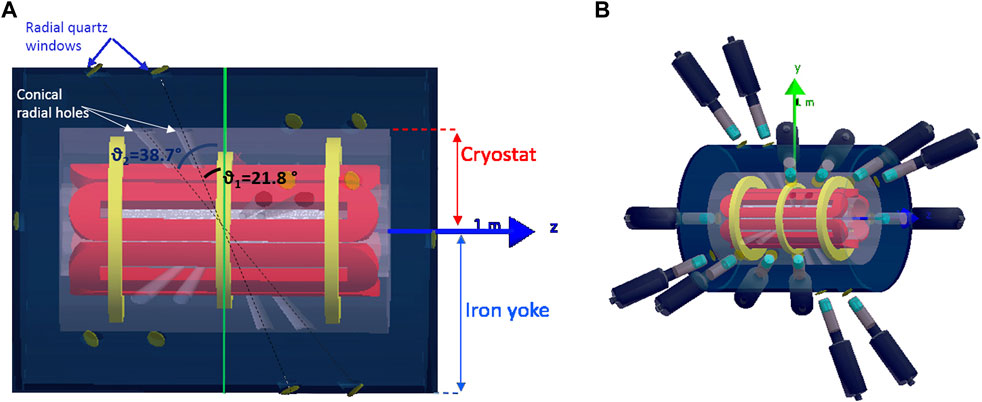
FIGURE 1. (A) Schematic drawing showing the three superconducting coils used for axial confinement (in yellow) and the hexapole used for radial confinement (in red). A single cryostat, depicted in light blue, contains all magnetic elements while the dark blue represents the region surrounded by the iron yoke. Radial quartz windows indicated in yellow are used in correspondence of the conical radial holes created in the chamber to allow for the measurement of the γ-rays emitted by the daughter nuclei following the β‐decay. (B) Schematic drawing of the magnetic trap with HPGe detectors placed around it. HPGe detectors are placed around the trap in correspondence of conical apertures in the cryostat.
No potential effects due to the presence of the magnetic field are expected on the charge collection efficiency (and therefore on the detector resolution) since the stray field will be of the order of 100 G.
2.1 The array geometry
The design of the γ array represents a compromise between the best detection efficiency achievable and the mechanical constraints imposed by the feasibility of creating a large number of apertures in the cryostat and the yoke without altering the magnetic field shape. Three conical apertures have been created in the interspace of each element of the hexapole in order to use it as a collimator and, at the same time, as a shield against the photon flux coming from the walls of the plasma chamber so to improve the signal-to-noise ratio. Such a choice allows for the placement, around the trap, of 12 HPGe detectors and six diagnostic tools (X-ray CCD pin-hole cameras, X-ray detectors, optical spectrometer, microwave polarimeter, RF probes and Thomson Scattering). As shown in Figure 2, two apertures are located at the same angle relative to the x axis while a third aperture is placed only on one side at a larger angles. This configuration rules out the regions of the magnetic trap where the B field lines are more intense and the electrons would be focalized by the magnetic field generating an intense background noise due to in plasma self-generated bremsstrahlung X-rays emission. All the aperture axis point to the center of the plasma chamber so that opposite apertures are collinear (see Figure 2). The same axis will be used to place the HPGe detector axis using a dedicated mechanical infrastructure.
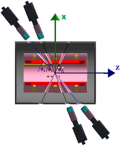
FIGURE 2. Cross-sectional drawing of the magnetic trap and the HPGe detectors. The lines of sight created in the cryostat and the yoke to have access to the plasma chamber and to be able to measure the in-plasma γ rays emitted after the β decay of the radioisotope are clearly visible.
GEANT4 simulations were performed to estimate the total detection efficiency of the setup and to evaluate the feasibility of the experiments. The total detection efficiency was evaluated assuming a cylindrical active part equal to one of GALILEO detectors (Gamma Array of Legnaro INFN Laboratories for nuclEar spectrOscopy [13]) which will be used during the first PANDORA experimental campaign thanks to a Collaboration Agreement, already signed, between the GAMMA and PANDORA collaborations. Gamma-rays of different energies were simulated changing the energy of the source in the range from 100 keV to 2 MeV. An isotropic ellipsoidal source placed in the center of the plasma chamber having the three semi-axes lengths equal to 79 mm, 79 mm and 56 mm (x, y, z) was used to simulate the γ-ray emission from the plasmoid, i.e., a plasma volume whose shape and size are defined by the employed confining magnetic field in the PANDORA plasma trap.
The results of the simulations are shown in Figure 3. The total photopeak detection efficiency reaches a maximum at Eγ =200 keV, then progressively decreases with increasing energy. Between 1400 keV and 2000 keV the efficiency is rather constant to a value of 8 × 10⁻⁴. Such a value, while being apparently small compared to the typical values of the photopeak efficiency of the arrays used nowadays, is however sufficient, due to the high number of decaying ions present in the plasmoid, to measure the predicted variations in the decay rates. This critical aspect was verified, through simulations, for the first physic cases selected in PANDORA (see Table 1) for their relevance in s-process nucleosynthesis: 176Lu, 134Cs, 94Nb [5]. All three nuclei are expected to undergo significant variations of their half-life in plasma environment.
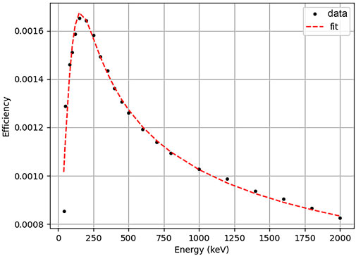
FIGURE 3. Total detection efficiency of the HPGe γ array as a function of the γ-ray energy. Dashed line shows the fit of the data with a Radware-like function.
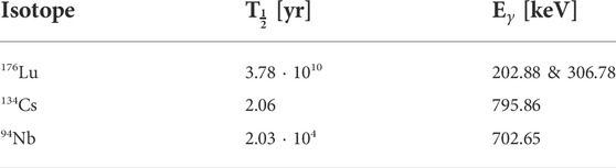
TABLE 1. The three physic cases to be investigated during the first PANDORA experimental campaign. For each isotope the value of the half-life
At the working conditions of PANDORA (kTe about 10 keV, where Te is the electron temperature) the 176Lu, a very long-lived nucleus in laboratory conditions with a T1/2 = 3.78 ⋅ 1010 yr, is expected to increase its decay rate up to about six order of magnitude while the neutral 94Nb, characterized by a T1/2 = 2.03 ⋅ 104 yr, is predicted to increase its decay rate in plasma (at kTe around 10 keV) of five orders of magnitude relative to the value measured in neutral atoms. The 134Cs has the shortest T1/2 among the three isotopes to be investigated, its value being equal to 2.06 years. In this last case the predicted increase of the decay rate due to in plasma ionization is one order of magnitude. Simulations of real experimental runs, assuming a plasma volume of 1500 cm3 and a concentration of the radioactive isotope ranging from 1011 ions/cm3 for 176Lu case to a much smaller value of about 106 ions/cm3 for 134Cs, show that to collect the statistics needed to achieve a 3σ-confidence level on the decay rate measurement, experimental runs should last from several days to about 3 months, depending on the isotope under investigation [5, 7]. Such a result clearly indicates that the sensitivity of the setup depends not only on the total detection efficiency of the HPGe array but also on the concentration of decaying ions confined in the trap (a value that can be tuned in each experiment considering also the possible limits imposed by radioprotection issues to the maximum total activity achievable) and on the expected variation of the half-life of the radioactive ion species.
Once the experimental approach will be well established, the PANDORA setup could allow a systematical investigation of several physic cases of β-decaying nuclei in plasma, related to nuclear-astrophysics processes and cosmology (BBN, s-processing nucleosynthesis, Cosmo-Chronometers, Early Solar System formation), with the restriction to those nuclei characterized by an emission of a γ-ray from the daughter nuclei populated in the β-decay process.
3 Front and back-end electronics
The standard readout chain of the HPGe from the GALILEO array [13] is based on custom-made electronics, from the pre-amplifier down to digitizers and pre-processing electronics. This electronic chain, developed in collaboration with the AGATA [14] collaboration, has been designed to accommodate a large number of channels, with a dedicated synchronization system. Due to the complexity of the system and the specificity of the PANDORA project whose experimental conditions in the magnetic trap lead to a high counting rate on HPGe array (up to 50 kHz on each detector) over a large period of time, the choice was made to simplify the readout electronics in order to improve its reliability and maintainability over long periods. For this reason it was decided to use commercially available modules for the readout.
3.1 Germanium detector pre-amplifiers
The PANDORA detector pre-amplifiers are based on the successful discrete-type model used to perform the readout of the GALILEO array. The circuit is divided into two parts: a cold one and a warm one. The cold part is constituted by the input JFET transistor, the feedback capacitor and feedback resistors. These are placed in close contact with the detector, inside the cryostat. The remaining part of the first pre-amplifier stage and the second stage are placed outside the cryostat and mounted on conventional FR4 boards. Given the non-conventional requirements in terms of linearity, noise and bandwidth, the operational amplifier that constitutes the warm part of the first stage is not a commercial one but instead is full-custom and made of discrete components.
The original device is powered with ±12 V and ±6 V, although these values have been changed to comply with the different requirements of PANDORA. In particular, the power rails have been modified as shown in Figure 4. A+24 V supply line has been added to extend the dynamic range of the integrator stage. This allows the pre-amplifier to handle a higher event rate that induces, due to the detector DC coupling, a natural random walk on the output node. This modification required the substitution of some bipolar transistors (MMBTH81) with similar models (MMBT3906) that are tolerant to higher voltages. This substitution was applied only on the integrator output stage and after careful considerations on the overall circuit bandwidth. The signal is then AC-coupled to the following Pole-Zero (PZ) stage, that reduces the signal decay constant down to 50 µs. At the same time the AC coupling suppresses the random walk and stabilizes the baseline.
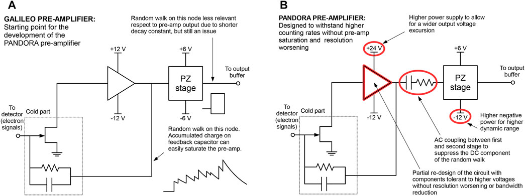
FIGURE 4. Simplified representation of the modifications of the PANDORA pre-amplifier [panel (B)] with respect to the GALILEO one [panel (A)].
Since the ADC dynamic range is narrower than the pre-amplifier one, high-energy signals can induce saturation in the digitizer. To avoid this, an innovative solution has been implemented. The PZ stage is based on a 4.7 nF capacitor and a resistive discharge network. When the signal crosses the chosen upper dynamic range limit, a current generator is activated that discharges the capacitor until the output voltage signal is brought back to 0 V in some microseconds. In this way the digitizer can correctly record the incoming signals without saturating and without waiting for the spontaneous decay of high-energy signals. Under-threshold events (dashed lines) with natural exponential decay are shown in Figure 5A) compared to fast-reset ones (solid lines). The latter have a triangular shape and fall back to the quiescent operating point in some microseconds.
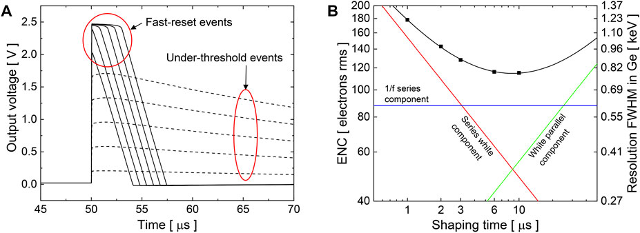
FIGURE 5. (A) Under-threshold events (dashed lines) compared to fast-reset events (solid lines). The signals with amplitude exceeding the ADC range are swiftly resetted thanks to a controlled current generator. (B) Pre-amplifier resolution in electrons r.m.s. and in keVGe FWHM. The calculated noise components are plotted against the experimental points. Equivalent noise charge data is reported in Table 2.
More advanced techniques are under study to implement the fast-reset solution directly at the first pre-amplifier stage. Both hybrid discrete-integrated [15] and fully-integrated pre-amplifiers [16, 17] that include the fast-reset circuit referred directly at the input node are under development.
An accurate selection of the input transistor, integrated in the cryostat, together with the minimization of the second-stage noise allows for a best resolution of 115 electrons rms, equivalent to 0.8 keV in Germanium. The trend of the detector resolution for different shaping times is plotted in Figure 5B) for the values reported in Table 2. The nominal signal leading-edge rise time (10%–90%) is 30 ns.
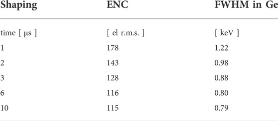
TABLE 2. Pre-amplifier resolution, measured with an analog quasi-gaussian shaping amplifier, expressed in electrons r.m.s. and keV FWHM in Germanium detector for different shaping times.
3.2 Readout electronics
First implementation of the readout electronics is based on the V1725S module from CAEN. Those 16-channels boards are equipped with Flash ADC with a 14-bit resolution and a 250 MHz sampling rate. Input signal of the CAEN digitizer are single-ended; since the pre-amplificator output of the GALILEO detectors are differential, dedicated conversion modules need to be developed. To test the readout, a Mesytec MDU-8 Differential-to-single-ended was used.
Since HPGe signals are long (rise time ∼ 100–300 ns, decay ∼ 45 μs), the amplitude of the signal, proportional to the incident energy of the photon, is extracted using a moving window de-convolution algorithm based on the Jordanov trapezoidal filter [18]. Standard parameters used at low rate (≤15 kHz) are based on an integration time around 6 μs. This long integration allows one to obtain energy resolution of 2–2.3 keV at 1332 keV using the coaxial detectors of GALILEO.
In the PANDORA configuration, our gamma detection system will work under harsh conditions due to the self-emitted background produced by electron Bremsstrahlung. Such a production mechanism will lead to a rather steep exponentially decreasing spectrum giving rise to a counting rate of about 50 kHz background in each detector. An evaluation of the behavior of the energy resolution of our detector/electronics system as a function of different low energy (50–300 keV energy range) counting rates is shown in Figure 6. For this test we have prepared a multi-source measurement system composed by a 150 kBq 60Co source placed at 10 cm from the detector, generating a fixed counting rate of 1.5 kHz, and a stack of sources, composed of 241Am, 133Ba and 137Cs placed on a movable vertical plate, in order to simulate different low energy background counting rates. In Figure 6, we reported the FWHM measured on the 1332 keV transition as a function of the total counting rate. All the measurements were taken over 10 min runs. It is worth pointing out that all the measurements were performed using the same configuration of the trapezoidal filter. Even so, at the rate expected for the PANDORA configuration, the resolution of the detector remains around 3 keV. For a better comparison, the obtained spectra at five different rates are reported in Figure 7, no large asymetry of the peak is observable. Due to the multi-source measurement and the activity of the Cs source, the pile-up of two 661-keV transition is visible at ∼ 13320 ADC channel. It is worth pointing out that even at 100 kHz the peak from the 60Co source (1332 keV) and resulting sum-peak of the 137Cs source (1322-keV) are still well separated.
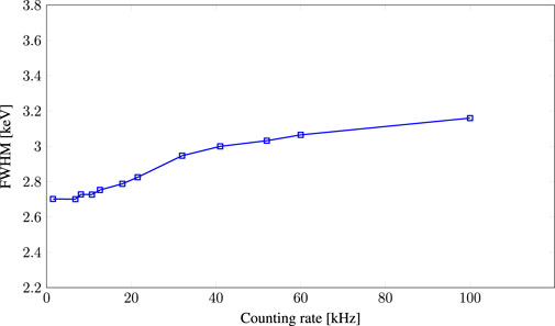
FIGURE 6. Measured FWHM of a GALILEO HPGe single crystal as a function of the counting rate using the V1725 CAEN digitizer. The HPGE detector was equipped with the new pre-amplifier. A 150 kBq 60Co sources was placed at 10 cm from the detector, generating a fixed counting rate of 1.5 kHz. A stack of sources, composed of 241Am, 133Ba and 137Cs, was placed on a movable vertical plate in order to simulate different low energy background counting rates. All the measurements were taken over 10 min runs.
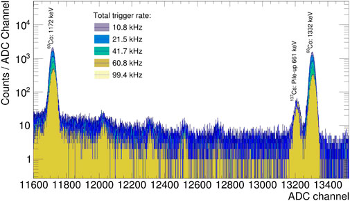
FIGURE 7. Stacked spectra obtained for five different total counting rates. The peak lying close to the 1332-keV line (13220 ADC channels) is due to the pile-up peak of the intense 137Cs source.
A second test was performed to check the stability of the system at large counting rate (50 kHz). Energy versus time matrix is shown in Figure 8 to illustrate the stability of the newly developed pre-amplifier and readout electronics. No significant deviation is observed over the 10 h run.
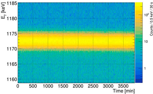
FIGURE 8. Energy vs. Time measured of 60 h using the multi-source with a total rate of 50 kHz. The energy axis has been zoomed on the 1172-keV transition coming from the 60Co source.
4 Data acquisition system
The proposed data acquisition system is based on the XDAQ framework. XDAQ has been developed and is maintained by CERN [19] and allows the end-users to focus on the development of specific applications tuned for their setup while taking advantage of all the tools present in the framework (peer-to-peer communication, application control and monitoring, etc.). All current developments are based on the XDAQ v15 and running under CentOS 7 with gcc 8.
4.1 Readout unit
The Readout Unit (RU) is the only application directly communicating with the back-end electronics. For simplicity, the RU is largely based on the CAENDigitizer library 1. The role of the RU can be described as follows: it takes the raw buffers from the electronic board and moves them to the XDAQ data stream to be sent to the next application of the distributed acquisition system.
4.2 Filter units
The high counting rate sustained by the electronics and the RU is mostly due to the background radiations originated by the electron bremsstrahlung in the plasma trap that will account for an average rate of 50 kHz per detectors. It is worth pointing out that state-of-the-art γ-ray arrays as AGATA and GRETA, although designed to withstand rates of 80–100 kHz, are generally not operating in trigger-less mode. In the case of AGATA, a trigger processor device allows to perform an hardware selection of the events based on fold conditions in AGATA and/or eventual coincidence with complementary detectors. While the detectors are able to trigger at more than 80 kHz, in the present configuration, the AGATA DAQ and in particular the pulse shape analysis (PSA) used to determine the γ-ray interaction position in the HPGe crystal can only be fully operated up to rates of about 4 kHz per crystal using the grid-search algorithm keeping the dead-time below 10%. In the case of PANDORA, reducing the data frame size to the minimum possible at 50 kHz per crystal, the resulting data bandwidth on disk would be around 1 TB per day. Since data taking will span over several weeks, a data reduction needs to be applied before writing data on disk.
For this reason, filter units have been implemented in the data chain. For example, the first filter unit is used to monitor the data stream and to extract information about the rates (trigger, pile-up, saturation, lost events) to be sent to the monitoring system. At this level, a first reduction of the data stream could be applied by using simple energy windows on the individual channels. The second filter unit, placed after a time sorter and event builder, could be used for a further reduction based on event fold. The system is modular and additional units could be added in function of the requirement of each experiment.
4.3 Data quality monitoring
Data quality monitoring can be performed in different ways:
• Implementing spectra directly in the DAQ applications;
• Adding a parallel output to the DAQ application, consisting in a TCP-server to spy the data.
The first solution offers the possibility to have a precise idea of the total statistics available in a certain amount of time. Thanks to recent developments, it is now possible to reset those spectra. However, since they are directly implemented within the DAQ applications, they are generally less flexible and cannot be modified easily (i.e., binning, range, conditions).
The second solution, is to spy the data flux to monitor the data quality. Depending on the experimental conditions, in particular the data bandwidth, only a fraction of the data can be monitored. Nevertheless, this solution offers the possibility to monitor the data at different level of the DAQ in a relatively easy way. Although it requires the development of small analysis codes, it is worth noting that the developed code could be used also for the offline analysis since both spy and data on disk have a common format.
4.4 Run control and system monitoring
XDAQ distributed acquisition is described in an XML-file containing all the applications and the relation between them. Each application corresponds to a process running on a specific computer. To simplify the organization and the control of the data acquisition, the choice was made to run all the applications within a terminal multiplexer using TMUX open-source solution. Management of the TMUX session is directly performed by the run control following the DAQ topology. Separated windows are automatically generated for each DAQ level and divided into panes in case more than one application per level is required.
A dedicated modular run control based on Python3 has been developed for the GALILEO array and further improved for the installation of the AGATA at the LNL. The present solution includes a constant monitoring and alert system of the run experimental conditions. Open-source time series solution, such as Graphite or InfluxDB, are used to keep track of the detector conditions (temperature, bias voltage and current), the electronic status (board temperature, triggering rate) and the DAQ system (load of the acquisition and disk server, data bandwidth). The system will be used for the HPGe data acquisition, its flexibility makes the inclusion of the information related to the plasma conditions relatively straightforward.
5 Detector support system
The detector support system (DSS) is a critical part of the project. It includes several hardware components (detector preamplifier and digitizer LV power supply, automatic HPGe cooling system, … ) as well as an integrated slow-control software to manage and supervise the detector operations (HPGe HV and temperature, preamplifier and digitizer LV, UPS status, … ). All these components are necessary to guarantee the normal operation of the 14 GALILEO detectors placed around the plasma trap.
The power consumption of the electronics (preamplifiers, HV system and HV shutdown board) is relatively small: about 20 W per channel, i.e. the total power requirements of a small array with 14 HPGe detectors is about 2 kW, including the internal dissipation of power supply modules and the LN2 cooling infrastructure.
5.1 Autofill system
Each HPGe detector cryostat is equipped with one Pt100 resistor, placed along the cold finger, close to the dewar, to monitor the detector behaviour and to guarantee a fast reaction of the cooling system if LN2 is missing. The measured resistance is also compared to a reference value to inhibit the HV bias if a temperature above the normal range of working conditions is detected.
A LN2 distribution system is needed to cool the HPGe detectors. The cryogenic system is based on a pressurized container, positioned in the proximity of the HPGe detectors and connected to distribution manifolds. Flexible hoses will connect the valve controlled ports in the manifold to individual detectors. Automatic/manual procedures are implemented to refill each detector Dewar with LN2 at regular intervals (usually every 12 h) or to keep the detector at the working temperature (forced fill). To define the volume of the LN2 container the total volume of the installation area and the minimum acceptable O2 concentration for breathing will be considered. Oxygen level sensors will be installed in the area to monitor the saturation levels.
From the long-standing experience with GALILEO detectors, an array of 14 GALILEO detectors will have an estimated LN2 consumption of 100 L/day.
The control program of the filling system resides entirely on a cRio hardware without using external computing resources. In addition to monitor the status of the detectors and a restricted set of actions, accessible to the occasional user through a dedicated Graphical User Interface, an expert operator is able to access (read and modify) the parameters that control the behavior of the system.
The infrastructure (LN2 transport line, distribution manifolds, valves, sensors, … ), the cRio hardware platform and the control program of the filling system use the same components already adopted in the system installed on the GALILEO spectrometer at LNL. The only modifications (internal/external pressurized container, metal pipes connecting the detectors, … ) are determined by the characteristics of the location where the new system will be installed.
5.2 LV and HV power supply
Due to the modification made on the pre-amplifiers to sustain the high-counting rate, new Low Voltage Power Supply will have to provide +24V, -12 V and ± 6 V. Considering the limited number of high voltage channels required for the setup, several technical solutions are still under evaluation. All of them are consistent with the possibility to implement a bias shutdown using an external signal, e.g. the signal generated from the autofill system combined with the shutdown signal from the detector.
5.3 High purity germanium detectors infrastructure
The experimental runs foreseen for PANDORA will have a duration which could extend up to a few months. Detector performances can deteriorate with time especially considering the harsh conditions to which they will be exposed. Therefore, in order to be able to repair, test and run ordinary maintenance procedures on the HPGE detectors it was decided to build, at the LNS, a detector laboratory to cope with these needs. Due to the long-standing experience acquired by the researchers and technicians of the INFN—Laboratori Nazionali di Legnaro on the use and maintenance of HPGe detectors a period of training of the LNS personnel is foreseen as well as a remote support for the more complex repair works that will be coordinated with the GAMMA collaboration and the LNL DetLab [20]. This HPGe detectors facility would be the first laboratory of this type in Sicily and could become an excellent support for other activities which could make use of HPGe detectors in the LNS, the Universities or other institutions and companies in the Region.
6 Summary
The detection of the γ-rays emitted by daughter nuclei of highly ionized β-decaying isotopes trapped in the confined plasma, allows for the estimation of β-decay rates as a function of the plasma main parameters (density and temperature). From the point of view of the gamma detection, we have to deal with the trap geometrical constraints which limit the number and the solid angle covered by the γ-ray detectors and with the plasma self-emitted background radiation that produces a huge total counting rate.
The HPGe detector array for the PANDORA plasma trap has been designed with particular emphasis on maintaining the best resolution of the HPGe detectors during long periods of time since it affects the signal-to-noise ratio as well as the optimal data processing at the mentioned high counting rates. The HPGe pre-amplifiers, digitizers and pre-processing electronics chain developed at AGATA and GALILEO, have been adapted to PANDORA HPGe detectors by simplifying the readout and improving the reliability and maintainability over long periods. Tests of the energy resolution of the system as a function of the total counting rate indicate that the system is able to handle high counting rates (about 50 kHz) without any significant worsening of the detectors energy resolution which clearly remains the main parameter to be kept under control when dealing with high background counting rates. For this reason the project of the new array for PANDORA includes an efficient and safe detector support system which will assure stable conditions for the HPGe detectors for long time periods and a detector lab that could guarantee the maximum number of detectors working with the best achievable performances.
Data availability statement
The raw data supporting the conclusions of this article will be made available by the authors, without undue reservation.
Author contributions
DS and EN contributed to the design study of the array. EN did detailed simulation of the array geometry DS wrote the paragraphs 1 and 2 of the paper AG wrote paragraph three and four of paper and made tests on the electronics RM wrote the paragraph concerning the LN2 filling system (part of paragraph 5) SC and AP worked on design and realization of the modified pre-amp used in tests WR and DR wrote section 5.3 of the paper and worked on the HPGE detectors (test preparations) NT developed part of the DAQ LZ worked of the DAQ DN contributed to paper writing and coordinated the synergic activities between LNS and LNL. All authors contributed to manuscript revision, read, and approved the submitted version.
Conflict of interest
The authors declare that the research was conducted in the absence of any commercial or financial relationships that could be construed as a potential conflict of interest.
Publisher’s note
All claims expressed in this article are solely those of the authors and do not necessarily represent those of their affiliated organizations, or those of the publisher, the editors and the reviewers. Any product that may be evaluated in this article, or claim that may be made by its manufacturer, is not guaranteed or endorsed by the publisher.
References
1. Bahcall J. Theory of bound-state beta decay. Phys Rev (1961) 124:495–9. doi:10.1103/PhysRev.124.495
2. Jung M, Bosch F, Beckert K, Eickhoff H, Folger H, Franzke B, et al. First observation of bound-state beta − decay. Phys Rev Lett (1992) 69:2164–7. doi:10.1103/PhysRevLett.69.2164
3. Bosch F, Faestermann T, Friese J, Heine F, Kienle P, Wefers E, et al. Observation of bound-state β− decay of fully ionized 187Re: 187Re-187Os cosmochronometry. Phys Rev Lett (1996) 77:5190–3. doi:10.1103/PhysRevLett.77.5190
4. Naselli E, Mascali D, Biri S, Caliri C, Castro G, Celona L, et al. Multidiagnostics setups for magnetoplasmas devoted to astrophysics and nuclear astrophysics research in compact traps. J Instrum (2019) 14:10008. doi:10.1088/1748-0221/14/10/C10008
5. Mascali D, Naselli E, Torrisi G. Microwave techniques for electron cyclotron resonance plasma diagnostics. Rev Scientific Instr (2022) 93:033302. doi:10.1063/5.0075496
6. Leach KG, Grossheim A, Lennarz A, Brunner T, Crespo López-Urrutia JR, Gallant AT., et al. The TITAN in-trap decay spectroscopy facility at TRIUMF. Nucl Instr Methods Phys Res Section A (2015) 780:91–99. doi:10.1016/j.nima.2014.12.118
7. Naselli E, Ràcz R, Biri S, Mazzaglia M, Celona L, Gammino S, et al. Innovative analytical method for x-ray imaging and space-resolved spectroscopy of ECR plasmas. Condens Matter (2022) 7:5. doi:10.3390/condmat7010005
8. Mascali D, Santonocito D, Amaducci S, Andó L, Antonuccio V, Biri S, et al. A novel approach to β-decay: PANDORA, a new experimental setup for future in-plasma measurements. Universe (2022) 8:80. doi:10.3390/universe8020080
9. Naselli E, Santonocito D, Amaducci S, Galatá A, Goasduff A, Mauro G, et al. Design study of a HPGe detectors array for β-decays investigation in laboratory ECR plasmas. Front Phys (2022) 10:935728. doi:10.3389/fphy.2022.935728
10. Torrisi G, Naselli E, Mascali D, Donato LD, Sorbello G. mm-wave interferometer-polarimeter and profilometry design study for retrieving plasma density in the pandora experiment. Front Astron Space Sci (2022) 9:949920. doi:10.3389/fspas.2022.949920
11. Mazzaglia M, Biri S, Emma G, Finocchiaro G, Galatà A, Mauro G, et al. A system for plasma parameters evaluation in compact magnetic traps aiming at in plasma β-decay investigation. Frontiers (2022). submitted in this special issue.
12. Mauro G, Celona L, Torrisi G, Pidatella A, Naselli E, Russo F, et al. An innovative superconducting magnetic trap for probing β-decay in plasmas. Front Phys (2022) 10:931953. doi:10.3389/fphy.2022.931953
13. Goasduff A, Mengoni D, Recchia F, Valiente-Dobón J, Menegazzo R, Benzoni G, et al. The galileo γ-ray array at the legnaro national laboratories. Nucl Instr Methods Phys Res Section A: Acc Spectrometers, Detectors Associated Equipment (2021) 1015. 165753, doi:10.1016/j.nima.2021.165753
14. Akkoyun S, Algora A, Alikhani B, Ameil F, de Angelis G, Arnold L, et al. Agata—Advanced gamma tracking array. Nucl Instr Methods Phys Res Section A: Acc Spectrometers, Detectors Associated Equipment (2012) 668:26–58. doi:10.1016/j.nima.2011.11.081
15. Pullia A, Zocca F, Capra S. Note: A 102 dB dynamic-range charge-sampling readout for ionizing particle/radiation detectors based on an application-specific integrated circuit (asic). Rev Scientific Instr (2018) 89:026107. doi:10.1063/1.5012081
16. Capra S, Mengoni D, Duenas J, John P, Gadea A, Aliaga R, et al. Performance of the new integrated front-end electronics of the TRACE array commissioned with an early silicon detector prototype. Nucl Instr Methods Phys Res Section A: Acc Spectrometers, Detectors Associated Equipment (2019) 935:178–84. doi:10.1016/j.nima.2019.05.039
17. Capra S, Pullia A. Design and experimental validation of an integrated multichannel charge amplifier for solid-state detectors with innovative spectroscopic range booster. IEEE Trans Nucl Sci (2020) 67:1877–84. doi:10.1109/TNS.2020.3006892
18. Jordanov VT, Knoll GF, Huber AC, Pantazis JA. Digital techniques for real-time pulse shaping in radiation measurements. Nucl Instr Methods Phys Res Section A: Acc Spectrometers, Detectors Associated Equipment (1994) 353:261–4. doi:10.1016/0168-9002(94)91652-7
19. Gutleber J, Murray S, Orsini L. Towards a homogeneous architecture for high-energy physics data acquisition systems. Comp Phys Commun (2003) 153:155–63. doi:10.1016/S0010-4655(03)00161-9
20. Sajo-Bojus Se. a., Rosso D, Sajo Castelli A, Napoli D, Fioretto E, Menegazzo R, et al. Hpge detectors long time behaviour in high-resolution gamma spectrometry. Nucl Instr Methods Phys Res Section A: Acc Spectrometers Detectors Associated Equipment (2011) 648:132–8. doi:10.1016/j.nima.2011.03.031
Keywords: γ-ray spectroscopy, HPGe detectors, front-end electronics, digital electronics, distributed DAQ, plasma trap
Citation: Goasduff A, Santonocito D, Menegazzo R, Capra S, Pullia A, Raniero W, Rosso D, Toniolo N, Zago L, Naselli E and Napoli DR (2022) A high resolution γ-ray array for the pandora plasma trap. Front. Phys. 10:936081. doi: 10.3389/fphy.2022.936081
Received: 04 May 2022; Accepted: 06 September 2022;
Published: 07 October 2022.
Edited by:
Marialuisa Aliotta, University of Edinburgh, United KingdomReviewed by:
György Gyürky, Institute of Nuclear Research (ATOMKI), HungaryJack Henderson, University of Surrey, United Kingdom
Copyright © 2022 Goasduff, Santonocito, Menegazzo, Capra, Pullia, Raniero, Rosso, Toniolo, Zago, Naselli and Napoli. This is an open-access article distributed under the terms of the Creative Commons Attribution License (CC BY). The use, distribution or reproduction in other forums is permitted, provided the original author(s) and the copyright owner(s) are credited and that the original publication in this journal is cited, in accordance with accepted academic practice. No use, distribution or reproduction is permitted which does not comply with these terms.
*Correspondence: D. Santonocito, domenico.santonocito@lns.infn.it