High-sensitivity multi-channel DPSK system with real-time phase lock controller for free-space optical communication
 Duorui Gao1,2†
  Tianlun Li3†
  Zhuang Xie1,2 Jiacheng Meng1 Shuaiwei Jia1,2 Zhaofeng Bai1
  Wei Wang1* Xiaoping Xie1,2*
- 1State Key Laboratory of Transient Optics and Photonics, Xi’an Institute of Optics and Precision Mechanics, Chinese Academy of Sciences, Xi’an, China
- 2University of Chinese Academy of Sciences, Beijing, China
- 3Key Laboratory of Physical Electronics and Devices of Ministry of Education, School of Electronic Science and Engineering, Xi’an Jiaotong University, Xi’an, China
To overcome the power jitters in satellite-to-ground communications caused by atmospheric turbulence, a type of DPSK free-space communication system, assisted by a self-designed real-time phase lock controller, has been established. The system can effectively compensate for power swings in communication links and hence achieve high sensitivity. The wavelength division multiplexing technique is applied to a four-channel DPSK system to provide greater link capacity. With the data rate of a single channel as 2.5 Gbps and unencoded BER as 1 × 10⁻³, reception sensitivity has been obtained at −53.58 dBm (13.69 photons/bit), −53.59 dBm (13.66 photons/bit), −53.61 dBm (13.59 photons/bit), and −53.63 dBm (13.53 photons/bit) for each independent channel, respectively. The gap between our sensitivity result and the theoretical limit has narrowed to about −3.5 dB. Simultaneously, the DPSK receiver, with our self-designed phase lock controller, has stabilized reception of optical power fluctuations that range from 0 to 40 dB. Additionally, the impact of a four-wave mixing effect on multi-channel system performance has been investigated in detail. Our experimental results present a novel solution for the superior performance of free-space communication links.
Introduction
Because of its high-bandwidth, high-speed, and high-security features [1–5], free-space optical communication (FSOC) offers a feasible and valid solution for bottlenecks in microwave communication and for realizing massive real-time transmission of data. Concurrently, and because of the inherent benefits of its small size, lightweight, and low power consumption—capable of keeping up with the communication demands of booming space activities—the FSOC terminal can be considered an ideal satellite payload [6, 7]. Thus far, the data rate of satellite laser communication links has been found to approach Gbps magnitude [8, 9]. However, through wavelength division multiplexing (WDM) technology, this rate is predicted to reach magnitudes of dozens, even hundreds, of Gbps [10, 11].
Under the diverse modulation method, the proven techniques of FSOC are mainly divided into two main categories: non-coherent and coherent communication systems. Intensity modulation and direct detection (IM-DD) are utilized in non-coherent systems, which have the advantages of simplicity of structure and high reliability (although with undesirable levels of reception sensitivity) [12]. By contrast, coherent communication systems, which combine phase modulation with coherent detection, deploy the coherent superposition of local-oscillator (LO) and signal optical fields, supporting high sensitivity, high modulation rates, and strong anti-interference capability [13, 14]. Coherent communication modes mainly consist of binary phase shift keying (BPSK) and differential phase shift keying (DPSK). Since the DPSK format has less strict requirements for laser source linewidth, many commercial or strategic demonstrations have a preference for such systems, including the Laser Communications Relay Demonstration (LCRD), Integrated LCRD Low-Earth Orbit User Modem and Amplifier Terminal (ILLUMA-T), and the Japanese Data Relay System (JDRS) [15–17]. Due to the turbulence of the atmosphere, satellite-to-ground laser communication links suffer from random optical power fluctuations of the order of milliseconds (ms), which lead to inferior demodulation of the DPSK signal and an increase in the system bit-error rate (BER). To weaken the negative impact of these random fluctuations, several methods have been explored to reduce the penalty associated with other photoelectric devices [18]. Clearly, the optimal solution is to fundamentally smooth out or level of this kind of power jitter.
To this end, a real-time phase lock controller, based on a large-scale power jitter compensation method, has been designed to effectively compensate for optical power swings ranging from 0 to 40 dB. Applying this controller and the WDM technique, the resulting four-channel DPSK communication system has competitive receiving sensitivity that approaches the theoretical limit. Meanwhile, the impact of the four-wave mixing effect of high transmitted optical power on multi-channel system performance is elaborated in detail. The phase-lock controller can be considered an alternative solution for the power fluctuation problem in FSO communication links. At the same time, the WDM technique can be effectively combined with our self-designed phase-lock controller, which means the controller has potential in the application of multiplexed high-speed laser communication systems. Our demonstration indicates that adding a phase lock controller to the DPSK system leads to an improvement in receiving sensitivity, which in turn lays a vital foundation for optimizing the performance of the receiving terminal while mitigating the effects of optical power jitter.
Principle and experiments
Principle large-scale power jitter compensation
In the high-speed DPSK transceiver system, a pseudo-random bit sequence (PRBS) from a pattern generator is differentially pre-encoded and then transferred to a Mach–Zehnder modulator (MZM) to generate the DPSK optical signal. The transmission function can be presented as follows: [19]
where Eout(t) and Ein(t) = eiωct represent output and input optical fields, respectively; ωc = 2πf0 is the angular frequency of the optical carrier, with f0 being the frequency; Vπ is the half-wave voltage of MZM; and Vin(t) and Vbias are the driving and bias voltage of MZM, respectively. When Vbias = Vπ, Vin(t) = V (t)·a(t), with a(t) = ±1 [a(t) represents the 1 or 0 bit in the pre-coded PRBS], the DPSK optical signal can be generated with the transmission function as follows: [20]
After modulation, the optical signal was transferred to a high-power Er3+-doped fiber amplifier (EDFA) before being routed to optical antenna for further transmission over the free-space channel. Subsequently, the DPSK signal can be captured by the receiving terminal and defined mathematically by the following transmission function:
where ERX(t) represents the optical field of the received signal and A(t) is the random fluctuation function of optical power.
After a certain free-space distance of transmission, the optical signal is detected by the collimator at the receiving terminal. As illustrated in Figure 1A, an optical coupler (OC1) is introduced before the normal demodulation process. One of the signal branches enters the delay line interferometer (DLI) (path 1, Figure 1A), and the other branch is transformed into the electrical signal via a photodetector (PD), before being imported into the phase-lock control system (path 2, Figure 1A). The path 1 optical signal is converted into a detectable electrical signal by a balanced photo-detector (BPD) and is processed by the integrated transimpedance amplifier (TIA). Next, one channel of the output electrical signal is inputted into the envelope detection unit for peak-to-peak detection and is then transferred into the phase lock controller. Subsequently, two independent electrical signals from path 1 and path 2 undergo time synchronization, power jitter removal, as well as correlation detection with a scrambler signal, in order to calculate and update the bias voltage of DLI in real time. The optimized bias voltage guarantees the working position of DLI, and thus ensures the superior DPSK receiving performance.
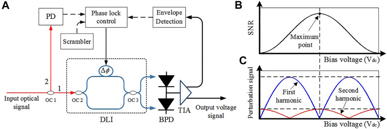
FIGURE 1. (A) The block diagram of the high-speed DPSK receiver system. (B,C) The relationship between SNR and the harmonic component of the perturbation signal with corresponding bias voltage.
The output optical field after OC 2 can be resolved by the following matrix:
where T is the reciprocal of the system rate and Δϕ is the absolute phase-delay. Since the variation frequency of spatial optical power swings is much less than the signal rate, the approximate condition A(t)≈A(t-T) can be adopted to simplify the calculation. Meanwhile, the transfer matrix M of the OC 3 can be expressed as
where ρ is the splitting ratio of OC 3 (Figure 1A). Therefore, the matrix of the optical field at the output port of OC 3 can be conducted as
The optical signal expressed in Eq. 6 will be detected by a BPD and conditioned by a TIA. Assuming ρ = 0.5, the output current from BPD (I1 and I2) is supposed to be defined by the corresponding input optical field of BPD (E3 and E4) as follows:
It can be clearly seen that the value of the output current from BPD is proportional to the input optical power. By means of a differential operation, the output voltage Vsig of BPD can be calculated by [21]
where R is the transimpedance. Simultaneously, the average output optical power of the other phase-lock branch (
where r is the splitting ratio and P1 and P2 are the optical power for paths 1 and 2, respectively. Based on Eq. 9,
where
According to the actual operation of correlation detection, determining the value and the direction of the compensation is a matter of great necessity. To solve this problem, it is considered preferable to introduce to the DLI a perturbation signal with quite a low frequency. Getting through the BPD and envelope detection, the extracted perturbation signal carries out the correlation detection with the initial perturbation signal at the phase lock controller (Figure 1A).
Generally, the phase difference of DLI Δϕ can be expressed as [22]
where Vdc is the direct current (DC) bias voltage applied on the DLI; VDLI, as the constant, is the required voltage for the DLI to realize phase changing by π. The frequency of perturbation signal Vdither = v0cos(ω0t) is 1 kHz and has no impact on the original signal. When φ = ωcT + πVdc/VDLI and k′ = 2rk are fixed, the updated scale factor k′ of the feedback loop in the phase lock controller can be easily conducted as
Expanding Eq. 12 by the Taylor series and keeping three terms, k' can be illustrated as
And by further conducting, it can be expressed as follows:
Based on Eq. 14, the maximum value of scale factor k' can be approached by monitoring the value of the harmonic component of the perturbation signal. For instance, the first harmonic component is k1′ = (v0 − v03/8)cos(ω0t)sin φ, and the second harmonic component is k2′ = −v02cos(2ω0t)cos φ/4. Figures 1B,C illustrate the performance of the scale factor k' and the harmonic components of the perturbation signal under the same working bias voltage. When φ = ωcT+πVdc/VDLI = nπ, n = ±1, ±2, ±3, …, the first and second harmonic components correspond to the minimum and the maximum values, respectively. Thus, a superior signal-to-noise ratio (SNR) has been obtained. With our self-designed phase lock system, it is convenient to maintain the highest SNR of the output signal by continuously calculating and updating working voltages in real time, and apparently realizing the optimal coherent reception of the DPSK optical signal.
2.2 Experiment setup
In view of the correlation detection compensation method, the four-channel DPSK coherent communication system in this effort is presented in Figure 2. Four distributed-feedback (DFB) continuous-wave (CW) lasers (RIO, RIO0075-3-ITU-1) generated four corresponding WDM pulse signals with 100 GHz channel spacing, 10 kHz linewidth, and the central wavelengths of λ1 = 1,550.52 nm, λ2 = 1,551.32 nm, λ3 = 1,552.12 nm, and λ4 = 1,552.93 nm, respectively. Each signal was independently modulated by a MZM (iXblue, MXAN-LN-10, Vπ = 5.5 V), loaded with non-return-to-zero (NRZ) PRBS of length 27–1 from separate data sources. The inset of Figure 2 displays the spectrum of the four laser sources. The multiplexed signal is subsequently amplified by a high-power EDFA (KEOPSYS, CEFA-C-PB-HP) to prepare for coupling with the FSOC terminal, aimed at long-haul transmission over the free-space channel. In this effort, an electrical-control variable optical attenuator (VOA) is utilized to simulate the power jitter caused by atmospheric turbulence, and the spatial optical transmission distance is 1 m.
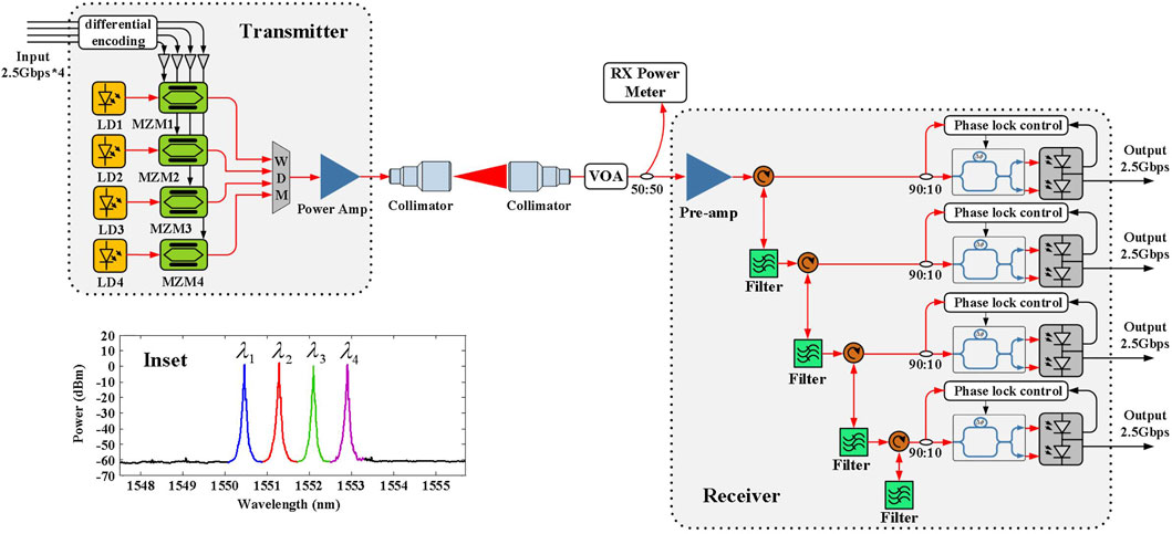
FIGURE 2. The architecture of the four-channel DPSK coherent communication system. Inset: the spectrum of the four-channel multiplexed signal.
The faded optical signal—resulting from the power jitter caused by atmospheric turbulence—is supposed to be captured via the optical antenna of the receiving terminal and coupled to the follow-up fiber. The received optical signal is split into two separate branches via a 50:50 splitter. One of the optical paths is applied to monitor the light power in real time, while the other is pre-amplified and routed into four cascaded fiber-Bragg gratings (FBGs) to faultlessly denoise with the purpose of extracting four separate channels of the optical signal. Each filtered optical signal is imported into the corresponding DLI to proceed with the self-differential demodulation of our self-designed phase-lock controller, which compensates for the demodulation-efficiency drops from optical power swings. Ultimately, each individual signal is converted into a baseband electrical signal by its corresponding BPD (Discovery Semiconductors DSC-R422) for further measurement and analysis.
Results and discussion
Receiving sensitivity
Receiving sensitivity is an essential indicator when assessing the performance of the free-space optical receiver. Figure 3A depicts the correlation between the communication BER and the received optical power for each single channel loaded with 2.5 Gbps PRBS. As the unencoded BER is 1 × 10⁻³, which allows forward-error correction codes to further reduce the BER to the range of 10–9, the receiving sensitivity of the four independent channels is measured as −53.58 dBm (13.69 photons/bit, 1,550.52 nm), −53.59 dBm (13.66 photons/bit, 1,551.32 nm), −53.61 dBm (13.59 photons/bit, 1,552.12 nm), and −53.63 dBm (13.53 photons/bit, 1,552.93 nm), respectively. It is impressive that there is only about −3.5 dBm loss compared with the theoretical limit, as −57.01 dBm (BER = exp(−ηNp/2)/2, η is also set to 1, so that the sensitivity corresponds to an ideal photodetector; Np is the number of photons) [23]. In our FSOC system, the penalty is mainly introduced by an optical pre-amplifier with a 4.5 dB noise coefficient, which is 1.5 dB larger than the theoretical limit of 3 dB. Additionally, about 1.5 dB loss caused by the out-of-band noise of the optical filter, and 0.5 dB loss from the phase lock controller are also taken into account. The eye diagrams for the four recovered channels of electrical signal are displayed in Figures 3B–E. Table 1 lists the reported BER performance of different DPSK communication systems. Compared with these results, the results of our experiment are objectively competitive.
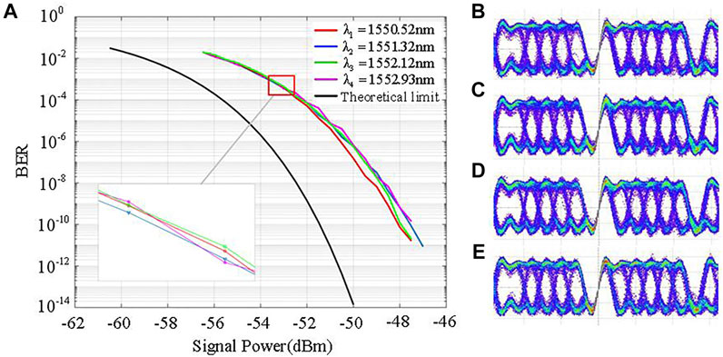
FIGURE 3. (A) BER for four channels of 2.5 Gbps DPSK signal. (B–E) Eye diagrams of four independent channels after demodulation.
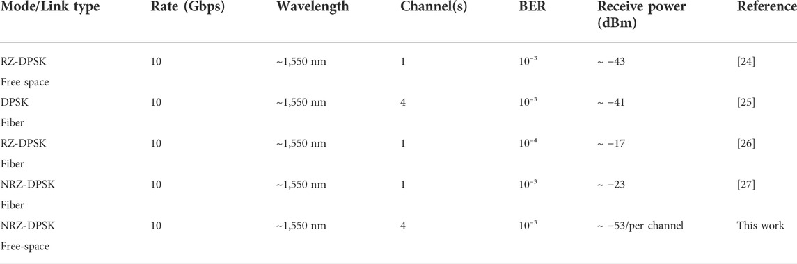
TABLE 1. Reported BER results for different DPSK links.
Optical power jitter
An electrical-control VOA was applied to simulate the optical power jitter with a frequency of 100 Hz and its scale ranging from 0 to 40 dB. The applied voltage of the self-designed phase lock controller is illustrated in Figure 4A. Point ① denotes an initial voltage applied on DLI when the phase lock unit is switched on and implies a lower demodulated SNR (Figure 4B). After that, the phase lock controller commences calculating the scale factor k′ of the initial voltage within part ②, keeping the scale factor at a maximum value by means of real-time voltage adjustment with progressive SNR (Figure 4C). Part ③ signifies that the scale factor k′ is real-time locked at a maximum value (with the maximum SNR) by the phase lock system (Figure 4D).
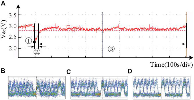
FIGURE 4. (A)Applied voltage on DLI for controlling the scale factor k′. (B–D) Eye diagrams for corresponding working point ①, part ②, and part ③.
On the strength of the above experiment and analysis, the optical power swings can be effectively compensated for using our self-designed phase lock system, which can productively optimize the coherent demodulation procedure.
Analysis of the FWM effect and transmitted optical power
Although high optical power is required for free-space long-haul transmission, the nonlinear optical (NLO) effects within the fiber receive a further boost from the increase in the optical power of the WDM system, especially the four-wave mixing (FWM) effect that occurs in the amplifying procedure within the transmitter. The optical amplification process has been utilized to investigate the probable influence brought about by FWM. Figure 5A exhibits the spectrum of four amplified laser sources, with the amplified power as 1, 2, 3, and 4 W, respectively. It is determined that the FWM effect occurs through optical amplification and generates multiple idle signals. With the increase in optical power, the FWM phenomenon is harder to ignore. The difference value between the signal light and idle 1 is 38.77, 34.91, 31.59, and 29.05 dB, corresponding to amplified power as 1, 2, 3, and 4 W. With the increase in the optical power, the BER is slightly increased (Figure 5B). The optical power of λ1 = 1,550.52 nm is ∼0.4 dB higher than that of the other wavelengths. After optical amplification and transmittance, the corresponding optical power at the receiving terminal is also ∼0.4 dB higher than that of other wavelengths. Thus, the BER of 1,550.52 nm is better than the other three channels. Nonetheless, the BER remains at the same order of magnitude, which implies that the optical-power influence on the BER need not be over-considered.
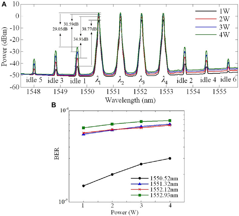
FIGURE 5. (A)The amplified spectrum of four channels. (B) The correlation between optical power and the system BER.
Conclusion
In conclusion, a novel phase lock controller, based on the large-scale power jitter compensation method, has been designed to compensate for power fluctuations ranging from 0 to 40 dB. In applying the self-designed phase lock control unit, a high-sensitivity DPSK-based multi-channel communication system was established, which realized superior receiving performance. With the data rate of a single channel as 2.5 Gbps and unencoded BER as 1 × 10⁻³, receiving sensitivity was obtained as −53.58 dBm (13.69 photons/bit), −53.59 dBm (13.66 photons/bit), −53.61 dBm (13.59 photons/bit), and −53.63 dBm (13.53 photons/bit) for each independent channel, respectively. The gap between the results of our experiment and the theoretical limit narrowed to about −3.5 dB. In addition, multi-channel communication system performance degradation caused by the FWM effect was confirmed to be negligible, which endows communication systems with the link capacity expansion potential of hundreds of Gbps in the future. As indicated by the experimentation, the self-designed phase lock controller has the stable performance and measurement precision to meet forthcoming requirements and hence has potential application for satellite-to-ground laser links.
Data availability statement
The original contributions presented in the study are included in the article/Supplementary Material, and further inquiries can be directed to the corresponding authors.
Author contributions
DG, WW, and XX conceived the idea for the study; DG and TL wrote the article; all authors discussed the results and revised the manuscript.
Funding
National Natural Science Foundation of China (61231012, 91638101); National Key Research and Development Program of China (2018YFC0307904-02); and Fundamental Research Funds for the Central Universities (xzy022021039).
Conflict of interest
The authors declare that the research was conducted in the absence of any commercial or financial relationships that could be construed as a potential conflict of interest.
Publisher’s note
All claims expressed in this article are solely those of the authors and do not necessarily represent those of their affiliated organizations, or those of the publisher, the editors, and the reviewers. Any product that may be evaluated in this article, or claim that may be made by its manufacturer, is not guaranteed or endorsed by the publisher.
References
1. Willner AE, Liu C. Perspective on using multiple orbital-angular-momentum beams for enhanced capacity in free-space optical communication links. Nanophotonics (2021) 10:225–33. doi:10.1515/nanoph-2020-0435
2. Gao D, Xie Z, Ma R, Wang W, Bai Z, Jia S, et al. Development current status and trend analysis of satellite laser communication (invited). Acta Phtonica Sin (2021) 50:9–29.
3. Su Y, Wang W, Hu X, Hu H, Huang X, Wang Y, et al. 10 Gbps DPSK transmission over free-space link in the mid-infrared. Opt Express (2018) 26:34515–28. doi:10.1364/oe.26.034515
4. Yu X, Zhang L, Zhang Y, Song Y, Tian M, Wang T, et al. 2.5 Gbps free-space optical transmission between two 5G airship floating base stations at a distance of 12 km. Opt Lett (2021) 46:2156–9. doi:10.1364/ol.419690
5. Aveta F, Refai HH, LoPresti PG. Multiple access technique in a high-speed free-space optical communication link: Independent component analysis. Opt Eng (2019) 58:036111. doi:10.1117/1.oe.58.3.036111
6. Ma Y, Lewicki R, Razeghi M, Tittel F. QEPAS based ppb-level detection of CO and N_2O using a high power CW DFB-QCL. Opt Express (2013) 21:1008–19. doi:10.1364/oe.21.001008
7. Mai VV, Kim H. Beaconless pat and adaptive beam control using variable focus lens for free-space optical communication systems. APL Photon (2021) 6:020801. doi:10.1063/5.0039108
8. Mirza J, Ghafoor S, Hussain A. All-optical generation and transmission of multiple ultrawideband signals over free space optical link. Opt Eng (2019) 58:1. doi:10.1117/1.oe.58.5.056103
9. Hamza AS, Deogun JS, Alexander DR. Classification framework for free space optical communication links and systems. IEEE Commun Surv Tutorials (2018) 21:1346–82. doi:10.1109/comst.2018.2876805
10. Dong F, Chen G, Liu Z, Lin P, Zhang Y, Ma W, et al. Low SNR difference Nyquist-WDM channels with optical sinc-shaped pulses based on flat electro-optic frequency combs. Appl Opt (2020) 59:11389–95. doi:10.1364/ao.411962
11. Ma Y, Feng W, Qiao S, Zhao Z, Gao S, Wang Y. Hollow-core anti-resonant fiber based light-induced thermoelastic spectroscopy for gas sensing. Opt Express (2022) 30:18836–44. doi:10.1364/oe.460134
12. Han X, Li P, Chang C, Gao D, Zhang D, Liao P, et al. A comprehensive comparison and analysis of several intensity modulations based on the underwater photon-counting communication system. Front Phys (2022) 9:811. doi:10.3389/fphy.2021.815343
13. Wang L, Wang J, Tang X, Chen H, Chen X. Performance analysis of a spatial diversity coherent free-space optical communication system based on optimal branch block phase correction. Opt Express (2022) 30:7854–69. doi:10.1364/oe.448956
14. Geng C, Li F, Zuo J, Liu J, Yang X, Yu T, et al. Fiber laser transceiving and wavefront aberration mitigation with adaptive distributed aperture array for free-space optical communications. Opt Lett (2020) 45:1906–9. doi:10.1364/ol.383093
15. Shin WH, Lee JW, Ha IH, Han SK. Data rate enhancement of free space optical communication using pulse positioned differential phase shift keying. Opt Express (2021) 29:26039–47. doi:10.1364/oe.435060
16. Spellmeyer NW. Use of commercially available fiber optic components in emerging space laser communications applications: Optimizing performance, cost, and reliability. In: 2021 Optical Fiber Communications Conference and Exhibition (OFC); 6–11 June 2021; Washington, DC, United States (2021). p. 1–3.
17. Araki T. Current trends in space optical communication around the world and its R&D activities in JAXA. IEICE Trans Fundamentals (2018) E101-A:161–6. doi:10.1587/transfun.e101.a.161
18. Rose TS, Klimcak CM, Kozlowski DA, Sefler GA, Yura HT, Walston AA, et al. Wavelength tracking interferometer for DPSK lasercom links. In: 2011 International Conference on Space Optical Systems and Applications (ICSOS); 11-13 May 2011; Santa Monica, CA (2011). p. 306–11.
19. Caplan DO. Laser communication transmitter and receiver design. J Optic Comm Rep (2007) 4:225–362. doi:10.1007/s10297-006-0079-z
20. Seimetz M. High-order modulation for optical fiber transmission. Berlin/Heidelberg, Germany: Springer (2009).
21. Ghassemlooy Z, Popoola W, Rajbhandari S. Optical wireless communications: System and channel modelling with matlab. Florida, United States: CRC Press (2019).
24. Elayoubi K, Rissons A, Lacan J, Antonin LS, Sotom M, Kernec AL. RZ-DPSK optical modulation for free space optical communication by satellites. In: 2017 Opto-Electronics and Communications Conference (OECC) and Photonics Global Conference (PGC); 31 July - 4 August 2017; Singapore (2017). p. 1–2.
25. Guan P., Roge K. M., Kjoller N. K., Mulvad H. C. H., Galili M., Morioka T., Oxenlowe L. K. (2015). All-optical WDM regeneration of DPSK signals using optical fourier transformation and phase sensitive amplification. 2015 European Conference on Optical Communication (ECOC), Valencia, Spain, 27 September – 1 October 2015 0228.
26. Mao Y, Liu B, Zhao D, Sun T, Zhao L, Ullah R, et al. All-optical 3R regeneration for DPSK signal based on a semiconductor optical amplifier scheme. Appl Opt (2020) 59:3526–9. doi:10.1364/ao.389952
Keywords: free-space optical communication, differential phase shift keying, delay line interferometer, phase lock controller, wavelength division multiplexing
Citation: Gao D, Li T, Xie Z, Meng J, Jia S, Bai Z, Wang W and Xie X (2022) High-sensitivity multi-channel DPSK system with real-time phase lock controller for free-space optical communication. Front. Phys. 10:971919. doi: 10.3389/fphy.2022.971919
Received: 17 June 2022; Accepted: 18 July 2022;
Published: 29 August 2022.
Edited by:
Yufei Ma, Harbin Institute of Technology, ChinaReviewed by:
Siyuan Yu, Harbin Institute of Technology, ChinaHongzhan Liu, South China Normal University, China
Tianshu Wang, Changchun University of Science and Technology, China
Copyright © 2022 Gao, Li, Xie, Meng, Jia, Bai, Wang and Xie. This is an open-access article distributed under the terms of the Creative Commons Attribution License (CC BY). The use, distribution or reproduction in other forums is permitted, provided the original author(s) and the copyright owner(s) are credited and that the original publication in this journal is cited, in accordance with accepted academic practice. No use, distribution or reproduction is permitted which does not comply with these terms.
*Correspondence: Wei Wang, wangwei2012@opt.ac.cn; Xiaoping Xie, xxp@opt.ac.cn
†These authors have contributed equally to this work and share first authorship