State-of-the-art challenges and emerging technologies in radiation detection for nuclear medicine imaging: A review
 Emily Enlow
 Shiva Abbaszadeh
- Radiological Instrumentation Laboratory, University of California, Electrical and Computer Engineering, Santa Cruz, CA, United States
Single photon emission computed tomography (SPECT) and positron emission tomography (PET) are established medical imaging modalities that have been implemented for decades, but improvements in detector design and camera electronics are needed for advancement of both imaging technologies. Detectors are arguably the most important aspect of the systems. Similar to SPECT, PET typically relies on indirect conversion of gamma radiation via scintillators coupled with photosensors used to convert optical photons produced by the scintillator into an electrical signal. PET detectors are defined by their energy resolution, timing resolution, and spatial resolution, all of which affect and determine the image quality. Improvements in energy resolution have been shown by increasing the brightness of the scintillator utilizing materials like cerium bromide (CeBr3) or switching to a direct conversion detector, such as cadmium zinc telluride (CZT) or thallium bromide (TlBr). Timing resolution for PET is a focal point of the current research. Improving the timing resolution improves the signal-to-noise of the PET system and is integral to the implementation of time-of-flight PET. By utilizing novel configurations, such as side readouts on scintillators, timing resolution has been improved dramatically. Similarly, metascintillators, which use complex combinations for the scintillator material, have also shown improvements to the timing resolution. Additional research has focused on using Cherenkov light emission in scintillators to further improve the timing resolution. Other research is focused on using convolutional neural networks and other signal processing to enhance timing resolution. Lastly, aside from acollinearity and positron range, spatial resolution is impacted by the PET detector, therefore improving the intrinsic spatial resolution of the detector will allow for smaller features to be imaged. One method for improving the spatial resolution is to use unique configurations with layered scintillators. Additionally, monolithic scintillators have also been shown to have reduced spatial resolution. The future for both SPECT and PET image system advancement will depend on continued development of the detectors via many different pathways including materials, signal processing, physics, and novel configurations. In this review article, we will discuss challenges and emerging technologies for state-of-the-art radiation detectors utilized in PET and SPECT.
1 Introduction
Single photon emission computed tomography (SPECT) and positron emission tomography (PET) are important nuclear imaging modalities that have become integral parts of patient diagnosis and care in the past several decades. SPECT detects a single high-energy photon from an injected radio-tracer. SPECT systems have a wide range of uses in the clinical setting, including skeletal imaging, cardiac perfusion assessment, thyroid imaging, and dosimetry in radionuclide therapy [1–3]. Typically, SPECT systems are based on the Anger camera which consists of a collimator, scintillator, photosensor, and readout electronics; Figure 1 shows the basic set-up of a SPECT detector. The scintillator of choice for SPECT is typically sodium iodide, NaI. Some modern SPECT systems have begun to move away from the indirect photo-conversion mechanism of scintillator crystals towards the direct gamma conversion in semiconductors such as cadmium zinc telluride (CZT). Most SPECT systems have a dual-head detector that can be moved around the patient. A limiting factor in SPECT detector design is the absorptive collimator which only allows a fraction of the incident radiation to pass through it [5–8].
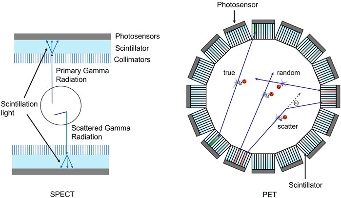
FIGURE 1. SPECT basic set-up comprising of photosensors, scintillators, and collimators in a dual head system both primary and scattered gamma radiation is allowed through the collimator and produces scintillator light in the scintillator crystal (left). PET basic set-up comprising of photosensors and scintillators surrounding the subject (right). Reproduced under CC-BY 4.0 license from [4].
For PET, the injected radio-tracer emits a positron that annihilates with an electron, releasing two simultaneous 511 keV photons. These annihilation photons are measured in the PET detector and with enough coincident events, an image is constructed. PET imaging systems typically consist of a scintillator, photosensor, and readout electronics. Figure 1 shows the basic PET system set-up with a scintillator and photosensor labeled. Many commercial PET systems have successfully transitioned from photomultiplier tubes (PMTs) to silicon photomultiplier (SiPMs). Converting from PMTs to SiPMs allows for much faster timing for the PET scanners, improving timing resolutions from nanoseconds to the range of 214–380 ps[9]. The industry standard currently uses lutetium (Lu)-based scintillators such as lutetium oxyorthosilicate (LSO) and lutetium-yttrium oxyorthosilicate (LYSO) [7, 8, 10, 11].
The signal-to-noise ratio (SNR) in PET is dependent on the dose, scan time, and system sensitivity. It is desirable to keep the dose and scan time as small as possible, so improving the sensitivity of the PET system is a major driving factor for PET research and development [4]. SNR in PET systems is proportional to the square root of the number of events detected, n. The number of detected events can be approximated using Eq. 1:
where A is the activity in the field of view (FOV) of the scanner, G is the geometric coverage of the scanner, T is the acquisition time, ε is the efficiency of the detector for detecting 511 keV photons, and k incorporates patient-specific parameters such as attenuation and scattering [10].
Sensitivity is defined as the smallest concentration of the radiotracer that can be detected. Sensitivity of the PET system is affected by the scintillation crystal thickness, axial FOV, gaps between modules, and ring diameter [12]. Reducing the ring diameter can be used as a solution to improve sensitivity, but a smaller scanner diameter will limit the patient population. Organ dedicated and preclinical systems have shown promise in reducing the aperture size to improve sensitivity. Preclinical systems are focused on small animal imaging for research, so the ring diameter can be reduced considerably compared to clinical PET [13–15]. Spatial resolutions of 0.4 mm–0.6 mm have been shown in preclinical systems using pixelated scintillators [14]. Research is also being conducted on organ specific PET systems that will allow for a reduction in ring diameter. Specialized systems for head and breast are utilized to improve the spatial resolution while increasing the SNR [10, 16]. Increasing the scintillation crystal length has proved to be an effective method to increase sensitivity, but this often will reduce the spatial resolution due to parallax errors [10]. Total body PET systems use a long axial FOV to improve sensitivity dramatically [17]. These systems will be discussed later.
Another key characteristic of PET systems is spatial resolution. Spatial resolution is fundamentally limited by several factors but when focusing on the detector characteristics it is important to consider the geometry of the detector, depth of interaction (DOI), and the detector sensitivity to 511 keV photons. Detector materials must have a high density and atomic number such that a high density of electrons can interact with the annihilation photons. Energy and timing resolutions must be acceptably good so that the coincidence events can be distinguished from the scattered events and random coincidences [10, 18, 19].
Scattered events occur when one or both annihilation photons scatter within the tissue of the subject. This scattering causes the photons to no longer be collinear with the emission point and can cause an incorrect line of response (LOR) which results in degradation of the image quality. Figure 1 also shows the scattering, random events, and true events that are common for PET, and the scattering events that occur in SPECT. If the energy resolution is sufficiently high, the scattered events can be eliminated as the energy is lower than the expected photopeak energy. Random events occur when two non-coincident photons are detected in a small time window. If the timing resolution is very high, the random events will be reduced [7, 8, 20].
There are two primary types of detectors used in PET and SPECT: indirect and direct. Indirect detectors use scintillators to convert incident gamma radiation to down converted photons, generally in the ultra violet-visible-near infrared spectrum. Direct detectors use semiconductors to convert incident radiation into electrons and holes.
2 Light readout
Scintillators convert the high energy photons from radio-tracers in the subject into optical photons. These optical photons need to be converted into an electrical signal to extract the energy and time data for image reconstruction, so a photosensor is typically used to couple to the scintillator. It is important that these photosensors have high photon detection efficiency (PDE) and charge amplification in order to generate a measurable electronic signal. Both PET and SPECT depend on good energy resolution of their detectors, and the photosensor can play a pivotal role in improving energy resolution. For PET systems, timing is an important consideration, so the photosensors should have sub-nano second rise times [21–23]. Additional considerations for photosensors are the refractive index matching and the reduction of dead space [20, 24, 25].
PMTs have been the standard photosensor for PET and SPECT scintillators since the beginning. The PMT signal can be amplified up to 106 to 108 [24, 25]. The PDE of PMTs typically ranges from 25% to 43%. PMTs have a low dark count rate and also a short signal rise time. TOF-PET systems using PMTs and LYSO scintillators typically have a timing resolution ranging from 400 to 700 ps for the system [24].
Solid state photosensors have begun to replace the PMT for the photosensor for SPECT and PET detectors. Some advantages of these photosensors are functionality in magnetic fields, compact design and fabrication, and rugged design. There are two primary types of solid state photosensors used in PET and SPECT: avalanche photodiodes (APDs) and SiPMs. APDs have a large reverse bias applied to the diode, which causes the electrons produced by the photons to be accelerated. This fast moving electron collides with the lattice to create an electron-hole pair. The reverse bias continues to accelerate these electrons, causing more electron-hole pairs to be generated creating an avalanche effect. This results in signal amplification, but the gain of this system is only around 100 to 1,000, significantly lower than the PMT gains [20, 24]. APDs have PDEs that can be above 90%, but the rise time is 10 ns due to the diode capacitance [24].
SiPMs have emerged as a promising new photosensor for TOF-PET. In addition to the previously mentioned benefits of solid state photosensors, SiPMs have a high PDE, fast response, and high gain [24, 25]. There are two main types of SiPMs: analog and digital. SiPMs are constructed of an array of parallel APDs operated above the breakdown voltage. These APDs operated in this way are called single photon avalanche diodes (SPADs). The gain of an SPAD ranges from 105 to 107, which is comparable to PMTs and considerably higher than APDs [24, 25]. To construct a SiPM, the number of SPADs must be larger than the number of photons to detect. This will make the SiPM signal proportional to the number of photons. If there are more photons than SPADs, as is the case of a bright scintillator, proportionality will be lost, and a non-linear correction will need to be implemented. Analog SiPMs output this signal from the scintillator light as an analog signal that will later need to be digitized to get the energy and timing information. Digital SiPMs utilize counting electronics, so the output is the number of SPADs that measured a photon [25].
3 Energy resolution improvement
Accurate measurement of the energy of the photons emitted from the subject is important for SPECT and PET due to the high likelihood of scattering in human tissue. The energy resolution of a detector defines the ability of the detector to discriminate between different deposited energies. Improving the energy resolution allows better rejection of scattered photons, which enhances image contrast while still allowing for high counts of the photopeak energy. Energy resolution is mathematically defined as the full-width half maximum (FWHM) of the energy peak divided by the energy of the unscattered photon [26]. Energy resolution limitations for detector material can be approximated using the Poisson limited resolution from Eq. 2 [27]:
where N is the number of carriers, and F is the Fano factor for the material, which is an intrinsic material constant that reflects the detector resolution. The Fano factor is typically less than one for semiconductors, with CZT having a Fano factor of 0.089 ± 0.005 [28, 29]. The Fano factor for scintillators depends on the free electron and hole statistics, conversion efficiency to optical photons, and non-proportionality [30]. Given these dependencies, the Fano factor for scintillators can have a large range depending on their properties, but typically scintillators are consistent with Poisson statistics and will have Fano factors close to one [29]. The number of carriers produced by gamma-ray absorption is also a material property [27]. It is apparent from this equation that improving the energy resolution can be achieved by informed detector material selection.
3.1 Scintillator detectors
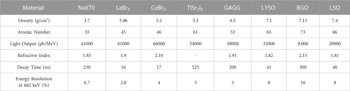
Many materials have been researched as potential scintillators for SPECT and PET. Table 1 gives some of the important material properties of various scintillators. High effective atomic number and density are important for scintillator materials to ensure the scintillators have a high enough stopping power to convert high-energy photons to scintillation photons.
Beyond the limitation of the detector material shown in Eq. 2, there are also other constraints on the energy resolution that need to be considered for scintillators [27],
where RnPr is the effect of the detector non-proportionality, Rinh is the effect of inhomogeneous defects which could cause issues with light output, RP is the transfer resolution, and RM is the energy resolution from the photosensor and Poisson statistics. In cases with homogeneous crystals, the values for Rinh and RP are considered to be less than 1% [27, 41]. The effect of RM can be improved by using high photon PDE SiPMs to improve the energy resolution issues caused by poor conversion of PMTs. Bismuth germanate (BGO) was the scintillator material of choice for several years prior to the 1990s due to the high stopping power, but the poor light output of 9,000 ph/MeV leads to energy resolutions of 10% at 662 keV [31, 42].
From Eq. 2, it is clear that increasing the light output of the scintillator will improve the energy resolution of the detector. Current PET detectors use Lu-based scintillators which generate approximately 30,000 photons/MeV resulting in an energy resolution of 7.6% at 662 keV [26]. These Lu-based scintillators have an increase in background radiation caused by the 176Lu decay that occurs within the scintillator [43]. Lutetium fine silicate (LFS) scintillators have a light output of 38,000 photons/MeV with a resulting energy resolution of 13% at 511 keV [44, 45]. SPECT systems typically use NaI(Tl) which generates 41,000 photons/MeV in the 325–550 nm spectrum. Halide scintillators, such as cerium bromide (CeBr3), have exhibited light output of 66,000 photons/MeV which is two times more than the light output compared to Lu-based scintillators, which improves the energy resolution from 8% for LYSO to 4% for CeBr3 at 662 keV [32]. In addition to halide scintillators, gadolinium aluminum gallium garnet scintillators (GAGG) have also shown promise in improving energy resolution by increasing the light output to 58,000 photons/MeV, resulting in an energy resolution of 5% at 662 keV [33]. Thallium strontium iodide (TlSr2I5) is a new scintillator detector material that has shown promise with an energy resolution of less than 3% at 662 keV due to the high light yield of 54,000 photons/MeV [34]. Lanthanum bromide (LaBr3) scintillators have a high light output of 61,000 ph/MeV resulting in an energy resolution of 2.8% at 662 keV, but have found limited use in PET and SPECT due to stability issues in ambient conditions [35, 36].
Non-proportionality can cause light output to fluctuate based on the excitation energy. Halide scintillators have increasing light output with decreasing excitation energy, but oxides have a tendency to have decreasing light output with decreasing excitation energy [42]. Because of this trend in oxides, LSO and other similar scintillators have much worse energy resolutions at lower energies. Scintillators such as lutetium perovskites (LuAP) and lutetium aluminum perovskite (LuYAP) have shown lower light outputs than LSO, but due to the better non-proportionality these scintillators have energy resolutions comparable to LSO [42]. Other important properties of scintillator crystals for radiation detection are: mature production processes, chemical durability, stability in ambient conditions, and long lifetime in high radiation environments.
3.2 Semiconductor detectors
Semiconductor detectors directly convert radiation photons into an electrical signal by absorbing the photons and generating electron-hole pairs. By applying a voltage bias across the semiconductor, the electrons and holes are attracted to the different electrodes, inducing a current on the electrodes. The charge carriers have less spatial dispersion than typically isotropic light distribution in scintillators and the reduced size of the electrodes leads to improved spatial resolution. The energy of the photon is directly proportional to the total induced charge on each electrode. Semiconductor detectors have higher energy resolution due to this direct conversion when compared to scintillation detectors [46, 47].
The mobility-lifetime products for electrons and holes, µτe and µτh, of the semiconductor are very important, as they dictate the mean drift length which is the average distance a charge carrier can travel before being captured by traps or recombination centers. The energy required to create an electron-hole pair in the material is another important parameter and is proportional to the bandgap [37]. Both of these characteristics affect the number of carriers generated in the detector which is directly related to improving the energy resolution of the detector per Eq. 2.
The semiconductor material must have a large bandgap so that the detector can be operated at room temperature with low leakage current. The semiconductor must also have a high effective atomic number and density to have sufficient stopping power for the high-energy photons, similar to scintillator detectors. The probability that a high-energy photon will interact with a material via photoelectric absorption is directly proportional to Zn, where n is between 4 and 5 over an energy range of 0.1 MeV–3 MeV [29, 46, 48]. The probability of Compton scattering is directly proportional to Z [29, 46, 48].
Semiconductor detectors have shown sub-millimeter spatial resolutions and improved energy resolutions. Anode and cathode configurations can allow for position sensing of individual photon interactions, thus giving DOI information. This improved position sensing combined with the energy resolution can lead to improved sensitivity. Development of semiconductor detectors for high-energy photons has been ongoing for many years, and some commercial SPECT systems have implemented this technology successfully. However, there are still no clinical PET systems that use direct conversion detectors because of the poor timing resolution of the semiconductor detectors. Table 2 shows material properties for some of the standout semiconductor materials for both PET and SPECT.
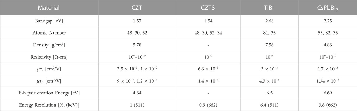
TABLE 2. Material properties for various semiconductor materials for radiation detection [37, 49–55].
CZT has been the popular and standout semiconductor for radiation detection for more than 3 decades. The effective atomic number, density, and bandgap have allowed for room temperature detection while the resistivity is high enough to limit leakage current. Energy resolutions for CZT detectors have been measured to be 1% at 511 keV for different CZT systems [49]. A 40 mm by 40 mm large scale CZT detector has achieved an energy resolution of 1% at 662 keV with a single pixel energy resolution of 0.7% at 662 keV [56].
While the process for fabricating CZT has been improved over the last 3 decades, there are still major issues with defects. Sub-grain boundary networks and Te inclusions are two defects that can limit the performance of CZT. In addition to lowering performance, these fabrication issues also increase the cost of CZT due to poor yields of high-quality crystals for detectors [57]. One possible solution to limit the occurrence of these defects is including selenium (Se) in the CZT detector to make cadmium zinc telluride selenium (CZTS). By adding Se, the compositional homogeneity of the semiconductor was increased, sub-grain boundaries were eliminated, and Te inclusions were reduced by an order of magnitude [58, 59]. The overall growth yield for CZTS has been shown to increase to 90% compared to 33% for CZT [60, 61]. In addition to increasing the production yield, reducing defects also improves the energy resolution of the detector. An energy resolution of 0.9% at 662 keV has been shown on crystals grown via a traveling heater method with Frisch collar [61, 62].
Other semiconductors that have been of interest for radiation detection are the thallium halides, namely, thallium bromide (TlBr). These materials have impressive stopping power due to their high atomic numbers and densities, but poor mobility-lifetime products has resulted in limited use in radiation detection. In the past decade, new fabrication methods for TlBr have improved the charge transport characteristics. It has been shown that there is a strong relationship between purity and mobility-lifetime product with increases up to 2 orders of magnitude measured [50, 51], and recently electron mobility-lifetime products have been increased to 3 × 10⁻³ cm2/V. Hole mobility-lifetime products have also been increased to 4.3 × 10⁻⁵ cm2/V, which makes the charge transport characteristics of TlBr comparable to CZT. Energy resolutions for TlBr detectors have also been reported as 6.4% at 511 keV on less than 1 mm thick detectors [52]. Additionally, 5 mm thick TlBr detectors have been shown to have 2.85% ± 0.88% at 662 keV [63].
An emerging class of materials for radiation detection is metal halide perovskites such as cesium lead bromide (CsPbBr3), methylammonium lead bromide chloride (MAPbBrxCl(1-x)), and methylammonium lead iodide (MAPbI3). These optoelectronic materials have garnered much interest in the area of photovoltaics and light-emitting diodes, but have also shown promise in the direct conversion of gamma radiation. Perovskites have low formation energies which allow for cost-effective crystal growth. The mobility-lifetime products of CsPbBr3 have been shown to be comparable to CZT. Energy resolutions of 3.8% at 662 keV have been demonstrated [53, 54].
A known limitation for direct detectors is poor timing resolution. This is caused by the electrical signal being produced by the charge carriers moving through the semiconductor material and is limited by how quickly the carrier moves through the material. These carriers are slower and have a larger fluctuation when compared to photons moving through a medium.
4 Time resolution improvement for time-of-flight measurements
The time resolution for PET detectors is a critical feature. When the positron annihilates with an electron, two coincident 511 keV photons are emitted from the positron decay. The scanner must measure the arrival time of these annihilation photons at two different detectors with enough accuracy that the coincidence can be confirmed. This creates a LOR between the two detectors. After a large number of LORs have been established, an image can be reconstructed. The positioning of the positron annihilation has some uncertainty Δx that is dependent on the timing resolution, Δt, using Eq. 4:
where c is the speed of light in vacuum [7]. If Δt is small enough, on the scale of picoseconds, the location of the annihilation can be reduced along the LOR to a weighted Gaussian as shown in Figure 2. This is considered time-of-flight (TOF) PET. If the timing resolution can be reduced to 10 ps, image reconstruction may no longer be needed, since the probability function of the LOR will be reduced to a single voxel [64]. Eq. 5 demonstrates the improvement in SNR when TOF PET is used rather than traditional PET:
were D is the diameter of the scanner ring, c is the speed of light in vacuum, and Δt is the timing resolution [7, 19]. As the timing resolution gets smaller, the SNR ratio of TOF will improve. Current commercial systems on the market have achieved TOF with timing resolutions down to 214 ps by using Lu-based scintillators and SiPMs for photosensors, but there is still much research pushing toward the 10 ps resolution to reduce the amount of image reconstruction needed [9, 64, 65].
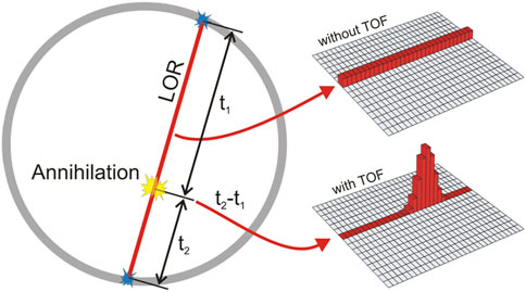
FIGURE 2. LOR for traditional (non-TOF) PET and TOF-PET. The probability of the annihilation location without TOF is uniform across the LOR. Using TOF, the probability can now be adjusted to find the most likely location of the annihilation. Reproduced under CC-BY 4.0 license from [4].
4.1 Detector configuration
Commercial PET scintillators are made up of long, narrow crystals that are coupled to photosensors at the end of the scintillator. For fast timing, the photosensors of choice are SiPMs, which allows for faster response than photomultiplier tubes (PMTs) [7, 26]. The scintillator crystals in these detectors need to be sufficiently long to ensure 511 keV photon interaction occurs, but the extended length increases the transit time of the photons which worsens the timing resolution of the detector [66]. There are a few different detector configurations that can be used beyond the traditional single-ended photosensor coupled to the end of the scintillator crystal. Figure 3A shows an example of a typical single-ended detector configuration with a photosensor attached to the bottom of the scintillator.
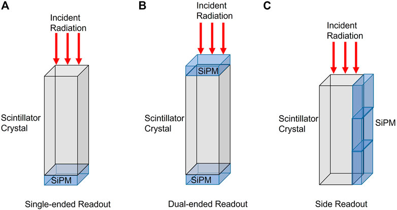
FIGURE 3. Different configurations for PET detector photosensor coupling. (A) Single-ended readout, (B) Dual-ended readout, (C) Side readout.
Dual-ended readouts have photosensors on the top and bottom of the scintillator as shown in Figure 3B and have also been employed for timing resolution improvement. The effects of surface condition, enhance specular reflector material, and dual-ended readout have been investigated by many groups [67–71]. In studies by Kang et al, the optimum configuration was found to be a saw-cut LYSO surface condition with air as the specular reflector material. The specular reflector material helps with limiting light loss in the scintillator and increasing light collection. The single-ended configuration had a timing resolution of 349 ± 22 ps The dual-ended configuration showed a DOI resolution of 2.9 ± 0.2 mm while also improving the timing resolution significantly to 188 ± 32 ps[67]. Dual-ended readouts have also been used with an axial orientation where the radiation is incident on the longer side of the scintillator rather than the smaller end. This design has been used by various groups [72–75].
A method for improving timing resolution with these scintillators is to employ a side readout function shown in Figure 3C where the photosensor is coupled to the long side of the scintillator crystal instead of the bottom. This configuration offers more accurate position of one or more annihilation photon interactions, estimates the incident angle of the annihilation photon to increase sensitivity, and gives ultra-precise positioning to determine the end points of the LOR. It has been shown that employing a side readout allows for almost complete light collection while also reducing the transit time for the photons to the photosensors [66]. A 2.9 × 2.9 × 20 cm3 lutetium-gadolinium oxyorthosilicate doped with cerium (LGSO:Ce) scintillators with SiPMs for both bottom readout and side readout were constructed to compare the timing response based on readout location. The timing response for the bottom readout scintillator was 137 ± 3 ps and the side readout showed an improved timing resolution of 102 ± 2 ps[66]. A downside of these novel detector configurations is the increase in the number of photosensors and an increase in complexity of the readout electronics [25].
4.2 Cherenkov radiation
Cherenkov radiation occurs when subatomic particles travel faster than the phase velocity in a medium. Upon material relaxation, photons are emitted at an angle depending on the speed of the particles and the refractive index. This happens instantaneously, on the timescale of a few ps. The threshold for Cherenkov radiation to occur is the phase velocity of the medium which will decrease with increasing refractive index. Using these prompt photons for timing has become an increasingly popular area of research to improve the timing for PET detectors [76–83].
A challenge for using Cherenkov for timing of detectors is the limited number of photons emitted. Typically this is on the scale of 10–30 photons per 511 keV photon for a good detector material. In addition to a limited number of Cherenkov photons available, collecting the photons can also be difficult as the photons can be absorbed by the material or lost to surface conditions. It is also of utmost importance that the photosensor has a high conversion efficiency and a very good single photon time response (SPTR), so that the small number of photons are collected instead of lost due to poor photosensor efficiency [79]. SiPMs with enhanced UV detection efficiency are also important for measuring the Cherenkov photons as the wavelengths of these photons can be in the UV range, and the limited number of Cherenkov photons produced means the SiPM detection efficiency is vital [78, 79].
The desired properties of a Cherenkov detector are high transparency over a wide range of wavelengths, high refractive index, and high stopping power for high-energy photon detection. There are two types of Cherenkov materials for detectors: scintillators and semiconductors. Both of these detectors act on the fast photon response of Cherenkov radiation to determine the timing of the photon absorption. After the Cherenkov response, the scintillators have a slower photon absorption signal which can be used to find the energy of the gamma photon. Semiconductor detectors convert the high energy photon into electrons and holes, the timing response of semiconductor detectors is typically much slower than the timing response of scintillators due to the mobility of electrons and holes in the semiconductor material.
By utilizing Cherenkov radiation, improved timing resolutions are realized because the emission of Cherenkov photons is on the timescale of 10 ps[64]. By combining Cherenkov photons with scintillation or direct conversion semiconductors, timing can be improved while maintaining energy resolution [64, 76]. An additional advantage of Cherenkov materials is they are typically less expensive and have less expensive manufacturing costs. There are several challenges with using Cherenkov radiation which include the need for very sensitive photosensors with fast readout electronics so the fast, but few Cherenkov photons can be measured. Data processing methods also need to be developed to improve the timing response further [77].
There are a wide variety of materials that exhibit Cherenkov radiation, and many of these materials have been used in previous radiation detector designs, but with the advances in photosensor collection, Cherenkov photons can now be measured before scintillation photons for improved timing for established scintillators, such as BGO. BGO had been the primary scintillator for PET systems, but due to the poor timing resolutions, they were eventually phased out to make way for faster scintillators. Advantages of BGO are the reduced cost and better stopping power. BGO costs one-third less than LYSO, so using BGO could reduce instrumentation costs significantly [84]. The stopping power of BGO results in better detection efficiency which improves the sensitivity [78]. BGO has an index of refraction of 2.15, and this high index of refraction correlates to the number of Cherenkov photons that will be produced in the material [78]. The Cherenkov yield for BGO is expected to be 17 ± 3 photons [80]. For a 3 × 3 × 15 mm3 BGO crystal, timing resolution was improved to 189 ± 8 ps compared to a conventional BGO scintillator timing of 800 ± 9 ps[77].
Thallium halide semiconductors have been shown to exhibit Cherenkov radiation and also have high densities, high atomic numbers, and wide bandgaps which relates to effective stopping power for radiation detectors. TlBr semiconductor detectors have shown impressive energy resolutions, but the timing resolution is typically on the scale of nanoseconds which is far too slow for TOF PET. Since these semiconductors exhibit Cherenkov emission, the hope is that the timing resolution can be improved by measuring these prompt photons before the electrons and holes move through the material. TlBr has a high refractive index of 2.48 which is larger than BGO, so the number of Cherenkov photons is expected to be increased. The timing resolution for a 3 × 3 × 20 mm3 crystal was found to be 289 ± 9 ps[81]. A comparison between TlBr and thallium chloride (TlCl) has also been conducted and it was discovered the TlCl had a higher emission and detection of Cherenkov photons. Figure 4 shows how the timing resolution will decrease from over 400 ps and 500 ps for TlBr and TlCl, respectively, to around 300 ps for both semiconductors with increasing Cherenkov photon detection [85]. In order to maintain the high energy resolution with the use of Cherenkov photons, these detectors will need to use two different readout methods to measure the induced charge and the Cherenkov photons. This increases the complexity of the detector significantly [76].
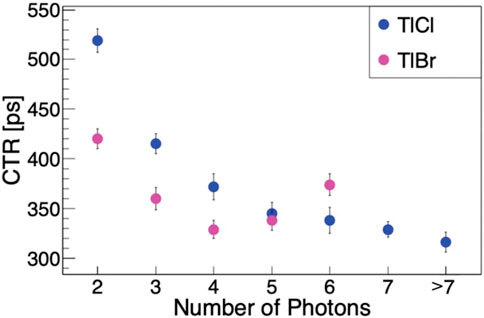
FIGURE 4. Comparison of the time resolution for TlBr (pink) and TlCl (blue) as a function of detected Cherenkov photons. Ⓒ[2020] IEEE. Reprinted, with permission, from [85].
4.3 Metascintillators and polymer scintillators
For scintillator materials, there is an inherent trade-off between efficient radiation detection and photon kinetics. To overcome this trade-off, composite scintillators, called metascintillators or heteroscintillators, have been explored to increase the radiation detection efficiency while maintaining desired photon kinetics within the scintillator [86].
Inorganic scintillator materials, such as BGO and LYSO, have high densities and atomic numbers which means they have good stopping power for high-energy photons. These scintillators need to be approximately 20 mm long to ensure conversion of high-energy photons to scintillator photons. BGO has worse timing characteristics than LYSO which is a reason commercial products have stepped away from BGO scintillators, replacing them with Lu-based scintillators, which can cost up to three times as much [84]. There has been a recent push to find methods to improve the timing resolution of BGO for the development of a cost effective TOF PET detector. Polymer scintillators, like EJ232, have prompt photon emission but poor stopping power. Several configurations of BGO, LYSO, EJ232, and barium fluoride (BaF2) have been considered for TOF improvement [86–88]. BaF2 is a scintillator material that exhibits a fast and slow scintillator emission, which has been shown to be comparable to organic scintillators [89]. The proposed scintillators, shown in Figure 5 are layered inorganic composite structures, incorporating the slow materials of BGO or LYSO (dense host material) with faster EJ323 and BaF2 (fast emitter). The pixel size for these metascintillators was 3 × 3 × 15 mm3. The bulk BGO 3 × 3 × 15 mm3 crystal had a timing resolution of 400 ps, the EJ232 had an estimated timing resolution of 100 ps, and a 3 × 3 × 15 mm3 crystal of BaF2 had a timing resolution of 100 ps? By combining BGO with EJ232 or BaF2 in a layered scintillator, it was found that the timing resolution was 205 ps for EJ232 and 241 ps for BaF2 [87]. More work in this area needs to be done to confirm the appropriate length of the scintillators, as the polymer layers have a lower stopping power than the inorganic materials.
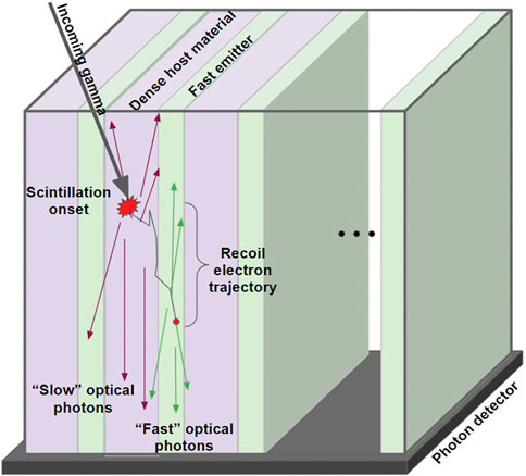
FIGURE 5. Layered composite scintillator consisting of a dense host material (purple) such as BGO or LYSO alternated with a fast emitter (green) such as EJ232 or BaF2. Reproduced under CC-BY 4.0 license from [90].
Another development with polymer scintillators is the Jagiellonian-PET (J-PET) system. This system uses BC-420 plastic scintillators with dimensions of 5 × 19 × 300 mm3. The scintillator is coupled to PMTs on both ends of the longest dimension. The length of the scintillator dictates the axial FOV, so the J-PET can be scaled up to a total body PET system with only the increased length of the scintillator, so the cost is significantly lower than typical systems discussed later [91]. Since the density of the plastic is so low, the probability of photoelectric effect is low, and the detection probability is much lower than inorganic scintillators. For these scintillators, the detection of 511 keV photons is done via Compton scattering, which means the deposited energy will change from event to event [92]. BC-420 has fast timing with a 0.5 ns rise time and a 1.8 ns day time which is considerably better than the LSO scintillator decay time of 40 ns[93]. Because of the timing characteristics of the plastic scintillator, a time over threshold measurement is used rather than a charge measurement for electronic signal processing. Signals are probed at different thresholds at the rising and falling edge. This sampling improves the ability to determine the time and place of the event. To achieve the best timing resolution, the PMTs were replaced by an array of SiPMs. For the 30 cm long scintillators, the timing resolution was 266 ps When the scintillator length was increased to 100 cm, the timing resolution was found to be 365 ns[94].
4.4 Optical property modulation
There is an intrinsic limitation of about 10 ps time resolution for scintillation due to the statistical fluctuations in the generation of scintillation photons [95, 96]. One proposed method to improve the time resolution of PET systems is via optical property modulation. This method utilizes the Pockels effect to modulate the refractive index of the detector, or Pockels cell, when an interaction between the crystal and ionizing radiation photons occurs. The experimental set up for utilizing the Pockels effect involves a polarized probe laser pumped through a crystal with an applied bias to another polarizer. The light is then focused onto a photodiode via a lens [96, 97]. The refractive index of a Pockels cell is found from Eq. 6:
where n(E) is the refractive index of the Pockels cell, E is the applied electric field, n0 is the refractive index without applying an electric field, and γ is the Pockels effect coefficient [96, 97]. In addition to the modification of the refractive index, the transmitted light intensity is also dependent on the applied electric field. This relationship is shown in Eq. 7:
where I is the intensity of the light transmitted, I0 is the maximum intensity of light transmitted, d is the path length of light, or approximately the thickness of the detector crystal, λ is the wavelength of the probe laser, and n(E), γ, and E are as described above. Charge carriers are generated within the detector crystal when high energy photons are absorbed. By applying a bias to the detector crystal, the charges drift to the different electrodes, which causes a small electric field in opposition to the applied field. This change in electric field affects the refractive index using Eq. 6, and the transmitted light changes using Eq. 7. The photodiode can then measure the change in transmitted light to measure the modulation of the optical properties of the detector crystal [95–97].
This method has been completed with various materials, such as cadmium telluride (CdTe) [96–98], bismuth silicate [98], yttrium aluminum garnet (YAG) [99], lead bismuth gallium (PbBiGa) [98], and lithium niobate (LiNbO3) [96]. Empirical analysis has predicted improvement in the timing resolution on the order of 1 ps [99]. Improving the sensitivity of the detectors using the Pockels effect is needed before experimental data can be measured [97].
4.5 Advanced signal processing
While much work has gone into the material and electronics aspect of the detector for improving the timing resolution, signal processing, which also plays a vital role, has received attention through several advancements. Signal processing has primarily used either leading edge discrimination or constant fraction discrimination for timing pick-off. These methods were selected due to the analog electronics used for processing. With more modern, fast waveform digitizers, more advanced signal processing can be implemented [100–102].
Maximum likelihood interaction time estimation is a method designed to extract the time of interaction using several time stamps from the scintillation event. For application of this method, LSO monolithic scintillators of varying size with digital SiPM arrays were used to investigate the effect on timing resolution. For scintillators with a length of 20 mm, the timing resolution was found to be 185 ps which is an improvement from 290 ps for a similarly sized scintillator without using maximum likelihood interaction time estimation [103].
Multiple groups have shown improved timing resolution by implementing convolutional neural networks (CNN) in place of the traditional leading edge signal processing [104–106]. CNN uses convolutional layers in stacks to learn features from a known input. For the PET system, the input to the CNN is the time-varying waveforms from two detectors after a coincident event is detected. The output is the time-of-flight for the event. CNN offers a unique solution to utilizing the rising edge information to understand patterns in the timing and physical factors with little modeling required. By applying a 6-layer tapered CNN the timing resolution was reported at 185 ± 2 ps demonstrating an improvement over leading edge discrimination (231 ± 3 ps) and constant fraction discrimination (242 ± 4 ps) [100].
4.6 Gas detectors
Resistive plate chambers (RPCs) are a type of gas detector made of two layers of resistive plates with a gas gap between the plates. Electrons and ions are generated when radiation passes into the gas gap. These generated electrons and ions create the output signal [107]. Gas detectors for high energy detection have good timing and spatial resolution with lower manufacturing costs compared to traditional scintillators. The main reason they are not more prevalent in industry and research is low detection efficiency [108]. A method to improve the efficiency is to increase the layers of the gas detector, so that more high energy photons are absorbed by the detector [109]. TOF-PET systems have been proposed using gas detectors [108–110].
Utilizing liquid Xenon in a gas detector has also been implemented for use in TOF-PET and Compton camera systems. Positron Emission TOF Apparatus with Liquid XenOn (PETALO) is a PET scanner that uses liquid Xenon as a scintillation material coupled to SiPMs for readout. One advantage of using a liquid as a scintillator is the possibility of using a continuous scintillator rather than using many smaller crystals [111]. Additionally, liquid Xenon has been used in a monolithic Compton camera with the ability to simultaneously detect three γ rays emitted from Scandium-44 [112].
5 Spatial resolution
In PET, spatial resolution is predominately limited by the detector size and intrinsic detector resolution, while positron range and acollinearity also play a limiting factor in the resolution [13]. Positron range is defined by the distance the positron travels before annihilating with an electron to emit two coincident 511 keV photons. The type of radio-tracer can affect this positron range. Blurring occurs due to this positron range because the positron emission occurs some distance from the radio-tracer. Acollinearity causes blurring of the image due to the annihilation photons emission not being 180o. The system resolution is defined in Eq. 8:
where Rsys is the system resolution, Rdet is the detector resolution, Rrange is the mean positron range which is dependent on the radio-tracer, and R180o is the acollinearity dependence which is approximately 0.0044 times the radius of the system [18, 20]. Beyond these physical limitations for the spatial resolution, data analysis and the reconstruction process will also have an effect on the spatial resolution of these systems [7].
5.1 Semiconductor detectors for spatial resolution
Beyond improving the energy resolution of the detector as discussed above, semiconductor detectors have also shown improvements to spatial resolution. The intrinsic spatial resolution of semiconductor detectors is directly related to the electrode pattern. Typical electrode patterns range from pixelated to cross-strip configurations [46]. Cross-strip electrodes allow for high spatial resolution with lower number of readout channels [46, 113, 114]. A small animal PET system utilizing a cross-strip electrode configuration with CZT detectors has shown a spatial resolution of 0.76 ± 0.1 mm FWHM with an energy resolution of 7.43% ± 1.02% FWHM [115].
5.2 Monolithic and pixelated scintillators
Pixelated and monolithic scintillators are two primary forms for crystals in detectors. Figure 6 is a schematic drawing of the differences between these two forms. The spatial resolution of a typical scanner can be directly related to the size of the scintillator. Most current systems use pixelated scintillators where the intrinsic spatial resolution is estimated to be approximately half the pixel size. Commercial scintillator pixelated arrays can range in size from 2.6 to 5 mm [116]. For use in clinical settings, the scintillator needs to be sufficiently long to increase the conversion efficiency of the high-energy photons, but the area of the scintillator is also reduced to improve the spatial resolution. These long, narrow crystals have increased reflections within them and cause a varied light collection efficiency and longer transit times based on the length of the scintillator. DOI measurement will help fix these issues, but measuring the DOI in pixelated scintillators can require additional components and increases detector complexity. Timing resolutions in state-of-the-art pixelated scintillators are around 214 ps for 3.2 × 3.2 × 20 mm3 crystals [116].
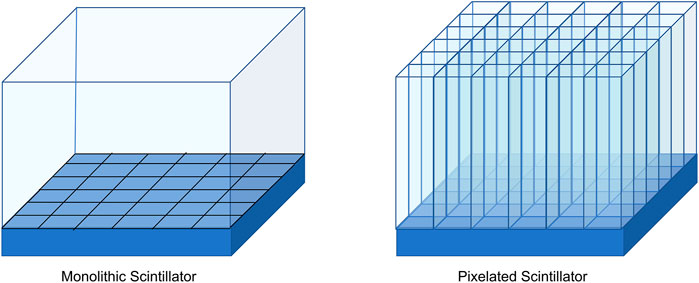
FIGURE 6. Monolithic scintillators are a continuous slab of scintillator material. The photosensor array on the bottom is segmented (Left). Pixelated scintillators are scintillator crystals cut to much smaller dimensions, then combined in a grid to make a complete detector. The photosensors in this figure are 1-to-1 coupled with the pixelated scintillators (Right).
Monolithic scintillators are large crystals that are coupled to photosensors. DOI is available to monolithic scintillators by using the light distribution of the scintillation photons on the photosensors, no additional equipment is required. To use monolithic scintillators, algorithms and calibration procedures need to be developed [117, 118]. The spatial resolution of a monolithic scintillator is dependent on the crystal thickness, and for clinical uses the scintillators need to be 15–30 mm long to maintain sensitivity. It has been shown that high spatial resolution for thick monolithic scintillators is possible. The spatial resolutions ranged from 1.1 mm resolutions for 10 mm long scintillator crystals to 1.7 mm for 22 mm long scintillator crystals while maintaining TOF level timing resolution of 214 ps [119, 120]. Neural networks have also been implemented using monolithic scintillators to reduce the spatial resolution to 1.02 mm for a 16 mm long scintillator [116].
Laser induced optical barriers (LIOB) have also been introduced to monolithic scintillators with the goal of improving spatial resolution. These LIOBs modify the light distribution within the scintillator so that thick monolithic scintillators can be used without excessive light spread. Grids are etched into the crystal using a high-powered laser which modifies the crystal refractive index permanently and helps guide the scintillation light to the photosensors in thick crystals. An example of these LIOBs can be seen in Figure 7. Panetta et al were able to show a spatial resolution of 3 mm for a 25 mm long LYSO crystal with LIOBs in a fine grid pattern [121].
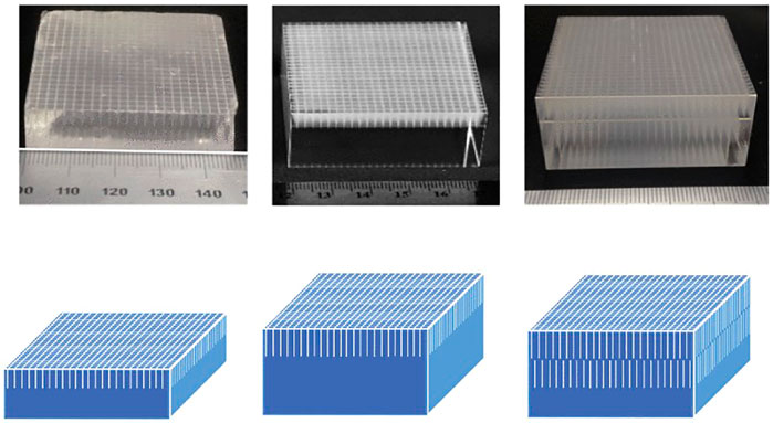
FIGURE 7. Example of single and double set LIOBs on LYSO scintillators of various thicknesses on 50 mm2 cross-section crystals. Top images are etched crystals, bottom images are schematics of the LIOB, etch patterns. A scintillator 14 mm thick with a single layer of LIOB 5 mm long (Left). A scintillator 25 mm thick with a single layer of LIOB 8 mm long (Center). A scintillator 25 mm thick with a double layer of LIOB 8 mm long (Right). The LIOBs act as a light guide in the monolithic scintillators improving spatial resolution. Ⓒ[2018] IEEE. Reprinted, with permission, from [121].
5.3 Novel detector configurations
A common method for improving the sensitivity of the PET scanner is to use longer scintillator crystals to capture more high-energy photons. However, this increases the parallax error which degrades the spatial resolution. In addition, to improve the spatial resolution, scintillators with smaller area (pixel size) are commonly used, but the long aspect ratio reduces the light collection efficiency and worsens energy and timing resolution. To maintain a high level of sensitivity, energy resolution, timing resolution, and spatial resolution, novel detector configurations must be designed.
One proposed solution was to utilize LYSO scintillators in a layered structure with side readouts using SiPMs. The layered structure was made up of four 13.34 × 13.34 × 2.76 mm3 scintillators of LYSO with enhanced specular reflector films between each crystal. A stack of four layers was used in these studies, but the system is easily scalable [122–124]. Four 4 × 4 arrays of SiPMs were connected to each side face of the layered scintillator. Figure 8A shows an illustration of this set-up and Figure 8B shows the actual set up from the top with LYSO scintillator and SensL SiPM arrays coupled to the side faces. This configuration has built in depth-encoding, and the DOI resolution of this configuration is 3.3 mm whichimproves spatial resolution [124]. Another possible improvement to the image quality is using Compton scattering for reconstruction. Typically, Compton scattering events are rejected for reconstruction, but if these events could be recovered, the SNR and sensitivity would be increased, and image quality would be improved [74]. A possible caveat of utilizing Compton scattering is the need for additional processing algorithms [125, 126]. A Compton scattering event can be identified because it will cause energy to be collected in more than one layer of the stack. The first interaction location could then be estimated [123]. Using this configuration, the energy resolution was found to be 10.3% while also having a timing resolution of 348 ps The spatial resolution was found to be 1.1 mm, which shows a proof of concept for high spatial resolution while maintaining or improving energy and timing resolutions [122, 123].
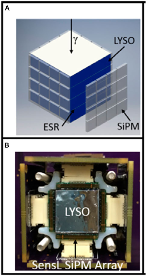
FIGURE 8. (A) Drawing of 13.34 × 13.34 × 2.76 mm3 LYSO scintillators layered in a stack of four with side readouts using four 4 × 4 arrays of SiPMs on each side face of the scintillators. The scintillators are separated by enhanced specular reflector (ESR) films between each crystal. (B) Image of the system from the top with SensL SiPM arrays coupled to the side of the LYSO scintillator. Reproduced with permission from [122] ⒸInstitute of Physics and Engineering in Medicine. Reproduced by permission of IOP Publishing Ltd. All rights reserved.
Utilizing DOI in PET can achieve high spatial resolution by reducing the parallax error. Prism-PET system is a depth-encoded TOF-PET system that uses an array of LYSO scintillators coupled to a prismatoid light guide. Opposite the light guide a pixelated readout array of SiPMs is coupled to the scintillator array. The prismatoid light guide works to confine light sharing to scintillators sharing the same prismatoid. This maximizes the signal-to-background of the SiPMs, improves energy resolution, and DOI information. A 16 × 16 array of 0.96 × 0.96 × 20 mm3 LYSO scintillators were coupled in a 9-to-1 ratio with an 8 × 8 SiPM array. The prismatoid light guide, scintillators, and SiPMs were aligned so each scintillator was coupled to other scintillators connected to different SiPMs. When compared to the DOI resolution of 5 mm FWHM for PET detector with a uniform light guide, the DOI resolution for Prism-PET was improved to 2.5 mm FWHM which was one the best DOI localization reported for single-ended readout detectors [127].
5.4 Collimator design
Spatial resolution in SPECT is typically limited by the collimator design. Collimators in SPECT are a plate of dense material, usually lead, with several holes in the plate. For parallel collimators, these holes only allow photons that are perpendicular to the hole opening through to the SPECT detector. The dense material acts as a blocking layer for a large number of the high-energy photons. Parallel collimators are the standard collimator used in clinical practice. System resolution is defined by Eqs 9, 10, 11:
where Ri is the intrinsic resolution of the detector, Rpaho the resolution of the parallel hole collimator, h is the distance from the source, d is the hole diameter, t is the septal thickness, a is the collimator thickness, aeff is the adjusted thickness caused by penetration of the photon, and µ is the attenuation coefficient depending on the collimator material and radio-tracer [128]. Parallel hole collimators tend to leave a lot of the detector unused which will reduce the spatial resolution of the system. To improve the spatial resolution, the holes in the collimator can be tilted toward a focal point; this is called a fan beam collimator. This allows for more photons to go through the collimator, and also magnifies the object on the detector. The system resolution for a fan beam collimator is shown in Eqs 12, 13, 14:
where mconv(h) is the collimator magnification, f is the focal length, Rconv (h, θ) is the geometric resolution, θis the angle between the detected gamma ray and normal to the detector, a is the collimator thickness, aeff is the adjusted thickness caused by penetration of the photon, and h is the distance from the source. The intrinsic spatial resolution of the detector is essentially improved by the magnification of mconv [128]. These collimators are useful for brain imaging because the scanned area is smaller than the detector [129, 130].
Pin-hole collimators are also a way to improve the spatial resolution of SPECT. The spatial resolution of these collimators is directly related to the size of the pinhole. A smaller pinhole will result in a better spatial resolution. These collimators can achieve sub-millimeter spatial resolutions and have been implemented in many SPECT systems for small animal imaging. Unfortunately, the sensitivity of the SPECT system is negatively affected by these pin-hole collimators, since the number of photons allowed through the pin-hole is significantly decreased. Multiple pin-hole collimators have been a method to increase sensitivity while maintaining high spatial resolution. There is a trade-off between sensitivity and spatial resolution when comparing multiple pin-hole collimators to single pin-hole collimators due to possible overlap of the projections on to the detector when using a multiple pin-hole collimator. This degradation is worsened with increasing pin-hole size [130].
A recent study used multiple pinhole collimators with 75 pinholes with 0.25, 0.60, and 1.00 mm sized pinholes for improved spatial resolution. The ultra-high sensitivity system with a single 0.25 mm pinhole was capable of distinguishing 0.35 mm rods. The general purpose system with 75 pinholes sized 0.60 mm had a spatial resolution of 0.50 mm [131].
Collimator pinhole shape will also play a pivotal role in the spatial resolution and sensitivity of a SPECT system. A comparison study of hexagonal, square, and round hole collimators measured at 2.5 cm from the collimator surface has shown simulated spatial resolutions of 2.68, 2.96, and 3.06 mm, respectively [132].
6 Emerging technologies
While PET and SPECT have been integrated into clinical work and have found success for various imaging needs, there is always a need for innovation and the development of new technologies and techniques. The above discussion was focused on continuing the improvement of the systems that are already in use in industry, but there are some areas where there are novel uses for PET and SPECT that should be addressed for the future.
6.1 Novel collimators for SPECT
Organ specific SPECT is an increasingly growing area. Typical organ specific SPECT systems use pinhole collimators for improvement to spatial resolution. The system sensitivity, S, is directly proportional to the pinhole size given by Eq. 15:
where D is the pinhole diameter and do is the distance from the object to the pinhole plane [133]. The resolution of related to the pinhole is dependent on the pinhole dimension shown by Eq. 16:
where di is the distance between the pinhole and the image [133]. The sensitivity and resolution are inversely tied together. An increase in sensitivity will result in a larger, less desirable resolution [134]. Another challenge for these collimators is the acceptance angle is not adjustable for different regions of interest due to fixed pinhole shape and size. The magnifying factor of a SPECT system is proportional to the distance between the pinhole and the detector and the diameter FOV. Minimizing the FOV will result in a high resolution, but typical collimators have a fixed FOV. A novel solution to this issue has been proposed by creating a variable pinhole collimator with flexible parameters. This collimator is constructed by stacking tungsten plates with different sized apertures and the detector and collimator are set up on actuators to move the collimator as close to the subject as possible for maximum sensitivity. The actuators then adjust the distance from the pinhole from the scintillator and the acceptance angle. This optimizes both the system sensitivity and spatial resolution. Rods of 0.6 mm were able to be distinguished using this adjustable system while 1.2 mm rods were barely discernible for the fixed pinhole collimator [135].
By changing the geometry of the aperture of the collimator, the resolution of SPECT can be increased, so it is advantageous to have a system that allows for changes to the collimator. Typically, collimator design and fabrication is a difficult and costly process using traditional mechanical techniques. To improve the fabrication and cost of the collimator, novel manufacturing techniques are being explored: 3-D printing, cold casting, and investment casting. 3-D printing is an additive manufacturing method which uses resin that can be used to create custom molds for collimators. After these molds are printed, either cold casting or investment casting can be used to fabricate the collimators out of a tungsten composite or platinum. These techniques can be used to create novel apertures with lower cost and faster turnaround time compared to traditional machining methods [136].
6.2 Multi-tracer PET
Different radio-tracers can be used to characterize tumors more effectively, but unlike SPECT, PET systems measure coincident photons that always measure 511 keV. Due to this lack of energy difference in the measured photons, PET typically relies on one radio-tracer at a time, and sometimes multiple PET scans must be run on the patient over the course of a few hours or sometimes days. Multi-tracer PET is a method of PET that uses different radio-tracers during one scan to give insight into different processes within the tumor. There is a need to be able to separate out the signals between the radio-tracers, and this cannot be done via energy resolution. There are a few ways researchers have found to differentiate the signals: different radio-active half-life, compartment modeling, staggered dose injections, and prompt gamma [137–139]. Using this method can give more insight into tumor physiology, and in the future could help oncology research.
6.3 Compton imaging and PET
PET and SPECT are complimentary nuclear medicine imaging modalities where PET has shown great sensitivity when compared to SPECT, but SPECT radio-tracers are helpful in diagnosis and treatment since these tracers can be tumor-specific. Unfortunately, it is difficult to combine SPECT and PET modalities due to the collimator in the SPECT design. A proposed solution is to use Compton imaging with PET. Coincidence detection of the annihilation photons is still used for imaging, but additionally, SPECT nuclides are detected using Compton imaging [140]. Compton cameras have recently transitioned from astrophysical applications to medical imaging [141]. Figure 9 is a schematic of the Compton-PET hybrid camera for PET and SPECT tracer imaging. Absorbers, such as scintillator or semiconductor detectors, surround the subject similar to PET. Additionally, there are scatterers that surround the subject inside the absorber ring. PET imaging is similar in this camera as typical PET systems, Compton imaging works by detecting coincident between a scattered gamma ray and an absorbed gamma ray. Using this information, the location of the source can be found within the conical surface shown in Figure 9 as the dashed black line and the blue oval [140, 141].
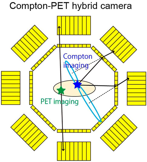
FIGURE 9. Compton-PET Hybrid camera. Both PET and SPECT tracers can be imaged with this camera. The thick yellow boxes represent absorbers. The thin yellow boxes represent scatterers. Coincident detection of annihilation photons (green star and black arrows) is done via the absorbers, similar to traditional PET systems. SPECT tracers (blue star) are visualized by using coincident detection of a scattered gamma ray in a scatterer, and an absorbed gamma ray in an absorber. The solid black arrows represent gamma rays scattering in different scatterers, then being absorbed by different absorbers. Dashed lines are the axes of the Compton cones. Blue ovals are the base of the Compton cones. Reproduced under CC-BY license 4.0 from [140].
A study was completed using high resolution GAGG 2.5 × 2.5 × 9 mm3 scintillators in an 8 × 8 array coupled to an 8 × 8 array of SiPMs for the absorbers. The scattering layers were high resolution GAGG 2.5 × 2.5 × 1.5 mm3 in an 8 × 8 array also coupled to an 8 × 8 array of SiPMs. The Compton imaging for this study is optimized for 150 keV–400 keV. The energy resolution of the scatterers at 59.54 keV was 18.2% FWHM. Above 100 keV the energy resolution improved to 11%–15% FWHM. Spatial resolution for PET imaging was 3.3 mm FWHM for both horizontal and vertical axes. The Compton imaging at 511 keV was 4.2 mm FWHM for the horizontal axis and 3.8 mm FWHM for the vertical axis [140].
Another group has completed similar work using scatterer and absorber rings for PET and Compton imaging. The PET detector is made of 2.8 × 2.8 × 7.5 mm3 Zr-doped gadolinium oxyorthosilicate (GSOZ) scintillators coupled to PMTs. The scatterer ring was made of 0.9 × 0.9 × 6.0 mm3 GAGG scintillators coupled with a multi-pixel photon counter array. The energy resolution at 511 keV for the scatterer and absorber were 17% and 14%, respectively [142].
Another method uses β+-gamma coincidences in a PET system called gamma-PET where an additional gamma photon is emitted with the positron for PET. There are many radio-tracers which are possible for gamma-PET with Scandium-44 being the most utilized [143, 144]. True events can be separated from the random events by measuring the event in three dimensions. The position of the radio-tracer is found to be the intersection of the LOR for the annihilation photon and the gamma ray cone. An advantage of this system is the reduction of image blurring caused by the positron range. Simulations showed a spatial resolution of 0.4 mm in a small animal system [143–146].
6.4 Quantum entanglement and PET
It is well understood that random coincidences and scatter events degrade the PET image. To reduce the effect of these events, better correlation between the annihilation photons needs to be made so that only true events are used for image reconstruction. When the annihilation photons are generated, there is a common entangled wave function that connects these two photons even after separation. This quantum entanglement presents as the annihilation photons being linearly polarized so the vectors are orthogonal to each other. By using this quantum entanglement, the true events can be identified by measuring their polarization [147, 148].
Compton PET systems, mentioned above, are possible candidates for quantum entanglement in PET. The Compton cameras have shown capabilities of sorting coincidences based on the polarization correlation of the annihilation photons in simulation [149]. Polarization correlation degrades with each scattering, so it is important to optimize the system for single Compton interaction of 511 keV. A simulation study of a Compton-PET system found a 22% image quality improvement to SNR ratio when discriminating scattered coincidence events based on their angular correlation [150].
6.5 Total body PET
As mentioned previously, sensitivity is an important defining factor for PET imaging. Typical PET systems surround the desired area with detectors but do not have complete coverage of the entire subject. These systems have poor sensitivity of less than 1% due to two primary factors: most of the subject is outside the FOV of the scanner so no signal is collected from these body parts and only 3%–5% of the available signal from body parts within the scanner is collected due to the isotopically emitted radiation not being incident on the detectors [151]. The top section of Figure 10 shows an example of a typical PET system where the subject is moved through the system to reconstruct a total body scan. A recent breakthrough in the sensitivity of PET systems is the introduction of total body scanners. These systems comprise of a ring of detectors surrounding the subject, similar to a typical system, but they have an increased axial length so that the entire subject lies within the rings. The bottom section of Figure 10 shows an example of a total body PET system with a long axial FOV. The entire body scan can be reconstructed using a single scan instead of many which results in a decrease in acquisition time. An increase in axial FOV to cover the entire body increases the sensitivity by a factor of 40 for total body scanning [151, 153] and when looking at single organs the increase in sensitivity is increased by a factor of 3–4 [152]. These scanners have an axial FOV from 1 to 2 m which increases the signal collection efficiency and sensitivity [154–157].
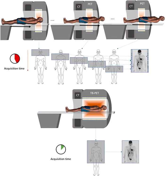
FIGURE 10. Top: Typical PET system with multiple scans to reconstruct a whole body image. Bottom: Total body PET system with a single scan to reconstruct a whole body image. Reproduced under CC-BY license 4.0 from [152].
There are three primary groups working on total body PET systems: United uExplorer at the University of California-Davis, PennPET Explorer at the University of Pennsylvania, and the Siemens Biograph Vision Quadra. The uExplorer and Biograph Vision Quadra have been used in clinical studies while the PennPET Explorer is used mostly for research studies [151, 155, 156, 158, 159]. Table 3 summarizes the characteristics of these three systems. All three systems use pixelated Lu-based scintillators, either LYSO or LSO, with SiPMs, but the scintillator to SiPM coupling is slightly different with the uExplorer having 10.5 scintillators per SiPM, the PennPET Explorer has one scintillator per SiPM, and the Biograph Vision Quadra has five scintillators per SiPM. Each has a similar ring diameter ranging from 76.4 cm for the PennPET Explorer to 78.6 cm for the uExplorer. The uExplorer has the longest axial FOV at 194 cm whereas the PennPET Explorer has an axial FOV 142 cm, and the Biograph Vision Quadra has an axial FOV of 106 cm [151, 155, 156, 158]. These systems have a wide range of proposed applications. The detection of cancer and other systemic conditions is a focal point of work with total body PET. Total body PET will offer the ability to image all the organs in a body in a single scan, which could help with diagnosis and research of multi-organ diseases, such as Parkinson disease. Total body PET can also aid in the development and study of drugs [151]. With the increased sensitivity of total body PET, the dose of the radiotracer could be reduced for ultra-low dose PET scans which could be beneficial for cancer screening or testing on different subjects, such as pediatric or maternal patients [160].
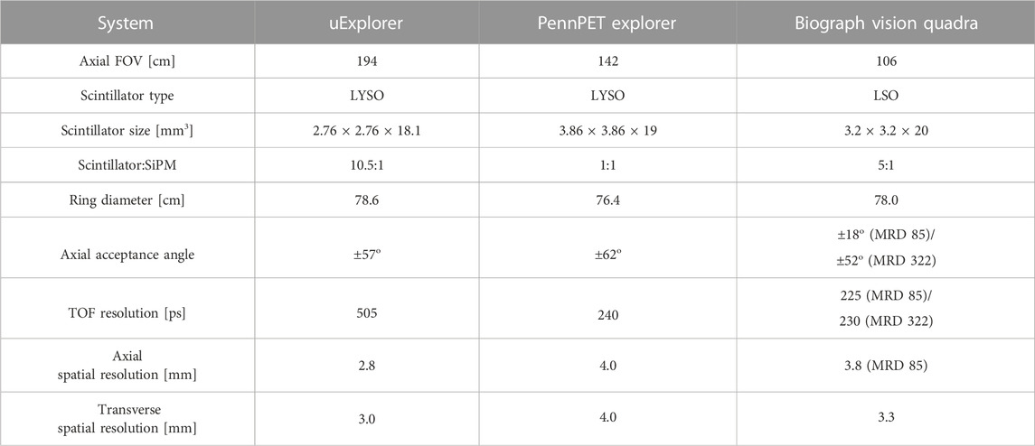
TABLE 3. Summary of total body PET systems. The Biograph Vision Quadra reconstructions can be performed at a maximum ring distance of 322 crystals (MRD 322) or 85 crystals (MRD 85) [152, 155, 156].
7 Conclusion
While PET and SPECT are already established clinical modalities, there is still room for improvement to both systems. For PET, improving the sensitivity and timing resolution have been major driving factors of recent research. Total-body PET systems have shown dramatic improvements to the sensitivity. Novel detector designs utilizing both new materials and creative readouts have pushed TOF-PET systems to the forefront of clinical imaging and research. Improvements to spatial resolution are also being explored through depth-encoded detectors to give more accurate location information. Multi-tracer PET will allow for better understanding of tumors, while using the quantum entanglement of annihilation photons could improve scatter and random event rejection, thus improving image quality.
For SPECT, improving collimator design has been shown to improve the spatial resolution. Detector material selection for improved energy resolution is also a driving factor of SPECT research where semiconductor detectors have found implementation in high quality SPECT systems due to their desirable energy resolutions. By continuing work on detector development, it is possible that the physical limits of PET and SPECT can be reached, leading to the highest quality images for each application while minimizing the time and dose for each scan.
Author contributions
Conceptualization, EE and SA; image generation, EE; writing—original draft preparation, EE; writing—review and editing, EE, SA; supervision, SA. All authors have read and agreed to the published version of the manuscript.
Conflict of interest
The authors declare that the research was conducted in the absence of any commercial or financial relationships that could be construed as a potential conflict of interest.
Publisher’s note
All claims expressed in this article are solely those of the authors and do not necessarily represent those of their affiliated organizations, or those of the publisher, the editors and the reviewers. Any product that may be evaluated in this article, or claim that may be made by its manufacturer, is not guaranteed or endorsed by the publisher.
References
1. Hutton BF, Goorden MC, Beekman FJ. SPECT and SPECT/CT. Mol Imaging (2021) 2021:29–45. doi:10.1016/B978-0-12-816386-3.00008-9
2. Ferrari M, De Marco P, Origgi D, Pedroli G. SPECT/CT radiation dosimetry. Clin Translational Imaging (2014) 2:557–69. doi:10.1007/s40336-014-0093-8
3. Tafti BA, Padia SA. Dosimetry of Y-90 microspheres utilizing Tc-99m SPECT and Y-90 PET. Semin Nucl Med (2019) 49:211–7. doi:10.1053/j.semnuclmed.2019.01.005
4. Schaart DR. Physics and technology of time-of-flight PET detectors. Phys Med Biol (2021) 66:09TR01. doi:10.1088/1361-6560/abee56
5. Ritt P. Recent developments in SPECT/CT. Semin Nucl Med (2022) 52:276–85. doi:10.1053/j.semnuclmed.2022.01.004
6. Wyngaert TV, Elvas F, Schepper SD, Kennedy JA, Israel O. SPECT/CT: Standing on the shoulders of giants, it is time to reach for the sky. J Nucl Med (2020) 61:1284–91. doi:10.2967/jnumed.119.236943
8. Kijewski MF. Chapter 33 - positron emission tomography and single-photon emission computed tomography physics. In: HB Newton editor. Handbook of neuro-oncology neuroimaging. 3rd ed. United States: Academic Press (2022). p. 415–21. doi:10.1016/B978-0-12-822835-7.00061-5
9. Surti S, Karp JS. Update on latest advances in time-of-flight PET. Physica Med (2020) 80:251–8. doi:10.1016/j.ejmp.2020.10.031
10. Berg E, Cherry SR. Innovations in instrumentation for positron emission tomography. Semin Nucl Med (2018) 48:311–31. doi:10.1053/j.semnuclmed.2018.02.006
11. Muehllehner G, Karp JS. Positron emission tomography. Phys Med Biol (2006) 51:R117–37. doi:10.1088/0031-9155/51/13/R08
12. Nakanishi K, Hirano Y, Yamamoto S. Comparison of noise equivalent count rates (NECRs) for the PET systems with different ring diameter and electronics. IEEE Trans Radiat Plasma Med Sci (2018) 3:371–6. doi:10.1109/trpms.2018.2876410
13. Adler SS, Seidel J, Choyke PL. Advances in preclinical PET. Semin Nucl Med (2022) 52:382–402. doi:10.1053/j.semnuclmed.2022.02.002
14. Miyaoka RS, Lehnert AL. Small animal PET: A review of what we have done and where we are going. Phys Med Biol (2020) 65:24TR04. doi:10.1088/1361-6560/ab8f71
15. Meikle SR, Sossi V, Roncali E, Cherry SR, Banati R, Mankoff D, et al. Quantitative PET in the 2020s: A roadmap. Phys Med Biol (2021) 66:06RM01. doi:10.1088/1361-6560/abd4f7
16. Wang Y, Herbst R, Abbaszadeh S. Development and characterization of modular readout design for two-panel head-and-neck dedicated PET system based on CZT detectors. IEEE Trans Radiat Plasma Med Sci (2021) 6:517–21. doi:10.1109/trpms.2021.3111547
17. Surti S, Pantel AR, Karp JS. Total body PET: Why, how, what for? IEEE Trans Radiat plasma Med Sci (2020) 4:283–92. doi:10.1109/trpms.2020.2985403
18. Moses WW. Fundamental limits of spatial resolution in PET. Nucl Instr Methods Phys Res Section A, Acc spectrometers, detectors associated equipment (2011) 648:S236–40. doi:10.1016/j.nima.2010.11.092
19. Gonzalez-Montoro A, Ullah MN, Levin CS. Advances in detector instrumentation for PET. J Nucl Med (2022) 63:1138–44. doi:10.2967/jnumed.121.262509
20. Studen A. Physics of imaging in nuclear medicine. In: A Giussani, and C Hoeschen editors. Imaging in nuclear medicine. Berlin, Heidelberg: Springer (2013). p. 19–41. doi:10.1007/978-3-642-31415-5_3
21. Gundacker S, Turtos RM, Auffray E, Paganoni M, Lecoq P. High-frequency SiPM readout advances measured coincidence time resolution limits in TOF-PET. Phys Med Biol (2019) 64:055012. doi:10.1088/1361-6560/aafd52
22. Kovaltchouk V, Lolos G, Papandreou Z, Wolbaum K. Comparison of a silicon photomultiplier to a traditional vacuum photomultiplier. Nucl Instr Methods Phys Res Section A: Acc Spectrometers, Detectors Associated Equipment (2005) 538:408–15. doi:10.1016/j.nima.2004.08.136
23. Gundacker S, Heering A. The silicon photomultiplier: Fundamentals and applications of a modern solid-state photon detector. Phys Med Biol (2020) 65:17TR01. doi:10.1088/1361-6560/ab7b2d
24. Schaart DR. Introduction to silicon photomultipliers for time-of-flight PET. In: Advances in PET. Berlin, Germany: Springer (2020). p. 27–40.
25. Zatcepin A, Ziegler SI. Detectors in positron emission tomography. Z für Medizinische Physik (2022) 33:4. doi:10.1016/j.zemedi.2022.08.004
26. Hu P, Hua Z, Ma L, Qian S, Wu Q, Wang Z. Study on the optimized energy resolution of scintillator detectors based on SiPMs and LYSO: Ce. J Instrumentation (2022) 17:T09010. doi:10.1088/1748-0221/17/09/t09010
27. Roberts OJ. Lanthanum halide and cerium bromide scintillators. In: Solid-state radiation detectors. United States: CRC Press (2015). p. 261–84.
28. Redus R, Pantazis J, Huber A, Jordanov V, Butler J, Apotovsky B. Fano factor determination for CZT. MRS Online Proc Libr (Opl) (1997) 487:101. doi:10.1557/proc-487-101
30. Bora V, Barrett HH, Fastje D, Clarkson E, Furenlid L, Bousselham A, et al. Estimation of Fano factor in inorganic scintillators. Nucl Instr Methods Phys Res Section A: Acc Spectrometers, Detectors Associated Equipment (2016) 805:72–86. doi:10.1016/j.nima.2015.07.009
31. Moszynski M, Balcerzyk M, Czarnacki W, Kapusta M, Klamra W, Syntfeld A, et al. Intrinsic energy resolution and light yield nonproportionality of BGO. IEEE Trans Nucl Sci (2004) 51:1074–9. doi:10.1109/tns.2004.829491
32. Quarati F, Dorenbos P, Van Der Biezen J, Owens A, Selle M, Parthier L, et al. Scintillation and detection characteristics of high-sensitivity CeBr3 gamma-ray spectrometers. Nucl Instr Methods Phys Res Section A: Acc Spectrometers, Detectors Associated Equipment (2013) 729:596–604. doi:10.1016/j.nima.2013.08.005
33. Yoshino M, Kamada K, Shoji Y, Yamaji A, Kurosawa S, Yokota Y, et al. Effect of Mg co-doping on scintillation properties of Ce: Gd3 (Ga, Al) 5O12 single crystals with various Ga/Al ratios. J Cryst Growth (2017) 468:420–3. doi:10.1016/j.jcrysgro.2016.12.054
34. Hawrami R, Ariesanti E, Buliga V, Burger A. Thallium strontium iodide: A high efficiency scintillator for gamma-ray detection. Opt Mater (2020) 100:109624. doi:10.1016/j.optmat.2019.109624
35. Yu X, Zhang X, Zhang H, Peng H, Ren Q, Xu J, et al. Requirements of scintillation crystals with the development of PET scanners. Crystals (2022) 12:1302. doi:10.3390/cryst12091302
36. Kuhn A, Surti S, Karp J, Raby P, Shah K, Perkins A, et al. Design of a lanthanum bromide detector for time-of-flight PET. IEEE Trans Nucl Sci (2004) 51:2550–7. doi:10.1109/tns.2004.835777
37. Johns PM, Nino JC. Room temperature semiconductor detectors for nuclear security. J Appl Phys (2019) 126:040902. doi:10.1063/1.5091805
38. Alekhin MS, de Haas JTM, Khodyuk IV, Krämer KW, Menge PR, Ouspenski V, et al. Improvement of γ -ray energy resolution of LaBr3:Ce3+ scintillation detectors by Sr2+ and Ca2+ co-doping. Appl Phys Lett (2013) 102:161915. doi:10.1063/1.4803440
39. Schaart DR, Schramm G, Nuyts J, Surti S. Time of flight in perspective: Instrumental and computational aspects of time resolution in positron emission tomography. IEEE Trans Radiat plasma Med Sci (2021) 5:598–618. doi:10.1109/trpms.2021.3084539
40. Moszyński M, Zalipska J, Balcerzyk M, Kapusta M, Mengesha W, Valentine J. Intrinsic energy resolution of NaI (Tl). Nucl Instr Methods Phys Res Section A: Acc Spectrometers, Detectors Associated Equipment (2002) 484:259–69. doi:10.1016/s0168-9002(01)01964-7
41. Moszyński M, Syntfeld-Każuch A, Swiderski L, Grodzicka M, Iwanowska J, Sibczyński P, et al. Energy resolution of scintillation detectors. Nucl Instr Methods Phys Res Section A: Acc Spectrometers, Detectors Associated Equipment (2016) 805:25–35. doi:10.1016/j.nima.2015.07.059
42. Lecoq P. Development of new scintillators for medical applications. Nucl Instr Methods Phys Res Section A: Acc Spectrometers, Detectors Associated Equipment (2016) 809:130–9. doi:10.1016/j.nima.2015.08.041
43. Omidvari N, Cheng L, Leung EK, Abdelhafez YG, Badawi RD, Ma T, et al. Lutetium background radiation in total-body pet—A simulation study on opportunities and challenges in pet attenuation correction. Front Nucl Med (2022) 2:963067. doi:10.3389/fnume.2022.963067
44. Zavartsev YD, Zavertyaev M, Zagumennyi A, Zerrouk A, Kozlov V, Kutovoi S. New radiation resistant scintillator LFS-3 for electromagnetic calorimeters. Bull Lebedev Phys Inst (2013) 40:34–8. doi:10.3103/s1068335613020024
45. Bisogni MG, Attili A, Battistoni G, Belcari N, Camarlinghi N, Cerello P, et al. INSIDE in-beam positron emission tomography system for particle range monitoring in hadrontherapy. J Med Imaging (2017) 4:011005. doi:10.1117/1.jmi.4.1.011005
46. Cates JW, Gu Y, Levin CS. Direct conversion semiconductor detectors in positron emission tomography. Mod Phys Lett A (2015) 30:1530011. doi:10.1142/s0217732315300116
47. Abbaspour S, Mahmoudian B, Islamian J. Cadmium telluride semiconductor detector for improved spatial and energy resolution radioisotopic imaging. World J Nucl Med (2017) 16:101–7. doi:10.4103/1450-1147.203079
49. Jin Y, Streicher M, Yang H, Brown S, He Z, Meng LJ. Experimental evaluation of a 3-D CZT imaging spectrometer for potential use in Compton-Enhanced PET imaging. IEEE Trans Radiat Plasma Med Sci (2022) 7:18–32. doi:10.1109/trpms.2022.3200010
50. Hitomi K, Murayama T, Shoji T, Suehiro T, Hiratate Y. Improved spectrometric characteristics of thallium bromide nuclear radiation detectors. Nucl Instr Methods Phys Res Section A: Acc Spectrometers, Detectors Associated Equipment (1999) 428:372–8. doi:10.1016/s0168-9002(99)00141-2
51. Dmitriev Y, Kim H, Higgins W, Cirignano L, Dokhale P, Wong P, et al. Recent progress in tlbr radiation detectors. In: 2006 IEEE Nuclear Science Symposium Conference Record (IEEE); October - 4 November 2006; San Diego, California (2006). p. 3708–10.
52. Ariño-Estrada G, Du J, Kim H, Cirignano LJ, Shah KS, Cherry SR, et al. Development of TlBr detectors for PET imaging. Phys Med Biol (2018) 63:13NT04. doi:10.1088/1361-6560/aac27e
53. He Y, Petryk M, Liu Z, Chica DG, Hadar I, Leak C, et al. Cspbbr3 perovskite detectors with 1.4% energy resolution for high-energy γ-rays. Nat Photon (2021) 15:36–42. doi:10.1038/s41566-020-00727-1
54. He Y, Matei L, Jung HJ, McCall KM, Chen M, Stoumpos CC, et al. High spectral resolution of gamma-rays at room temperature by perovskite CsPbBr3 single crystals. Nat Commun (2018) 9:1609–8. doi:10.1038/s41467-018-04073-3
55. Chaudhuri SK, Sajjad M, Kleppinger JW, Mandal KC. Charge transport properties in CdZnTeSe semiconductor room-temperature γ-ray detectors. J Appl Phys (2020) 127:245706. doi:10.1063/5.0006227
56. Zhu Y, He Z. Performance of larger-volume 40× 40× 10-and 40× 40× 15-mm3 CdZnTe detectors. IEEE Trans Nucl Sci (2021) 68:250–5. doi:10.1109/tns.2021.3052133
57. Iniewski K, Hansson C. High-Z materials for X-ray detection: Material properties and characterization techniques. Berlin, Germany: Springer (2023). p. 1–21.
58. Roy UN, Camarda GS, Cui Y, James RB. Advances in CdZnTeSe for radiation detector applications. Radiation (2021) 1:123–30. doi:10.3390/radiation1020011
59. Roy UN, Camarda G, Cui Y, Gul R, Hossain A, Yang G, et al. Role of selenium addition to CdZnTe matrix for room-temperature radiation detector applications. Scientific Rep (2019) 9:1620–7. doi:10.1038/s41598-018-38188-w
60. Nag R. Growth, characterization and evaluation of CdZnTeSe single crystals for room temperature radiation detectors. Columbia: University of South Carolina (2022). Ph.D. thesis.
61. Chaudhuri SK, Kleppinger JW, Karadavut O, Nag R, Mandal KC. Quaternary semiconductor Cd1-xZnxTe1-ySey for high-resolution, room-temperature gamma-ray detection. Crystals (2021) 11:827. doi:10.3390/cryst11070827
62. Roy UN, Camarda GS, Cui Y, James RB. High-resolution virtual Frisch grid gamma-ray detectors based on as-grown CdZnTeSe with reduced defects. Appl Phys Lett (2019) 114:232107. doi:10.1063/1.5109119
63. Kim H, Ogorodnik Y, Kargar A, Cirignano L, Thrall CL, Koehler W, et al. Thallium bromide gamma-ray spectrometers and pixel arrays. Front Phys (2020) 8:55. doi:10.3389/fphy.2020.00055
64. Lecoq P, Morel C, Prior JO, Visvikis D, Gundacker S, Auffray E, et al. Roadmap toward the 10 ps time-of-flight PET challenge. Phys Med Biol (2020) 65:21RM01. doi:10.1088/1361-6560/ab9500
65. Kwon SI, Ota R, Berg E, Hashimoto F, Nakajima K, Ogawa I, et al. Ultrafast timing enables reconstruction-free positron emission imaging. Nat Photon (2021) 15:914–8. doi:10.1038/s41566-021-00871-2
66. Cates JW, Levin CS. Evaluation of a clinical TOF-PET detector design that achieves ≤ 100 ps coincidence time resolution. Phys Med Biol (2018) 63:115011. doi:10.1088/1361-6560/aac504
67. Kang HG, Yamaya T, Han YB, Song SH, Ko GB, Lee JS, et al. Crystal surface and reflector optimization for the SiPM-based dual-ended readout TOF-DOI PET detector. Biomed Phys Eng Express (2020) 6:065028. doi:10.1088/2057-1976/abc45a
68. Walrand S, Hesse M, Jamar F. Achieving sub-100 ps time-of-flight resolution in thick LSO positron emission tomography while reducing system cost: A Monte Carlo study. Phys Med Biol (2020) 65:205009. doi:10.1088/1361-6560/abb02a
69. Park H, Yi M, Lee JS. Silicon photomultiplier signal readout and multiplexing techniques for positron emission tomography: A review. Biomed Eng Lett (2022) 12:263–83. doi:10.1007/s13534-022-00234-y
70. Xu J, Sun Q, Wu Z, Guo L, Xie S, Huang Q, et al. Development of broad-band high-reflectivity multilayer film for positron emission tomography system. J Instrumentation (2018) 13:P09016. doi:10.1088/1748-0221/13/09/p09016
71. Xie S, Sun Q, Ying G, Guo L, Huang Q, Peng Q, et al. Ultra-precise surface processing of LYSO scintillator crystals for Positron Emission Tomography. Appl Surf Sci (2019) 469:573–81. doi:10.1016/j.apsusc.2018.11.024
72. Tai YC, Goertzen AL, et al. Use of systematic surface roughing to enhance the spatial resolution of the dual-ended readout of axially-oriented 100 mm long LYSO crystals. Phys Med Biol (2012) 57:N501–12. doi:10.1088/0031-9155/57/24/n501
73. Pawlik-Niedźwiecka M, Niedźwiecki S, Alfs D, Białas P, Curceanu C, Czerwiński E, et al. Preliminary studies of J-PET detector spatial resolution. Acta Physica Pol A (2017) 132:1645–9. doi:10.12693/aphyspola.132.1645
74. Baran J, Krzemien W, Raczyński L, Bała M, Coussat A, Parzych S, et al. Realistic total-body J-PET geometry optimization–Monte Carlo study. arXiv preprint arXiv:2212.02285 (2022).
75. Dadgar M, Parzych S, Ardebili FT, Baran J, Chug N, Curceanu C, et al. Investigation of novel preclinical total body PET designed with J-PET technology: A simulation study. IEEE Trans Radiat Plasma Med Sci (2022) 7:124. doi:10.1109/TRPMS.2022.3211780
76. Ariño-Estrada G, Mitchell GS, Kim H, Du J, Kwon SI, Cirignano LJ, et al. First Cerenkov charge-induction (CCI) TlBr detector for TOF-PET and proton range verification. Phys Med Biol (2019) 64:175001. doi:10.1088/1361-6560/ab35c4
77. Gonzalez-Montoro A, Pourashraf S, Cates JW, Merzi S, Gola A, Borghi G, et al. Physical considerations for Cherenkov radiation based coincidence time resolution measurements in BGO. In: 2021 IEEE Nuclear Science Symposium and Medical Imaging Conference (NSS/MIC) (IEEE); 16-23 October 2021; Piscataway, NJ, USA (2021). p. 1–3.
78. Gonzalez-Montoro A, Pourashraf S, Cates JW, Levin CS. Cherenkov radiation–based coincidence time resolution measurements in BGO scintillators. Front Phys (2022) 10:13. doi:10.3389/fphy.2022.816384
79. Kratochwil N, Gundacker S, Auffray E. A roadmap for sole Cherenkov radiators with SiPMs in TOF-PET. Phys Med Biol (2021) 66:195001. doi:10.1088/1361-6560/ac212a
80. Kratochwil N, Gundacker S, Lecoq P, Auffray E. Pushing Cherenkov PET with BGO via coincidence time resolution classification and correction. Phys Med Biol (2020) 65:115004. doi:10.1088/1361-6560/ab87f9
81. Terragni G, Pizzichemi M, Roncali E, Cherry SR, Glodo J, Shah K, et al. Time resolution studies of Thallium based Cherenkov semiconductors. Front Phys (2022) 10:93. doi:10.3389/fphy.2022.785627
82. Ariño-Estrada G, Mitchell GS, Kwon SI, Du J, Kim H, Cirignano LJ, et al. Towards time-of-flight PET with a semiconductor detector. Phys Med Biol (2018) 63:04LT01. doi:10.1088/1361-6560/aaaa4e
83. Tamura R, Pratt EC, Grimm J. Innovations in nuclear imaging instrumentation: Cerenkov imaging. Semin Nucl Med (2018) 48:359–66. doi:10.1053/j.semnuclmed.2018.02.007
84. Gonzalez-Montoro A, Sanchez F, Majewski S, Zanettini S, Benlloch J, Gonzalez A. Highly improved operation of monolithic BGO-PET blocks. J Instrumentation (2017) 12:C11027. doi:10.1088/1748-0221/12/11/c11027
85. Ariño-Estrada G, Roncali E, Selfridge AR, Du J, Glodo J, Shah KS, et al. Study of cerenkov light emission in the semiconductors TlBr and TlCl for TOF-PET. IEEE Trans Radiat Plasma Med Sci (2020) 5:630–7. doi:10.1109/trpms.2020.3024032
86. Konstantinou G, Barrio J, Moliner L, Cañizares G, Cucarella N, Benlloch JM, et al. A novel metascintillator approach for ultra-fast timing in positron emission tomography. In: 2020 IEEE Nuclear Science Symposium and Medical Imaging Conference (NSS/MIC) (IEEE); 31 October - 7 November 2020; Boston, United States (2020). p. 1–4.
87. Lecoq P, Konstantinou G, Latella R, Moliner L, Nuyts J, Zhang L, et al. Metascintillators: New results for TOF-PET applications. IEEE Trans Radiat Plasma Med Sci (2022) 6:510–6. doi:10.1109/trpms.2022.3161473
88. Moliner L, Konstantinou G, Benlloch JM, Lecoq P. Towards TOF improvements: Metascintillator simulation using BaF 2 as fast scintillator. In: 2021 IEEE Nuclear Science Symposium and Medical Imaging Conference (NSS/MIC) (IEEE); 16-23 October 2021; Yokohama,; Japan (2021). p. 1–4.
89. Agodi C, Alba R, Bellia G, Coniglione R, Del Zoppo A, Maiolino C, et al. BaF2 scintillator: A stand-alone detector for γ-rays and light charged particles. Nucl Instr Methods Phys Res Section A: Acc Spectrometers, Detectors Associated Equipment (1988) 269:595–8. doi:10.1016/0168-9002(88)90138-6
90. Konstantinou G, Lecoq P, Benlloch JM, Gonzalez AJ. Metascintillators for ultrafast gamma detectors: A review of current state and future perspectives. IEEE Trans Radiat Plasma Med Sci (2021) 6:5–15. doi:10.1109/trpms.2021.3069624
91. Moskal P, Stepień E. Prospects and clinical perspectives of total-body PET imaging using plastic scintillators. PET Clinics (2020) 15:439–52. doi:10.1016/j.cpet.2020.06.009
92. Moskal P, Niedźwiecki S, Bednarski T, Czerwiński E, Kubicz E, Moskal I, et al. Test of a single module of the J-PET scanner based on plastic scintillators. Nucl Instr Methods Phys Res Section A: Acc Spectrometers, Detectors Associated Equipment (2014) 764:317–21. doi:10.1016/j.nima.2014.07.052
93. Niedźwiecki S, Białas P, Curceanu C, Czerwiński E, Dulski K, Gajos A, et al. J-PET: A new technology for the whole-body PET imaging. Acta Physica Pol B (2017) 48:1567. doi:10.5506/aphyspolb.48.1567
94. Moskal P, Rundel O, Alfs D, Bednarski T, Białas P, Czerwiński E, et al. Time resolution of the plastic scintillator strips with matrix photomultiplier readout for J-PET tomograph. Phys Med Biol (2016) 61:2025–47. doi:10.1088/0031-9155/61/5/2025
95. Wang Y, Abbaszadeh S. Optical properties modulation: A new direction for the fast detection of ionizing radiation in PET. In: Advanced X-ray radiation detection: Medical imaging and industrial applications. Berlin, Germany: Springer (2022). p. 149–64.
96. Wang Y, Li Y, Yi F, Li J, Xie S, Peng Q, et al. Two-crossed-polarizers based optical property modulation method for ionizing radiation detection for positron emission tomography. Phys Med Biol (2019) 64:135017. doi:10.1088/1361-6560/ab23cb
97. Wang Y, Tao L, Abbaszadeh S, Levin C. Further investigations of a radiation detector based on ionization-induced modulation of optical polarization. Phys Med Biol (2021) 66:055013. doi:10.1088/1361-6560/abe027
98. Wang Y, Tao L, Levin CS, Xu J. Approaches to improving the detection sensitivity of optical modulation based radiation detection method for positron emission tomography. In: 2019 IEEE Nuclear Science Symposium and Medical Imaging Conference (NSS/MIC) (IEEE); 26 October-2 November 2019; Manchester,; United Kingdom (2019). p. 1–3.
99. Tao L, Coffee RN, Jeong D, Levin CS. Ionizing photon interactions modulate the optical properties of crystals with femtosecond scale temporal resolution. Phys Med Biol (2021) 66:045032. doi:10.1088/1361-6560/abd951
100. Berg E, Cherry SR. Using convolutional neural networks to estimate time-of-flight from PET detector waveforms. Phys Med Biol (2018) 63:02LT01. doi:10.1088/1361-6560/aa9dc5
101. Ritt S. Design and performance of the 6 GHz waveform digitizing chip DRS4. In: 2008 IEEE Nuclear Science Symposium Conference Record (IEEE); 19 - 25 Oct. 2008; Dresden, Germany (2008). p. 1512–5.
102. Ashmanskas W, LeGeyt B, Newcomer F, Panetta J, Ryan W, Van Berg R, et al. Waveform-sampling electronics for a whole-body time-of-flight PET scanner. IEEE Trans Nucl Sci (2014) 61:1174–81. doi:10.1109/tns.2014.2303119
103. Van Dam HT, Borghi G, Seifert S, Schaart DR. Sub-200 ps CRT in monolithic scintillator pet detectors using digital SiPM arrays and maximum likelihood interaction time estimation. Phys Med Biol (2013) 58:3243–57. doi:10.1088/0031-9155/58/10/3243
104. Schramm G, Rigie D, Vahle T, Rezaei A, Van Laere K, Shepherd T, et al. Approximating anatomically-guided PET reconstruction in image space using a convolutional neural network. NeuroImage (2021) 224:117399. doi:10.1016/j.neuroimage.2020.117399
105. Whiteley W, Panin V, Zhou C, Cabello J, Bharkhada D, Gregor J. FastPET: Near real-time reconstruction of PET histo-image data using a neural network. IEEE Trans Radiat Plasma Med Sci (2021) 5:65–77. doi:10.1109/TRPMS.2020.3028364
106. Xie Z, Li T, Zhang X, Qi W, Asma E, Qi J. Anatomically aided PET image reconstruction using deep neural networks. Med Phys (2021) 48:5244–58. doi:10.1002/mp.15051
107. Razaghi S, Saramad S, Shamsaei M. Simulation study of Resistive Plate Chamber’s (RPCs) capability for medical imaging applications. J Instrumentation (2019) 14:P01024. doi:10.1088/1748-0221/14/01/p01024
108. Sharifi B, Saramad S. Investigation of a prototype double-stack MRPC detector with 20 gas gaps for Time-Of-Flight measurement in PET imaging systems. J Instrumentation (2020) 15:P02015. doi:10.1088/1748-0221/15/02/p02015
109. Crespo P, Blanco A, Couceiro M, Ferreira NC, Lopes L, Martins P, et al. Resistive plate chambers in positron emission tomography. The Eur Phys J Plus (2013) 128:73–35. doi:10.1140/epjp/i2013-13073-5
110. Blanco A, Couceiro M, Crespo P, Ferreira N, Marques RF, Fonte P, et al. Efficiency of RPC detectors for whole-body human TOF-PET. Nucl Instr Methods Phys Res Section A: Acc Spectrometers, Detectors Associated Equipment (2009) 602:780–3. doi:10.1016/j.nima.2008.12.134
111. Ferrario P, Collaboration P, et al. Status and perspectives of the PETALO project. J Instrumentation (2022) 17:C01057. doi:10.1088/1748-0221/17/01/c01057
112. Zhu Y, Acounis S, Beaupère N, Beney J, Bert J, Bouvier S, et al. Studies and optimization of scintillation light measurements for the development of the 3-gamma medical imaging XEMIS2 liquid xenon compton camera. Nucl Instr Methods Phys Res Section A: Acc Spectrometers, Detectors Associated Equipment (2023) 1047:167794. doi:10.1016/j.nima.2022.167794
113. Groll A, Levin C. Calibrations of the integrated circuit readout for a high resolution preclinical CZT PET imaging system. In: 2018 IEEE Nuclear Science Symposium and Medical Imaging Conference Proceedings (NSS/MIC) (IEEE); November 10-17, 2018; Sydney, Australia (2018). p. 1–3.
114. Abbaszadeh S, Chinn G, Levin CS. Positioning true coincidences that undergo inter-and intra-crystal scatter for a sub-mm resolution cadmium zinc telluride-based PET system. Phys Med Biol (2018) 63:025012. doi:10.1088/1361-6560/aa9a2b
115. Abbaszadeh S, Levin CS. New-generation small animal positron emission tomography system for molecular imaging. J Med Imaging (2017) 4:011008. doi:10.1117/1.JMI.4.1.011008
116. Stockhoff M, Decuyper M, Holen RV, Vandenberghe S. High-resolution monolithic LYSO detector with 6-layer depth-of-interaction for clinical PET. Phys Med Biol (2021) 66:155014. doi:10.1088/1361-6560/ac1459
117. Gonzalez-Montoro A, Gonzalez AJ, Pourashraf S, Miyaoka RS, Bruyndonckx P, Chinn G, et al. Evolution of PET detectors and event positioning algorithms using monolithic scintillation crystals. IEEE Trans Radiat Plasma Med Sci (2021) 5:282–305. doi:10.1109/trpms.2021.3059181
118. Pauwels K, Auffray E, Gundacker S, Knapitsch A, Lecoq P. Effect of aspect ratio on the light output of scintillators. IEEE Trans Nucl Sci (2012) 59:2340–5. doi:10.1109/tns.2012.2183890
119. Borghi G, Tabacchini V, Seifert S, Schaart DR. Experimental validation of an efficient fan-beam calibration procedure for k-nearest neighbor position estimation in monolithic scintillator detectors. IEEE Trans Nucl Sci (2015) 62:57–67. doi:10.1109/tns.2014.2375557
120. Borghi G, Tabacchini V, Schaart DR. Towards monolithic scintillator based TOF-PET systems: Practical methods for detector calibration and operation. Phys Med Biol (2016) 61:4904–28. doi:10.1088/0031-9155/61/13/4904
121. Panetta J, Surti S, Singh B, Karp J. Characterization of monolithic scintillation detectors etched with laser induced optical barriers. IEEE Trans Radiat plasma Med Sci (2018) 3:531–7. doi:10.1109/trpms.2018.2875156
122. Peng P, Judenhofer MS, Cherry SR. Compton PET: A layered structure PET detector with high performance. Phys Med Biol (2019) 64:10LT01. doi:10.1088/1361-6560/ab1ba0
123. Peng P, Zhang M, Zeraatkar N, Qi J, Cherry SR. Tomographic imaging with compton PET modules: Ideal case and first implementation. J Instrumentation (2021) 16:T04007. doi:10.1088/1748-0221/16/04/T04007
124. Peng P, Judenhofer MS, Jones AQ, Cherry SR. Compton PET: A simulation study for a PET module with novel geometry and machine learning for position decoding. Biomed Phys Eng express (2018) 5:015018. doi:10.1088/2057-1976/aaef03
125. Gillam JE, Solevi P, Oliver JF, Casella C, Heller M, Joram C, et al. Sensitivity recovery for the AX-PET prototype using inter-crystal scattering events. Phys Med Biol (2014) 59:4065–83. doi:10.1088/0031-9155/59/15/4065
126. Lee S, Kim KY, Lee MS, Lee JS. Recovery of inter-detector and inter-crystal scattering in brain PET based on LSO and GAGG crystals. Phys Med Biol (2020) 65:195005. doi:10.1088/1361-6560/ab9f5c
127. LaBella A, Lubinsky R, Zhao W, Goldan AH. Prism mirror light guide for enhanced gamma ray localization in PET. In: 2019 IEEE Nuclear Science Symposium and Medical Imaging Conference (NSS/MIC) (IEEE); 26 October-2 November 2019; Manchester, United Kingdom (2019). p. 1–4.
128. Van Audenhaege K, Van Holen R, Vandenberghe S, Vanhove C, Metzler SD, Moore SC. Review of SPECT collimator selection, optimization, and fabrication for clinical and preclinical imaging. Med Phys (2015) 42:4796–813. doi:10.1118/1.4927061
129. Do Y, Cho Y, Kang SH, Lee Y. Optimization of block-matching and 3D filtering (BM3D) algorithm in brain SPECT imaging using fan beam collimator: Phantom study. Nucl Eng Tech (2022) 54:3403. doi:10.1016/j.net.2022.04.008
130. Ozsahin I, Mok GS. Preliminary performance evaluation of adaptive multi-pinhole collimators for SPECT. In: 2019 IEEE Nuclear Science Symposium and Medical Imaging Conference (NSS/MIC) (IEEE); 26 October-2 November 2019; Manchester, United Kingdom (2019). p. 1–2.
131. Hoffmann JV, Janssen JP, Kanno T, Shibutani T, Onoguchi M, Lapa C, et al. Performance evaluation of fifth-generation ultra-high-resolution SPECT system with two stationary detectors and multi-pinhole imaging. EJNMMI Phys (2020) 7:64–15. doi:10.1186/s40658-020-00335-6
132. Telikani Z, Sadremomtaz A. A Monte Carlo simulation study of optimization for collimator in a pixelated SPECT camera. J Med Imaging Radiat Sci (2019) 50:163–70. doi:10.1016/j.jmir.2018.08.004
133. Momsen NC, Richards G, King MA, Zeraatkar N, Furenlid LR. Design of a selectable pinhole module for use in adaptive SPECT collimators. In: 2018 IEEE Nuclear Science Symposium and Medical Imaging Conference Proceedings (NSS/MIC) (IEEE); November 10-17, 2018; Sydney, Australia (2018). p. 1–3.
134. Schwarz A, Shemer A, Danan Y, Bar-Shalom R, Avraham H, Zlotnik A, et al. Gamma radiation imaging system via variable and time-multiplexed pinhole arrays. Sensors (2020) 20:3013. doi:10.3390/s20113013
135. Bae S, Chun J, Cha H, Yeom JY, Lee K, Lee H. Simulation study of a novel target oriented SPECT design using a variable pinhole collimator. Med Phys (2017) 44:470–8. doi:10.1002/mp.12075
136. Miller BW, Moore JW, Barrett HH, Fryé T, Adler S, Sery J, et al. 3D printing in X-ray and gamma-ray imaging: A novel method for fabricating high-density imaging apertures. Nucl Instr Methods Phys Res Section A: Acc Spectrometers, Detectors Associated Equipment (2011) 659:262–8. doi:10.1016/j.nima.2011.08.051
137. Verhaeghe J, D’Asseler Y, Staelens S, Lemahieu I. Noise properties of simultaneous dual tracer pet imaging. IEEE Nucl Sci Symp Conf Rec (2005) 5:2611–4.
138. Zhang JL, Morey AM, Kadrmas DJ. Application of separable parameter space techniques to multi-tracer PET compartment modeling. Phys Med Biol (2016) 61:1238–58. doi:10.1088/0031-9155/61/3/1238
139. Kadrmas DJ, Hoffman JM. Methodology for quantitative rapid multi-tracer PET tumor characterizations. Theranostics (2013) 3:757–73. doi:10.7150/thno.5201
140. Uenomachi M, Takahashi M, Shimazoe K, Takahashi H, Kamada K, Orita T, et al. Simultaneous in vivo imaging with PET and SPECT tracers using a Compton-PET hybrid camera. Scientific Rep (2021) 11:17933–11. doi:10.1038/s41598-021-97302-7
141. Parajuli RK, Sakai M, Parajuli R, Tashiro M. Development and applications of compton camera—a review. Sensors (2022) 22:7374. doi:10.3390/s22197374
142. Yoshida E, Tashima H, Nagatsu K, Tsuji AB, Kamada K, Parodi K, et al. Whole gamma imaging: A new concept of PET combined with compton imaging. Phys Med Biol (2020) 65:125013. doi:10.1088/1361-6560/ab8e89
143. Lang C, Habs D, Parodi K, Thirolf P. Sub-millimeter nuclear medical imaging with high sensitivity in positron emission tomography using β+ γ coincidences. J Instrumentation (2014) 9:P01008. doi:10.1088/1748-0221/9/01/p01008
144. Sitarz M, Cussonneau JP, Matulewicz T, Haddad F. Radionuclide candidates for β+ γ coincidence PET: An overview. Appl Radiat Isot (2020) 155:108898. doi:10.1016/j.apradiso.2019.108898
145. Lang C, Habs D, Thirolf P, Zoglauer A. Submillimeter nuclear medical imaging with a Compton Camera using triple coincidences of collinear\beta+ annihilation photons and\gamma-rays. arXiv preprint arXiv:1202.0397 (2012).
146. Grignon C, Barbet J, Bardiès M, Carlier T, Chatal J, Couturier O, et al. Nuclear medical imaging using β+ γ coincidences from 44Sc radio-nuclide with liquid Xenon as detection medium. Nucl Instr Methods Phys Res Section A: Acc Spectrometers, Detectors Associated Equipment (2007) 571:142–5. doi:10.1016/j.nima.2006.10.048
147. Kumar S, Chauhan SS, Bhatnagar V. Q-PET: PET with 3rd eye quantum entanglement based positron emission tomography. In: XXIII DAE high energy physics symposium. Berlin Germany: Springer (2021). p. 949–52.
148. Watts D, Bordes J, Brown J, Cherlin A, Newton R, Allison J, et al. Photon quantum entanglement in the MeV regime and its application in PET imaging. Nat Commun (2021) 12:2646. doi:10.1038/s41467-021-22907-5
149. McNamara A, Toghyani M, Gillam J, Wu K, Kuncic Z. Towards optimal imaging with PET: An in silico feasibility study. Phys Med Biol (2014) 59:7587–600. doi:10.1088/0031-9155/59/24/7587
150. Toghyani M, Gillam J, McNamara A, Kuncic Z. Polarisation-based coincidence event discrimination: An in silico study towards a feasible scheme for Compton-PET. Phys Med Biol (2016) 61:5803–17. doi:10.1088/0031-9155/61/15/5803
151. Cherry SR, Jones T, Karp JS, Qi J, Moses WW, Badawi RD. Total-body PET: Maximizing sensitivity to create new opportunities for clinical research and patient care. J Nucl Med (2018) 59:3–12. doi:10.2967/jnumed.116.184028
152. Vandenberghe S, Moskal P, Karp JS. State of the art in total body PET. EJNMMI Phys (2020) 7:35–3. doi:10.1186/s40658-020-00290-2
153. Poon JK, Dahlbom ML, Moses WW, Balakrishnan K, Wang W, Cherry SR, et al. Optimal whole-body PET scanner configurations for different volumes of LSO scintillator: A simulation study. Phys Med Biol (2012) 57:4077–94. doi:10.1088/0031-9155/57/13/4077
154. Badawi RD, Shi H, Hu P, Chen S, Xu T, Price PM, et al. First human imaging studies with the explorer total-body pet scanner. J Nucl Med (2019) 60:299–303. doi:10.2967/jnumed.119.226498
155. Daube-Witherspoon ME, Pantel AR, Pryma DA, Karp JS. Total-body PET: A new paradigm for molecular imaging. Br J Radiol (2022) 95:20220357. doi:10.1259/bjr.20220357
156. Prenosil GA, Sari H, Fürstner M, Afshar-Oromieh A, Shi K, Rominger A, et al. Performance characteristics of the Biograph vision Quadra PET/CT system with a long axial field of view using the NEMA NU 2-2018 standard. J Nucl Med (2022) 63:476–84. doi:10.2967/jnumed.121.261972
157. Spencer BA, Berg E, Schmall JP, Omidvari N, Leung EK, Abdelhafez YG, et al. Performance evaluation of the uEXPLORER total-body PET/CT scanner based on NEMA NU 2-2018 with additional tests to characterize PET scanners with a long axial field of view. J Nucl Med (2021) 62:861–70. doi:10.2967/jnumed.120.250597
158. Karp JS, Viswanath V, Geagan MJ, Muehllehner G, Pantel AR, Parma MJ, et al. PennPET explorer: Design and preliminary performance of a whole-body imager. J Nucl Med (2020) 61:136–43. doi:10.2967/jnumed.119.229997
159. Pantel AR, Viswanath V, Daube-Witherspoon ME, Dubroff JG, Muehllehner G, Parma MJ, et al. PennPET explorer: Human imaging on a whole-body imager. J Nucl Med (2020) 61:144–51. doi:10.2967/jnumed.119.231845
Keywords: positron emission tomography, scintillator detectors, semiconductor detectors, critical time resolution, single-photon computerized tomography, spatial resolution, energy resolution
Citation: Enlow E and Abbaszadeh S (2023) State-of-the-art challenges and emerging technologies in radiation detection for nuclear medicine imaging: A review. Front. Phys. 11:1106546. doi: 10.3389/fphy.2023.1106546
Received: 23 November 2022; Accepted: 06 April 2023;
Published: 18 April 2023.
Edited by:
Xianfei Wen, The University of Tennessee, Knoxville, United StatesReviewed by:
Magdalena Rafecas, University of Lübeck, GermanyAndrea Gonzalez-Montoro, Polytechnic University of Valencia, Spain
Copyright © 2023 Enlow and Abbaszadeh. This is an open-access article distributed under the terms of the Creative Commons Attribution License (CC BY). The use, distribution or reproduction in other forums is permitted, provided the original author(s) and the copyright owner(s) are credited and that the original publication in this journal is cited, in accordance with accepted academic practice. No use, distribution or reproduction is permitted which does not comply with these terms.
*Correspondence: Emily Enlow, eenlow@ucsc.edu