
XYZ Micropositioning System Based on Compliance Mechanisms Fabricated by Additive Manufacturing


 , , and
Abstract
:1. Introduction
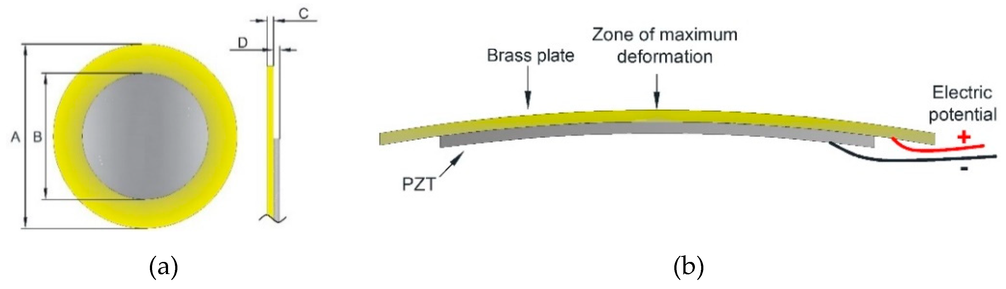
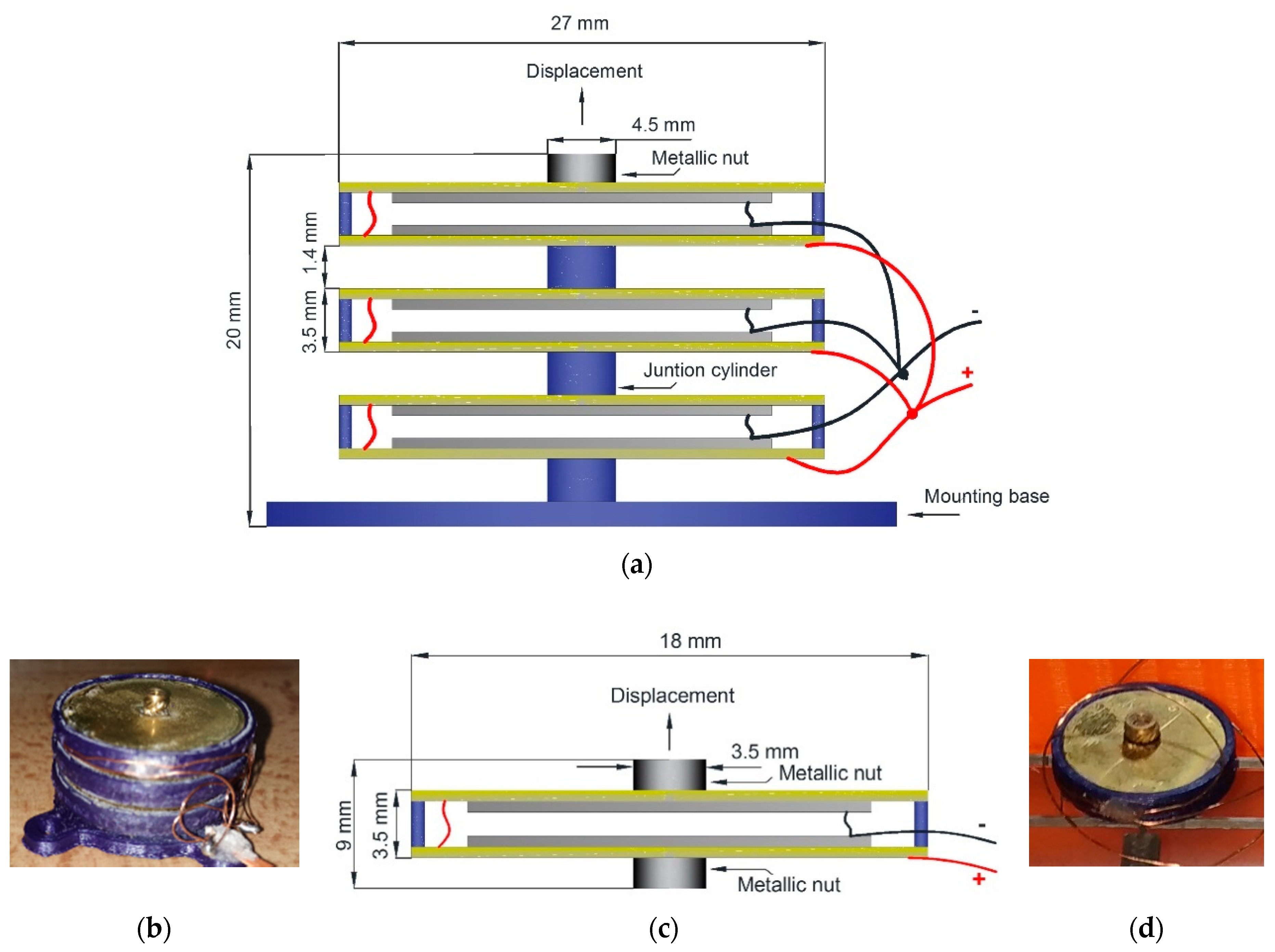
2. Piezoelectric Stack Actuators Design
3. Micropositioning Design
- Support for piezo buzzer stack actuators.
- A working platform (mobile support), where the samples are placed.
- A set of flexible elements for the movement on the X-axis.
- A group of flexible elements for the movement on the Y-axis.
- The Z-axis piezo buzzer stack actuator is located above the work platform.
3.1. Micropositioner Model
3.2. Displacement on Y-Axis
3.3. Displacement on X-Axis
4. Micromicropositioner Simulation
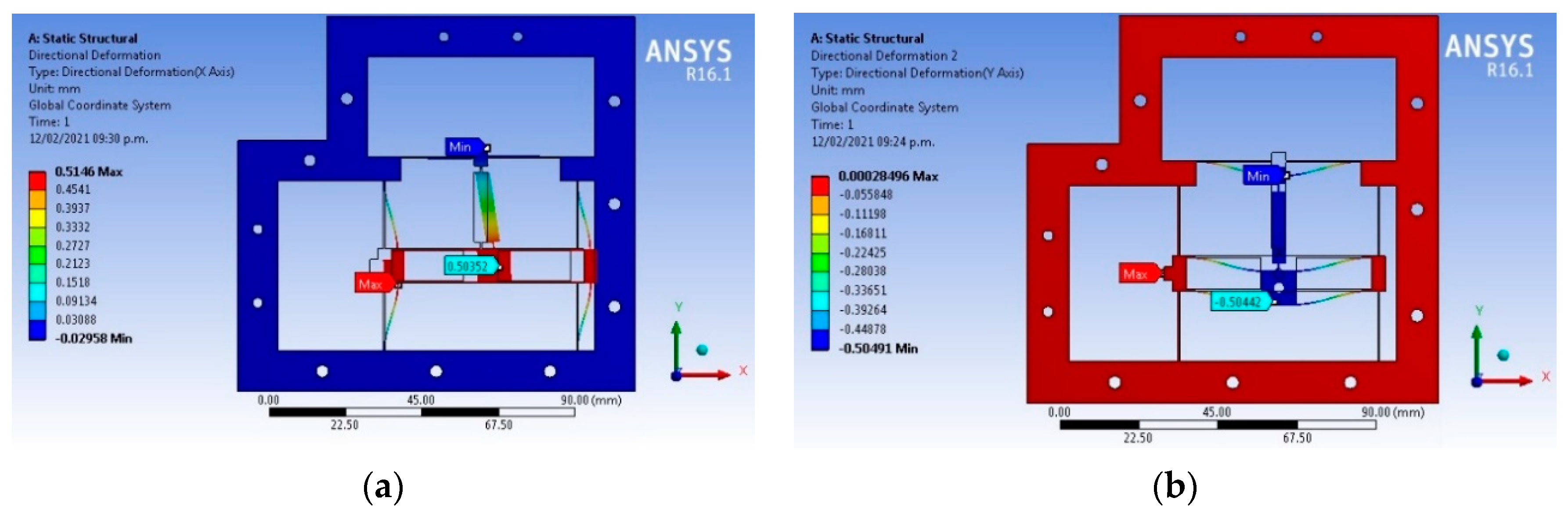
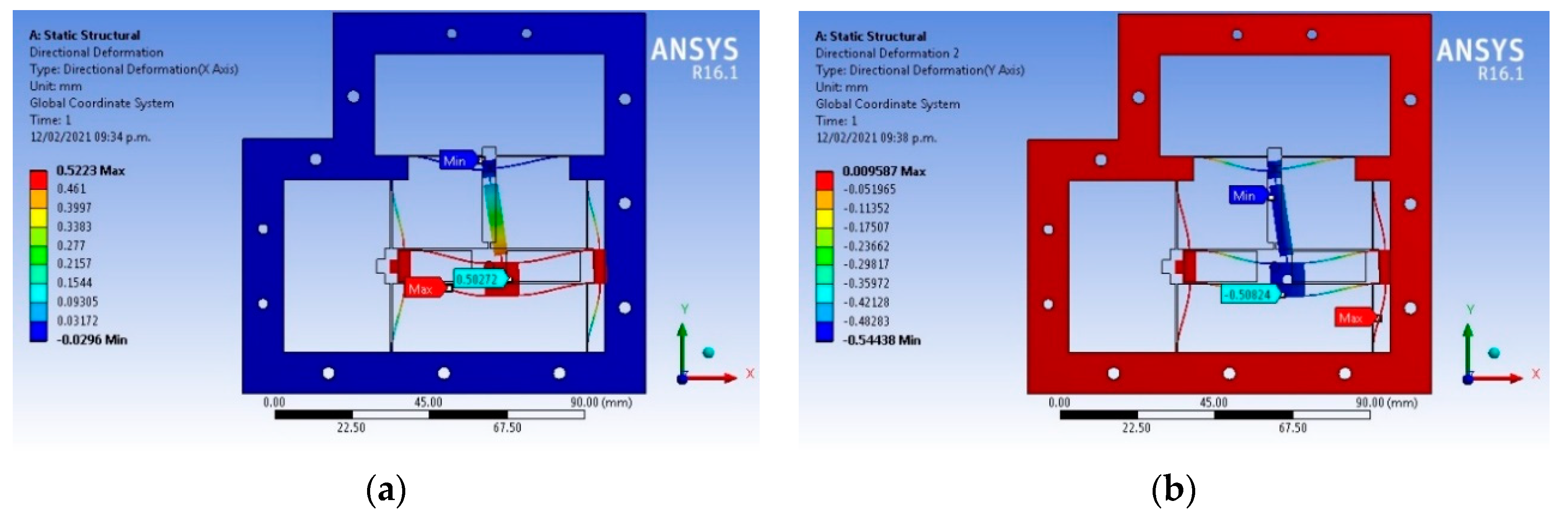
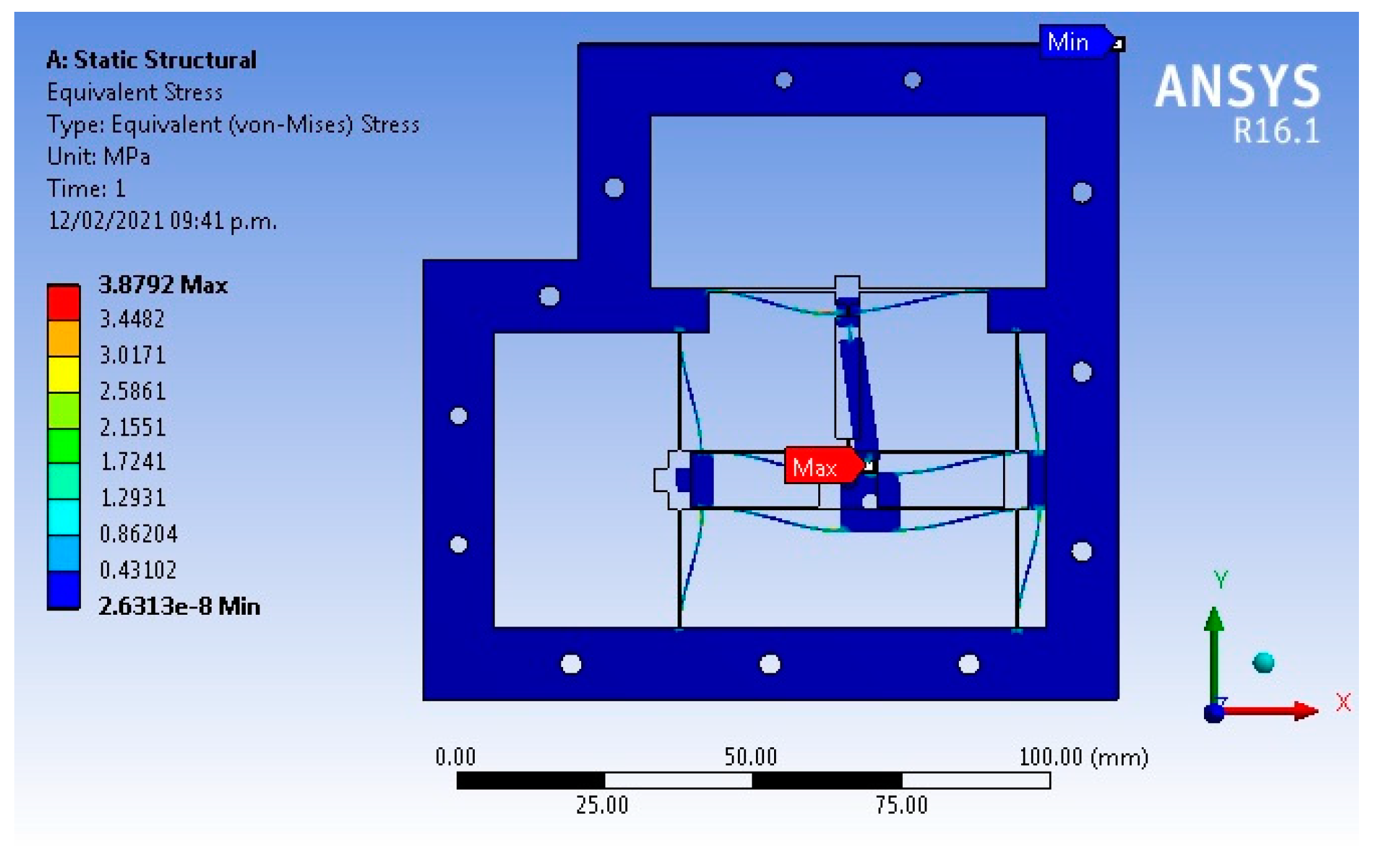
4.1. Static Structural Analysis
4.2. Modal Analysis
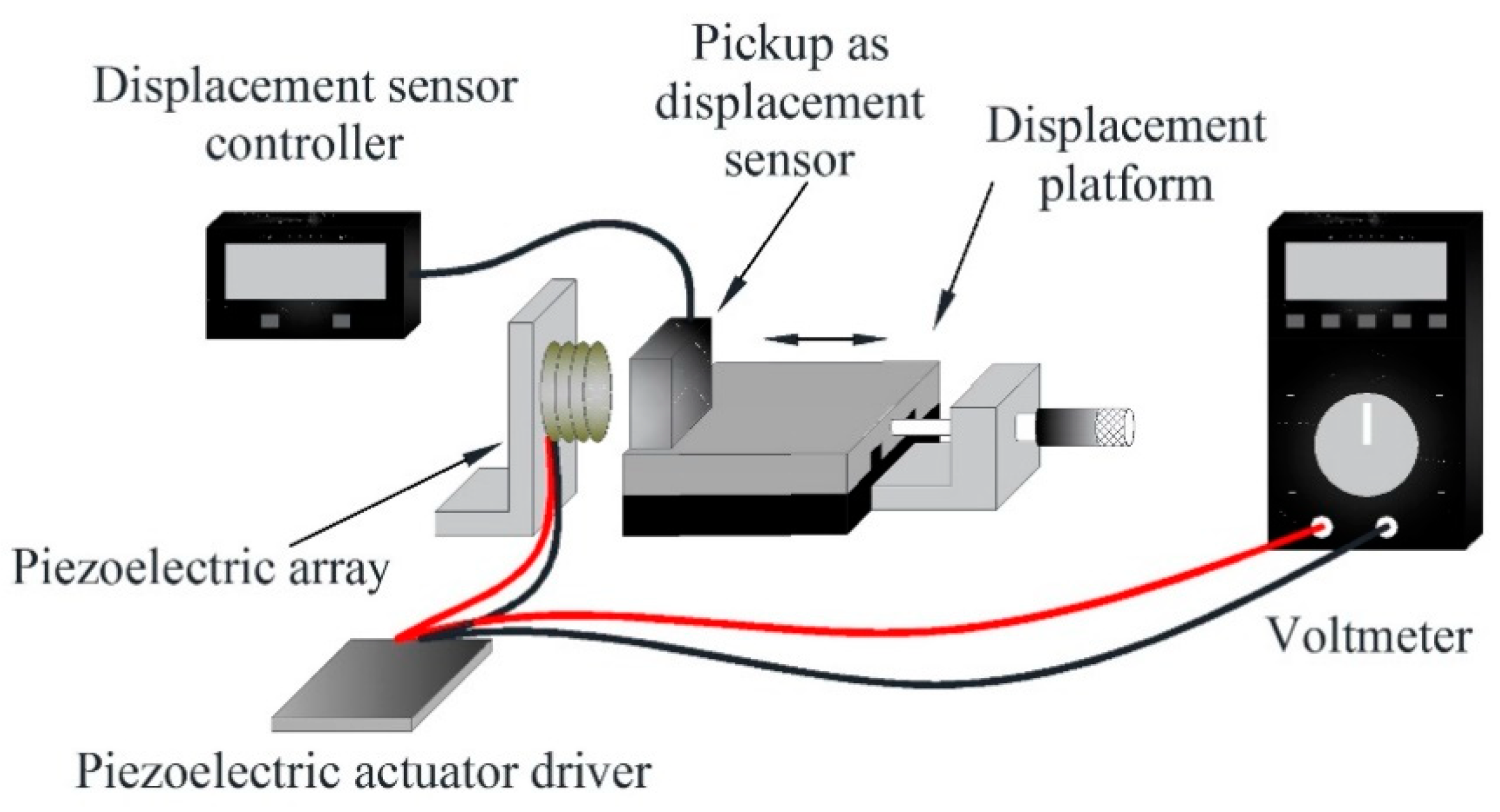
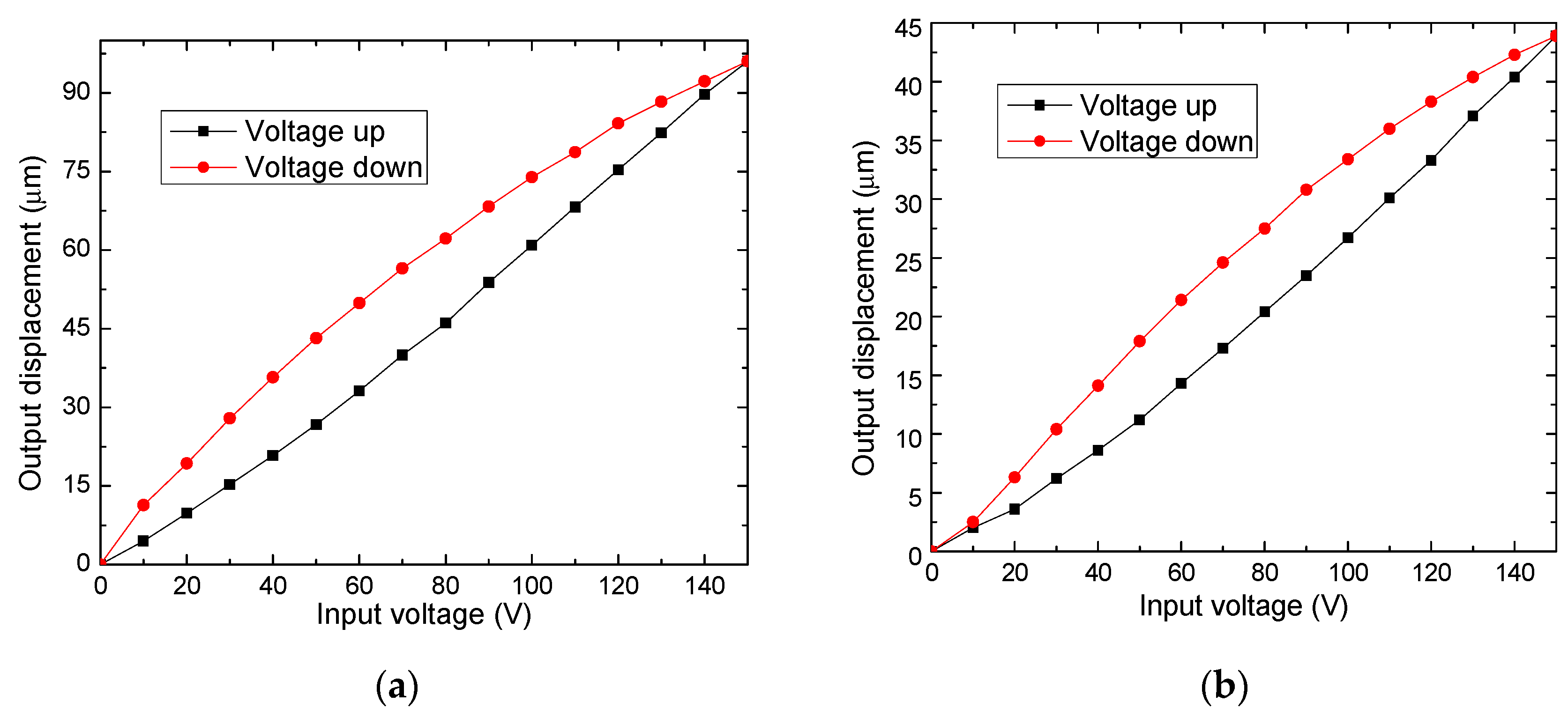
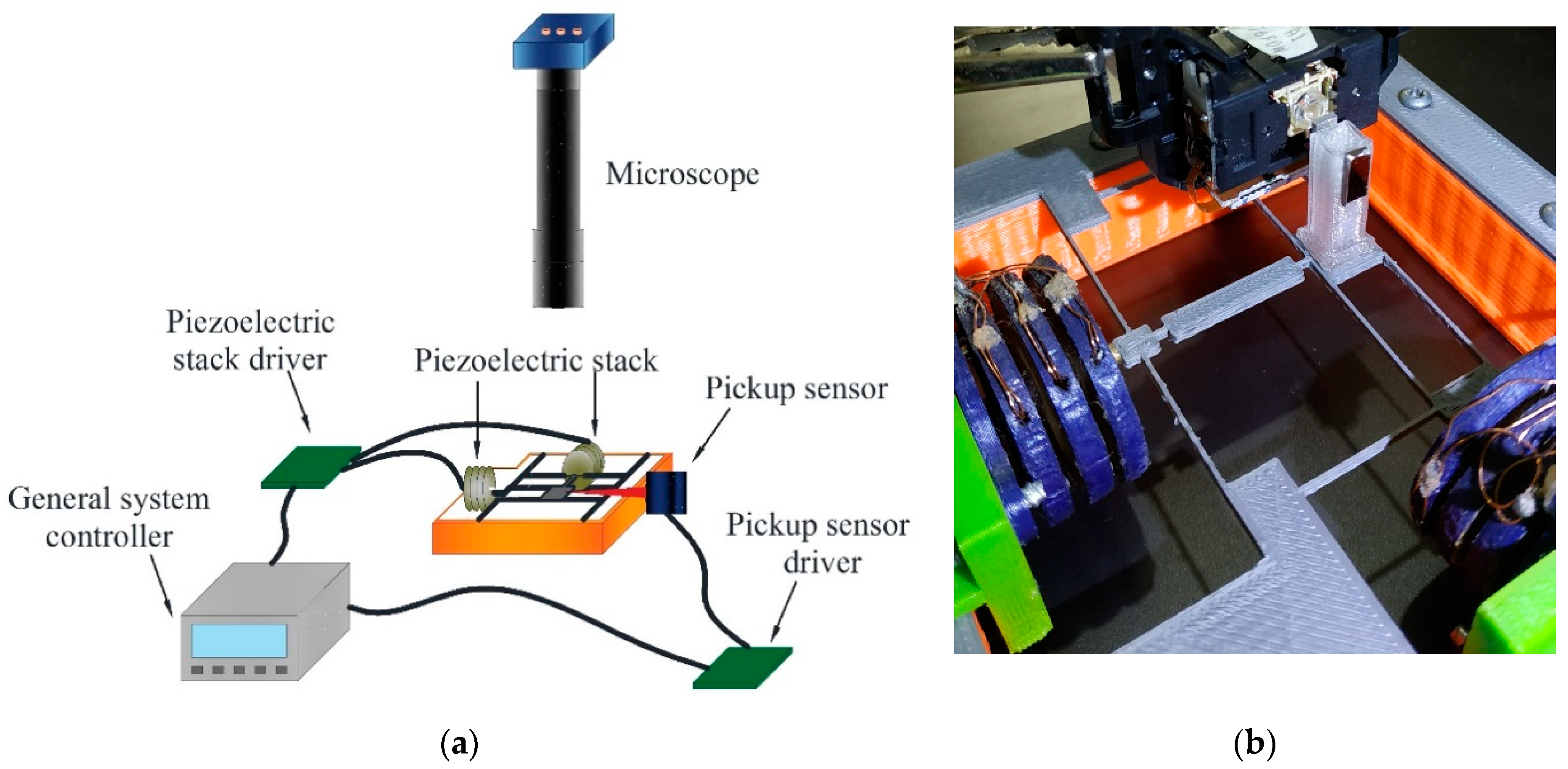
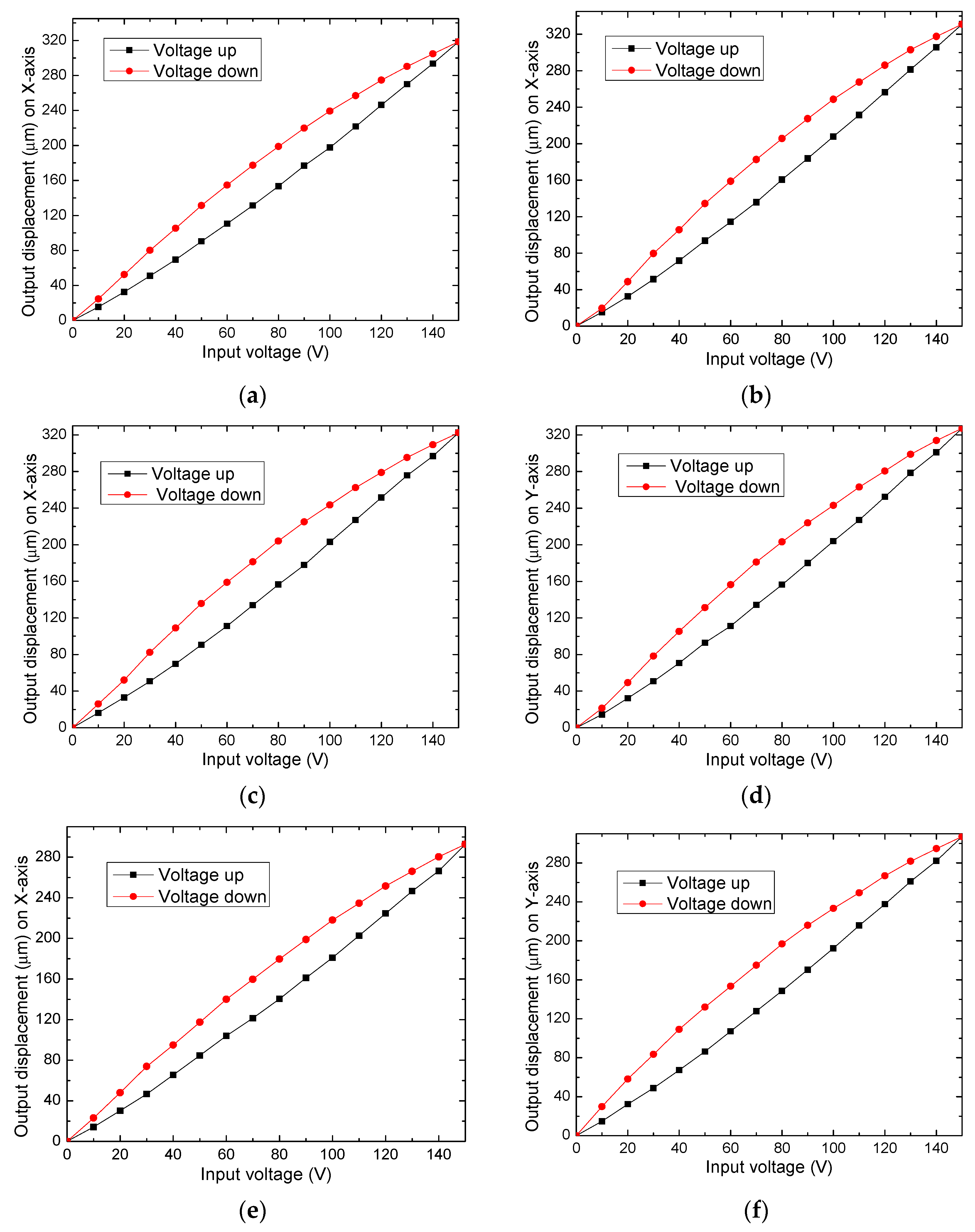
5. Experimental Results
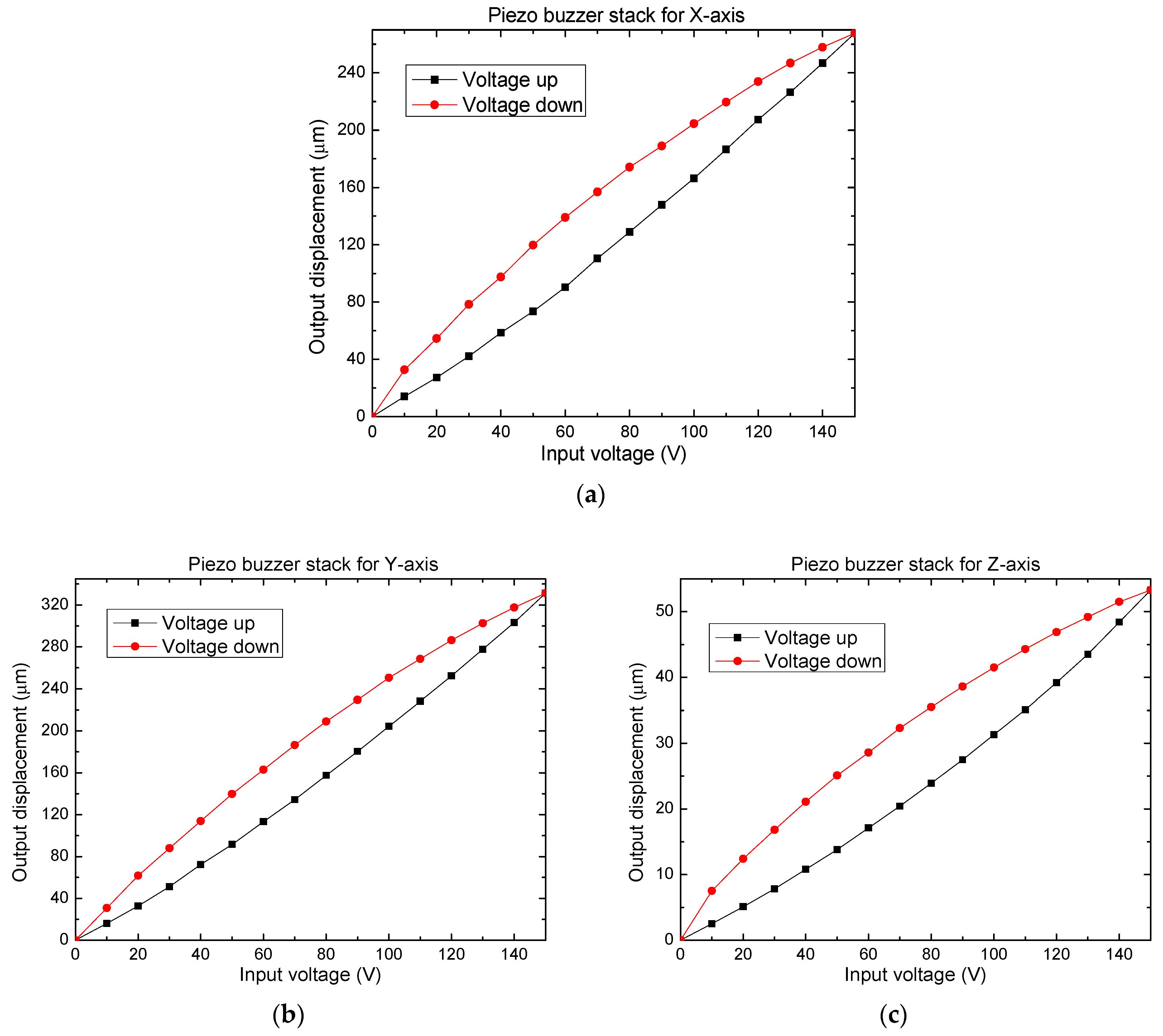
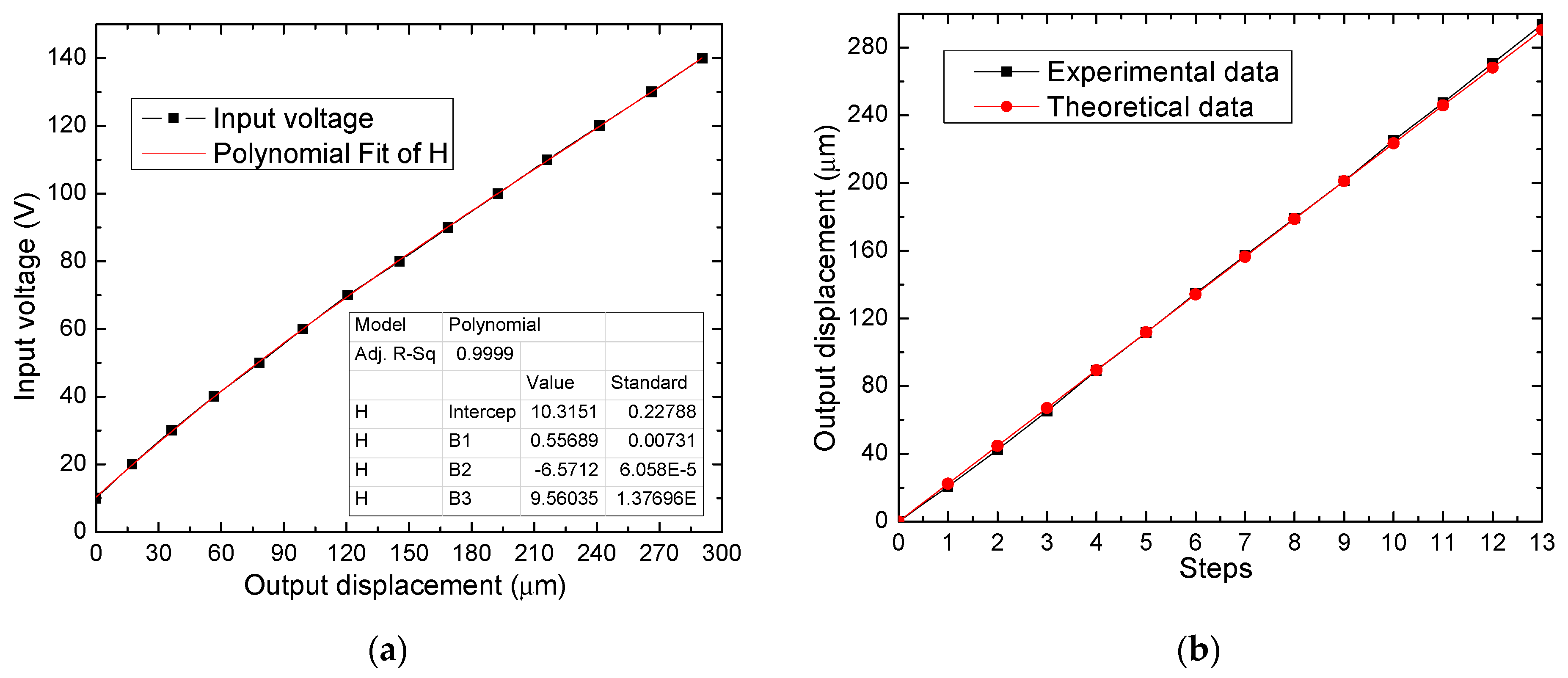
Linearization of Displacement of the Piezoelectric Actuator
6. Conclusions
Author Contributions
Funding
Institutional Review Board Statement
Informed Consent Statement
Conflicts of Interest
References
- Muro, H. History and Recent Progress of MEMS Physical Sensors. Adv. Sci. Technol. 2012, 81, 1–8. [Google Scholar] [CrossRef]
- Sitapure, N.A.; Malani, S.; Goswami, P.A. Review of the Foundation Technologies of Nano-Electronics. Int. J. Appl. Sci. Eng. 2016, 5, 29–42. [Google Scholar]
- Daffé, K.; Dambrine, G.; von Kleist-Retzow, F.; Haddadi, K. Impact of piezoelectric nano-positioner displacement accuracy on On-wafer S parameters repeatabilities. EMPIR Project 14IND02 PlanarCal. EMPIR Euramet Germany. Available online: https://planarcal.ptb.de/fileadmin/documents/empir/14Ind02/documents/Meetings/20160623_Delft/presentation_workshop_230616_dambrine.pdf (accessed on 13 March 2021).
- Jia, Y.; Xu, Q. MEMS Microgripper Actuators and Sensors: The State-of-the-Art Survey. Recent Patents Mech. Eng. 2013, 6, 132–142. [Google Scholar] [CrossRef] [Green Version]
- Liu, Y.; Deng, J.; Su, Q. Review on Multi-Degree-of-Freedom Piezoelectric Motion Stage. IEEE Access 2018, 6, 59986–60004. [Google Scholar] [CrossRef]
- Shi, C.; Luu, D.K.; Yang, Q.; Liu, J.; Chen, J.; Ru, C.; Xie, S.; Luo, J.; Ge, J.; Sun, Y. Recent advances in nanorobotic manipulation inside scanning electron microscopes. Microsyst. Nanoeng. 2016, 2, 16024. [Google Scholar] [CrossRef] [PubMed] [Green Version]
- Wu, Z.; Xu, Q. Survey on Recent Designs of Compliant Micro-/Nano-Positioning Stages. Actuators 2018, 7, 5. [Google Scholar] [CrossRef] [Green Version]
- Chaillet, N.; Régnier, S. Microrobotics for Micromanipulation, 1st ed.; Wiley: Hoboken, NJ, USA, 2013; pp. 179–242. [Google Scholar] [CrossRef]
- Dochshanov, A.; Verotti, M.; Belfiore, N.P. A Comprehensive Survey on Microgrippers Design: Operational Strategy. J. Mech. Des. 2017, 139, 070801. [Google Scholar] [CrossRef]
- Xu, Q. A novel compliant micropositioning stage with dual ranges and resolutions. Sens. Actuators A Phys. 2014, 205, 6–14. [Google Scholar] [CrossRef]
- Sun, F.; Hao, Y.; Xu, F.; Jin, J.; Li, Q.; Tong, L.; Zhang, M.; Zhang, X. Proposal of An Equal-Stiffness and Equal-Stroke 2D Micro-Positioning Platform Driven by Piezoelectric Actuators. Actuators 2020, 9, 47. [Google Scholar] [CrossRef]
- Wan, S.; Xu, Q. Design and analysis of a new compliant XY micropositioning stage based on Roberts mechanism. Mech. Mach. Theory 2016, 95, 125–139. [Google Scholar] [CrossRef]
- Zhang, X.; Zhang, Y.; Xu, Q. Design and control of a novel piezo-driven XY parallel nanopositioning stage. Microsyst. Technol. 2017, 23, 1067–1080. [Google Scholar] [CrossRef]
- Kenton, B.J.; Leang, K.K. Design and Control of a Three-Axis Serial-Kinematic High-Bandwidth Nanopositioner. IEEE/ASME Trans. Mechatron. 2011, 17, 356–369. [Google Scholar] [CrossRef]
- Guo, Z.; Tian, Y.; Liu, C.; Wang, F.; Liu, X.; Shirinzadeh, B.; Zhang, D. Design and control methodology of a 3-DOF flexure-based mechanism for micro/nano-positioning. Robot. Comput. Manuf. 2015, 32, 93–105. [Google Scholar] [CrossRef] [Green Version]
- Al-Jodah, A.; Shirinzadeh, B.; Ghafarian, M.; Das, T.K.; Pinskier, J. Design, modeling, and control of a large range 3-DOF micropositioning stage. Mech. Mach. Theory 2021, 156, 104159. [Google Scholar] [CrossRef]
- Chen, B.; Lee, M.; Tong, H.; Hang, C.-C.; Guo, Y.; Weerasooriya, S. An H/sub/spl infin//almost disturbance de-coupling robust controller design for a piezoelectric bimorph actuator with hysteresis. IEEE Trans. Control Sys. Tech. 1999, 7, 160–174. [Google Scholar] [CrossRef] [Green Version]
- Verotti, M. A pseudo-rigid body model based on finite displacements and strain energy. Mech. Mach. Theory 2020, 149, 103811. [Google Scholar] [CrossRef]
- Lobontiu, N. Compliant Mechanisms: Design of Flexure Hinges, 1st ed.; CRC Press: Boca Raton, FL, USA, 2003; pp. 1–448. [Google Scholar]
- Nakic, C.; Bieker, J.; Lammle, D.; Winterstein, T.; Schlaak, H.F.; Schaumann, G.; Abel, T. Development of an electrothermal micro positioning platform for laser targets with two degrees of freedom. In Proceedings of the 2016 International Conference on Manipulation, Automation and Robotics at Small Scales (MARSS), Paris, France, 18–22 July 2016; pp. 1–5. [Google Scholar] [CrossRef]
- Suthisomboon, T.; Bargiel, S.; Rabenorosoa, K.; Pengwang, E. Design and Simulation of XZ MEMS Micropositioning with 3D-Complex Structure. In Proceedings of the 2020 Symposium on Design, Test, Integration & Packaging of MEMS and MOEMS (DTIP), Lyon, France, 15–26 June 2020; pp. 1–5. [Google Scholar] [CrossRef]
- Khan, M.U.; Prelle, C.; Lamarque, F.; Buttgenbach, S. Design and Assessment of a Micropositioning System Driven by Electromagnetic Actuators. IEEE/ASME Trans. Mechatronics 2016, 22, 551–560. [Google Scholar] [CrossRef]
- Asua, E.; García-Arribas, A.; Etxebarria, V. Micropositioning using shape memory alloy actuators. Eur. Phys. J. Spéc. Top. 2008, 158, 231–236. [Google Scholar] [CrossRef]
- Zhang, Q.; Zhao, J.; Shen, X.; Xiao, Q.; Huang, J.; Wang, Y. Design, Modeling, and Testing of a Novel XY Piezo-Actuated Compliant Micro-Positioning Stage. Micromachines 2019, 10, 581. [Google Scholar] [CrossRef] [PubMed] [Green Version]
- Safari, A.; Akdoǧan, E.K. Piezoelectric and Acoustic Materials for Transducer Applications, 1st ed.; Springer: Boston, MA, USA, 2008; 482p. [Google Scholar] [CrossRef]
- Gan, J.; Zhang, X.; Li, H.; Wu, H. Full closed-loop controls of micro/nano positioning system with nonlinear hysteresis using micro-vision system. Sens. Act. A Phys. 2017, 257, 125–133. [Google Scholar] [CrossRef]
- Mølhave, K.; Hansen, O. Electro-thermally actuated microgrippers with integrated force-feedback. J. Micromech. Microeng. 2005, 15, 1265–1270. [Google Scholar] [CrossRef]
- Kiourti, A.; Nikita, K.S. A review of in-body biotelemetry devices: Implantables, ingestibles, and injectables. IEEE T. Bio-Med. Eng. 2017, 64, 1422–1430. [Google Scholar] [CrossRef]
- Lee, S.H. Note: A 3D-printed flexure nanostage driven by piezo buzzers. Rev. Sci. Instrum. 2018, 89, 106106. [Google Scholar] [CrossRef] [PubMed]
- Uran, S.; Bratina, B.; Šafarič, R. A microfluidic rotational motor driven by circular vibrations. Micromachines 2019, 10, 809. [Google Scholar] [CrossRef] [Green Version]
- Tian, Y.; Ma, Y.; Wang, F.; Lu, K.; Zhang, D. A novel XYZ micro/nano positioner with an amplifier based on L-shape levers and half-bridge structure. Sens. Act. A Phys. 2020, 302, 111777. [Google Scholar] [CrossRef]
- Gao, J.; Zeng, Z.; Tang, H.; Chen, X.; Qiu, Q.; He, S.; He, Y.; Yang, Z. Design and assessment of a piezo-actuated 3-DOF flexible nanopositioner with large stroke. In Proceedings of the 2016 IEEE International Conference on Manipulation, Manufacturing and Measurement on the Nanoscale (3M-NANO), Chongqing, China, 18–22 July 2016; pp. 19–24. [Google Scholar] [CrossRef]
- Li, Y.; Xu, Q. A totally decoupled piezo-driven XYZ flexure parallel micropositioning stage for micro/nanomanipulation. IEEE T. Autom Sci. Eng. 2011, 8, 265–279. [Google Scholar] [CrossRef]
- Zhang, X.; Xu, Q. Design of a new flexure-based XYZ parallel nanopositioning stage. In Proceedings of the 2015 IEEE International Conference on Robotics and Biomimetics (ROBIO), Zhuhai, China, 6–9 December 2015; pp. 1962–1966. [Google Scholar] [CrossRef]
- Zhang, X.; Xu, Q. Mechanism design of a compact XYZ parallel flexure stage. In Proceedings of the 2015 IEEE International Conference on Information and Automation, Lijiang, China, 8–10 August 2015; pp. 953–957. [Google Scholar] [CrossRef]
- Nguyen, N.T.; Huang, X. Miniature valveless pumps based on printed circuit board technique. Sens. Act. A Phys. 2001, 88, 104–111. [Google Scholar] [CrossRef]
- Wang, W.; Huang, M.; Huang, K.Y.; Hwang, I.S.; Hwu, E.T. Low-voltage and high-performance buzzer-scanner based streamlined atomic force microscope system. Nanotechnology 2013, 24, 455503. [Google Scholar] [CrossRef]
- Guilleus, Q.; Leroy, E.; Eck, L.; Hafez, M. A compact design for ultrasonic piezoelectric motor with embedded strain wave reducer for high torque applications. In Proceedings of the IEEE International Ultrasonics Symposium (IUS), Washington, DC, USA, 6–9 September 2017; pp. 1–4. [Google Scholar] [CrossRef]
- Kaçar, A.; Özer, M.B.; Taşcioğlu, Y. A novel artificial pancreas: Energy efficient valveless piezoelectric actuated closed-loop insulin pump for T1DM. Appl. Sci. 2020, 10, 5294. [Google Scholar] [CrossRef]
- Ma, H.K.; Chen, R.H.; Hsu, Y.H. Development of a piezoelectric-driven miniature pump for biomedical applications. Sens. Act. A Phys. 2015, 234, 23–33. [Google Scholar] [CrossRef]
- Shabanian, A.; Goldschmidtboeing, F.; Vilches, S.; Phan, H.H.; Bhat Kashekodi, A.; Rajaeipour, P.; Woias, P. A novel piezo actuated high stroke membrane for micropumps. Microelectron. Eng. 2016, 158, 26–29. [Google Scholar] [CrossRef]
- Zhang, Y.H.; Lee, C.H. Piezoelectric energy harvesting pedal integrated with a compliant load amplifier. Adv. Mech. Eng. 2019, 11, 1–9. [Google Scholar] [CrossRef] [Green Version]
- Kim, J.; You, K.; Choe, S.H.; Choi, H. Wireless ultrasound surgical system with enhanced power and amplitude performances. Sensors 2020, 20, 4165. [Google Scholar] [CrossRef]
- Prasad, S.E.; Waechter, D.F.; Blacow, R.G.; King, H.W.; Yaman, Y. Application of piezoelectrics to smart structures. In Proceedings of the Il Eccomas Thematic Conf. on Smart Struct. and Mat., Lisbon, Portugal, 18–21 July 2005; pp. 1–16. [Google Scholar]
- CNC Routersource. Available online: http://www.cncroutersource.com/hobby-cnc-router.html (accessed on 14 March 2021).
- Hwu, E.T.; Hung, S.K.; Yang, C.W.; Huang, K.Y.; Hwang, I.S. Real-time detection of linear and angular displacements with a modified DVD optical head. Nanotechnology 2008, 19, 115501. [Google Scholar] [CrossRef]
- Li, Y.; Wu, K.; Ai, Z.J. A circuit design of high-precision micro-displacement sensor system for DVD pickup head. In Proceedings of the 2012 Symposium on Photonics and Optoelectronics, Shanghai, China, 21–23 May 2012; pp. 2–5. [Google Scholar] [CrossRef]
- Lee, S.H. Note: Compact and light displacement sensor for a precision measurement system in large motion. Rev. Sci. Instrum. 2015, 86, 086103. [Google Scholar] [CrossRef]
- Rotter, J.B. Some problems and misconceptions related to the construct of internal versus external control of reinforcement. J. Consult. Clin. Psychol. 1975, 43, 56–67. [Google Scholar] [CrossRef]
- Boonmee, C.; Kositanont, C.; Leejarkpai, T. Degradation of Poly (lactic acid) under Simulated Landfill Conditions. Environ. Nat. Resour. J. 2016, 14, 1–9. [Google Scholar] [CrossRef]
- Gonçalves de Moura, I.; Vasconcelos de Sá, A.; Lemos Machado Abreu, A.S.; Alves Machado, A.V. Bioplastics from agro wastes for food packing applications. In Nanotechnology in the Agri-Food Industry Volume 7 Food Packaging; Grumezescu, A.M., Ed.; Academic Press: London, UK, 2017; Chapter 8; pp. 223–263. [Google Scholar] [CrossRef]
- Li, J.; Sedaghati, R.; Dargahi, J.; Waechter, D. Design and development of a new piezoelectric linear Inchworm. Mechatronics 2005, 15, 651–681. [Google Scholar] [CrossRef]
- Zhang, Q.; Zhao, J.; Peng, Y.; Pu, H.; Yang, Y. A novel amplification ratio model of a decoupled XY precision positioning stage combined with elastic beam theory and Castigliano’s second theorem considering the exact loading force. Mech. Syst. Signal Pr. 2020, 136, 106473. [Google Scholar] [CrossRef]
- Liu, P.; Yan, P. A modified pseudo-rigid-body modeling approach for compliant mechanisms with fixed-guided beam flexures. Mech. Sc. 2017, 8, 359–368. [Google Scholar] [CrossRef] [Green Version]
- Zhang, J.X.J.; Hoshino, K. Mechanical transducers: Cantilevers, acoustic wave sensors, and thermal sensors. In Molecular Sensors and Nanodevices; Elsevier: Amsterdam, The Netherlands, 2019; pp. 311–412. [Google Scholar] [CrossRef]
- Kaajakari, V. Practical MEMS; Small Gear Publishing: Las Vegas, NV, USA, 2009; ISBN 978-0-9822991-0-4. [Google Scholar]
- Kim, J.; Kim, K.; Choe, S.H.; Choi, H. Development of an accurate resonant frequency controlled wire ultrasound surgical instrument. Sensors 2020, 20, 3059. [Google Scholar] [CrossRef]
- Tymrak, B.M.; Kreiger, M.; Pearce, J.M. Mechanical properties of components fabricated with open-source 3-D printers under realistic environmental conditions. Mater. Design. 2014, 58, 242–246. [Google Scholar] [CrossRef] [Green Version]
- Dhaliwal, G.S.; Dundar, M.A. Four Point Flexural Response of Acrylonitrile-Butadiene-Styrene. J. Compos. Sci. 2020, 4, 63. [Google Scholar] [CrossRef]
- Rybachuk, M.; Mauger, C.A.; Fiedler, T.; Öchsner, A. Anisotropic mechanical properties of fused deposition modeled parts fabricated by using acrylonitrile butadiene styrene polymer. J. Polym. Eng. 2017, 37, 699–706. [Google Scholar] [CrossRef]
- Tarrazó-Serrano, D.; Castiñeira-Ibáñez, S.; Sánchez-Aparisi, E.; Uris, A.; Rubio, C. MRI Compatible Planar Material Acoustic Lenses. Appl. Sci. 2018, 8, 2634. [Google Scholar] [CrossRef] [Green Version]
- Grupo XDS. Available online: https://octofiber.com/media/Octofiber_TDS_PETG-03.pdf (accessed on 13 February 2021).
- Mariaca Beltrán, Y.D.J.; Garcia Salmoran, I.A.; Clemente Mirafuente, C.M.; Rodriguez Ramirez, J.A.; Acosta Flores, M.; Garcia Castrejon, J.C. Nueva metodología para el análisis de sistemas mecánicos utilizando modelos a escala y leyes de similitud. DYNA Ing. Ind. 2019, 94, 59–66. [Google Scholar] [CrossRef]
- PLA Ultimaker. Available online: https://www.3dmarket.mx/wp-content/uploads/2021/01/Ultimaker-PLA.pdf (accessed on 13 February 2021).
- Repositorio Uisek. Available online: https://repositorio.uisek.edu.ec/bitstream/123456789/2792/9/CALIDAD%20DE%20MALLA.pdf (accessed on 13 March 2021).
- Espinosa, H.D.; Zavattieri, P.D.; Emore, G.L. Adaptive FEM computation of geometric and material nonlinearities with application to brittle failure. Mech. Mater. 1998, 29, 275–305. [Google Scholar] [CrossRef]
- Comsol.com. Available online: https://www.comsol.com/blogs/what-is-geometric-nonlinearity/ (accessed on 13 March 2021).
- Geng, Z.J.; Haynes, L.S. Six DOF active vibration control using Stewart platform. IEEE Trans Control Syst. Technol. 1994, 2, 45–53. [Google Scholar] [CrossRef]
- Riepold, M.; Maslo, S.; Han, G.; Henke, C.; Trächtler, A. Open-loop linearization for piezoelectric actuator with inverse hysteresis model. Vib. Proced. 2019, 22, 47–52. [Google Scholar] [CrossRef]


| Ref. | Material | Amplification Factor | Maximum Displacement X, Y, Z (µm) | Resolution (nm) | Frequency (Hz) |
|---|---|---|---|---|---|
| [31] | Al 7075 | 8.1 | 128.1, 131.3, 17.9 (experimental) | 8 | 262.8 and 365.9 (modal freq.) |
| [32] | Al/7075 | 7.1 | 710 in all axes (simulation) | - | 76.4, 76.5, 79.6, 274.1, 326.7, 326.8 (modal freqs. (FEA)) |
| [33] | Al/7075 | 8.29 | 165.8, 5.4, 6.5 (experimental) | 180 | 49.59 (modal freq. (FEA)) |
| [34] | Al/7075 | 15.3 | 153 in all axes (simulation) | - | - |
| [35] | Al/7075 | 9.31 | 120 in all axes (simulation) | - | 226 (modal freq.) |
| [14] | Al/7075 | 1 | 9, 9, 1 (experimental) | 90 | 7000 (operation freq.) |
| Buzzer Actuator (For Axis) | Size A (mm) | Size B (mm) | Size C (mm) | Size D (mm) | Resonance Frequency (kHz) | Resonance Impedance (Ω) | Static Capacitance (nF) |
|---|---|---|---|---|---|---|---|
| X, Y | 27 | 18.5 | 0.2 | 0.10 | 3.5 | ≤300 | 18 |
| Z | 18 | 14.5 | 0.2 | 0.10 | N. A. | N. A. | 11 |
| Buzzer Actuator (For Axis) | Measured Individual Piezo Buzzer Displacement (µm) | Measured Piezo Buzzer Stack Displacement (µm) | % of Increase | Calculated Piezo Buzzer Stack Displacement (µm) | % of Error (Measured and Calculated Stack Displacement) |
|---|---|---|---|---|---|
| X and Y axes (average) | 96 | 300 | 312.5 | 576 | 47.9 |
| Z-axis | 43.9 | 53.3 | 121.4 | 87.8 | 39.2 |
| Stacks of 4 Piezo Buzzers | Stacks of 6 Piezo Buzzers | |||||
|---|---|---|---|---|---|---|
| Stack 1 | Stack 2 | Average | Stack 1 | Stack 2 | Average | |
| % of error (measured and calculated) | 48.4 | 44.0 | 46.2 | 42.4 | 53.5 | 47.9 |
| Buzzer Actuator for | Measured Individual Piezo Buzzer Force (N) | Measured Piezo Buzzer Stack Force (N) | % of Increase | Calculated Piezo Buzzer Stack Force (N) | % of Error of Piezo Buzzer Stack Force |
|---|---|---|---|---|---|
| X and Y axes (average value) | 0.424 | 1.275 | 300.7 | 2.544 | 49.8 |
| Z-axis | 0.239 | 0.315 | 131.7 | 0.478 | 34.1 |
| Parameter and Units | ABS | PETG | PLA |
|---|---|---|---|
| Young Modulus, (GPa) | 1.807 | 2.15 | 3.5 |
| Poisson’s Ratio | 0.38 | 0.4 | 0.4 |
| Field Yield Strength, (MPa) | 21 | 50 | 72 |
| Ultimate tensile strength, (MPa) | 22 | 60 | 26.4 |
| Density, (kg/m3) | 1050 | 1270 | 1250 |
| Melting point, (°C) | 225–245 | 135 | 145–177 |
| Force | ABS | PETG | PLA | |||||||
|---|---|---|---|---|---|---|---|---|---|---|
| X (N) | Y (N) | Displacement X (µm) | Displacement Y (µm) | Maximum Equivalent Stress (MPa) | Displacement X (µm) | Displacement Y (µm) | Maximum Equivalent Stress (MPa) | Displacement X (µm) | Displacement Y (µm) | Maximum Equivalent Stress (MPa) |
| 0.1 | 0 | 503 | −1.13 | 3.82 | 420 | 2.48 | 3.83 | 257 | −1.1 | 3.83 |
| 0 | 0.1 | −38.1 × 10⁻³ | −504 | 2.77 | −15.7 × 10⁻³ | −422 | 2.78 | −16.1 × 10⁻³ | −259 | 2.78 |
| 0.1 | 0.1 | 502 | −508 | 3.87 | 420 | −423 | 3.9 | 257 | −260 | 3.9 |
| Type of Analysis (Force = 0.1 N) | ABS | PETG | PLA | |||
|---|---|---|---|---|---|---|
| Displacement on X | Displacement on Y | Displacement on X | Displacement on Y | Displacement on X | Displacement on Y | |
| Simulation (µm) | 503 | 504 | 420 | 422 | 257 | 259 |
| Analytical (µm) | 519.6 | 482.0 | 436.7 | 403.1 | 268.1 | 248.8 |
| Experimental (µm) | 290.1 | 372.1 | 253.8 | 271.4 | 131.2 | 226.2 |
| % of error (simulation and analytical) | 3.3 | 4.3 | 3.9 | 4.4 | 4.3 | 3.9 |
| % of error (simulation and experimental) | 42.3 | 26.1 | 39.5 | 35.6 | 48.9 | 12.6 |
| Device | Solver Target | Element Type/Mesh | Inflation | Statistic | Total Mass (g) | |||||
|---|---|---|---|---|---|---|---|---|---|---|
| No. of Total Nodes | No. of Total Elements | Mesh | ||||||||
| Transition Ratio | Max. Layers | Growth Rate | Skewness | Orthogonal Quality | ||||||
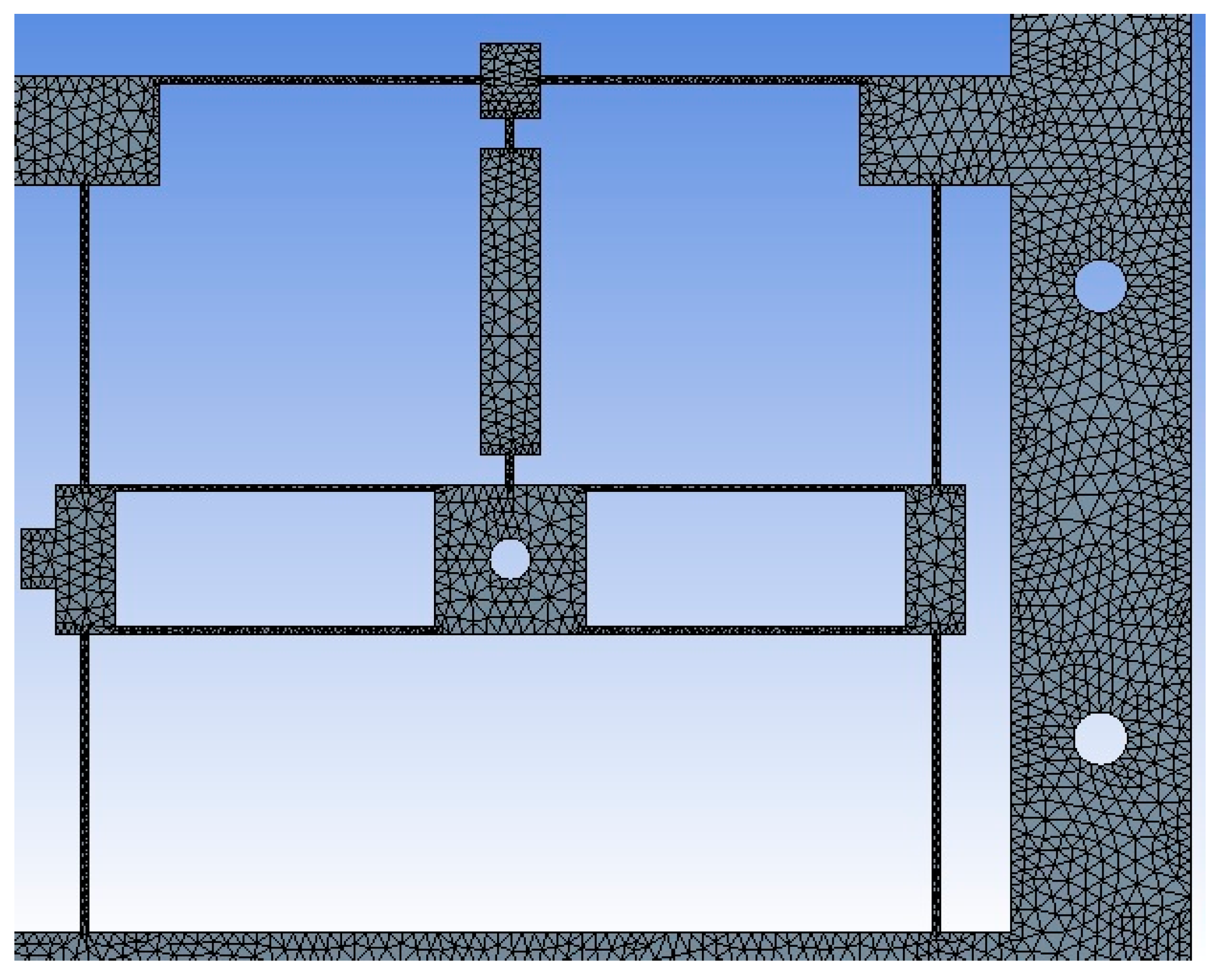
| Micropositioner | Mechanical APDL | SOLID 187/Refinement Controlled program (Tet10) | 0.272 | 5 | 1.2 | 100,545 | 49,867 | Average | ABS 8.36 | |
| 0.47515 | 0.73378 | |||||||||
| Standard deviation | PETG 10.11 | |||||||||
| 0.15667 | 0.1138 | PLA 9.96 | ||||||||
| Micropositioning platform implemented with PLA. | ||
 |  |  |
| 1st Modal frequency = 137.87 Hz | 2nd Modal frequency = 152.13 Hz | 3rd Modal frequency = 194.17 Hz |
| Micropositioning platform implemented with PETG. | ||
 |  |  |
| 1st Modal frequency = 107.57 Hz | 2nd Modal frequency = 118.58 Hz | 3rd Modal frequency = 151.07 Hz |
| Micropositioning platform implemented with ABS. | ||
 |  |  |
| 1st Modal frequency = 108.33 Hz | 2nd Modal frequency = 119.46 Hz | 3rd Modal frequency = 152.43 Hz |
| Device | Solver Target | Element Type/Mesh | Statistics | |||
|---|---|---|---|---|---|---|
| No. of Total Nodes | No. of Total Elements | Skewness | Orthogonal Quality | |||
| Micropositioner | Mechanical APDL | SOLID 187/Face sizing -> element size = 1 × 10⁻⁴ m | 974,283 | 556,583 | Average | |
| 0.432 | 0.565 | |||||
| Standard deviation | ||||||
| 0.191 | 0.188 | |||||
| Positioner | Displacements on the X-axis, (µm) | Decrease (%) | Frequency (Hz) | Increment (%) |
|---|---|---|---|---|
| ABS (reference) | 502 | N. A | 108.33 | N.A. |
| PETG | 420 | 16.4 | 107.67 Hz | −0.6 |
| PLA | 257 | 48.8 | 137.87 | 27.26 |
| Material | Displacements on the X-Axis, (µm) | Displacements on the Y-Axis, (µm) | % of Error |
|---|---|---|---|
| ABS | 318.5 | 331 | 3.92 |
| PETG | 322.4 | 327.3 | 1.52 |
| PLA | 292.7 | 307.1 | 4.92 |
Publisher’s Note: MDPI stays neutral with regard to jurisdictional claims in published maps and institutional affiliations. |
© 2021 by the authors. Licensee MDPI, Basel, Switzerland. This article is an open access article distributed under the terms and conditions of the Creative Commons Attribution (CC BY) license (http://creativecommons.org/licenses/by/4.0/).
Share and Cite
Ferrara-Bello, A.; Vargas-Chable, P.; Vera-Dimas, G.; Vargas-Bernal, R.; Tecpoyotl-Torres, M. XYZ Micropositioning System Based on Compliance Mechanisms Fabricated by Additive Manufacturing. Actuators 2021, 10, 68. https://doi.org/10.3390/act10040068
Ferrara-Bello A, Vargas-Chable P, Vera-Dimas G, Vargas-Bernal R, Tecpoyotl-Torres M. XYZ Micropositioning System Based on Compliance Mechanisms Fabricated by Additive Manufacturing. Actuators. 2021; 10(4):68. https://doi.org/10.3390/act10040068
Chicago/Turabian StyleFerrara-Bello, Andres, Pedro Vargas-Chable, Gerardo Vera-Dimas, Rafael Vargas-Bernal, and Margarita Tecpoyotl-Torres. 2021. "XYZ Micropositioning System Based on Compliance Mechanisms Fabricated by Additive Manufacturing" Actuators 10, no. 4: 68. https://doi.org/10.3390/act10040068