
Planar Micro-Positioning Device Based on a 3D Digital Electromagnetic Actuator
by
 , , ,
, , ,
Ajinkya Deshmukh
*,† ,
,
Laurent Petit
*,†,
Muneeb-ullah Khan
,
Frédéric Lamarque
and
Christine Prelle
† University of Technology of Compiègne (UTC), Roberval Laboratory (Mechanics, Energy and Electricity), Royallieu Research Center, CS 60319, 60203 Compiègne, France
*
Authors to whom correspondence should be addressed.
†
These authors contributed equally to this work.
Actuators 2021, 10(12), 310; https://doi.org/10.3390/act10120310
Submission received: 19 October 2021
/
Revised: 18 November 2021
/
Accepted: 22 November 2021
/
Published: 25 November 2021
(This article belongs to the Section Precision Actuators)
Abstract
:In this paper, a novel micro-positioning device based on a 3D digital actuator is presented. The proposed system allows realizing planar motions of micro-objects, which could be implemented in several applications where micro-positioning tasks are needed such as micro-component manufacturing/assembly, biomedicine, scanning microscopy, etc. The device has three degrees of freedom, and it is able to achieve planar motions of a mobile plate in the xy-plane at two different levels along the z-axis. It consists of a hexagonal mobile part composed of a permanent magnet that can reach twelve discrete positions distributed between two z-axis levels (six at each level). Two different approaches are presented to perform positioning tasks of the plate using the digital actuator: the stick-slip and the lift-mode approaches. A comparison between these two approaches is provided on the basis of the plate displacement with respect to different current values and conveyed mass. It was observed that for a current of 2 A, the actuator is able to displace a mass of 1.15 g over a distance of 0.08 mm. The optimal positioning range of the planar device was found to be ±5.40 mm and ±7.05 mm along the x- and y-axis, respectively.
1. Introduction
Micro-positioning devices enable precise motions of micro-objects from one point to another one, generally in the xy-plane. These devices play a key role in the micro-manipulation tasks in micro-factories to ensure the positioning of objects between different manufacturing and assembly stations. The performances of these stations and of the micro-factory are strongly dependent on the characteristics of these micro-positioning devices such as the production rate, flexibility, precision, and energy consumption. Different architectures of micro-positioning devices can be found in the literature and can be classified according to their architecture, either long-range actuators [1,2,3,4,5] or on an array of short-range actuators [6,7,8,9,10]. Positioning with the help of long-range actuators is mostly carried out using the analogical principle due to their high precision and good position repeatability. This principle includes actuators that can reach any position within their working range. However, such actuators require the use of feedback sensors with closed-loop control to ensure their positioning precision. The integration of such sensors could be difficult, in particular in compact systems.
The second architecture of micro-positioning devices is based on an array of short-range actuators. The actuators of such an array can be based on a digital principle [11]. This kind of actuator is open-loop-controlled and does not require any feedback sensor to measure the actuator displacement. Digital actuators have a fixed number of discrete positions, generally two as the bistable actuators, that characterize the actuator stroke. To ensure a digital behavior, the discrete positions need to be highly repeatable and are defined during the manufacturing process of such actuators. As a consequence, the manufacturing techniques have a high influence on the actuator performance. Digital actuators are also energy efficient as they only need energy to switch between the discrete positions and there is no energy consumption when the mobile part remains stationary at a discrete position [12]. This behavior is particularly interesting in order to avoid any disturbances in the actuator functioning.
Two main functions are necessary to ensure the working of a digital actuator: the switching and holding functions. The switching function enables the switch of the mobile part between the discrete positions. This function is carried out using several physical principles such as the electromagnetic [13,14,15,16,17], electro-thermal [18,19,20,21,22], piezoelectric [7,23,24,25,26,27,28], and electrostatic principles [29,30,31,32,33,34]. The holding function corresponds to the holding of a mobile part at any of the discrete positions to ensure the actuator’s repeatability and the digital behavior even in the presence of disturbances. In the literature, several solutions have been employed to realize this function using magnetic holding [35,36], compliant structures [37], and locking actuators [38].
In our previous work [13], a planar motion device based on a digital actuators array was presented. This device was based on digital actuators with a square architecture with four discrete positions, which enabled 2D motions. In the present paper, a short-range positioning device based on a 3D electromagnetic digital actuator is presented. The proposed work presents two main originalities. The first one is related to its architecture: the z-axis displacement allows reaching positions at two levels, and the hexagonal shape enables six discrete positions at each level, which leads to twelve discrete positions in total. The second originality is related to the possibility of generating motions with two different positioning approaches, lift-mode and stick-slip. The objective of the paper is to present the 3D hexagonal architecture of the actuator and to validate the ability to realize planar motions. In Section 2, the design and working principle of the 3D digital actuator are explained. The design of the device was realized with the help of a magnetic and electromagnetic modeling, described in Section 3. Section 4 provides a prototype description and an experimental characterization of the performances using two different approaches. Finally, Section 5 summarizes the work and provides future perspectives.
2. Design and Working Principle of the Positioning Device
2.1. Description of the Digital Actuator
This section provides a detailed description of the 3D digital actuator. Its mobile part consists of a hexagonal Mobile Permanent Magnet (MPM) placed in a fixed hexagonal cavity. A z-axis retainer is fixed at the bottom of the MPM to define the actuator stroke along the z-axis (Figure 1a).
The retainer also prevents the MPM from going out of the cavity. Two plates (top and second) are stacked together to form the hexagonal cavity and to obtain the z-axis stroke. The fixed part of the actuator integrates six cylindrical Fixed Permanent Magnets (FPMs) placed around the MPM cavity. The magnetic orientations for the FPMs are upturned compared to that of the MPM in order to obtain a magnetic attraction force between the MPM and the FPMs at each discrete position. This holding force helps the MPM remain at any of the discrete position without any energy consumption. There are in total twelve discrete positions, which are distributed at two different levels along the z-axis, as shown in Figure 1b. Due to the standard hexagonal architecture of the actuator, different strokes are obtained in the xy-plane and are named as Short-x-stroke (a = 0.60 mm), Long-x-stroke (c = 1.20 mm), and y-Stroke (b = 1.04 mm). Moreover, the stroke along the z-axis (z-Stroke) is defined to be 0.5 mm (d).
A four-layer Printed Circuit Board (PCB) is placed beneath the hexagonal cavity in order to switch the MPM between the discrete positions in the xy-plane. The PCB build-up consists of two sets of three serially connected conductors placed on the top layer the and second layer for x-axis and y-axis switching, respectively (Figure 1c), whereas, the third and fourth layers are used for routing purpose. Three conductors are used in each direction to ensure the generation of sufficient electromagnetic force to switch the MPM. A thin glass layer (thickness = 170 m) is placed between the PCB and the MPM for electrical insulation and also to provide a smooth surface for switching. The lower and upper z-axis levels are called z and z, respectively.
The switching along the z-axis is obtained with the help of a current-carrying electromagnetic air core coil placed beneath the PCB. An air core coil is considered to avoid any attraction between the MPM and the ferrite core. Unlike the switching in the xy-plane, which is obtained with pulsed current signals, a continuous current is needed to switch the MPM along the z-axis and to maintain it at the z level. The continuous current in the coil serves also as a holding current for the MPM at the z level. At the z level, the MPM remains at any position under the action of its own weight and with the help of the magnetic holding generated by the six FPMs. The details about the dimensional and magnetic properties are shown in Table 1.
2.2. Displacement Approaches
A mobile plate (15 × 1 mm; mass = 0.26 g) is placed on top of the actuator, as shown in Figure 1, and it is displaced with the help of the MPM. The architecture helps to propose two different displacement approaches (stick-slip and lift-mode), as described in the following paragraphs.
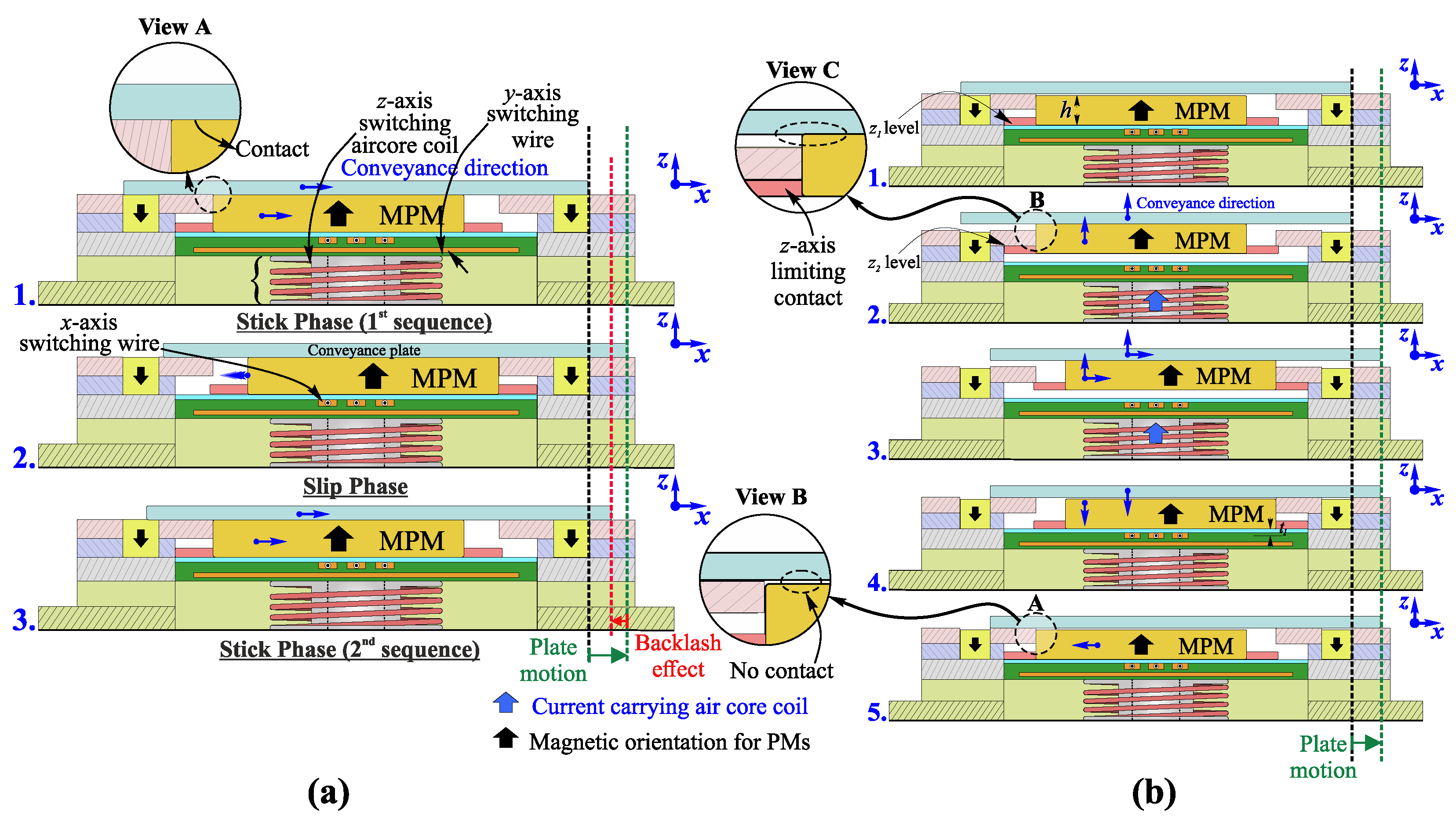
2.2.1. Stick-Slip Approach
In this approach, the MPM is always in contact with the mobile plate, which can be moved along the x- or y-axis at both levels along the z-axis (z (coil not excited) or z (coil excited)). The step-by-step displacement sequence is shown in Figure 2a for a displacement along the x-axis. In the figure, the MPM is initially located in the left position, and a low driving current value is firstly used to switch it along the + x-axis. This low driving current limits the MPM acceleration and then maximizes the energy transfer between the MPM and the plate, which is then moved along the + x-axis. In the second step, the MPM is switched back to the original position with a high driving current in the opposite direction. This high current ensures a slipping between the MPM and the plate due to a minimization of the energy transfer and then a return of the MPM to its initial position with a minimum disturbance on the plate. After the MPM has returned to its initial position, a new displacement sequence can be realized.
2.2.2. Lift-Mode Approach
In this approach, the MPM is not always in contact with the mobile plate, and its motion can only be obtained at the z level. With this approach, the z-axis is used to ensure or avoid the physical contact between the plate and the MPM (no contact when the MPM is at the z level and in contact when the MPM is at the z level). This non-contact configuration is used when the actuator is switched back to its initial position, which avoids disturbance on the mobile plate. The working principle is detailed in Figure 2b for a displacement along the + x-axis. In the figure, the MPM is initially placed in the left position at the z level. In the first step, the MPM is switched from the z to the z level in order to ensure the contact between the MPM and the mobile plate. In the second step, the MPM is switched along the + x-axis with a low driving current value, which ensures the plate motion in the same direction. After that, the MPM is moved back to the z level to release the contact with the plate. In the fourth step, the MPM is switched back to its initial position without any disturbance to the plate, and then, the system is ready for the next conveyance sequence.
3. Modeling of the Positioning Device
3.1. Magnetic Flux Density Calculation
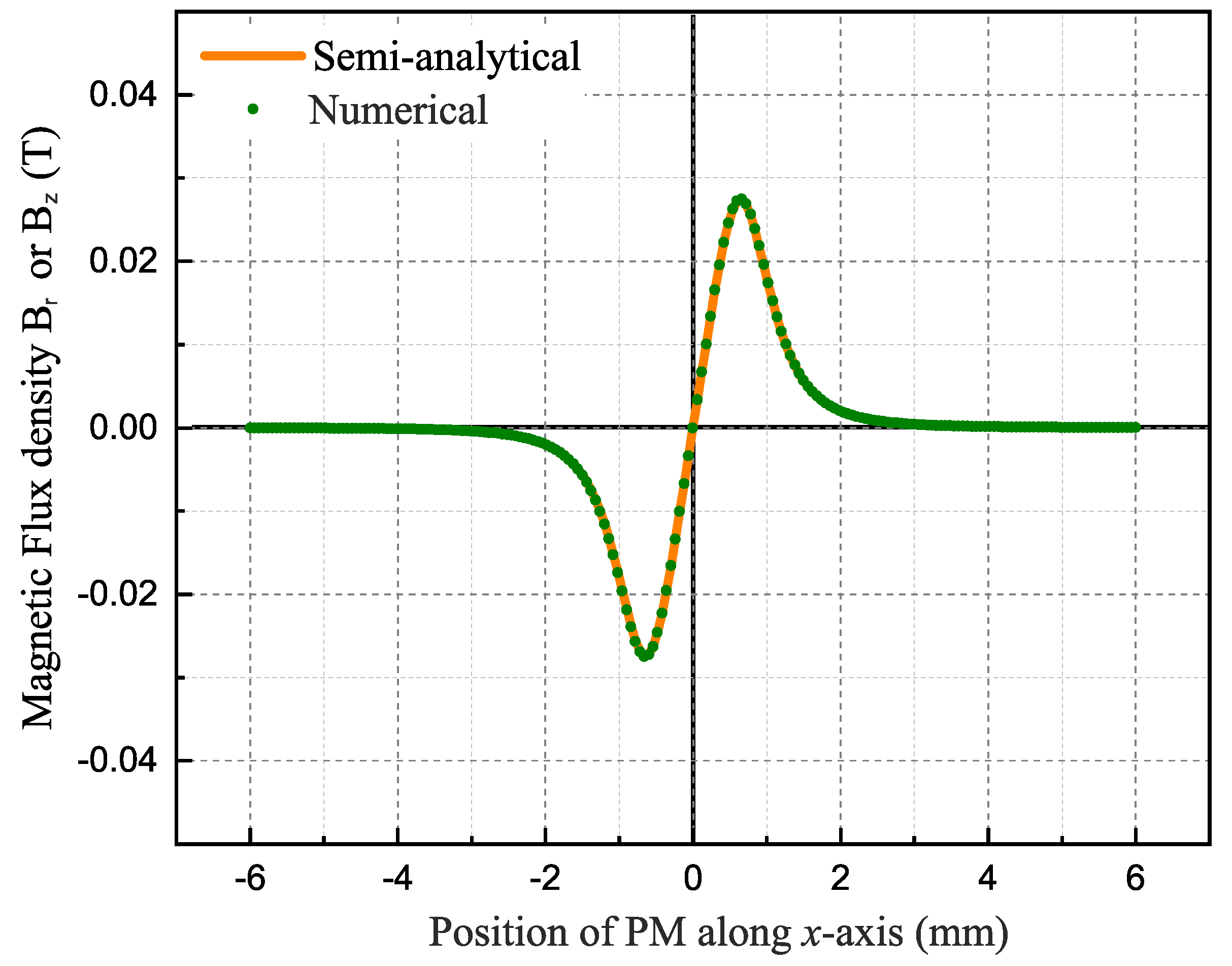
In order to design a prototype based on the presented principle, the magnetic and electromagnetic forces exerted on the MPM have to be computed. For that purpose, the magnetic flux density generated by the FPM and MPM were determined. Analytical equations were used to compute the magnetic flux density, and a comparison is provided with a semi-analytical model developed using the Radia software (Mathematica add-on). The FPM is cylindrical in shape, and Equation (1) was used to compute the magnetic flux density where and are the radial and axial magnetic flux components, R is the radius of the Permanent Magnet (PM), Ms is the magnetization, is the vacuum permeability, is the number of mesh points, is the integration coefficients, and is the value of the integrand evaluated for mesh points. A detailed description of this model was provided in [39,40].
Figure 3 represents the comparison of the magnetic flux density or between the numerical equations and the semi-analytical model developed with the Radia software for the considered cylindrical FPM. The magnetic flux density components were computed for different positions of the MPM along the x-axis. It can be observed from the figure that the two models gave very close results with a relative error of 10.
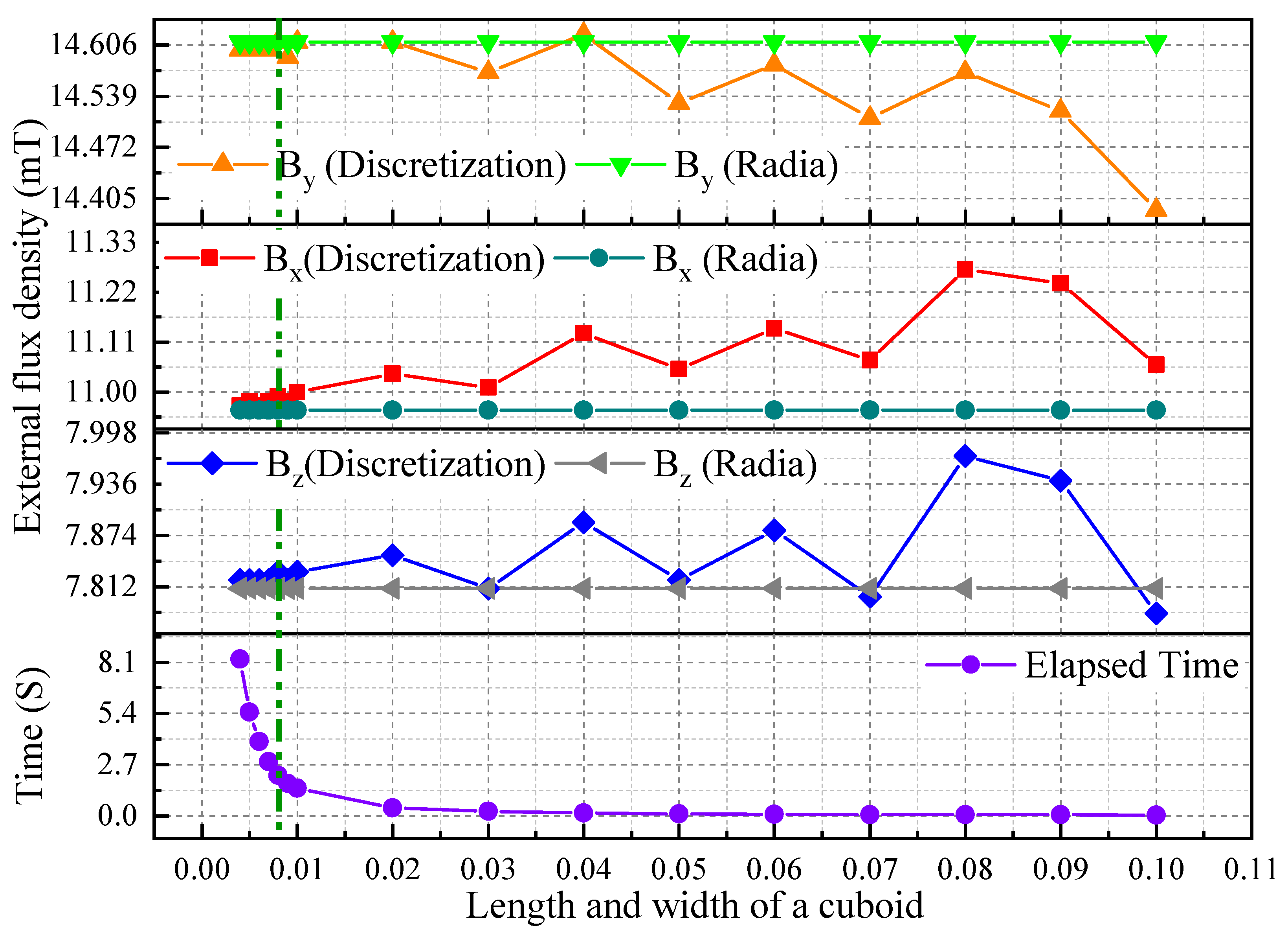
The MPM has a hexagonal section, and there is no analytical equation to compute the magnetic flux density for PMs with such a geometry. A discretization method was then used as reported in [41,42]. For that purpose, the volume of the considered hexagonal PM was discretized into n elementary cuboidal PMs in order to simplify the calculation, and the total magnetic flux density of the hexagonal PM was determined as the sum of the magnetic flux density generated by the n elementary cuboidal PMs. Elementary cuboidal PMs were considered in order to simplify the calculations. The magnetic flux density model () for cuboidal magnets is given by Equation (2) where (x2−x2), (y2−y1), (z2−z1) are the PMs dimensions, M is the magnetization, and is the vacuum permeability.
Figure 4 provides a comparison of the magnetic flux density generated by the MPM between the analytical calculation based on the discretization method and the semi-analytical model developed with the Radia software. The magnetic flux density components of the hexagonal MPM were computed for different lengths and widths of the elementary cuboidal PM used for discretization from 0.004 mm to 0.1 mm. The magnetic flux density was computed at a calculation point placed outside the MPM with coordinates (3 mm, 4 mm, 5 mm). It was observed that the error between the discretization method and the semi-analytical calculation was reduced when the size of the elementary cuboidal PM decreased. In addition, the calculation time for the discretization method is also given, and it can be observed that it strongly increased when the size of the elementary cuboidal PM decreased. Considering these results, a compromise was made between the calculation error and time by considering a cuboidal shape dimension of 0.008 mm × 0.008 mm × 0.008 mm. In this configuration, the obtained errors were 0.19%, 0.019%, and 0.08% for , respectively. These errors are very small and, therefore, neglected.
3.2. Force Calculation
The magnetic and electromagnetic forces exerted on the MPM were calculated using the presented magnetic flux density model. Equations (3) and (4) give the expressions of the magnetic and electromagnetic forces, respectively, where is the surface charge density, and are the external magnetic flux densities generated by the FPMs and the MPM, respectively, and I is the current in the electrical wire. The electromagnetic force exerted by the air core coil on the MPM was calculated using the semi-analytical software Radia.
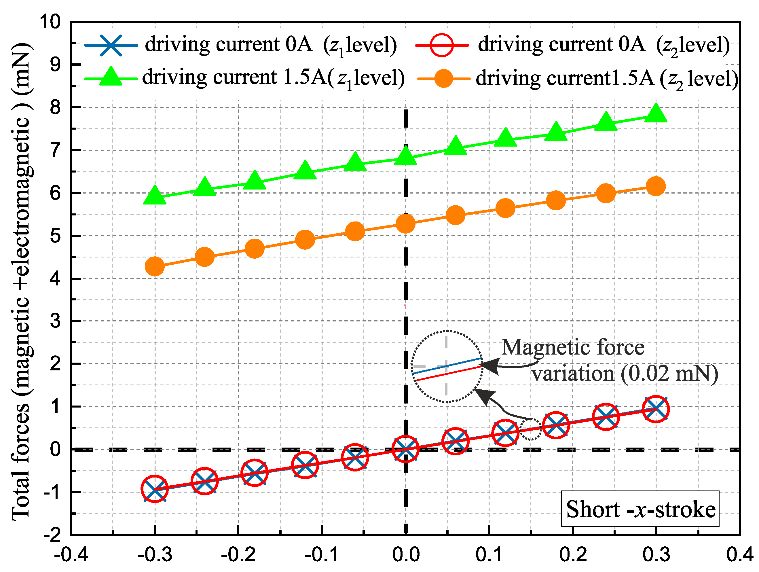
Figure 5 represents the total force (magnetic + electromagnetic) exerted on the MPM for different positions along the x-axis using the Short-x-stroke. The total force is indicated at both levels along the z-axis without a driving current (0 A) and with a 1.5 A driving current. Without a driving current, it can be observed that the magnetic force was almost linear because of the small stroke (0.6 mm) compared to the distance between the MPM and FPM (12.66 mm). A small magnetic force difference was observed between the z and z levels (0.02 mN), which was due to the variation of the relative position between the MPM and the FPM. Between the initial plot (0 A) and the one with 1.5 A, the added electromagnetic force can be observed (vertical shift). In addition, the electromagnetic force generated at the z level was lower than at z because the distance between the wires and the MPM was higher (+0.5 mm) when it was located at the z level compared to z.
The generated magnetic and electromagnetic forces exerted on the MPM when it was located in a discrete position are given in Table 2 for the four displacement strokes. As observed in Figure 5 for the Short-x-stroke, the difference in the magnetic forces between the two levels along the z-axis can also be seen for the y-Stroke (0.03 mN) and Long-x-stroke (0.04 mN). For the z-Stroke, the magnetic force was negligible when the MPM was located at the z level and maximum at the z level due to the relative position between the MPM and the FPMs. It can also be observed that the electromagnetic force along the y-axis was always lower compared to the x-axis due to the difference in the distance between the x-axis switching conductors and y-axis switching conductors (100 m) with respect to the MPM (as shown in Figure 1).
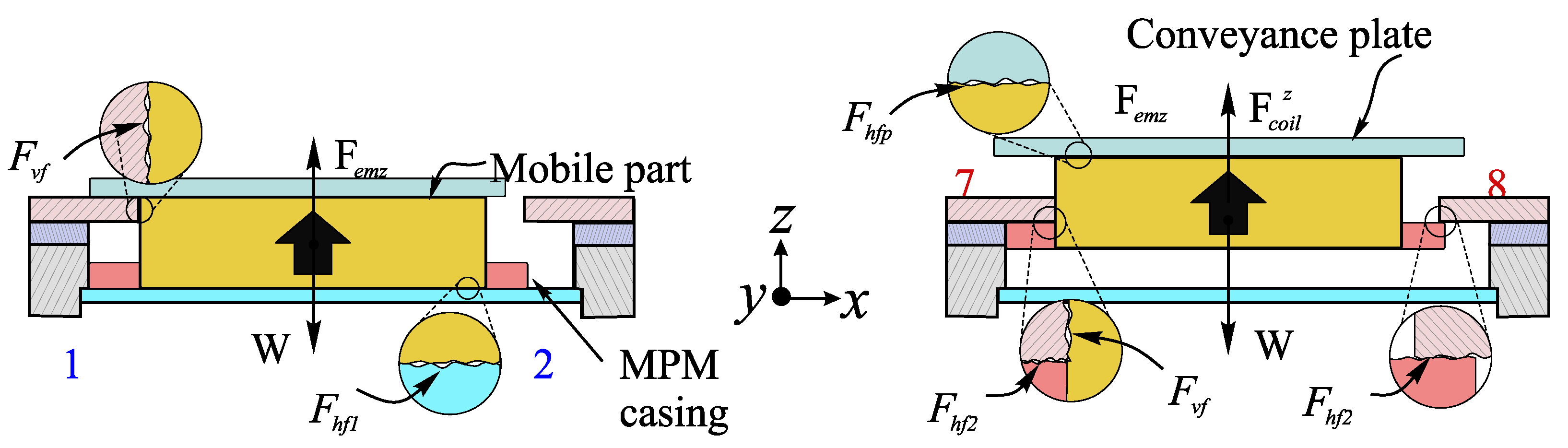
The frictional forces between the mobile and fixed parts of the system were also taken into account using a Coulomb model. There were in total four frictional forces to be considered, as shown in Figure 6. The and horizontal frictional forces characterize the contact between the bottom side of the MPM and the thin glass layer and the contact between the z-axis retainer and the top side of the cavity (Equation (5)), respectively. The contact between the lateral side of the MPM and the lateral side of the cavity is characterized by the vertical frictional force (Equation (6)). The characterizes the horizontal frictional force between the top side of the MPM and the mobile part (Equation (7)).
In Equations (5)–(7), W and are the weights of the mobile part (MPM + z-axis retainer) and of the mobile plate that were determined using a precise weighing machine and found to be 3.25 mN and 2.12 mN, respectively. is the vertical electromagnetic force exerted by the current-carrying conductors. is the electromagnetic force generated by the current-carrying air core coil at the z level. and are the horizontal and vertical frictional coefficients that were experimentally determined using an inclined plane technique and found to be 0.39 ± 0.06 and 0.48 ± 0.06, respectively. is the magnetic holding force generated by the FPMs on the MPM. This model was used to determine the different forces exerted on the different parts of the actuators and used to size them. Based on the design, a prototype was manufactured and is presented in the following section.
4. Experimental Setup and Results
4.1. Experimental Setup and Control Module
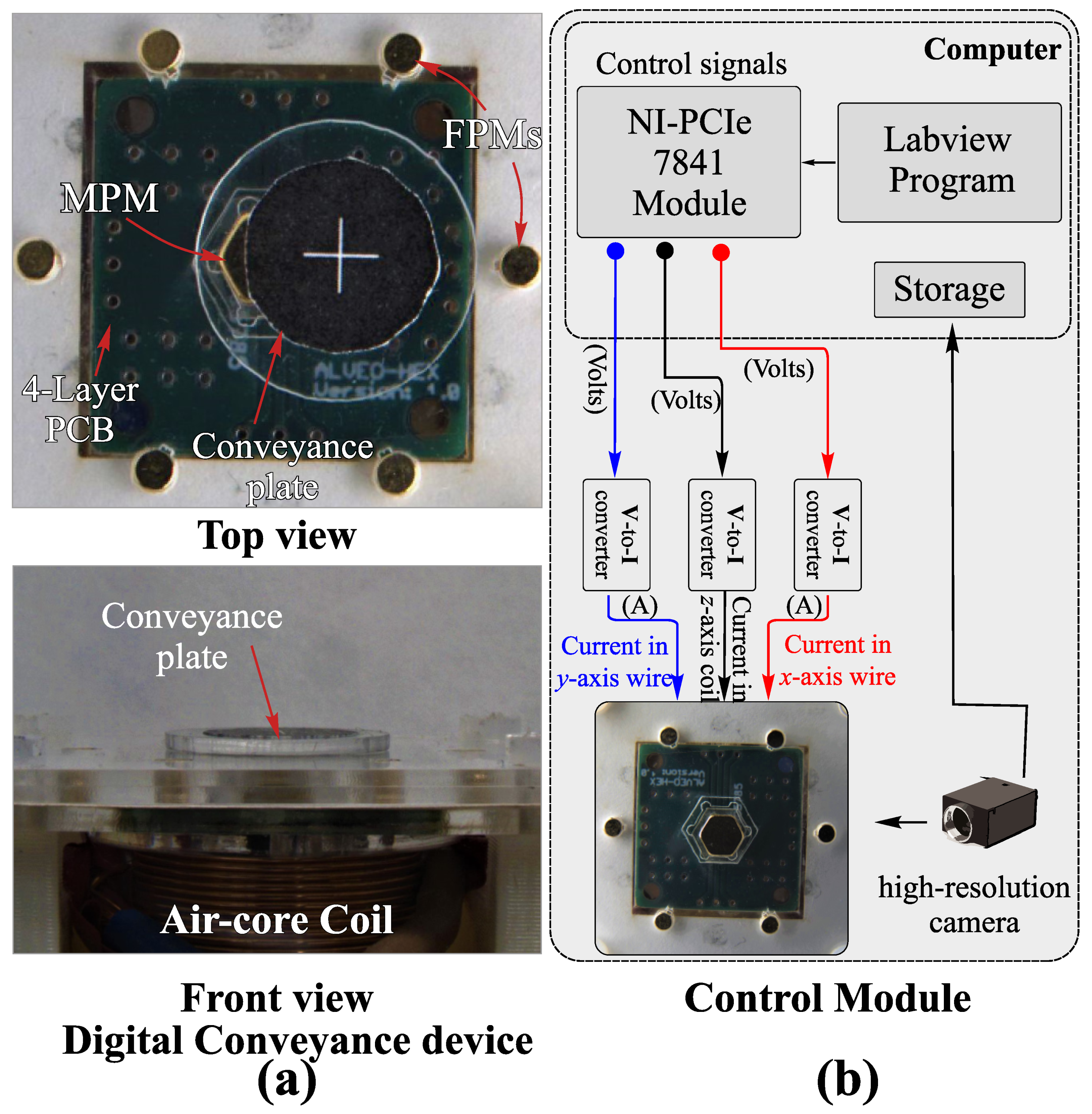
The developed prototype was composed of four main parts: a base support, a PCB support, and two plates with cylindrical and hexagonal cavities for the FPMs and the mobile part. The different parts were manufactured using the laser cutting technique, and the complete experimental assembly is shown in Figure 7.
The prototype was controlled via a data I/O module (National Instruments (NI)-PCIe 7841) and a LabView interface. Three voltage signals (one for each displacement axis) were generated and converted into current signals thanks to three voltage-to-current converters (V-I) (linear conversion, 50 kHz sampling rate (±10 V; ±7 A)). These current signals were then injected into the conductors for switching along the xy-axis and in the coil to switch along the z-axis. During the experimentation, a high-resolution camera (FLIR ORX-10G-51s5c-c) was used to observe and measure the plate displacement. Images from the camera were captured by a computer and analyzed using an image-processing program in order to determine the MPM and plate displacements. A calibration grid was used to calibrate the camera, and the pixel size of the acquired images was determined to be 0.69 m.
4.2. Results and Discussions
In this section, the experimental results are presented and discussed. Firstly, the experimental strokes of the actuator were measured with the help of a sticker with a “plus” sign placed on top of it (Figure 7a). Images were captured by the camera before and after the MPM switch, and the strokes were measured five times. The comparison between the theoretical and experimental strokes is provided in Table 3. It can be seen that the experimental stroke values were always higher than the theoretical ones. In the xy-plane, the minimum stroke error was obtained for the Long-x-stroke and the maximum error was obtained for Short-x-stroke. The differences between the theoretical and experimental stroke values were due to the manufacturing tolerances. The stroke error for the z-Stroke was the highest as it is linked to several parameters such as the variation in the thickness of the second plate, the geometry of the z-axis retainer, and its positioning on the MPM. The average difference of 36 m was due to the use of the laser cutting technique, which ensures maximum manufacturing tolerances of about 100 m. The stroke variation was homogeneous for the different directions, and the average stroke variation was lower than 4 m.
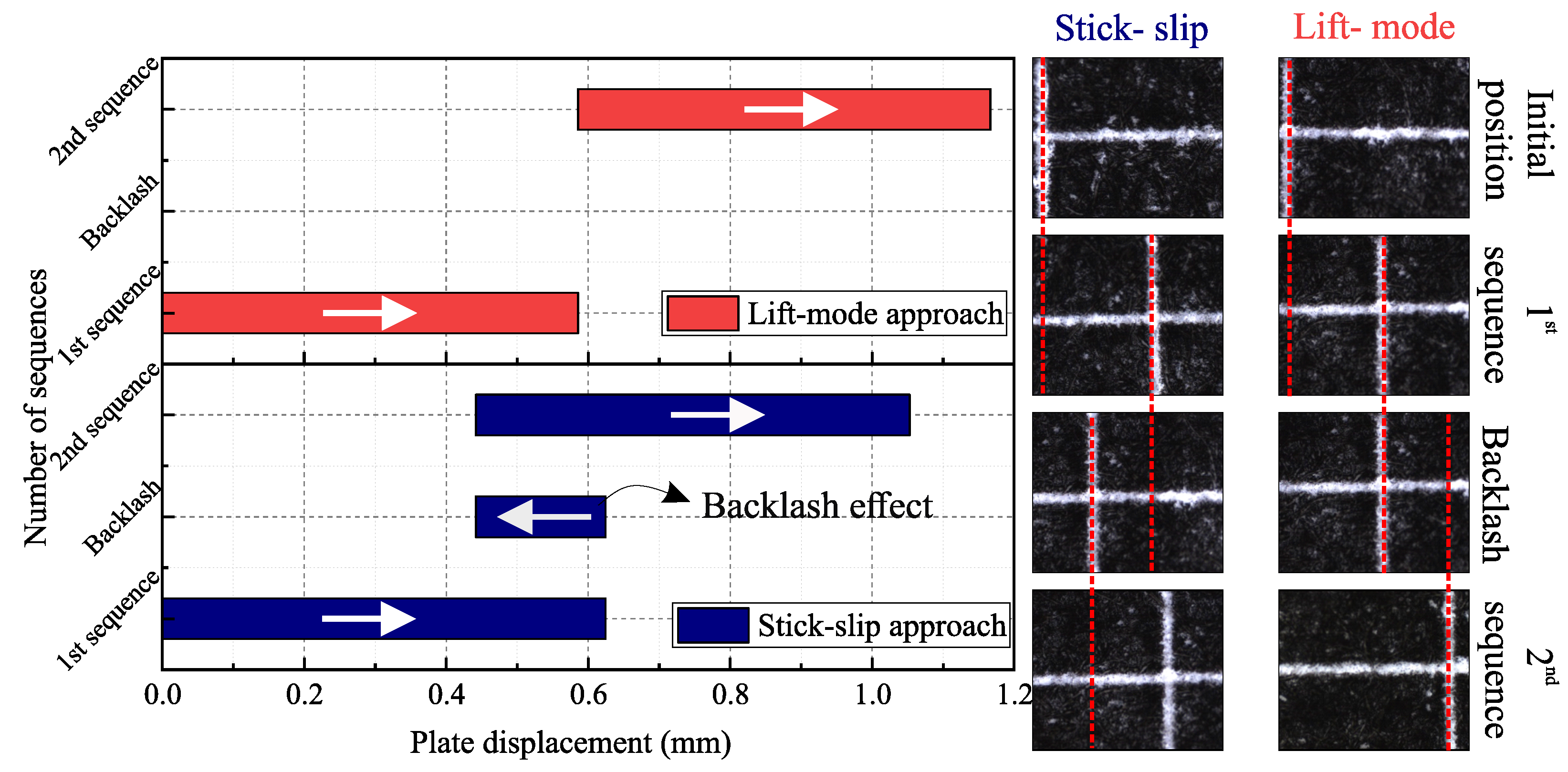
The two proposed approaches to move the plate were then tested using the Short-x-stroke. In order to measure the plate displacement, a similar method as the MPM stroke measurement was used with a sticker placed on top of the plate. Figure 8 represents the experimental plate displacement using both approaches for a 2 A driving current value. With the stick-slip approach, the return current was fixed at 7 A. Images of the initial plate position, after the first sequence, after the switching back of the MPM, and after the second sequence are shown. With the stick-slip approach, a backlash effect was indeed observed (0.17 mm) when the MPM was switched back to its initial position. This effect was of course not observed with the lift-mode approach. It can also be observed that the plate displacement in the first sequence was lower for the stick-slip approach (0.47 mm) compared to the lift-mode approach (0.58 mm). For the presented results, the plate displacement was obtained at the z level with the stick-slip approach, while the z level was used with the lift-mode approach. During this test, the time needed for one displacement sequence was approximately equivalent for both approaches and was 30 ms. For this experimental test, the motion speed could then be estimated to be between 15 mm·s and 19 mm·s for the stick-slip and lift-mode approaches, respectively.
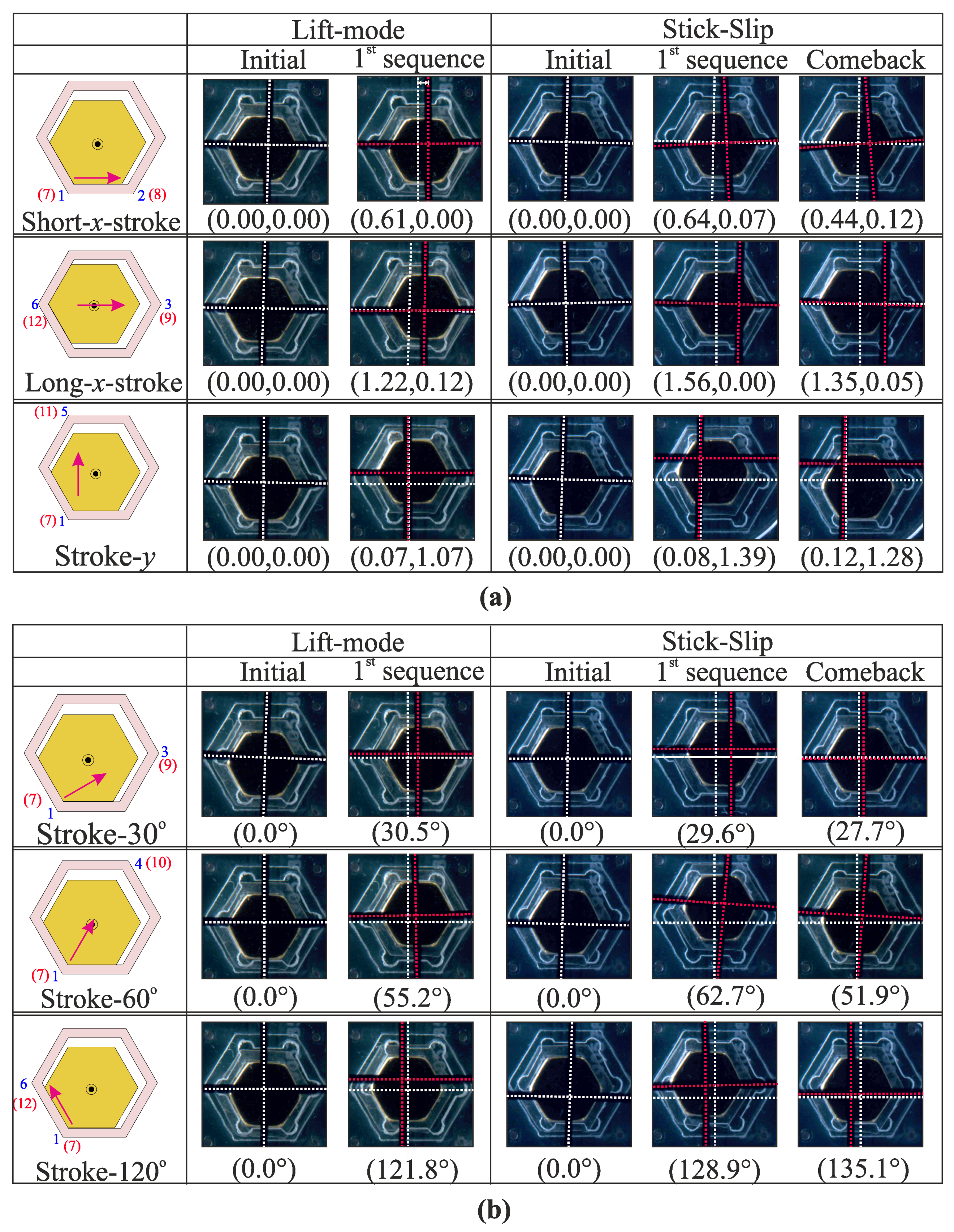
The proposed actuator was based on an hexagonal architecture whose main interest was to enable displacements in six directions. The ability to move the mobile plate in all these directions is shown in Figure 9 for both approaches. To clearly show the position of the MPM, as well as that of the moved object, a plus mark (without white background) was placed on top of the plate. Because the plate was composed of a glass layer, the MPM could also be observed. In the figure, the three displacement directions are shown (i.e., Short-x-stroke, Long-x-stroke, y-Stroke) and the three diagonal displacements (i.e., 30°, 60°, and 120°). For each displacement, the initial and final positions are shown, and for the stick-slip approach, the object position before the comeback step is also added. The white and red dashed lines represent the initial and final positions of the mobile plate, respectively, in order to clearly see the generated displacement. In these pictures, some errors can be observed as angle errors (due to small unexpected rotations of the plate) or straightness errors. These errors have several origins such as the friction inhomogeneity between the MPM and the plate and the manufacturing errors of the MPM and the cavity. In addition, the relative position between the plate and the mobile magnet also had an influence as the contact conditions depended on it. For the stick-slip approach, the backlash effect also introduced motion errors. In the future, several solutions will be investigated to minimize these errors, as described in the Conclusion Section. Based on the figure, it can be observed that the MPM was able to convey the mobile plate in the different directions provided by the hexagonal architecture.
The influence of the driving current value on the plate displacement was studied for different current values from 1.5 A to 7 A (Figure 10). For both approaches, the plate displacement was measured at the end of the displacement sequence (i.e., after the backlash effect for the stick-slip approach). The experiments were repeated five times, and the error bars correspond to the standard deviation on the measured points. It can be observed that as the current increased, there was a decrease in the plate displacement for both approaches. A current increase led indeed to a higher MPM acceleration, which resulted in an increase of the slipping effect between the plate and the MPM. In addition, it can be observed that the standard deviation gradually decreased as the current values increased. The plate motion was obtained thanks to the friction phenomenon between it and the MPM, and the origin of the observed standard deviation was mostly related to friction inhomogeneity. At low current, the influence of friction inhomogeneity was important compared to the electromagnetic force generated, and this influence reduced when the increase of the current.
The maximum displacement available with the prototype was determined for both approaches. Figure 11 shows the maximum object displacement using the Short-x-stroke and y-Stroke for a driving current of 2 A. Initially, the plate was placed at the center of the MPM, and then, several displacement sequences were realized until the MPM was not able to move the plate. Indeed, after a given number of sequences, the mobile plate went out of the limits due to its dimensions (15 mm), and it became impossible to move it back. The total obtained displacement was almost equal for both approaches, and after 13 displacement steps, the mobile part reached a strongly off-center position that prevented the MPM from moving it further. The same behavior was observed for displacement along the y-Stroke, and the maximum displacement was ±5.40 mm and ±7.05 mm for the Short-x-stroke and y-Stroke, respectively.
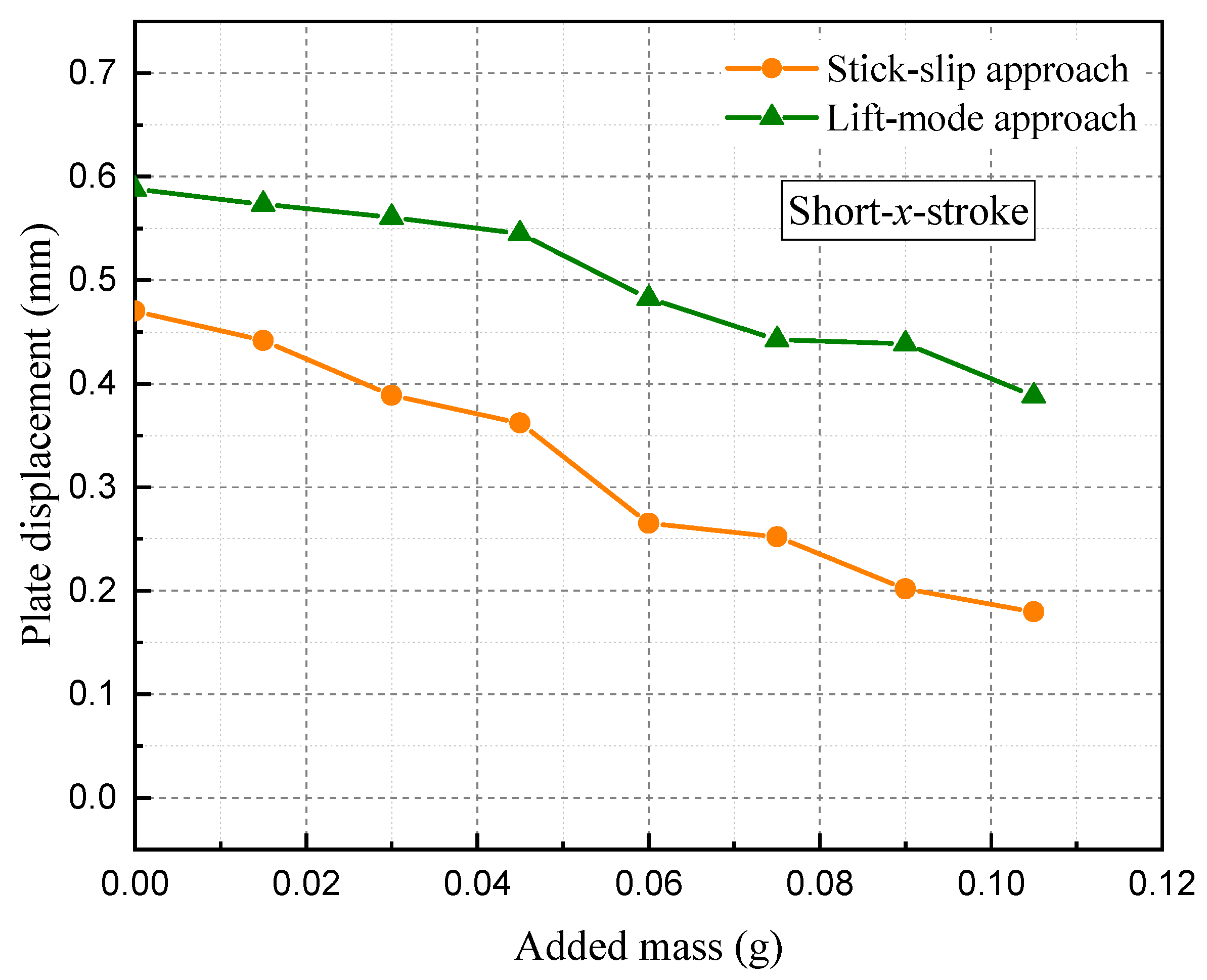
Because a displacement application was studied, the influence of the object mass on the generated displacement was also studied (Figure 12). For that, added pieces of glass (weighing 0.015 g each) were placed on the plate, and its displacement was measured for each configuration. The displacement was realized with the Short-x-stroke for both approaches and with a driving current of 2 A for the x-axis and 0.5 A for the z-axis (for lift-mode approach). From the figure, it can be observed that the obtained plate displacement was reduced when the mass was increased, and the displacement reduction was almost identical for both approaches. With the proposed actuator, a maximum mass of 1.15 g can be moved.
5. Conclusions
In this paper, a micro-positioning device based on a 3D hexagonal digital actuator was presented. The device is able to convey a part in the xy-plane using two different displacement approaches. One approach was based on a stick-slip principle, and the second used the vertical displacement axis to generate the motion. A model that considered the magnetic, electromagnetic, and friction forces was presented and used to design the device. A prototype was then realized and experimentally characterized. The experimental and theoretical stroke values were compared, and the average error was found to be 36 m. Its origin was the manufacturing tolerances of the laser cutting technique. The two positioning approaches were experimentally validated for displacements along each displacement direction provided by the hexagonal architecture of the actuator. The influence of the driving current on the object displacement was characterized, and displacement steps between 0.6 mm and 0.05 mm could be obtained. The positioning device stroke along the x- and y-axis was characterized and found to be ±5.40 mm and ±7.05 mm, respectively. Finally, the influence of the added mass on the displacement step was characterized, and the maximum mass that could be moved was found to be 1.15 g.
In the future, a new version of the device will be manufactured using micro-fabrication techniques in order to reduce the manufacturing errors. High-precision manufacturing will help to reduce the influence of the disruptions observed and then will contribute to improving the actuators’ performances. In addition, an array composed of several elementary tri-dimensional actuators will also be studied. With this array, the plate motion will be generated thanks to several actuators, which will reduce the influence of the relative position between the actuator and the plate. An actuator array will also enable more complex motions, long-range displacements using both approaches, and the motion of several objects simultaneously. Finally, an improvement of the device control will be studied. For that, a measurement of the plate position will be implemented in order to readjust from time to time the reached position and then compensate the motion errors.
Author Contributions
The authors contributed equally to this work. A.D. contributed to the development and prototyping of the mentioned actuator and was involved in the electronic system and writing of this article. L.P. also contributed to the design and prototyping; he also worked in the modeling of this actuator and also participated in the writing and review process. M.-u.K. was involved in the electronic circuits’ realization, the design, and the review of this article. F.L. contributed to the prototype characterization and the discussion for the future advancement of this project. C.P. contributed to the review process and supervision of this article. All authors have read and agreed to the published version of the manuscript.
Funding
This work was carried out under the ALVEO project, which was supported by the French National Research Agency (ANR) (Reference ANR-15-CE10-0002-01) and the European Regional Development Fund (ERDF).
Institutional Review Board Statement
Not applicable.
Informed Consent Statement
Not applicable.
Conflicts of Interest
The authors declare no conflict of interest.
Abbreviations
The following abbreviations are used in this manuscript:
| MPM | Mobile Permanent Magnet |
| FPM | Fixed Permanent Magnet |
| PCB | Printed Circuit Board |
| NI | National Instruments |
References
- Arora, N.; Khan, M.U.; Petit, L.; Lamarque, F.; Prelle, C. Design and Development of a Planar Electromagnetic Conveyor for the Microfactory. IEEE/ASME Trans. Mechatron. 2019, 24, 1723–1731. [Google Scholar] [CrossRef]
- Ding, B.; Yang, Z.X.; Xiao, X.; Zhang, G. Design of Reconfigurable Planar Micro-Positioning Stages Based on Function Modules. IEEE Access 2019, 7, 15102–15112. [Google Scholar] [CrossRef]
- Wang, T.; Li, Y.; Zhang, Y.; Lin, R.; Qian, J.; Dou, Z. Design of a flexure-based parallel XY micropositioning stage with millimeter workspace and high bandwidth. Sens. Actuators A Phys. 2021, 331, 112899. [Google Scholar] [CrossRef]
- Singh, Y.; Shah, S.P.; Gandhi, P.S. High resolution flexible 4-PPR U-base planar parallel microstage robotic manipulator. IOP Conf. Ser. Mater. Sci. Eng. 2018, 402, 012034. [Google Scholar] [CrossRef] [Green Version]
- Lv, X.; Wei, W.; Mao, X.; Chen, Y.; Yang, J.; Yang, F. A novel MEMS electromagnetic actuator with large displacement. Sens. Actuators A Phys. 2015, 221, 22–28. [Google Scholar] [CrossRef]
- Henriksson, J.; Gullo, M.; Brugger, J. Integrated long-range thermal bimorph actuators for parallelizable Bio-AFM applications. IEEE Sens. J. 2013, 13, 2849–2856. [Google Scholar] [CrossRef] [Green Version]
- Tellers, M.C.; Pulskamp, J.S.; Bedair, S.S.; Rudy, R.Q.; Kierzewski, I.M.; Polcawich, R.G.; Bergbreiter, S.E. Piezoelectric actuator array for motion-enabled reconfigurable RF circuits. In Proceedings of the 2015 Transducers—2015 18th International Conference on Solid-State Sensors, Actuators and Microsystems (TRANSDUCERS), Anchorage, AK, USA, 21–25 June 2015; pp. 819–822. [Google Scholar] [CrossRef]
- Skandani, A.A.; Chatterjee, S.; Smith, M.L.; Baranski, J.; Wang, D.H.; Tan, L.S.; White, T.J.; Shankar, M.R. Discrete-state photomechanical actuators. Extrem. Mech. Lett. 2016, 9, 45–54. [Google Scholar] [CrossRef] [Green Version]
- Okyay, A.; Erkorkmaz, K.; Khamesee, M.B. Mechatronic design, actuator optimization, and control of a long stroke linear nano-positioner. Precis. Eng. 2018, 52, 308–322. [Google Scholar] [CrossRef] [Green Version]
- Wang, R.; Zhang, X. A planar 3-DOF nanopositioning platform with large magnification. Precis. Eng. 2016, 46, 221–231. [Google Scholar] [CrossRef] [Green Version]
- Shi, Z.; Bélier, B.; Martincic, E.; Petit, L.; Moulin, J.; Lefeuvre, E.; Terrien, J.; Prelle, C.; Lamarque, F. Development of a 2D array of micromachined electromagnetic digital actuators for micro-conveyance applications. Microsyst. Technol. 2018, 24, 411–417. [Google Scholar] [CrossRef]
- Deshmukh, A.A.; Petit, L.; Khan, M.U.; Lamarque, F.; Prelle, C. A novel 3D electromagnetic digital actuator with 12 discrete positions. IEEE/ASME Trans. Mechatron. 2018, 23, 1653–1661. [Google Scholar] [CrossRef]
- Tisnés, S.D.; Petit, L.; Prelle, C.; Lamarque, F. Modeling and Experimental Validation of a Planar Microconveyor Based on a 2 x 2 Array of Digital Electromagnetic Actuators. IEEE/ASME Trans. Mechatron. 2021, 26, 1422–1432. [Google Scholar] [CrossRef]
- Roemer, D.B.; Bech, M.M.; Johansen, P.; Pedersen, H.C. Optimum Design of a Moving Coil Actuator for Fast-Switching Valves in Digital Hydraulic Pumps and Motors. IEEE/ASME Trans. Mechatron. 2015, 20, 2761–2770. [Google Scholar] [CrossRef]
- Chin, C.S.; Wheeler, C. Sliding-Mode Control of an Electromagnetic Actuated Conveyance System Using Contactless Sensing. IEEE Trans. Ind. Electron. 2013, 60, 5315–5324. [Google Scholar] [CrossRef]
- Russo, M.; Barrientos-Diez, J.; Axinte, D. A kinematic coupling mechanism with binary electromagnetic actuators for high-precision positioning. IEEE/ASME Trans. Mechatron. 2021, 1. [Google Scholar] [CrossRef]
- Zhi, C.; Shinshi, T.; Saito, M.; Kato, K. Planar-type micro-electromagnetic actuators using patterned thin film permanent magnets and mesh type coils. Sens. Actuators A Phys. 2014, 220, 365–372. [Google Scholar] [CrossRef]
- Li, X.; Zhao, Y.; Hu, T. Design of a novel electrothermal actuator for integrated MEMS safety-and-arming devices. In Proceedings of the 10th IEEE International Conference on Nano/Micro Engineered and Molecular Systems, Xi’an, China, 7–11 April 2015; pp. 63–66. [Google Scholar] [CrossRef]
- Thachil, G.; Nair, D.R.; DasGupta, A. Design and Fabrication of Reliable Power Efficient Bistable MEMS Switch Using Single Mask Process. J. Microelectromech. Syst. 2020, 29, 1225–1233. [Google Scholar] [CrossRef]
- Cao, Y.; Dong, J. High-performance low-voltage soft electrothermal actuator with directly printed micro-heater. Sens. Actuators A Phys. 2019, 297, 111546. [Google Scholar] [CrossRef]
- Zeng, Z.; Jin, H.; Zhang, L.; Zhang, H.; Chen, Z.; Gao, F.; Zhang, Z. Low-voltage and high-performance electrothermal actuator based on multi-walled carbon nanotube/polymer composites. Carbon 2015, 84, 327–334. [Google Scholar] [CrossRef]
- Ogden, S.; Jonsson, J.; Thornell, G.; Hjort, K. A latchable high-pressure thermohydraulic valve actuator. Sens. Actuators 2012, 188, 292–297. [Google Scholar] [CrossRef]
- Cheng, T.; He, M.; Li, H.; Lu, X.; Zhao, H.; Gao, H. A Novel Trapezoid-Type Stick Slip Piezoelectric Linear Actuator Using Right Circular Flexure Hinge Mechanism. IEEE Trans. Ind. Electron. 2017, 64, 5545–5552. [Google Scholar] [CrossRef]
- Wang, G.; Chen, G.; Zhou, H.; Bai, F. Modeling and tracking control for piezoelectric actuator based on a new asymmetric hysteresis model. IEEE/CAA J. Autom. Sin. 2017, 4, 782–791. [Google Scholar] [CrossRef]
- Wallenhauer, C.; Kappel, A.; Gottlieb, B.; Schwebel, T.; Lüth, T. Efficient class-B analog amplifier for a piezoelectric actuator drive. Mechatronics 2009, 19, 56–64. [Google Scholar] [CrossRef]
- Abadie, J.; Chaillet, N.; Lexcellent, C. Modeling of a new SMA micro-actuator for active endoscopy applications. Mechatronics 2009, 19, 437–442. [Google Scholar] [CrossRef] [Green Version]
- Wang, S.; Rong, W.; Wang, L.; Xie, H.; Sun, L.; Mills, J.K. A novel linear-rotary piezoelectric positioning stage based on surface’s rectangular trajectory driving. Precis. Eng. 2019, 55, 376–380. [Google Scholar] [CrossRef]
- Liu, Y.T.; Li, B.J. A 3-axis precision positioning device using PZT actuators with low interference motions. Precis. Eng. 2016, 46, 118–128. [Google Scholar] [CrossRef]
- Dao, D.V.; Pham, P.H.; Senkawa, S.; Sugiyama, S. Tangential and perpendicular driving micro transmission systems based on ratchet mechanism and electrostatic actuator. In Proceedings of the TRANSDUCERS 2009—2009 International Solid-State Sensors, Actuators and Microsystems Conference, Denver, CO, USA, 21–25 June 2009; pp. 45–48. [Google Scholar] [CrossRef]
- Schmitt, L.; Schmitt, P.; Hoffmann, M. 3-Bit Digital-to-Analog Converter with Mechanical Amplifier for Binary Encoded Large Displacements. Actuators 2021, 10, 182. [Google Scholar] [CrossRef]
- Fukuta, Y.; Chapuis, Y.A.; Mita, Y.; Fujita, H. Design, fabrication, and control of MEMS-based actuator arrays for air-flow distributed micromanipulation. J. Microelectromech. Syst. 2006, 15, 912–926. [Google Scholar] [CrossRef]
- Conrad, H.; Kaiser, B.; Gaudet, M.; Langa, S.; Stolz, M.; Uhlig, S.; Schimmanz, K.; Schenk, H. A Novel Electrostatic Actuator Class. Precis. Eng. 2016, 168, 1533–1536. [Google Scholar] [CrossRef]
- Li, G.Y.; Li, X.Y.; Wang, H.; Yang, Z.Q.; Yao, J.Y.; Ding, G.F. Fabrication and characterization of superhydrophobic surface by electroplating regular rough micro-structures of metal nickel. Microelectron. Eng. 2012, 95, 130–134. [Google Scholar] [CrossRef]
- Uranga, A.; Verd, J.; Marigó, E.; Giner, J.; Muñóz-Gamarra, J.; Barniol, N. Exploitation of non-linearities in CMOS-NEMS electrostatic resonators for mechanical memories. Sens. Actuators A Phys. 2013, 197, 88–95. [Google Scholar] [CrossRef]
- Deshmukh, A.; Petit, L.; Khan, M.U.; Lamarque, F.; Prelle, C. Development of a six positions digital electromagnetic actuator. In Proceedings of the 2017 IEEE International Conference on Advanced Intelligent Mechatronics (AIM), Munich, Germany, 3–7 July 2017; pp. 975–980. [Google Scholar] [CrossRef]
- Petit, L.; Hajjar, H.A.; Prelle, C.; Lamarque, F. Design, Modeling, and Characterization of an Optical Switch Based on Four Positions Digital Actuator. IEEE/ASME Trans. Mechatron. 2016, 21, 1518–1527. [Google Scholar] [CrossRef]
- Flader, I.B.; Chen, Y.; Shin, D.D.; Heinz, D.B.; Ortiz, L.C.; Alter, A.L.; Park, W.; Goodson, K.E.; Kenny, T.W. Micro-tethering for in-process stiction mitigation of highly compliant structures. In Proceedings of the 2017 IEEE 30th International Conference on Micro Electro Mechanical Systems (MEMS), Las Vegas, NV, USA, 22–26 January 2017; pp. 675–678. [Google Scholar] [CrossRef]
- Kumar, B.V.R.; Sivakumar, K.; Rao, Y.S.; Karunanidhi, S. Design of a New Electromagnetic Brake for Actuator Locking Mechanism in Aerospace Vehcile. IEEE Trans. Magn. 2017, 53, 8002606. [Google Scholar] [CrossRef]
- Furlani, E.P. Permanent Magnet and Electromechanical Devices; Furlani, E.P., Ed.; Academic Press: San Diego, CA, USA, 2001. [Google Scholar]
- Xu, F.; Lv, Y.; Xu, X.; Dinavahi, V. FPGA-Based real-time wrench model of direct current driven magnetic levitation actuator. IEEE Trans. Ind. Electron. 2018, 65, 9635–9645. [Google Scholar] [CrossRef]
- Reza, M.M.; Ahmad, A.; Kumar, P.; Srivastava, R.K. Semi-analytical model for triangular skewed permanent magnet axial flux machine. In Proceedings of the 2017 IEEE Transportation Electrification Conference (ITEC-India), Pune, India, 13–15 December 2017. [Google Scholar] [CrossRef]
- Rubeck, C.; Yonnet, J.P.; Allag, H.; Delinchant, B.; Chadebec, O. Analytical Calculation of Magnet Systems: Magnetic Field Created by Charged Triangles and Polyhedra. IEEE Trans. Magn. 2013, 49, 144–147. [Google Scholar] [CrossRef]
Figure 1.
Representation of (a) the micro-positioning device. (b) Different strokes at twelve discrete positions: (I) MPM located in position 1, (II) MPM located in position 6 and (III) MPM located in position 7. (c) Cross-sectional view of the digital actuator AA’.
Figure 1.
Representation of (a) the micro-positioning device. (b) Different strokes at twelve discrete positions: (I) MPM located in position 1, (II) MPM located in position 6 and (III) MPM located in position 7. (c) Cross-sectional view of the digital actuator AA’.

Figure 2.
Representation of the different approaches for conveyance: (a) Stick-slip approach. (b) Lift-mode approach.
Figure 2.
Representation of the different approaches for conveyance: (a) Stick-slip approach. (b) Lift-mode approach.

Figure 3.
Comparison of the magnetic flux density and between the semi-analytical and numerical models for a cylindrical PM.
Figure 3.
Comparison of the magnetic flux density and between the semi-analytical and numerical models for a cylindrical PM.

Figure 4.
Representation of total flux density model for a hexagonal magnet (the accepted configuration is represented using the green dotted line) and the elapsed time for calculation.
Figure 4.
Representation of total flux density model for a hexagonal magnet (the accepted configuration is represented using the green dotted line) and the elapsed time for calculation.

Figure 5.
Representation of the total force for the Short-x-stroke.

Figure 6.
Representation of the generated horizontal and vertical frictional forces for the MPM and the mobile plate.
Figure 6.
Representation of the generated horizontal and vertical frictional forces for the MPM and the mobile plate.

Figure 7.
(a) Experimental representation of the digital conveyance device. (b) Control module for the proposed device.
Figure 7.
(a) Experimental representation of the digital conveyance device. (b) Control module for the proposed device.

Figure 8.
Experimental representation of the stick-slip and lift-mode approaches for the Short-x-stroke.
Figure 8.
Experimental representation of the stick-slip and lift-mode approaches for the Short-x-stroke.

Figure 9.
Conveyance possibilities to all discrete positions with the help of the lift-mode and stick-slip approaches: (a) representation of the experimental stroke values for planar displacement; (b) representation of the angles obtained for angular displacement.
Figure 9.
Conveyance possibilities to all discrete positions with the help of the lift-mode and stick-slip approaches: (a) representation of the experimental stroke values for planar displacement; (b) representation of the angles obtained for angular displacement.

Figure 10.
Plate displacement with respect to the current for the stick-slip and lift-mode approaches.
Figure 10.
Plate displacement with respect to the current for the stick-slip and lift-mode approaches.

Figure 11.
Maximum possible sequences for the Short-x-stroke and y-Stroke with the stick-slip and lift-mode approaches before the plate goes out of the limits.
Figure 11.
Maximum possible sequences for the Short-x-stroke and y-Stroke with the stick-slip and lift-mode approaches before the plate goes out of the limits.

Figure 12.
Variation in the plate displacement with respect to the mass of the plate for both approaches.
Figure 12.
Variation in the plate displacement with respect to the mass of the plate for both approaches.


Table 1.
Dimensional and magnetic properties of the actuator.
| Permanent Magnets | ||
|---|---|---|
| MPM | FPM | |
| Shape | Hexagon | Cylinder |
| Dimensions | 5.5 mm (side) × 2 mm | Ø2.25 × 2 mm |
| Material | NdFeB | NdFeB |
| Magnetization | 1.40 T | 1.37 T |
| Mechanical structure and coil | ||
| Material | PMMA | |
| Top plate dimensions | 40 mm × 40 mm × 1 mm | |
| Second plate dimensions | 40 mm × 40 mm × 1 mm | |
| Coil | Ø 20 mm × 10 mm | |
| Ø 9 mm | ||
| Distances | ||
| FPM to cavity center | 12.88 mm | |
| x-switching wires to MPM | 0.2 mm | |
| y-switching wires to MPM | 0.3 mm | |
| Stroke values | ||
| Short-x-stroke | 0.6 mm | |
| Long-x-stroke | 1.20 mm | |
| y-Stroke | 1.04 mm | |
| z-Stroke | 0.5 mm | |
Table 2.
Magnetic and electromagnetic forces exerted on the MPM.
| Absolute Values of Magnetic Forces | ||||
|---|---|---|---|---|
| Short-x-Stroke | Long-x-Stroke | y-Stroke | z-Stroke | |
| z level | 0.95 mN | 1.91 mN | 1.64 mN | 0 mN |
| z level | 0.93 mN | 1.87 mN | 1.61 mN | 3.18 mN |
| Absolute Values of Electromagnetic Forces (For 1 A) | ||||
| Short-x-Stroke | Long-x-Stroke | y-Stroke | z-Stroke | |
| (F) | ||||
| z level | 4.58 mN | 4.58 mN | 4.27 mN | 0.72 mN |
| z level | 3.48 mN | 3.48 mN | 3.23 mN | 21.39 mN |
Table 3.
Comparison between the experimental and theoretical strokes.
| Displacement Directions | Theoretical Stroke (mm) | Experimental Stroke (mm) |
|---|---|---|
| Short-x-stroke | 0.600 | 0.635 ± 0.004 |
| Long-x-stroke | 1.200 | 1.216 ± 0.003 |
| y-Stroke | 1.040 | 1.072 ± 0.006 |
| z-Stroke | 0.500 | 0.545 ± 0.002 |
Publisher’s Note: MDPI stays neutral with regard to jurisdictional claims in published maps and institutional affiliations. |
© 2021 by the authors. Licensee MDPI, Basel, Switzerland. This article is an open access article distributed under the terms and conditions of the Creative Commons Attribution (CC BY) license (https://creativecommons.org/licenses/by/4.0/).
Share and Cite
MDPI and ACS Style
Deshmukh, A.; Petit, L.; Khan, M.-u.; Lamarque, F.; Prelle, C. Planar Micro-Positioning Device Based on a 3D Digital Electromagnetic Actuator. Actuators 2021, 10, 310. https://doi.org/10.3390/act10120310
AMA Style
Deshmukh A, Petit L, Khan M-u, Lamarque F, Prelle C. Planar Micro-Positioning Device Based on a 3D Digital Electromagnetic Actuator. Actuators. 2021; 10(12):310. https://doi.org/10.3390/act10120310
Chicago/Turabian StyleDeshmukh, Ajinkya, Laurent Petit, Muneeb-ullah Khan, Frédéric Lamarque, and Christine Prelle. 2021. "Planar Micro-Positioning Device Based on a 3D Digital Electromagnetic Actuator" Actuators 10, no. 12: 310. https://doi.org/10.3390/act10120310
Note that from the first issue of 2016, this journal uses article numbers instead of page numbers. See further details here.