Modeling and System Integration for a Thin Pneumatic Rubber 3-DOF Actuator


1
Department of Electrical and Electronic Engineering, Graduate School of Engineering, Tokyo University of Agriculture and Technology, 2-24-16 Nakacho, Koganei-shi, Tokyo 184-8588, Japan
2
Graduate School of Natural Science and Technology, Okayama University, 3-1-1 Tsushima-naka, Kita-ku, Okayama 700-8530, Japan
*
Author to whom correspondence should be addressed.
Actuators 2019, 8(2), 32; https://doi.org/10.3390/act8020032
Submission received: 14 February 2019
/
Revised: 10 April 2019
/
Accepted: 11 April 2019
/
Published: 16 April 2019
Abstract
:Recently, soft actuators have been getting increased attention within various fields. The actuators are composed of flexible materials and driven by pneumatic pressure. A thin pneumatic rubber actuator generating 3 degrees of freedom motion, called 3-DOF micro-hand, has small diameter McKibben artificial muscles which generate a contraction force in the axial direction. By this structure, the micro-hand contracts in the longitudinal direction and bends in any direction by changing the applied air pressure pattern to the artificial muscles. The input–output relation of the micro-hand, however, is complicated and has not been modeled. In this paper, modeling for 3-DOF micro-hand is proposed. Moreover, the experimental system is built for the micro-hand and the proposed model is evaluated by using the experimental results.
1. Introduction
Recently, Japan has been considered as having an aging population. Along with this, robots are expected to be used in various fields such as surgery in the medical field, human support in the welfare field and searching in the rescue field. In these fields, robots have to handle human bodies and objects carefully.
From these expectations, soft actuators have been getting increased attention for realizing such robots. Soft actuators are composed of flexible materials, for example, silicone rubber, synthetic resin, fiber reinforced rubber and so on. Therefore, soft actuators can handle human bodies and objects softly and be used in water or mud because of being rust-free. In addition, thanks to the structure, soft actuators can be made by low-cost, be small and simple. Various kinds of soft actuators have been researched and many of them are driven by pneumatic pressure. Pneumatic soft actuators mainly have a structure of tubes and balloons which show expanding and bending motions under air pressure. For example, there are McKibben pneumatic artificial muscle [1], a flexible micro actuator [2] and a miniature pneumatic bending rubber actuator [3,4,5].
The McKibben muscle was invented in the 1950s by Joseph L. McKibben to motorize pneumatic armorthotics to help control handicapped hands. The muscle is closed by two ends, one being the air input and the other the force attachment point. When pneumatic pressure is applied, the rubber tube of the muscle expands in the radial direction, and at the same time, contracts in the axial direction. As a result, contraction force in the axial direction is generated. However, the McKibben muscle can contract only in the axial direction. Bending motions are difficult.
To solve these problems, a thin pneumatic rubber 3-DOF actuator(hereinafter, referred to as 3-DOF micro-hand) is developed by S. Wakimoto [6].
The micro-hand has three McKibben pneumatic artificial muscles arranged in parallel. By this structure, the micro-hand can contract in the longitudinal direction and bend in any direction by changing input air pressure pattern to the muscles. Moreover, the micro-hand has a thin flat shape; therefore, it is expected to be used as a manipulator for small robots which can get in a narrow space or a robot for rehabilitation which supports human joints. On the other hand, the micro-hand has nonlineality by its materials and structures. Thus, the input–output relation of the micro-hand is complicated and has not been modeled. There are previous articles that modeled 3-DOF actuators [2,7], however, the actuators are different from 3-DOF micro-hand. A cross section of previous 3-DOF actuators is an equilateral triangle and previous 3-DOF actuators consist of three fiber-reinforced cylindrical rubber actuators. Fiber-reinforced cylindrical rubber actuator shows expanding motion under air pressure. In contrast, a cross section of 3-DOF micro-hand is an isosceles triangle and 3-DOF micro-hand consists of 3 McKibben artificial muscles. McKibben artificial muscle shows contracting motion under air pressure and is cheaper than a fiber-reinforced cylindrical rubber actuator. Therefore, production costs of 3-DOF micro-hand is thought to be cheaper than that of previous 3-DOF actuators. For these reasons, it is difficult to use previous models for a 3-DOF micro-hand.
In this paper, a model of a 3-DOF micro-hand is proposed when the micro-hand contracts in the longitudinal direction and bends in any direction by changing the applied air pressure pattern to the artificial muscles. Moreover, the experimental system of the micro-hand is built and the proposed model is compared with the experimental results.
2. Materials and Methods
This section describes methods for deriving model of a 3-DOF micro-hand. First, the structure of the micro-hand is introduced. Then, the model of McKibben pneumatic artificial muscles is explained as a preparation for deriving a model of the micro-hand. Finally, the model of the micro-hand is made by dividing the bending micro-hand in the axial direction and obtaining the coordinates of the micro-hand from the divided piece. The piece consists of three cylinders which have different axial lengths and diameters. By considering the piece, model of the micro-hand is proposed. Comparing the proposed model with an actual measurement is made by simulation using MATLAB(R2016a), which is one of the effective software products for system engineering. Results of simulation are shown in the next section. Each subsection below shows detailed information about the structure and modeling for the micro-hand.
2.1. The Structure of the 3-DOF Micro-Hand
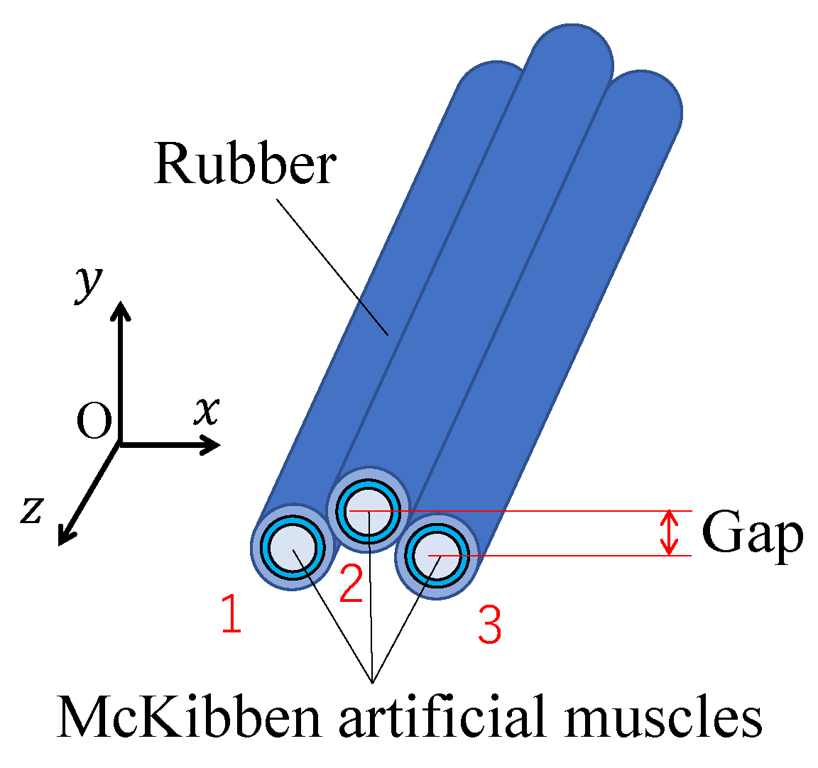
3-DOF micro-hand has three McKibben pneumatic artificial muscles arranged in parallel. Three muscles are covered and bonded with silicone rubber. Figure 1 shows the structure of the micro-hand. These muscles are not arranged in a single line, and the center muscle is raised above the other muscles as shown in Figure 1. By this gap, bending motion in the y direction can be achieved [6].
The x, y and z axes and muscles 1, 2 and 3 are defined as shown in Figure 1. x axis is in the direction of width, y axis is the direction of thickness and z axis is longitudinal direction. The sequence of the muscle 1, 2 and 3 follows x axis.
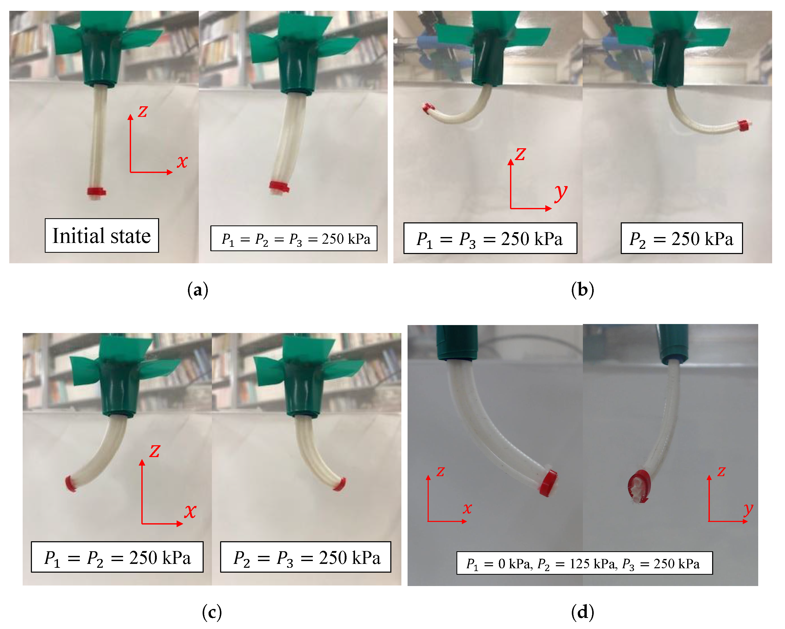
The micro-hand can contract in the longitudinal direction and bend in any direction by changing an input air pressure pattern to the muscles. Figure 2a shows the contracting motion toward z direction. The micro-hand contracts in the longitudinal direction by applying same pneumatic pressure to all muscles. Moreover, Figure 2b shows the bending motions in the positive and negative y directions. It can bend towards positive and negative y directions by applying air pressure to muscle 2 and muscles 1 and 3, respectively. Figure 2c shows the bending motions in the positive and negative x directions. It can bend towards positive and negative x directions by applying air pressure to muscles 2 and 3 and muscles 1 and 2, respectively. By applying pneumatic pressure with more complicated pattern, the micro-hand can bend in any direction. Figure 2d shows bending motion when and .
2.2. Modeling
2.2.1. Model of McKibben Pneumatic Artificial Muscle
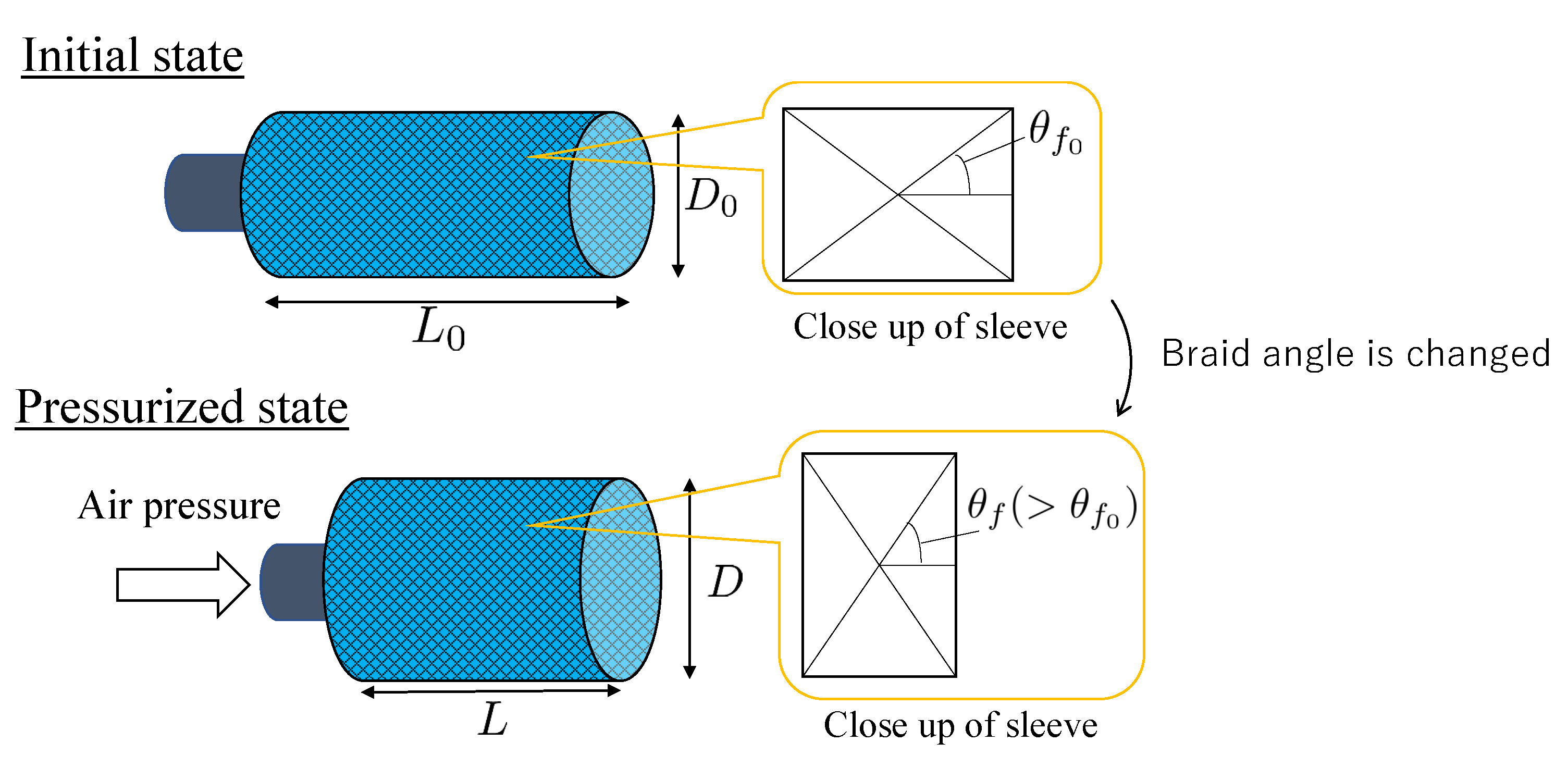
The model of McKibben pneumatic artificial muscle is described before the model of 3-DOF micro-hand is derived. Figure 3 shows the structure of the McKibben pneumatic artificial muscle. When pneumatic pressure is applied, the rubber tube expands in the radial direction, and at the same time, the fibers forming the sleeve work as a pantograph mechanism with changing the braid angle. As a result, contraction force F is generated and the muscle contracts in the axial direction [8]. In this paper, it is supposed that the fibers forming a mesh sleeve do not deform elastically. During contraction, the briad angle of the muscle, initially equal to , becomes and the muscle radius, initially equal to , becomes . Thereby, its axial length, initially equal to , becomes L.
Contraction force model [8] represents a relation between F, input pressure P and contraction ratio as
where is represented as:
Equation (4) is based on the hypothesis of a continuously cylindrical-shaped muscle, whereas the muscle takes a conic shape at both ends when it contracts [9]. It generates a difference between the model and the actual phenomenon. To deal with this problem, correction factors , are considered by T. Itto [10]. In this work, and are derived by comparing simulation results with experimental results. The correction factors amplify the contraction ratio . The modified force model [10] is
From Equation (7), the relation between input pressure and the axial length of the muscle i () is obtained by:
From Equation (3), the relation between input pressure and the radial length of the muscle i is obtained by:
2.2.2. Model of 3-DOF Micro-Hand
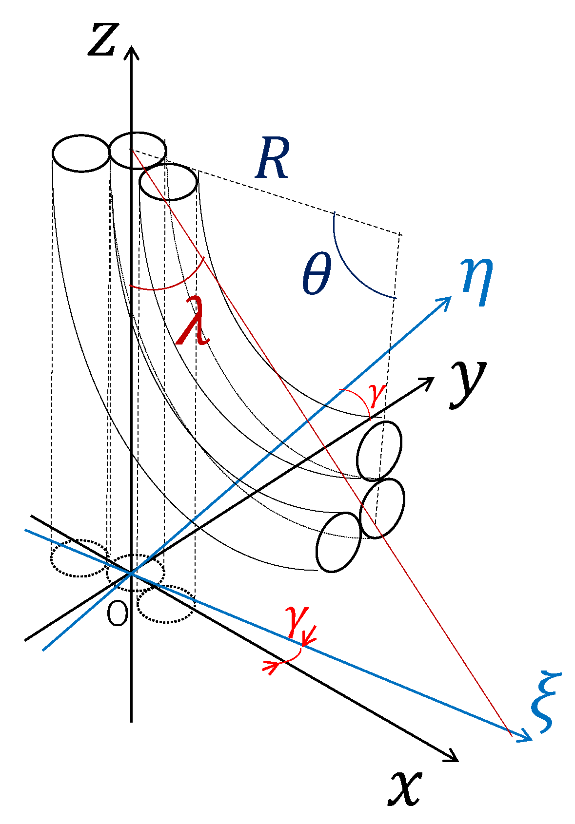
Figure 4 is model of 3-DOF micro-hand which is used by deriving the coordinates of the tip of the micro-hand when air pressure is applied. In this paper, it is supposed that the micro-hand curves in arc and does not expand in the axial direction. The coordinate system is an orthogonal coordinate system. The origin of the system is the center of gravity of a triangle having vertices which are the centers of the apical surfaces of the muscles in the initial state. The micro-hand is arranged symmetrically to the -plane.
-axis coincides with the central axis of the bending micro-hand mapped on -plane. The z coordinate system is formed by the coordinate system which is rotated on z-axis.
is an angle between x-axis and -axis(hereinafter, referred to as bending direction angle), R is a curvature radius of the central axis of the micro-hand, is bending angle of the micro-hand and is an angle between z-axis and a straight line passing through the tip and the bottom of the micro-hand. It is necessary to represent R, and as a function of inner pressures , and to the muscle 1, 2 and 3 for control. In the following section, the methods are described.
2.2.3. Relation between Input Pressure and Output Angle
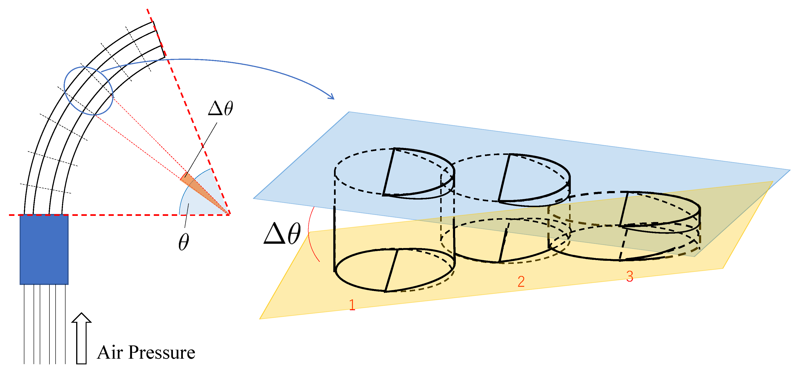
In this section, a method for deriving bending angle and bending direction angle is described. These angles are derived by using vectors. First, a method for deriving is described. The micro-hand is divided into n pieces equally in axial direction and a piece of the divided micro-hand is discussed for deriving . Figure 5 shows a piece of the divided micro-hand. The piece consists of three cylinders which have different axial lengths and diameters. The centers of the axial length of three cylinders are on the same plane. A plane including 3 centers of the tops of cylinders and a plane including 3 centers of the bottoms of cylinders are considered. are derived from an angle formed by 2 planes. is formulated as multiplication of n and .
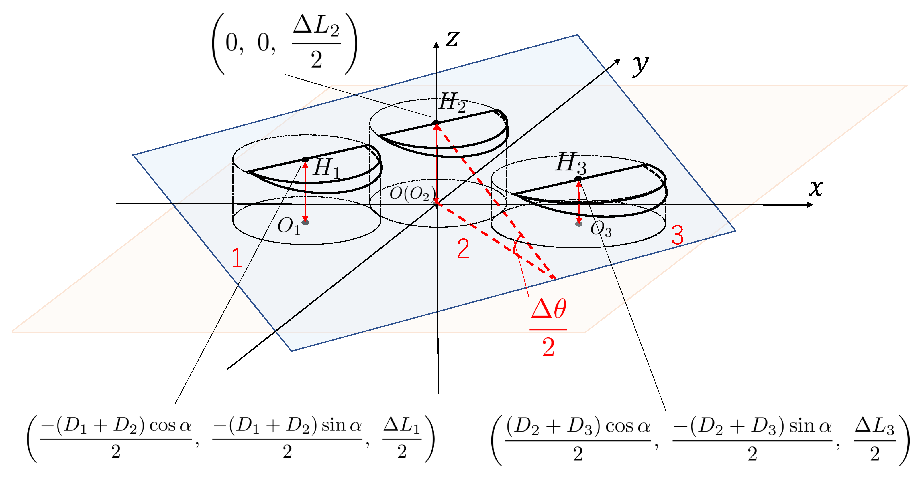
The piece in Figure 5 is divided into 2 pieces equally in axial direction once more. Figure 6 shows a solid figure of the piece generated from the piece in Figure 5. The bottoms of three cylinders in Figure 6 are on the same plane(xy-plane). The coordinate origin of the coordinate system is defined as the center of the bottom of the muscle 2. , and are defined as the center of the bottom of the muscle 1, 2 and 3, respectively. The coordinates are (, , 0), (), (, , 0), respectively. , and are defined as the center of the top of the muscle 1, 2 and 3, respectively. The coordinates are (, , ), (0, 0, ), (, , ), respectively. The axial lengths of the muscle 1, 2 and 3 of the piece show , and , respectively. and () are equal to Equations (8) and (9), respectively. is an angle between segment () and x-axis in initial state. In this paper, it is supposed that is constant if the input pressure P changes. is shown as:
where is the initial diameter of the muscle and d is the initial gap between muscle 2 and muscle 1(3) in y-axis direction.
An angle between a plane including , , and a plane including , , (-plane) is defined as .
is designated as a normal vector of a plane including , and . and are in a plane including , and .
n1 is obtained from calculating an outer product of and . Moreover, each component of n1 in Equation (13) is designated as a, b, and c, respectively.
is designated as a normal vector of a plane including , and (-plane).
is obtained from calculating an inner product of and .
In the left side of Equation (16), approximations are made by using Taylor expansion, because is an enough small value.
is formulated as multiplication of n and .
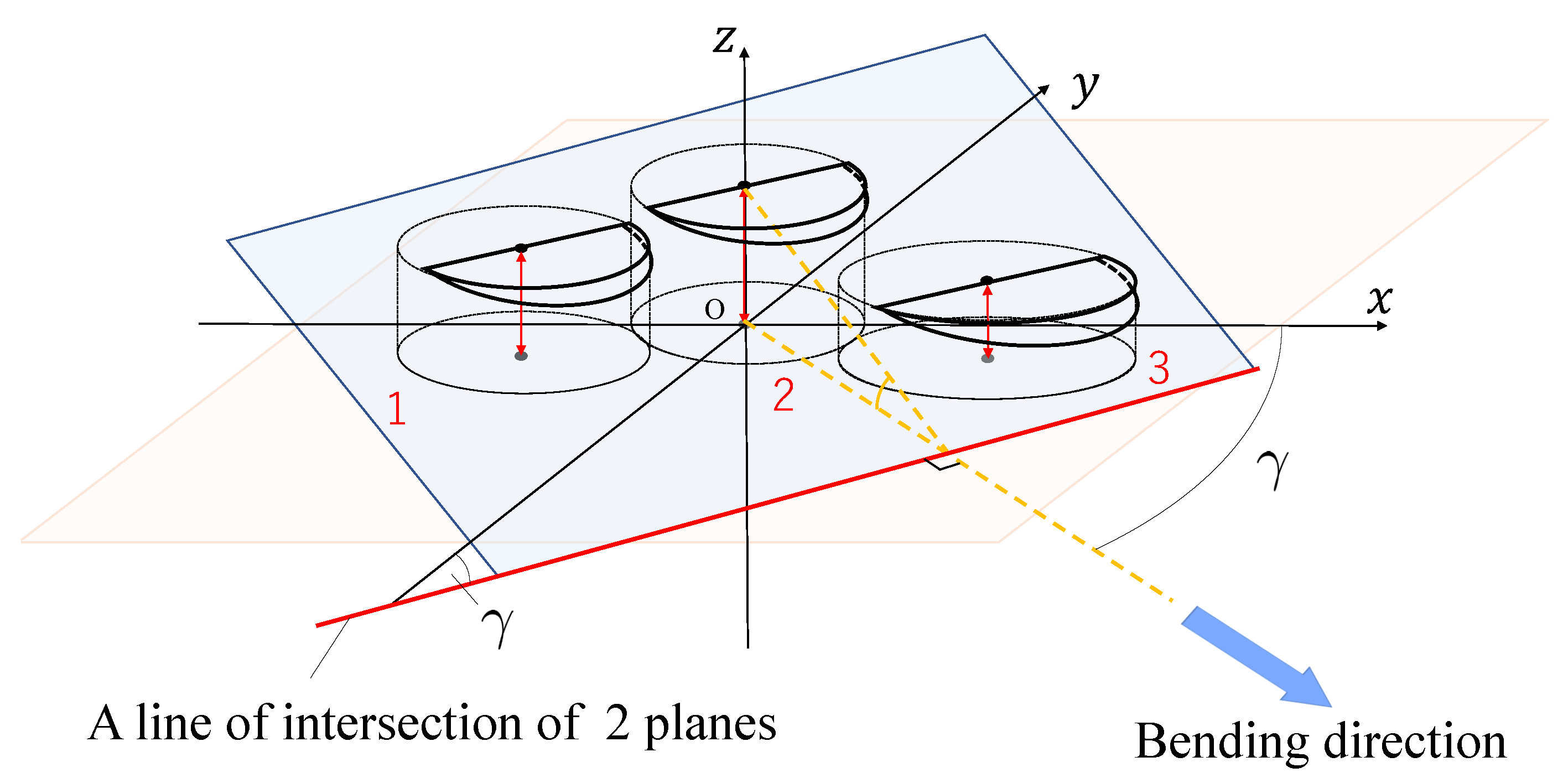
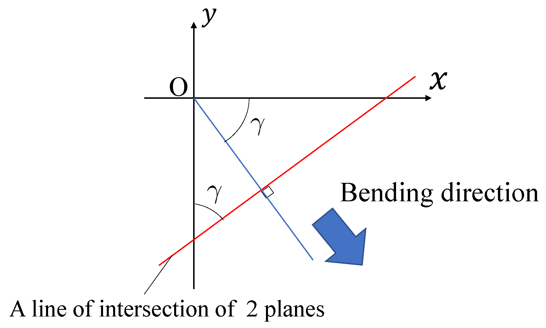
From Figure 7 and Figure 8, bending direction angle is an angle between y-axis and a line of intersection of a plane including , , and a plane including , , (-plane).
is designated as a vector of a line of intersection of a plane including , and and a plane including , and (-plane). From calculating an outer product of and , is obtained by:
From calculating the inner product of and y-axial vector, an angle between and y-axis is shown as:
2.2.4. Geometric Transformation into the Coordinate System
The coordinates of the tip of the micro-hand at the time of deformation is determined by R, and . From Figure 4, R, and are replaced with x, y and z geometrically.
where R and are shown as Equations (25) and (26), respectively [7].
Exceptionally, if , the micro-hand does not bend, thus and do not exist. The micro-hand contracts in the axial direction. If , the coordinates of the tip of the micro-hand are obtained by:
3. Results
3.1. Experiment
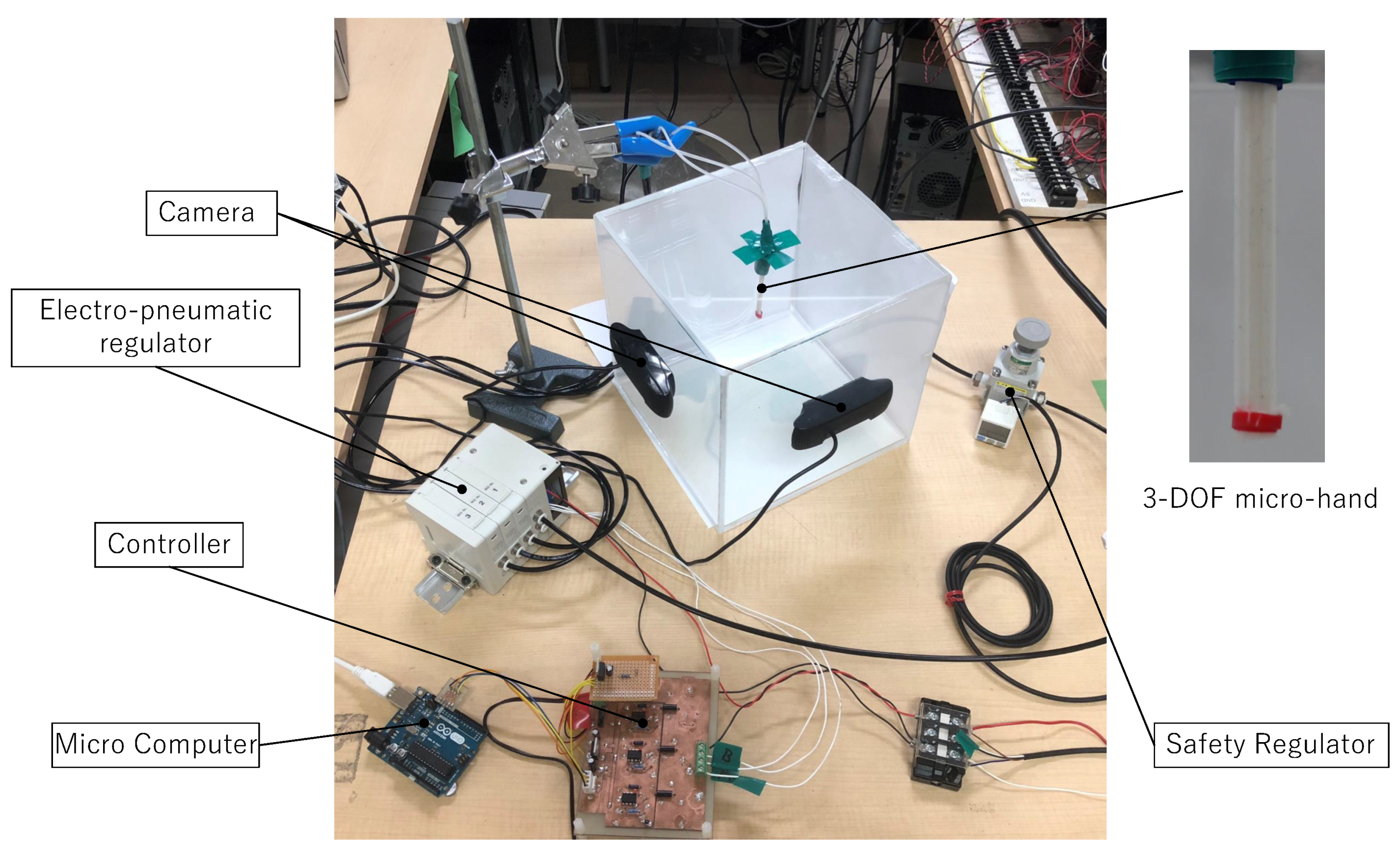
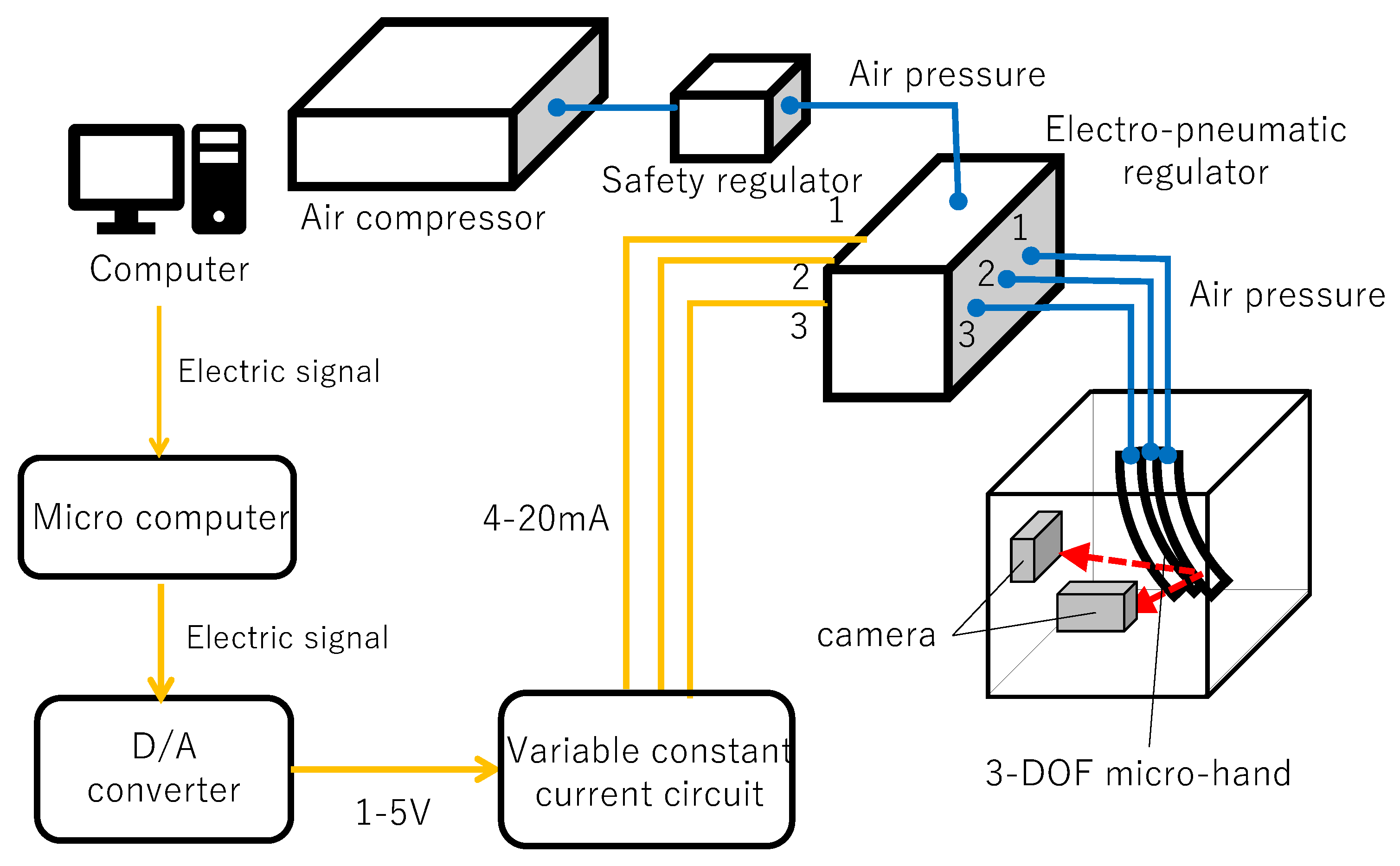
Experimental system is shown in Figure 9 and experimental setup in Figure 10. An experimental system is configured by 3-DOF micro-hand, an air compressor(0.20P-5S, HITACHI, Tokyo, Japan), a safety regulator(RP1000-8-07, CKD, Aichi, Japan), an electro-pneumatic regulator(MEVT500, CKD, Aichi, Japan) providing different pressures for the muscles, a controller for an electro-pneumatic regulator, a computer sending electrical signal and two cam eras(HD Pro Webcam C920r, Logicool, Tokyo, Japan) measuring outputs of the micro-hand. The following explains how to move the micro-hand.
- The air compressor provides an air pressure for the safety regulator.
- The safety regulator converts the pressure to at most for not breaking the micro-hand.
- The computer sends electrical signal to the controller for the electro-pneumatic regulator.
- The controller provides 4 mA–20 mA for the electro-pneumatic regulator and decides the opening of the electro-pneumatic regulator.
- Desired pressures are sent into the muscles of the micro-hand respectively and the micro-hand bends or contracts.
Outputs are captured as image by two cameras. The tip of the micro-hand is wrapped in a red tape. The following is an algorithm which specifies -coordinates of the tip of the micro-hand.
- Obtain a color image captured by two cameras and convert into a gray scale.
- Dissolve the image into 3 pixel numbers; R, B, G.
- Extract only R pixels from the image in comparison with a gray scale.
- Obtain the center coordinate from extracted R pixel area.
3.2. Experimental Result
Experimental results are obtained by using cameras and rulers. Experiments with camera are conducted five times. Comparing the simulation results with the experimental results is made by simulation using MATLAB(R2016a).
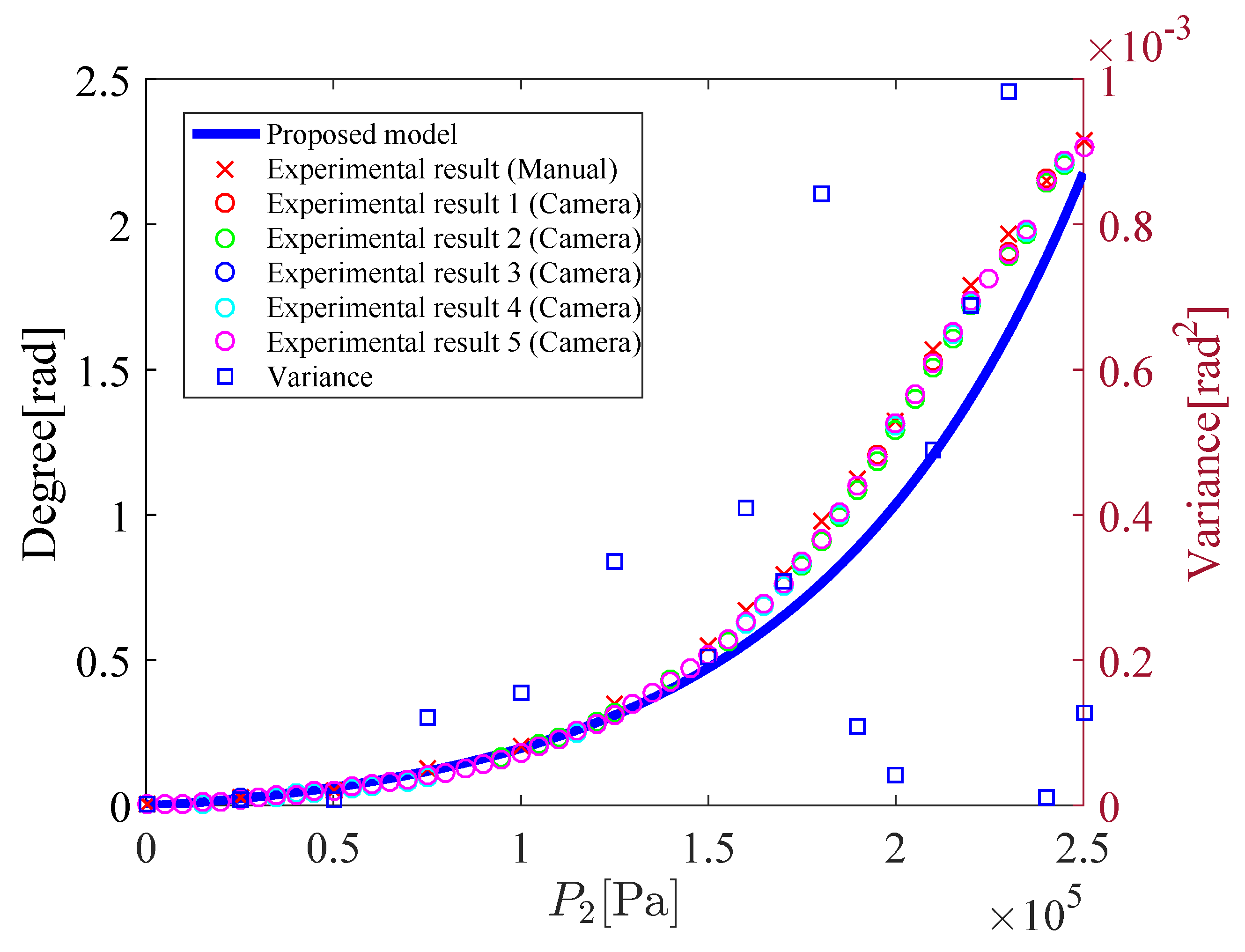
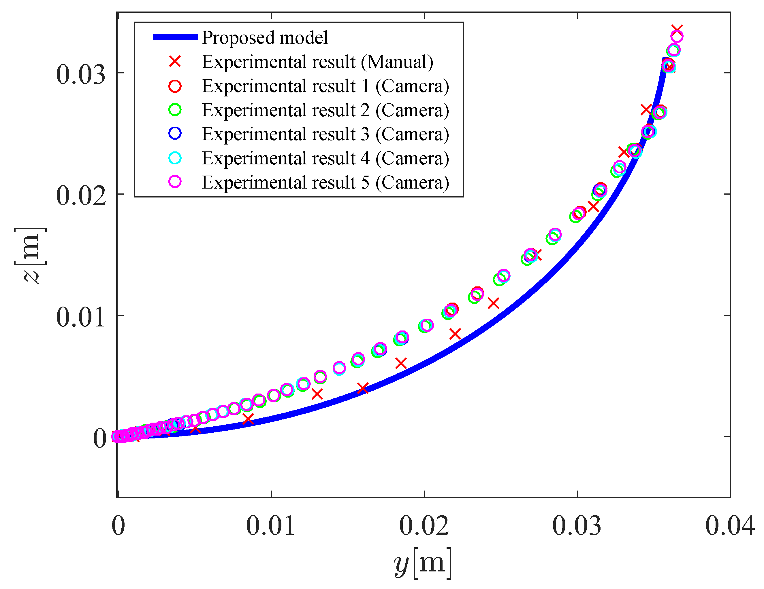
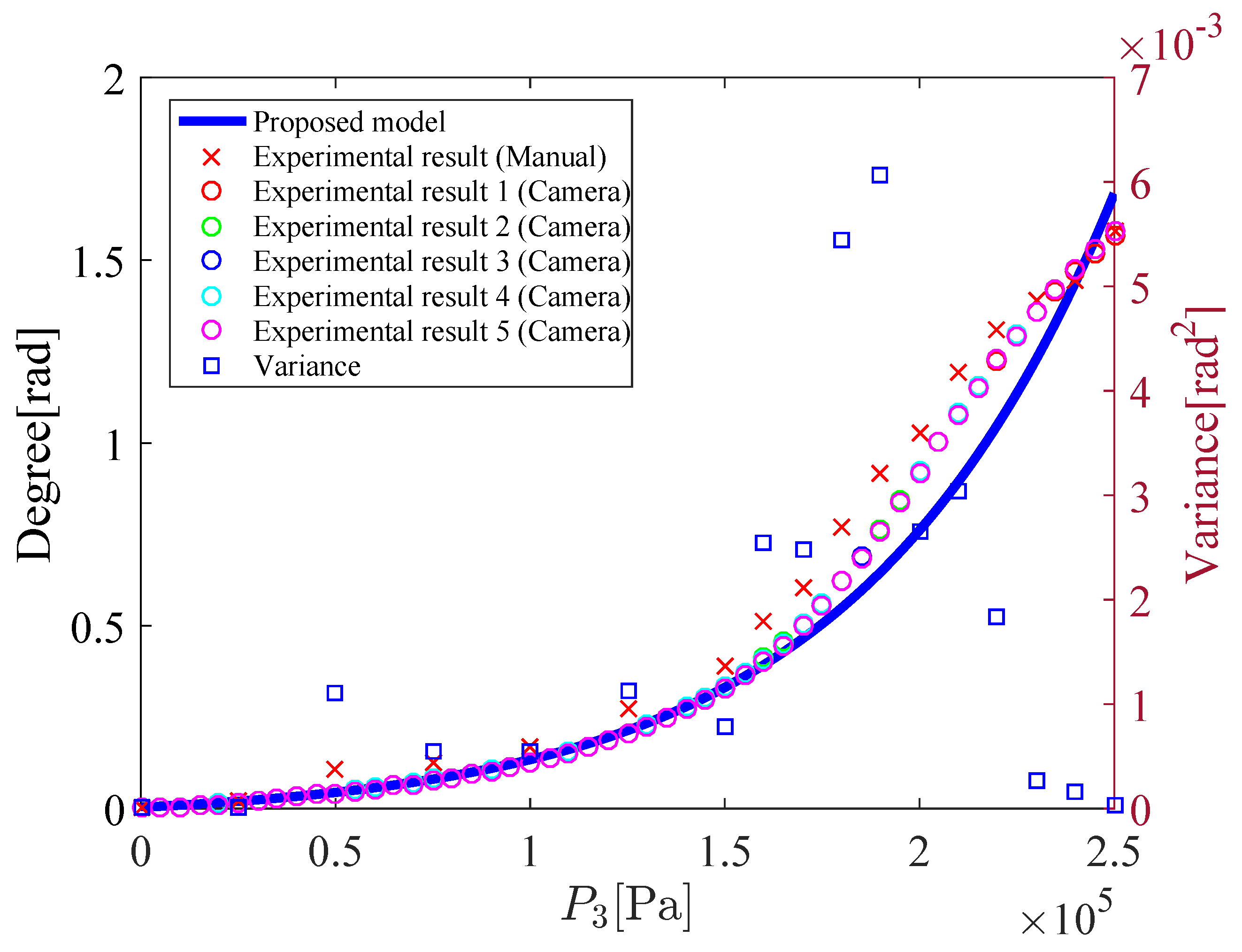
Figure 11 shows the relation between the input pressure and the bending angle . Figure 12 shows the coordinates of the tip of the micro-hand. In Figure 11 and Figure 12, and is increased from to . When and 0 kPa–250 kPa, the tip of the micro-hand curves on the -plane and the displacement of the x-axis direction is rather smaller than the displacement of the y-axis direction. Therefore, only the coordinate of the tip of the micro-hand on the -plane is shown in Figure 12.
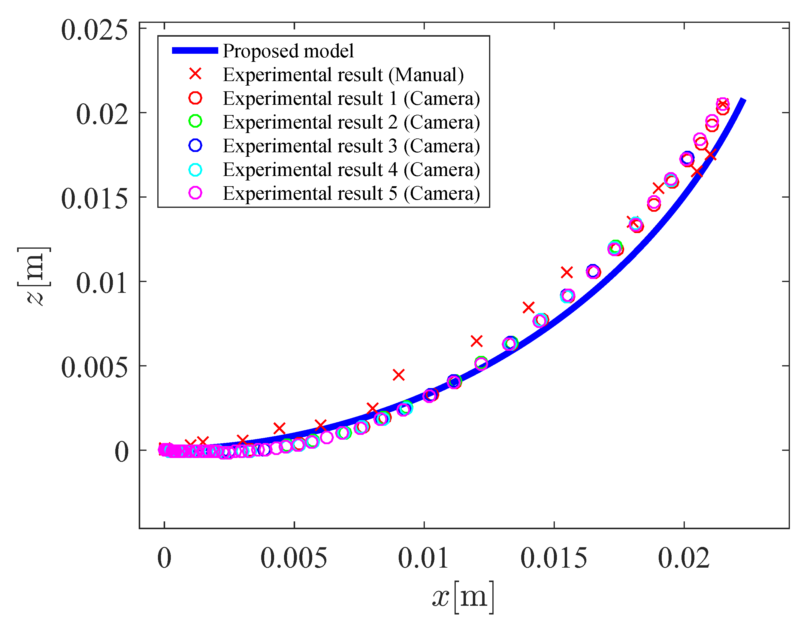
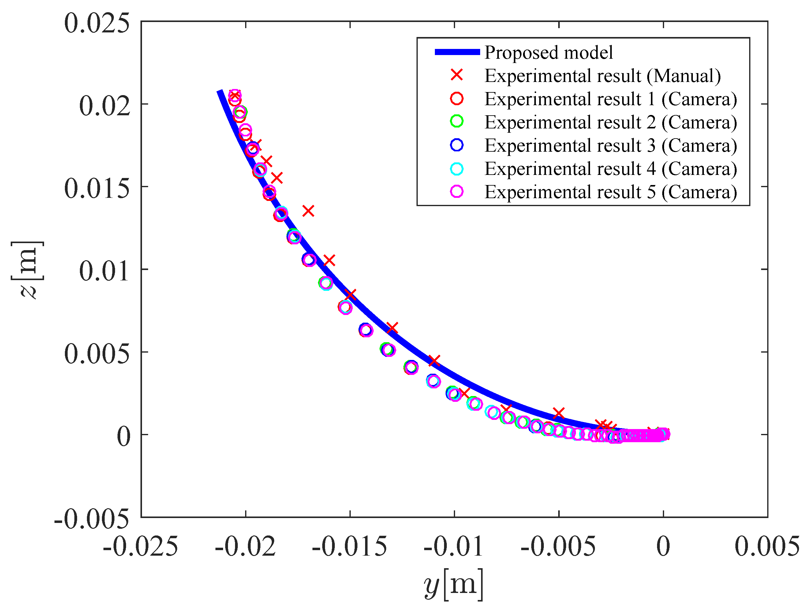
Figure 13 shows the relation between the input pressure and the bending angle . Figure 14 and Figure 15 shows the coordinates of the tip of the micro-hand. In Figure 13, Figure 14 and Figure 15, and is increased from to . Table 1 shows the parameters of the proposed model. However, the x-coordinate and the bending direction angle have a difference between the proposed model and the experimental results. To deal with this problem, correction factors , are considered, which amplify the x-coordinate and the bending direction angle. Previous models without using correction factors [2,7] were derived by a concept of a beam of strength which is one of the bending actions in mechanics of material. In previous models, force which a chamber applies to the next chamber is considered, however, there were computational complexities. Therefore, the correction factors are used to simplify the model for 3-DOF micro-hand. and are decided by comparing the proposed model with the experimental results. The modified x and are represented as Equations (32) and (33), respectively.
To compare the experimental results obtained by cameras with those obtained by rulers, variance of the measurements is calculated. The variance is plotted in Figure 11 and Figure 13. The variance in Figure 11 and Figure 13 is small, therefore, the effectiveness of the experimental results obtained by cameras is shown. As can be shown in Figure 11, Figure 12, Figure 13, Figure 14 and Figure 15, results of the proposed model are close to the experimental results. For comparing simulation results with experimental results measured by cameras, mean absolute percentage error(MAPE) is calculated. From Figure 12, MAPE is 5.5% when , 0 kPa–250 kPa. From Figure 14 and Figure 15, MAPE is 4.1% when , 0 kPa–250 kPa. Therefore, the effectiveness of the proposed model is shown. It is considered that the difference between the proposed model and the experiment is caused by the supposition that the micro-hand curves in arc and does not expand in the axial direction.
4. Conclusions
In this paper, a model of 3-DOF micro-hand is made. There had not been enough experimental results to verify the effectiveness of the proposed model, therefore the experimental system is built and experimental results are obtained. Finally, the proposed model dynamics is compared with the experimental results and the effectiveness of the proposed model is shown. The model of the micro-hand, however, needs to be improved, since the model needs the correction factors and the factors are decided by comparing the simulation results with the experimental results. In the model, 3-DOF micro-hand curves in an arc and does not expand in the axial direction. In addition, the model is derived mathematically and geometrically. Therefore, force which a muscle applies to the next muscle is not considered. This causes the difference between the model and the experimental results. By considering these problems, the model is thought to be improved. In addition, a control system of the micro-hand has not been designed. Future work should include these problems.
Author Contributions
S.K. modelled and integrated the experiment system for the actuator and wrote the paper; M.S. integrated the experiment system for the actuator. M.D. suggested technical support and gave overall guidance on the paper; Y.N. suggested technical support and advised the experimental set-up; S.W. developed the actuator and advised the experimental set-up.
Funding
This research received no external funding.
Conflicts of Interest
The authors declare no conflict of interest.
Abbreviations
The following abbreviations are used in this manuscript:
| DOF | Degrees of freedom |
References
- Chou, C.P.; Hannaford, B. Measurement and modeling of McKibben pneumatic artificial muscles. IEEE Trans. Robot. Autom. 1996, 12, 90–102. [Google Scholar] [CrossRef] [Green Version]
- Suzumori, K. Flexible Microactuator: 1st Report, static characteristics of 3 DOF actuator. Trans. Jpn. Soc. Mech. Eng. C 1989, 55, 2547–2552. (In Japanese) [Google Scholar] [CrossRef]
- Wakimoto, S.; Suzumori, K.; Ogura, K. Miniature pneumatic curling rubber actuator generating bidirectional motion with one air-supply tube. Adv. Robot. 2011, 25, 1311–1330. [Google Scholar] [CrossRef]
- Sudani, M.; Deng, M.; Wakimoto, S. Modeling and operator-based nonlinear control for a miniature pneumatic bending rubber actuator considering bellows. Actuators 2018, 7, 26. [Google Scholar] [CrossRef]
- Fujita, K.; Deng, M.; Wakimoto, S. A miniature bending rubber controlled by using the PSO-SVR-based motion estimation method with the generalized gaussian kernel. Actuators 2017, 6, 6. [Google Scholar] [CrossRef]
- Toyama, Y.; Wakimoto, S. Development of a thin pneumatic rubber actuator generating 3-DOF motion. In Proceedings of the 2016 IEEE International Conference on Robotics and Biomimetics, Qingdao, China, 3–7 December 2016; Volume 12, pp. 1215–1220. [Google Scholar]
- Kimura, Y.; Nishikawa, A. Study of the extension type 3-degrees-of-freedom bending model using a pneumatic soft actuator: Derivation of the theoretical formula of fiber-reinforced cylindrical rubber actuators and evaluation of their static properties. In Proceedings of the 2015 JSME Conference on Robotics and Mechatronics, Kyoto, Japan, 17–19 May 2015; pp. 1P1-T01(1)–1P1-T01(4). (In Japanese). [Google Scholar]
- Nozaki, T.; Noritsugu, T. Motion analysis of McKibben type pneumatic rubber artificial muscle with finite element method. Int. J. Autom. Technol. 2014, 8, 147–158. [Google Scholar] [CrossRef]
- Tondu, B.; Lopez, P. Modeling and Control of McKibben artificial muscle Robot Actuators. IEEE Control Syst. Mag. 2000, 20, 15–38. [Google Scholar]
- Itto, T.; Kogiso, K. Hybrid modeling of mckibben pneumatic artificial muscle systems. In Proceedings of the Joint IEEE International Conference on Industrial Technology Southeasetern Symposium on System Theory, Auburn, AL, USA, 14–16 March 2011; Volume 3, pp. 65–70. [Google Scholar]
Figure 1.
The structure of 3-DOF micro-hand.

Figure 2.
(a) Contracting motion toward z direction. (b) Bending motions in the y directions. (c) Bending motions in the x directions. (d) Bending motion when and .
Figure 2.
(a) Contracting motion toward z direction. (b) Bending motions in the y directions. (c) Bending motions in the x directions. (d) Bending motion when and .

Figure 3.
The structure of McKibben artificial muscle.

Figure 4.
The model for analysis.

Figure 5.
A piece of the divided micro-hand.

Figure 6.
Divided bending angle .

Figure 7.
Bending direction angle.

Figure 8.
Bending direction angle(-plane).

Figure 9.
Experimental system.

Figure 10.
Experimental setup.

Figure 11.
Bending angle (, 0–250 kPa).

Figure 12.
The coordinate values y and z of the tip of the micro-hand (, 0 kPa–250 kPa).

Figure 13.
Bending angle (, 0 kPa–250 kPa).

Figure 14.
The coordinate values x and z of the tip of the micro-hand (, 0 kPa–250 kPa).

Figure 15.
The coordinate values y and z of the tip of the micro-hand (, 0 kPa–250 kPa).


Table 1.
Parameters of the proposed model.
| Parameter | Definition | Value |
|---|---|---|
| Initial length of the micro-hand | ||
| Initial radius of the muscle | ||
| Initial braid angle | ||
| d | Gap between muscle 2 and 1(3) | |
| n | Number of divided micro-hand | 100 |
| Correction factor 1 of muscle 1 | 500 | |
| Correction factor 2 of muscle 1 | ||
| Correction factor 1 of muscle 2 | 530 | |
| Correction factor 2 of muscle 2 | ||
| Correction factor 1 of muscle 3 | 500 | |
| Correction factor 2 of muscle 3 | ||
| Correction factor of x-coordinate | ||
| Correction factor of bending direction angle |
© 2019 by the authors. Licensee MDPI, Basel, Switzerland. This article is an open access article distributed under the terms and conditions of the Creative Commons Attribution (CC BY) license (http://creativecommons.org/licenses/by/4.0/).
Share and Cite
MDPI and ACS Style
Kawamura, S.; Sudani, M.; Deng, M.; Noge, Y.; Wakimoto, S. Modeling and System Integration for a Thin Pneumatic Rubber 3-DOF Actuator. Actuators 2019, 8, 32. https://doi.org/10.3390/act8020032
AMA Style
Kawamura S, Sudani M, Deng M, Noge Y, Wakimoto S. Modeling and System Integration for a Thin Pneumatic Rubber 3-DOF Actuator. Actuators. 2019; 8(2):32. https://doi.org/10.3390/act8020032
Chicago/Turabian StyleKawamura, Shuhei, Mizuki Sudani, Mingcong Deng, Yuichi Noge, and Shuichi Wakimoto. 2019. "Modeling and System Integration for a Thin Pneumatic Rubber 3-DOF Actuator" Actuators 8, no. 2: 32. https://doi.org/10.3390/act8020032
Note that from the first issue of 2016, this journal uses article numbers instead of page numbers. See further details here.