Review of Modeling and Control of Magnetostrictive Actuators
by
 , , ,
, , ,
Valerio Apicella
1,† ,
,
Carmine Stefano Clemente
2,†,
Daniele Davino
1,*,† ,
,
Damiano Leone
1,† and
Ciro Visone
3,† 1
Dipartimento di Ingegneria, Università degli Studi del Sannio, 82100 Benevento, Italy
2
Dipartimento di Ingegneria dell’Energia, dei Sistemi, del Territorio e delle Costruzioni, Università di Pisa, 56122 Pisa, Italy
3
Dipartimento di Ingegneria Elettrica e delle Tecnologie dell’Informazione, Università degli Studi di Napoli Federico II, 80125 Naples, Italy
*
Author to whom correspondence should be addressed.
†
These authors contributed equally to this work.
Actuators 2019, 8(2), 45; https://doi.org/10.3390/act8020045
Submission received: 19 April 2019
/
Revised: 17 May 2019
/
Accepted: 24 May 2019
/
Published: 29 May 2019
(This article belongs to the Special Issue Smart Materials-Based Actuators)
Abstract
:Magnetostrictive actuators play an important role in the perception of usefulness of smart materials and devices. Their applications are potentially wider than that of piezoelectric actuators because of the higher energy density and intrinsic robustness. However, the non-negligible hysteresis and complexity of their characteristics make the design and control quite difficult and has limited their diffusion in industrial applications. Nevertheless, the scientific literature presents a wide offer of results in design and geometries, modeling and control that may be exploited for applications. This paper gives a reasoned review of the main results achieved in the literature about design, modeling and control of magnetostrictive actuators exploiting the direct effects of magnetostriction (Joule and Wiedemann). Some perspectives and challenges about magnetostrictive actuators development are also gathered.
1. Introduction
Magnetostrictive actuators (MA) play an important role in the perception of usefulness of smart materials and devices because they represent one of the applications of magnetostriction, one of the first discovered smart behaviors of materials.
Magnetostriction has been known since the first observations of James P. Joule, over iron, nickel and other ferromagnetic materials, in 1842 [1]. It consists in the change of length of a ferromagnetic body due to the magnetization processes taking place in the material. The deformation, as a response to magnetization experienced by the sample, is universally referred to as Joule or direct magnetostriction. Joule experienced feeble but still observable deformations (<1 ppm), which were, however, too small for realistic applications. The inverse effect, discovered by Emilio Villari [2] in 1865 and bearing his name (Villari effect) [3], is the rise of magnetization due to a mechanical stress applied to the material and can be exploited for sensing or harvesting tasks. The direct (Joule) effect implies a conversion from magnetic to mechanical energy and is exploited for actuation purposes, subject of this review. Other manifestations named apart include the Wiedemann effect [4], which is the twisting of a magnetostrictive cylinder when simultaneous longitudinal and circumferential magnetic fields are applied to the material [5], while the less known Matteucci effect [6] may be considered the inverse of Wiedemann and is the arise of a helical magnetization vector, i.e., the superposition of an axial and a circular vector, when a torsion is applied to the magnetostrictive sample and is widely exploited in amorphous wires [7,8]. These effects are sketched in Table 1 with references to the main review papers about the respective effect.
Magnetostriction rested aside for about one century without any effective technological fall-out, until new rare earth-based materials came into play. In the late 1950s and early 1960s, a consistent attention was devoted to the study of rare earth elements [16], observing that rare earths, such as single crystals Dysprosium (Dy) [17] and Terbium (Tb) [18], exhibited large magnetostriction (≈8000 ppm) [19]. Unfortunately, due to the low Curie temperature (88 K for Dy and 237 K for Tb), such large magnetostriction was attainable only at cryogenic or low temperatures, with no observable effects at room temperature. Later developments led off the design of compounds bonding Fe atoms to rare earth elements, able to exhibit large magnetostriction at room temperature [20], thanks to higher Curie temperatures. However, the large magnetocrystalline anisotropy required quite high fields to drive the magneto-induced deformation of the sample and gave rise to the development of quaternary and ternary rare earth Fe compounds [21]. The achieved better performances yielded to Terfenol-D, i.e., a Tb-Dy-Fe compound [22], showing up to 2000 ppm magnetostriction at room temperature, with a significantly reduced magnetocrystalline anisotropy. The era of giant magnetostriction was born. A quite exhaustive review on the physics of giant magnetostriction can be found in [23].
Another route in magnetostriction investigations was the study of binary, iron-based alloys, such as NiFe, SiFe, and CoFe [24,25], which evolved until the development of specific Iron–Gallium and Iron–Aluminum binary alloys (known as Galfenol and Alfenol, respectively) with noticeable magnetostrictive coupling (≈300 ppm for Galfenol) and improved mechanical properties that allowed a better workability and strength [26,27], with respect to Terfenol-D and similar rare earth-based compounds. While in principle, all of them are suitable for actuation or sensing scopes, Terfenol was mostly employed for actuation in rod or prismatic geometries, due to its very large deformations and forces and limited workability and brittleness [28]. Fe-Ga, Fe-Al and Fe-Co, due to the higher magnetization saturation, appeared more suitable for sensing and harvesting purposes. Furthermore, although Galfenol shows smaller deformations than Terfenol, its mechanical properties allow sample shapes in optimized geometries, for specific actuation tasks [29].
The availability of these compounds helped the flowering of design proposals of new actuators, when the direct magnetostriction is concerned (Joule effect) or sensors when, conversely, the Villari effect is exploited, and dating back since the mid-1970s. In [30,31], the stronger Villari effect shown by FeCoB alloy was evidenced while, conversely, the perhaps first attempt to apply the magnetostriction of rare earth-based compounds for actuation purposes was proposed in [32,33].
Actuators based on magnetostrictive materials promised to fill a range of applications, which available devices, e.g., piezo-actuators, were unable to guarantee. Micro-actuation offering high strokes with high energy density, as well as reasonable frequency ranges, stimulated the spread of application proposals of Terfenol-D based actuators until the end of the 1990s [34,35,36]. At the beginning of the 2000s, the new Fe-Ga binary alloy showing lower strokes but much better mechanical performances came into play, providing a new boost to the issue of smart device design [37].
The application of magnetostrictives for actuation purposes can be classified according to these groups, are detailed in the following:
- Micropositioning. The micrometric strokes of both Terfenol and Galfenol alloys, along with high exerted forces, is exploited for micropositioning task, normally with low or very low working frequencies. Micrometric or sub-micrometric actuations are normally attained. The actuation precision represents the basic performance parameter of such application, which could be compromised by rate-independent memory effects, i.e., hysteresis, mainly shown by rare earth-based ternary compounds [38,39,40,41].
- Motors. The relatively high strokes provided by magnetostrictive materials allows conceiving micro- or inchworm-motors [38,42,43] with promising characteristics in terms of forces/torques and resolution at low speed. Several solution have been proposed in the last decades, such as friction motors, e.g., Flex-M1 by Cedrat Researches [44] or other prototypes invented in different research centers. An interesting and quite exhaustive review was provided by Claeyssen et al. [11]. The availability of Fe-Ga alloys allowed inventing micro-motors where the active material was suitably shaped due to its good mechanical characteristics [45], which demonstrated the applicability of lower-stroke magnetostrictives for actuation purposes.
- Active Vibration Control. This application has seen piezo-actuators as the leading solution in high frequency application of smart materials. However, due to their high strokes and higher energy density (1.4–2.5 J/m), magnetostrictive materials attracted the interests for that kind of high frequency actuation [46,47]. During the early 2000s, EU projects facilitated the rise of research consortiums from industries and research institutions to seek new solutions to the vibration control for aeronautical applications (MESA and MESEMA projects), in which Terfenol-D was widely investigated [48].
- Miscellanea. The framework of application for magnetostrictive materials is not limited to the above issues, but offers specific solutions to specific actuation problems. Among them, the needle actuation for fuel injectors is one of the most interesting applications of MA [10], which were also exploited for micro-pumps [49] or acoustic applications [50].
Magnetostrictive actuators are presented in several designs and solutions and, generally speaking, they consist of two macro elements. The information unit provides all the algorithms for the control system and exploits all the smart features of magnetostrictives and the hardware unit, as sketched in Figure 1, and has following the main components:
- The active material, such as Terfenol or Galfenol, is in the shape of cylindrical rods, beams, cymbals, etc.
- The magnetic circuit is necessary to guide the magnetic flux lines and strengthen the field within the active material. Permanent magnets can be added to impart a magnetic bias to the active material.
- The power coil is required to apply the input current and to induce the magnetic field.
- The structural frame has the function of applying a mechanical prestress through the use of springs, to mechanically decouple the active rod from external forces and to make the displacement available outside by using a steel cylinder or a threaded bar.
- Sensor(s) is required to detect displacement, force, strain, current, etc. and is exploited for monitoring purposes or to provide the feedback signal in the feedback control loop.
Such components are suitably designed and realized in connection to the specific actuator’s task and affects the overall behavior of the final device. They are normally dimensioned through a careful analysis on physical ground, taking into account the material’s characteristic, and the coupled phenomena taking place in the modeled system (i.e., electromagnetic coupled to thermal or mechanical phenomena, etc.). To this aim, several contributions focused on those analysis, with particular emphasis on the modeling at the macro-scale of the active material [51,52,53,54,55,56] the numerical modeling of the device [57,58,59], or the analysis of loss phenomena taking place in the material [60,61,62,63].
The performances of the task demanded to the actuator are linked both to the quality of the hardware unit components, and to the accuracy and reliability of all control algorithms employed, i.e., the software. Such processes require a feedback signal of good quality and an as reproducible as possible behavior of the active material. The latter task is not trivial for magnetostrictives because, being ferromagnetic in nature, they display rate-independent memory phenomena, worsening the overall behavior and performance of the system. Concerning this issue, remarkable work has been carried out to compensate hysteresis through different modeling approaches [56,64,65,66]. A thorough discussion of these points is carried out in the rest of the paper.
This review is, to the best of our knowledge, the first one on MA in general. While some are present about sensing, few reviews have been published on magnetostrictives materials and devices. Nevertheless, it is worth noting the above-mentioned one from A. Flatau’s group on Galfenol alloys [37] with a deep experimental presentation of the material’s properties that can be exploited for actuators design. Deng and Dapino [9] recently published a review on the use of magnetostrictives to damp mechanical vibrations for several applications. Of course, the damping of vibration makes use of MA. About a specific application, the review in [10] is about the state-of-the-art design and modeling of MA for fuel injection. Some reviews are present about magnetostrictive effects. In [12], a thorough review of magnetostrictives, magnetoelectrics, and PZT, for energy harvesting applications, i.e., based on the Villari effect, is found. Another wide review on energy harvesting, including the magnetostrictive based [14], is found in [13]. A short review of magnetostrictive transducers based on the (reversed) Wiedemann effect, specially intended for Non Destructive Evaluations (NDE), is presented in [5], while a review of magnetostrictive patch transducers for ultrasonic nondestructive testing is presented in [67]. A review of applications related to Matteucci effect is presented in [8]. Finally, an examination of the various principles of sensing based on magnetostrictives is presented in [68]. Some further technical information on search queries are provided in Appendix A.
2. Geometries and Design
Research on MA has pointed out a deep interest in developing devices with peculiar geometrical configurations. Starting from early works considering only the simple linear actuator configuration, the proposal of the binary alloys, such as Galfenol, has prompted the study of new geometries, thanks to the improvements in terms of workability and machinability of the new materials. The principal geometrical configurations for magnetostrictive actuators proposed in past and recent years are described in this section and summarized in Table 2, along with references and example sketches for each geometry.
2.1. Linear
The simplest way to use a giant magnetostrictive material for actuation purposes consists in the exploitation of its axial magneto-induced strain. In other words, a linear magnetostrictive actuator can be achieved by simply transferring to the moving tip of the actuator the strain induced by a magnetic field on the active material. It is for this reason that linear actuators have been developed since the 1970s [69], through the 1980s and 1990s [36,47], up to recently [70,71,72,73,74].
Most of the studies deal with Terfenol-D based linear actuators. A typical example is given in [75] where the authors presented the design and fabrication of a linear magnetostrictive actuator prototype aimed to structural vibrations control. A thorough modeling of the magnetic circuit is proposed, followed by the static and dynamic analysis of the prototype device, as shown in Figure 2. A similar device is designed in [76] for a CNG Fuel Injector.
Particular configurations of linear actuators are also used for motors. An example is presented in [77], where a hybrid linear motor based on a self-moving principle is proposed. The motor is made up of elementary actuating cells connected in series and placed into a guide-way.
The working principle of the linear motor is described in Figure 3a. Conversely, the elementary cell is shown in Figure 3b. It is a magnetostrictive actuator exploiting a Terfenol-D rod placed in a ring-shaped shell structure. The speed is proportional to the stroke produced by the actuator, and the frequency and amplitude of the excitation current.
Finally, despite the lower maximum magnetostriction, Galfenol samples have also been used in linear actuation systems. For example, a Galfenol micro-actuator is developed in [78]. The system is shown in Figure 4 and includes a rod (1 mm in diameter and 5 mm in length), a 270-turn excitation coil and a ferromagnetic holder, which, together with the end cap, allows the closure of the magnetic path. Total dimensions of the actuator are 2 mm in diameter and 11 mm in length. Despite the low stroke attainable by Galfenol, and the small dimensions, the actuator shows good mechanical properties. Furthermore, the relatively low magnetic field needed to achieve the maximum magnetostriction allows the microactuator to be driven by a portable music player and to be used as an acoustic speaker.
2.2. Cantilever
Another geometry used for magnetostrictive actuators is the standard cantilever configuration [29,79,80,107]. An example is given in [80], in which a Galfenol cantilever actuator has been developed. The device is based on a Galfenol and stain-less steel (SUS, non-magnetic) to improve mechanical performances. An improvement of this prototype was proposed by the same authors in [29].
In particular, a Galfenol–Nickel bilayer has been developed to exploit the positive (Galfenol) and negative (Nickel) magnetostriction of the two materials. A complete dynamic characterization is carried out in the paper. The effect of the Nickel negative magnetostriction allow obtaining a increase of the displacement with respect to the Galfenol-SUS cantilever.
Furthermore, a huge effort in decreasing the device dimensions has been carried out in the framework of cantilever-type magnetostrictive actuation, leading to the exploitation of actuators based on magnetostrictive thin-films. Most of works mainly use -based thin films coupled in multilayers with alloys [81,82]. In particular, the actuation response of , , and films are studied in both cantilever-type and membrane-type mode on substrates in [81]. Conversely, - multilayers are studied in [39,83]. In addition, thin-films have been used for integrating a magnetostrictive material in MEMS actuators. An example is proposed in [84]. The authors proposed a capacitance measurement to estimate the thin-film magnetostriction. Finally, they also integrated Tungsten/Galfenol beams on a Si wafer and studied their magnetic-induced motion using an optical microscope. Other commonly used materials for cantilever actuators are MetglasTM (type 2826 MB) [85], and [86].
2.3. Amplified Configurations
Several works dealing with MA present the attempt to mechanically amplify the total stroke, spanning from the crossbow geometry [44,87,88,89] to hydraulic amplification through fluids [90,91,92], lever mechanisms [50,93,94,95] and other more peculiar configurations [96,97,98].
For example, a magnetostrictive actuator using Terfenol-D with differential displacement amplification system is proposed in [93]. In this amplification system, both the micro-actuator and the output end are on the same axis. The amplification mechanism used is based on a differential lever system combined in a flexible hinge structure and it is shown in Figure 5 (left). The magnetostrictive induced displacement of about m was amplified to about m, giving a gain of .
Another example of non-ordinary amplifying configurations can be found in [96,97], where an amplification system for a linear actuator is developed for the valve opening mechanism of a common-rail proportional fuel injector. In particular, three Terfenol-D rods are placed in a rod-holder equally spaced at . Then, two sets of rods are combined serially in a Z-shaped holder, which allows amplifying the total stroke. A sketch of this configuration, called Tandem arrayed magnetostrictive actuator, is represented in Figure 5 (right). The total stroke achieved with such amplifying configuration is about 50 m.
2.4. Inchworm Actuators
A particular geometry widely used for magnetostrictive actuators is also the one known as inchworm configuration. It is mainly exploited in linear [40,42,88,99,100] and rotary motors [43,89]. Interesting examples of hybrid linear motors exploiting the combination between piezoelectric elements and a magnetostrictive rod can be found in [101,102]. In Figure 7, a sketch of the hybrid inchworm mechanism is shown.
In particular, the multistack PZT actuators operate as clamping device on the moving rod. On the other hand, the Terfenol-D rod acts as push device of the linear motor. In [101], the capacitive behavior of piezoelectrics and the inductive one of magnetostrictive rod along with its excitation coil, are exploited to build up a resonant circuit, too. This configuration allows obtaining a maximum speed of about 33 mm/s.
The inchworm motion through MA also attracted research because of the possibility of developing robots with contactless excitation, by using an external magnetic field. An example is proposed in [38]. In particular, two kinds of micro mobile robots based on MA are developed: a macro model (21 mm in diameter) and a micro model (6 mm in diameter). A magnifying mechanism of the displacement exploiting suitable structures of legs allows the robots to move in the inchworm mode. Legs structure for the macro model is shown in Figure 8. The MA in the robot makes the legs vibrate, moving the robot. The movement is reversed by changing the inclination of the legs in the opposite direction. Prototypes are tested in different conditions obtaining velocities of about 1 mm/s at 100 Hz of the exciting current.
2.5. Others Geometries
There are other designs in the literature that do not fall in any of the previous categories. An example is given in [103]. The authors presented the optimized design of a fish-like underwater robot. In particular, two – tails allow the motion in two directions by exploiting the frequency modulation of the external driving magnetic field.
Another actuator configuration is based on the Wiedemann effect [104,105,106]. According to Smith and Overshott [108], the application of a helical magnetic field allows the magnetic domains to rotate, creating a shear strain in the material. For example, a spring-type actuator is proposed in [105] to develop a linear motor. Conversely, a magnetostrictive torsional transducer is designed and fabricated in [106] with the aim of developing a vibrational drilling tool. In particular, a permendur hollow cylinder is used as magnetostrictive transducer. A sketch of the working principle is shown in Figure 9.
The helical field is created by the superposition of two magnetic fields: an axial component generated by a coaxial excitation coil and a circular component produced by the wire passing through the sample hole. Both FEM analysis and experimental tests are described and a comparison with conventional drilling systems is also carried out.
2.6. Magnetoelectric Coupling in Magnetostrictive Actuators
Among the different geometries exploited for magnetostrictive actuators, it is worth mentioning that class of devices based on the coupling between magnetostrictive and piezoelectric materials. Since the past century, research has been investigating such a coupling, known as magnetoelectric effect (ME), from both material science and engineering viewpoints, with a huge explosion in the last decades [109,110].
Although this effect can also be shown in single-phase materials [110], mechanically mediated multi-phase composites, also referred to as multiferroic composites [111], are usually considered in this framework. As described in the seminal paper [112], the ME is the product of piezoelectricity and magnetostriction, taking place in the ferroelectric phase and ferromagnetic phase, respectively, connected by the elastic response:
where MEH and MEE are known as direct and indirect magnetoelectric effects, respectively [113]. In the former case, the magnetostrictive phase works as an actuator. Indeed, an applied magnetic field induced strain is mechanically transferred to the piezoelectric phase, which experiences a change in electrical polarization. In most cases, this effect is exploited for sensing purposes [114,115,116].
Different materials have been used in magnetoelectric composites. The most common among magnetostrictives is Terfenol-D [114,115,117,118,119] coupled with different piezoelectric alloys, mainly lead zirconate titanate (PZT) and lead magnesium niobate-lead titanate (PMN-PT). For example, a typical magnetoelectric laminate composite is proposed in [119]. It consists of a PZT disk sandwiched by two Terfenol-D disks, as shown in Figure 10.
The two magnetostrictive disks experience a shrink when an external magnetic field is applied along the cylinder axis. The strain is then transferred to the PZT sample with a consequent change in its polarization. A similar structure is proposed in [117], but in a cantilever-like shape.
A completely different geometry is developed in [118], concerning a different method for the mechanical interaction. A revised sketch of the device is shown in Figure 11. In particular, a Terfenol-D rod is exploited to actuate a brass cymbal structure containing a PMN-PT piezoelectric sample. The output magnetoelectric voltage (VME) is therefore measured.
3. Modeling
MA are devices composed of an active material (Terfenol or Galfenol in most cases), a structural frame, a magnetic circuit (that can have structural aims too), a power coil and tools to transfer the displacement to the external plant. In the literature, most of the modeling is aimed at the bulky active material because, as pointed out in Section 2, the actuator structure is dominated by the material and its properties, and several models have been built in the last decades with the aim of describing the magnetostrictive phenomena—from either a microscopic or a macroscopic point of view—and optimize, develop, control and improve the performance of MA. The literature including some modeling of MA may be classified with respect to one or more of the following aspects of modeling:
- Physics-based models or phenomenological models: In the first category, models relate some basic physical properties of magnetostrictive or magnetic behavior to macroscopic quantities, while, in the second category, the models simply treat the material as a black-box and relate the input and output from a phenomenological point of view.
- Linear, nonlinear or hysteretic models.
- One-input one-output models, two-input one-output models or two-input two-output models: These consider among the two mechanical local variables (strain and stress) and two magnetic ones (field and induction), or among the macroscopic variables (displacement and force, current and magnetic flux).
- Low frequency (rate-independent) or dynamic modeling: This considers whether dynamic phenomena within the active material, the structural frame (inertia or elastic effects) or the magnetic circuit (eddy currents, etc) are neglected.
- Dimension of modeling: The model may be composed by lumped elements or allow a spatial variability of fields in 1D, 2D or 3D.
The simplest phenomenological approach to the magneto-mechanical modeling of a magnetostrictive material/device is the linear one, as described in [23,28,123]. The linear modeling can describe quite well small magnetostrictive deformations induced by variable magnetic field or stress superposed to a constant magnetic bias and/or a mechanical pre-stress. Indeed, in most cases, it is applied to a magnetic bias, by means of permanent magnets to get a bipolar magnetostriction in response to a bipolar magnetic field [124]. Moreover, the magnetic bias may be exploited to reduce the effect of non-linearity. In this case, it can be assumed that the material behavior is reversible and almost linear. The most general linear representation, with fields applied in all three directions, is the following:
where and are the strain and stress tensors, respectively, while and are the induction and magnetic field vectors, respectively. and represent the pure linear elastic compliance matrix at constant magnetic field and the pure linear magnetic permeability matrix at constant applied stress, respectively. Finally, the magneto-mechanical coupling is taken into account by the matrix , which is called magnetostrictive or piezomagnetic matrix.
As discussed in Section 2, most geometries employed for actuation are rods. Therefore, they can be modeled along the longitudinal axis of the active material, leading to the use of 1D models, or even with linear lumped parameters, as in [23,125,126]. For example, the magnetic field to bias the active material is provided by permanent magnets and a magnetic yoke. Then, under suitable working conditions, the magnetic circuit can be modeled as quasi-static through the Hopkinson’s law:
where N is the power coil turn-number, i is the applied current, and , and are, respectively, the magnetic field, flux and reluctance of the magnetic path of length . Moreover, represents the magneto-motive force contribution of the magnetostrictive material, which can be modeled as a linear or nonlinear function of the magnetic flux [127].
The mechanical dynamic behavior can occur in several applications, as in the vibrations control, and need to be taken into account in the overall system’s model. From a mechanical point of view, the actuating system is governed by Newton’s second law, which in axisymmetric geometry is usually simplified to an equivalent single DOF mass–spring–dumper equation, as follows:
where F is the output force of the magnetostrictive material; , and are the equivalent mass, damping coefficient and stiffness, respectively; and x is the output displacement, as sketched in Figure 12. Moreover, the equivalent mass is often considered equal to [10,128], where is the mass of the MA rod and is the mass of the load.
In [70,72,75,129,130], linear models of the active material coupled with magnetic circuits lumped elements and mass–spring–dumper linear ODE equations have been used. In [35,131] thermal–magnetic–mechanical coupled linear models are proposed and compared with experimental tests to perform an adaptive vibration control, while in [132] a dynamic simulation model has been used to study the performance of a magnetostrictive actuator, which takes into account electrical, eddy current, mechanical and hysteresis losses with an input frequency of 21 kHz. Aiming to a deeper characterization of the MA, in [133], the authors modified a commercial actuator to characterize the structural and electromagnetic dynamic behavior.
Linear modeling is inadequate when fields with large variations are applied to the material and magnetic and magnetostrictive saturation, as well as hysteresis, come into play. Thus, many papers have considered the above nonlinear effects. As examples, in [134,135], analytical nonlinear constitutive models to simulate the active vibration control of Terfenol-D are studied, while, in [60,61], eddy currents losses are reconstructed from a hysteretic characteristic and a finite difference representation of the diffusion equation for the active rod. Several studies about the use of Finite Element Method (FEM) to solve nonlinear electro-magneto-mechanical equations and analyze the characteristics of a MA have been published. By modeling, meshing, loading, and defining boundary conditions of the whole structure, FEM codes are able to numerically solve the magnetic field overall the actuator. In particular, in [57,58,59,136], the authors implemented nonlinear FEM in static or quasi-static conditions, while dynamic regimes are investigated in [137] using Hamilton principle minimal potential energy linear model and in [138], where the MA is modeled to study fast transients (lower than 0.1 ms).
About hysteresis modeling, many efforts have been made with the aim to model and compensate magnetic hysteresis and its effects because of the detrimental effects of hysteresis in the control system. Generally speaking, hysteresis models can be classified into two types: the physics-based and phenomenological models [10,139]. The models can be defined with respect to local inputs/outputs (magnetic field, induction, strain and stress) or, via suitable hypothesis, can be extended to macroscopic variables (current, magnetic flux, displacement and force). The most adopted in the physics-based category is the Jiles–Atherton (J-A) model [140]. It considers the total magnetization in magnetic materials as sum of an irreversible part which take into account the domain wall motion and a reversible part due to domain wall bowing and it is defined by the following set of equations [141]:
where H is the external applied field, is the effective magnetic field, is the anhysteretic magnetization, is irreversible magnetization, is reversible magnetization and M is the total magnetization. Moreover, is the domain interaction quantifier, is the saturation magnetization, c is the reversibility coefficient, a is the anhysteretic shape parameter, k is the energy to break pinning sites, and is the sign of the time variation in H (being 1 when while −1 when ).
To couple magnetic and magnetostrictive hysteresis and consider the effect of mechanical stress on both types of hysteresis, the Jiles–Atherton–Sablik (J-A-S) model for magneto-mechanical hysteresis has been reviewed. In particular, under an applied stress, the effective field of classical J-A model is modified as follows [51]:
where is a contribution related to the stress. The magnetization and the magnetostriction () are coupled through a suitable derivative:
where T is the temperature, while nonlinear constitutive relationship between magnetostriction and magnetization was generally given by the quadratic domain-rotation model, as [123]:
where and are, respectively, the saturation magnetostriction and magnetization. In [94], a hybrid model of mechanically amplified magnetostrictive actuator is provided. In particular, the J-A-S model is related to the input stiffness of the mechanical amplifier when quantifying the magneto-mechanical effects, including stress-dependent magnetization, stress dependent magnetostriction and Young’s modulus variation effect. The J-A model has been considered recently in a modified version with model parameters identified through a data mining technique [142].
The J-A model shown in the following set of equations (Equation (7)) is capable of considering the rate-independent energy losses due to hysteretic effect but, unfortunately, because of its quasi-static nature, it is not effective when describing dynamic conditions. In [143], a frequency-dependent J-A model is presented.
where is a geometrical factor, is the electrical resistivity, G is a dimensionless constant, w and d are the width of lamination and the thickness, and is the parameter that represents the internal potential experienced by domain walls. It should be noted that Equation (11) consists in a power density-balance equation; in particular, the first term is the eddy current power loss per unit volume and the second term represents the anomalous loss results from the changes in the domain configuration. In [128,144], mathematical models are established according to J-A dynamic hysteresis model, nonlinear quadratic domain model and structure dynamics equation in term of Partial Differential Equation (PDE). In [145], the authors built a general model constituted by three main part: J-A mean field theory for ferromagnetic hysteresis; quantification of magnetostriction through consideration of a quadratic model posed in terms of the magnetization, similarly to Equation (10); and, finally, a force balancing providing a set of PDEs that quantifies material displacements due to the magnetostriction. In [64], hysteresis in a magnetostrictive transducer is modeled through J-A model and a complementary differential equation provides the inverse transforms for the actuators; then, a compensator is numerically built and employed in LQR control design. The response of a Terfenol-D based actuator under step-input conditions at different preloads are investigated in [146] by coupling a numerical code for flux density, the J-A model for magnetization and a magneto-mechanical coupled model for magnetostriction.
Besides the J-A-S based models, some other physical models have been presented for magnetostriction, such as the Armstrong model [147,148] that is an hysteretic magneto-elastic constitutive theory of pseudo-cubic ferro-magnetostrictive alloys. The theory can qualitatively predict the magneto-elastic response of these materials under generally applied magnetic field and stress. Other models [135,149,150,151] are based on the concept of free energy (Helmholtz and Gibbs) of the polycrystal composing the material. Those model can give a qualitative behavior of the materials that is useful for the materials design and development but they are seldom applied to MA modeling.
Recent contributions to physics-based modeling include a model of the magnetostrictive hysteresis loop based on a differential equation describing magnetostriction due to the domain wall movement as well as domain magnetization rotation [152].
The phenomenological models of hysteresis deal with output variables, either magnetization or strain, from a macroscopic point of view. The most widely employed model is the Preisach model (PM), presented in 1935 [153]. The general expression of this model is [154]:
where and are, respectively, the output and input of the hysteretic system, for example the strain and the magnetic field in the material. is the ideal relay, a hysteresis operator which takes the values of and represents the weighting function of , i.e., a probability density function or Preisach Distribution Function (PDF). and are the “up” and “down” relay switching values. In applications to real hysteresis problems, in principle, the PDF can be determined as follows [154]:
where is the so-called Everett function directly related to a particular set of measured outputs, the first order reversals (FOR) curves [154]. In such a relatively simple way, the PM is able to efficiently mimic the magnetization, or the strain, under static or quasi-static conditions, and it has been widely studied and used in magnetostrictive transducers modeling and control. In particular, much effort has been focused on PDF identification methods and on the inversion of PM, with the aim to obtain compensator or pseudo-compensator working in different operative conditions [52,65,155,156,157,158]. In [53], a phenomenological hysteresis model, constituted by a suitable composition of Preisach-like operators, for magnetostrictive materials is proposed, while, in [54], the authors presented an identification of the Preisach model through fuzzy approximators and a feed-forward neural network, by introducing the concept of pseudo-compensator. A comparison of PM and JA models performances about a MA based on Terfenol-D is shown in [159], while Li et al. [160] firstly developed a PM inverse compensation approach by using the inverse multiplicative structure and obtained good results with the advantage of avoiding complicated approximate inverse algorithms.
The Prandtl–Ishlinskii (PI) is another phenomenological model that has been considered together with its generalized version (GPI). Hysteresis theory establishes that PI and GPI are subsets of Preisach. However, even though PM is a powerful tool to model and characterize the hysteresis, it is considered difficult and computationally expensive to invert, in order to perform a control system. On the other hand, PI and GPI models provide an inverse analytical expression of the hysteresis operator, which could be easily implemented in a feed-forward compensator controller to mitigate nonlinear effects [161]. In particular, when the PDF can be expressed in the form of
where is a non-negative function and an increasing function, it is the so-called GPI operator as proposed in [66]. Al Janaideh et al. [162] proposed the application of a generalized play operator based upon hyperbolic-tangent envelope functions, leading to a GPI model that can reproduce asymmetric, as well as symmetric, saturated minor and major hysteresis loops. The prediction error is lower than 3% with respect to the measured data of a MA. Moreover, in [163], an asymmetric shifted PI model is proposed, being composed by a PI operator, a shift operator and a Lipschitz continuous function. A first preliminary study on the representation error of GPI with respect to a general PM is presented and evaluated through numerical test in [164]. Conversely, in [56], the so-called modified PI model, defined by a serial combination of conventional PI operator and a memory-free non-linearity with an asymmetrical graph, is achieved to model, identify and compensate complex hysteretic behaviors with non-convex branches and asymmetrical hysteresis loops. Aljanaideh et al. [165] proposed a dynamic hysteresis model for MA, based on the generalized rate-dependent Prandtl–Ishlinskii model that incorporates a rate-bias-dependent threshold and a memoryless function.
Some studies have been conducted to add dynamic effects to the classical Preisach model. In [55,166], researchers coupled the Preisach operator to an ordinary differential equation (ODE), and an efficient inversion algorithm is then introduced. Contextually to the previous mentioned papers, in [167], the authors proposed a two-stage model able to describe the dynamic behavior of a magnetostrictive actuator for fast actuation purposes: the first stage is a rate-independent model of hysteresis, while the second one is a linear dynamic model. In [168,169], the authors dynamically modeled a Terfenol-D based magnetostrictive actuator by coupling the Preisach theory with a FEM electromagnetic field solution, while rate-dependent losses in magnetostrictive rods with Preisach modeling are discussed in [61,62]. The GPI model has been considered as the combination of a rate-dependent PI model with a function of deadband operators [170]. It has been tested as an inverse of the rate-dependent PI model with the inverse of the deadband functions with a peak percent positioning error of nearly 3.7% over a 1–250 Hz frequency range.
The magnetostriction can be modeled by considering characteristics with two input and/or two outputs, among the two mechanical variables (strain and stress) and the two magnetic ones (field and induction). Indeed, typical magnetostrictive plots show a combined effect of those variables [124,171]. The problem of two-input modeling for MA has been tackled in some papers. In [172], a general model of magneto-elastic coupling is proposed while a simplification of such a model is proposed for real-time control purposes in varying stress conditions [173]. In [174], a large class of stress-dependent Preisach-like models, based on the employment of a genera effective field that is a nonlinear function of magnetic field and stress is presented. In [175,176], a particular application of that general class, limiting the nonlinear function to a ratio of magnetic field and stress, is presented. This assumption is demonstrated to be effective when compared with experiments [176]. In [177], mechanical stress is considered as further input in a tri-node Hopfield Neural Network hysteresis operator giving a good agreement with respect to experiment in both magnetostrictive and magnetic curves. Finally, in [178], a class of phenomenological model for magneto-elastic interactions in materials with hysteresis, where both mechanical and magnetic variables are fully coupled, is presented. The approach makes use of the hysteresis potential concept and takes into account magneto-mechanical hysteresis dissipation, within the framework of thermodynamic compatibility. Comparisons with experimental data confirmed that complicated magneto-mechanical paths can be reconstructed by that model. The model has been further considered with three mathematical models of Galfenol, namely a non-hysteretic model, a non-hysteretic model with a feedback loop, and a model where the hysteresis is represented by the Preisach operator with a simplified Preisach density function. The output of the non-hysteretic model with a feedback loop best fits the measured data up to minor features of the magneto-elastic curves [179]. Another model making use of thermodynamic theory and having the stress, frequency and ambient temperature as input parameters, is reported in [180]. This model can describe the curves of magnetostriction and magnetization under quasi-static and dynamic conditions. As a summary, Table 3 places the research activities found in the literature according to the model properties presented above.
Characterization
Experimental characterization plays a key-role in the study of a magnetostrictive material, especially when it is used as active core in actuators [146,181]. A large part of the papers found in the literature about modeling and control of MA starts with, and/or includes, an experimental characterization of the input–output variable relationships and magneto-mechanical parameters [182]. These variables could be considered from local or macroscopic points of views, as commented in Section 3. In particular, the characterization of the magnetostrictive material is performed through the local variables and it is useful to describe and model the relations between mechanical and magnetic variables [124]. Conversely, the characterization of the MA is obtained with the macroscopic variables, which take into account mechanical amplification factors, non-linearities or dynamics due to the external mechanical or magnetic systems [133]. However, the setup used to characterize the local and macroscopic variables are similar and some differences occur to measure the proper physical variables [37]. Generally speaking, the experimental setup to characterize the magnetostrictive material has the same elements reported in Figure 1. The magnetostrictive sample (1) is placed in a magnetic path (5), made of bulky iron elements or iron sheets (for better dynamic performances), and is wrapped by a pickup coil (2). The magnetic circuit provides the field in the sample axis direction with an excitation coil (3), which could be wounded around the pickup coil or suitably placed on one or more branches of the magnetic path. Some permanent magnets (4) could be placed in the magnetic circuit to bias the sample. Often, the magnetic path is a mechanical support too and helps to accommodate the external applied force and the sensor to measure the displacement (10). In particular, the magnetostrictive sample is rigidly fixed at one extremity while is connected, through some supports and springs (8), to a test-machine able to provide a force, which is measured with a load cell. The springs allow mitigating the direct magnetostrictive effect in order to have a constant applied force [183]. A target is placed on the output shaft (9) to have a reference for the displacement sensor. In this case, a possible amplification mechanism of the actuator is considered too.
When the characterization concerns the active material, the magnetic field, H, along the sample axis is measured with a Hall sensor (11) or flux-meter placed in contact to the rod and transversely to its axis [127]. Moreover, the strain variable is measured with one or more strain gauge (electrical resistance based, non-inductive, semiconductor, etc.) suitably attached to the sample [152,184]. Conversely, when the characterization concerns the overall MA, the input could be the current, which is directly measured with amperometer, or the magnetic field, which could be approximated as [23,146]:
where is a geometrical factor [23], and are the inner and outer radii of coil, , is the excitation coil turn number, is the input current and is the length of the sample. Finally, in cases of local or macroscopic characterization, the magnetic induction, B, is measured with the time integration of the pickup voltage () as:
where is the pickup coil turns while S is the cross section.
It is worth noting that the characterization process of the active material is a quite standard operation because it concerns the intrinsic magneto-mechanical properties of the magnetostrictive sample, while the characterization of the MA is more related to the geometry and to the end-use of the actuator. As a consequence, the MA’s characterization setup may require more specific tools.
4. Control
The characteristic of magnetostrictives materials shows strong non-linearities, hysteretic behavior and saturation. For micro-positioning and for almost all practical applications, those side effects ask for a control system to mitigate their influence on the actuator behavior and give an input–output relationship, i.e., current–displacement, that is as linear as possible.
The employed techniques make use of a closed loop or feedback scheme, while open loop or feedforward schemes are rarely employed alone. Feedback control is usually preferred because it is a mandatory solution in presence of disturbances, or modeling uncertainties. In those cases, the feedback allows obtaining performances otherwise unachievable by open loop solutions. However, the feedforward control has some important advantages with respect to the feedback control. For instance, it is easy to analyze control systems with feedforward controllers since this action (supposed to be implemented through a stable system) does not affect the stability of the overall control system and so its design is easier than the feedback control that, as well known, might make unstable a control system made of stable systems. This issue may be particularly severe for MA [185]. The feedforward control is faster than the feedback control since its action (the input signal to the process) depends only on the feedforward controller dynamics and not also on the process dynamics. For these reasons, the control of MA often employs both actions. Such a configuration is called a two-degrees-of-freedom (2DoF) control system since, in this way, it is possible to design a controller that weights independently the reference signal and the measurements coming from the process [186,187,188].
As sketched in Figure 13, both controllers can be composed by different blocks with the first one as simple as a Proportional–Integral–Derivative (PID) controller or a more sophisticated one (, for example). Moreover, the controller can have a compensator of the hysteretic non-linearity [54,55,157,163,166,170,189]. Then, the sequence of the compensator and the hysteretic MA acts as a linear system, within the limit of the compensation [170], and this makes the overall control system easier to design. The control scheme is completed by a current amplifier feeding the power coil and a displacement sensor, needed in the feedback loop.
The use of compensation and 2DoF control is presented in [55,166], where the authors achieved relevant results in terms of performance and stability of the control scheme. The compensation of hysteresis with an efficient, non-iterative, algorithm and a PID feedback control is presented in [189]. The approach proposes the employment of a classical and well behaved and reliable Preisach model of hysteresis in such a way to easily compute, through a lookup table, the inverse of a hysteretic transducers. Then, it is possible to embed the control algorithm directly in inexpensive micro-controllers [190].
Control schemes are widely employed to control and attenuate structural vibrations of beams, plates and structures in general, with a single or several actuators (6DoF [70,191,192]), or with a feedback control system [47,72,75,98,193]. Control of vibrations through a MA and a nonlinear compensation in a feedback system was numerically simulated in [134].
Robust control designs ( and ) have been applied also in the context of a magnetostrictive transducer used for high-speed, high-accuracy milling applications [194]. The high output force of MA allows integrating them within a complex control system with a dual stage actuation system and on feedforward hysteresis cancellation (with a dynamic Preisach model) and a feedback correction, with a sliding mode controller design [195].
The effectiveness of the feedback control is demonstrated in [151] where it is presented the development of a nonlinear control design for attenuating structural vibrations using MA. A thin plate is exposed to vibrations and controlled via a Terfenol-D transducers at the plate edges. The device is modeled by a homogenized energy model and the resulting nonlinear constitutive relations are used to construct a PDE representation of the structural system. A nonlinear open loop controller accommodate the hysteresis model but it is not robust enough with regard to unmodeled dynamics or disturbances. Robustness is incorporated by linear feedback laws acting on measured disturbances [135,196].
It is worth mentioning that neural networks (NN) have been exploited to design the controller in feedback control systems of MA [197,198,199] or to develop a 2DoF system where the feedforward action is compensating the hysteresis through a NN and the feedback is a proportional–derivative controller [200].
Smart Self-Sensing
The use of MA can be defined smart when the magnetostrictive characteristics with two mechanical variables (strain and stress) and two magnetic ones (field and induction) are fully exploited in the control system. Indeed, within the framework of thermodynamic compatibility, those four variables are connected through two characteristics [178]. This approach has been exploited in applications by using a magnetic flux coil wrapped around the active material and a suitable system processing the measured voltage, leading to the self-detection of the displacement [125,201], velocity [202] and force [203,204], without the use of any bulky external sensor.
In [125], the smart use of the magnetostrictive characteristics in a MA application as a self-sensing ability of the transducer to sense its own motion as it is being driven by means of a bridge circuit to extract a signal proportional to transducer motion is reported. The paper makes use of coupled electromechanical linear equations, the concept of the transducer’s “blocked” electrical impedance and motional impedance are developed, and then a bridge-based design is proposed. However, the presented results show that magnetostrictive transduction is inherently nonlinear, and does not, therefore, lend itself well to the traditional bridge circuit approach to self-sensing. Then, the possibility to use the inductivity of the excitation coil of the MA as a method to estimate the mechanical stress experienced by the actuator is theorized in [205]. Finally, a method for solving the nonlinear problems in MA self-sensing is proposed in [206]. A dynamic equivalent circuit model of MA is analyzed within the concept of an active Kelvin bridge and the experimental results show that the Kelvin bridge is more effective than the conventional Wheatstone bridge while extracting the self-sensing signal.
In [201], a self-sensing MA by measuring the magnetic flux in the active material is described. An Hall sensor is integrated into the casing of the actuator. The approach makes use of a separation of the sensing from the actuation information contained in the magnetic flux measurement by modeling the two effects with hysteresis operators. This method allows the compensation of hysteresis in real-time, while the displacement reconstruction allows the implementation of an integral feedback controller for the additional compensation of force-dependent variations of the displacement due to the finite stiffness of the magnetostrictive material.
A recent contribution presents a procedure for the estimation of the real-time stress experienced by a MA by using a pickup coil around the magnetostrictive rod [204]. The paper exploits the fully coupled model of hysteresis presented in [178] and gives a nonlinear estimation of the stress with an overall error lower than 12%.
5. Applications
The applications of MA exploit the higher energy density of magnetostrictives and can be found often when high forces and micrometric precision in displacements, in both quasi-static and dynamic conditions, are needed. MA are found as standalone elements, often related to micropositioning tasks, or to the damping of vibrations [47,72,75,98,193]. Quite a few applications exploit MA as part of more complex systems [195]. In vibrations control, MA are exploited in systems with more elements, 6-DOF systems [70,191,192] with reductions up to one-tenth of the floor accelerations, and kept less than cm/s. About vibrations suppression, another application is related to the improvement of performances for tooling machines [106], such as for lathes [207] or boring bars [208]. One of the first applications of MA is in sonar systems, as for an ultrasonic-vibration-assisted microforming system [209], or to develop a guided wave generation system for nondestructive tests [210]. In [11], several applications are reported, such as a Tripode Tonpilz-type sonar transducer that is one of the first and most successful applications of MA to show their high power capabilities. Indeed, with three rods 100 mm long and 20 mm in diameter, the device is able to achieve 208 dB of sound level at kHz, with an output power of 4 kW.
MA can be part of hydraulic systems, acting as hydraulic valves (see, for example, [90,211,212]). Another popular application that, apparently, has not yet found wide spread commercial application is the use of MA in fuel injectors [10,96,97]. Figure 14 shows a drawing of a fuel injector with the MA on top. The latter makes use of an amplification mechanism, based on a tandem-type configurations with 2 × 3 rods, as sketched in Figure 5 (right). It is also worth mentioning a commercial application of MA as audio speakers [78], with the actuator mechanically connected to large flat surfaces, such as glasses or thin walls. The whole surface generates sound pressure [50], driven by the MA, and this can be exploited for clean rooms, or even for shops windows.
6. Conclusions
The analysis of the literature shows that magnetostrictive actuators have been partially exploited with respect to their best features, such as the easiness of hardware design and the high density of stored energy that allow compact and powerful devices.
About geometries and design, the brittleness of Terfenol-D initially limited the design of actuators, resulting in bulky geometries aimed to isolate the active rod from unwanted mechanical stresses. The development of magnetostrictive materials with better mechanical properties (workability and welding), such as Galfenol, and in perspective other iron alloys FeCo and FeAl, allowed more geometries and applications and it has been important for the diffusion of MA.
About modeling, from the literature analysis, in view of a wide spread of MA to industrial applications, it is apparent that some approaches suffer from one or more of the following problems: the identification procedure is not robust enough; the accuracy of experimental reproduction is not enough; and too many numerical resources are needed. On the other hand, recent control techniques show encouraging results that may help to mitigate some of the previous issue.
It is true that magnetostrictive actuators are still some of the best solutions to those applications where micrometric displacements and high forces are needed and cost is not an issue.
Funding
This research was funded by University of Sannio, within the University program FRA2017.
Conflicts of Interest
The authors declare no conflict of interest.
Appendix A. Technical Information on the Review
This review on magnetostrictive actuators was composed by using popular scientific search engines such as Google Scholar, Scopus and Web of Science. Here are some examples of queries:
- TITLE ((magnetostrictive OR magnetostrictives) AND (review OR overview OR survey)), to look for other reviews.
- TITLE-ABS-KEY ((magnetostrictive OR magnetostrictives) AND (actuator OR actuators) AND ∗ AND ( model OR modeling OR modeling)), to look for papers on the ∗ type of model.
- TITLE-ABS-KEY ((magnetostrictive OR magnetostrictives) AND (actuator OR actuators) AND (control OR robust OR loop)), to look for papers on control systems.
It is worth analyzing the scientific production on MA over the years. Figure A1 shows the number of papers, found in scopus, with the following two queries:
- TITLE ((actuator OR actuators) AND (magnetostrictives OR magnetostrictive OR magnetostriction)), red line; and
- TITLE ((magnetostrictives OR magnetostrictive OR magnetostriction)), blue line.
Figure A1.
Number of papers about magnetostrictive actuators (red line) compared with papers on magnetostriction (blue line) over years.
Figure A1.
Number of papers about magnetostrictive actuators (red line) compared with papers on magnetostriction (blue line) over years.

It is noticeable that the rate of publication has increased after 2000, reaching a steady state in 2010, while the first paper including the word actuator(s) dated to the mid-1970s.
References
- Joule, J.P. On the effects of magnetism upon the dimensions of iron and steel bars. Lond. Edinb. Dublin Philos. Mag. 1847, 30, 76–87. [Google Scholar]
- Villari, E. Ueber die Aenderungen des magnetischen Moments, welche der Zug un das Hindurchleiten eines galvanischen Stroms in einem Stabe von Stahl oder Eisen hervorbringen. Annalen der Physik 1865, 202, 87–122. (In German) [Google Scholar] [CrossRef]
- Lee, E.W. Magnetostriction and Magnetomechanical Effects. Rep. Prog. Phys. 1955, 18, 184–229. [Google Scholar] [CrossRef]
- Malyugin, D.V. On the theory of Wiedemann effects. J. Magn. Magn. Mater. 1991, 97, 193–197. [Google Scholar] [CrossRef]
- Vinogradov, S.; Cobb, A.; Light, G. Review of magnetostrictive transducers (MsT) utilizing reversed Wiedemann effect. AIP Conf. Proc. 2017, 1806, 020008. [Google Scholar] [CrossRef]
- Matteucci, C. Recherches expérimentales sur les phénomènes électromagnétiques développés par la torsion. Ann. Chim. Phys. 1858, 53, 385–417. (In French) [Google Scholar]
- Charubin, T.; Nowicki, M.; Szewczyk, R. Influence of torsion on Matteucci effect signal parameters in co-based bistable amorphous wire. Materials 2019, 12, 532. [Google Scholar] [CrossRef] [PubMed]
- Mohri, K.; Humphrey, F.; Panina, L.; Honkura, Y.; Yamasaki, J.; Uchiyama, T.; Hirami, M. Advances of amorphous wire magnetics over 27 years. Phys. Status Solidi A Appl. Mater. Sci. 2009, 206, 601–607. [Google Scholar] [CrossRef]
- Deng, Z.; Dapino, M. Review of magnetostrictive materials for structural vibration control. Smart Mater. Struct. 2018, 27, 113001. [Google Scholar] [CrossRef] [Green Version]
- Xue, G.; Zhang, P.; Li, X.; He, Z.; Wang, H.; Li, Y.; Ce, R.; Zeng, W.; Li, B. A review of giant magnetostrictive injector (GMI). Sens. Actuators A Phys. 2018, 273, 159–181. [Google Scholar] [CrossRef]
- Claeyssen, F.; Lhermet, N.; Le Letty, R.; Bouchilloux, P. Actuators, transducers and motors based on giant magnetostrictive materials. J. Alloys Compd. 1997, 258, 61–73. [Google Scholar] [CrossRef]
- Narita, F.; Fox, M. A review on piezoelectric, magnetostrictive, and magnetoelectric materials and device technologies for energy harvesting applications. Adv. Eng. Mater. 2018, 20, 1700743. [Google Scholar] [CrossRef]
- Bai, Y.; Jantunen, H.; Juuti, J. Energy harvesting research: The road from single source to multisource. Ad. Mater. 2018, 30, 1707271. [Google Scholar] [CrossRef] [PubMed]
- Deng, Z.; Dapino, M. Review of magnetostrictive vibration energy harvesters. Smart Mater. Struct. 2017, 26, 103001. [Google Scholar] [CrossRef]
- Annapureddy, V.; Palneedi, H.; Hwang, G.T.; Peddigari, M.; Jeong, D.Y.; Yoon, W.H.; Kim, K.H.; Ryu, J. Magnetic energy harvesting with magnetoelectrics: An emerging technology for self-powered autonomous systems. Sustain. Energy Fuels 2017, 1, 2039–2052. [Google Scholar] [CrossRef]
- Thoburn, W.; Legvold, S.; Spedding, F. Magnetic properties of terbium metal. Phys. Rev. 1958, 112, 56–58. [Google Scholar] [CrossRef]
- Clark, A.; DeSavage, B.; Bozorth, R. Anomalous thermal expansion and magnetostriction of single-crystal dysprosium. Phys. Rev. 1965, 138, A216–A224. [Google Scholar] [CrossRef]
- Rhyne, J.; Legvold, S. Magnetostriction of Tb single crystals. Phys. Rev. 1965, 138, A507–A514. [Google Scholar] [CrossRef]
- Clark, A.; DeSavage, B.; Callen, E. Magnetostriction of single-crystal dysprosium, gadolinium iron garnet, and dysprosium iron garnet. J. Appl. Phys. 1964, 35, 1028–1029. [Google Scholar] [CrossRef]
- Clark, A.; Belson, H. Giant room-temperature magnetostrictions in TbFe2 and DyFe2. Phys. Rev. B 1972, 5, 3642–3644. [Google Scholar] [CrossRef]
- Clark, A.; Abbundi, R.; Savage, H.; McMasters, O. Magnetostriction of rare earth-Fe2 laves phase compounds. Phys. B+C 1977, 86–88, 73–74. [Google Scholar] [CrossRef]
- Savage, H.; Abbundi, R.; Clark, A.; McMasters, O. Magnetomechanical coupling and magnetostriction in vertically zoned Tb0.27Dy0.73Fe2. J. Magn. Magn. Mater. 1980, 15-18, 609–610. [Google Scholar] [CrossRef]
- Engdahl, G. Handbook of Giant Magnetostrictive Materials; Academic Press–Elsevier Science: Cambridge, MA, USA, 1999. [Google Scholar]
- Hall, R. Single crystal anisotropy and magnetostriction constants of several ferromagnetic materials including alloys of NiFe, SiFe, AlFe, CoNi, and CoFe. J. Appl. Phys. 1959, 30, 816–819. [Google Scholar] [CrossRef]
- Stoelinga, J.; Gersdorf, R.; De Vries, G. Forced magnetostriction and its temperature-dependence of binary alloys between iron, cobalt and nickel. Physica 1965, 31, 349–361. [Google Scholar] [CrossRef]
- Clark, A.; Restorff, J.; Wun-Fogle, M.; Lograsso, T.; Schlagel, D. Magnetostrictive properties of body-centered cubic Fe-Ga and Fe-Ga-Al alloys. IEEE Trans. Magn. 2000, 36, 3238–3240. [Google Scholar] [CrossRef]
- Clark, A.; Wun-Fogle, M.; Restorff, J.; Lograsso, T.; Cullen, J. Effect of Quenching on the Magnetostriction of Fe1−xGax (0.13 < x < 0.21). IEEE Trans. Magn. 2001, 37, 2678–2680. [Google Scholar] [CrossRef]
- Butler, J.L. Application Manual for the Design of ETREMA Terfenol-D Magnetostrictive Transducers; EDGE Technologies Inc.: Ames, IA, USA, 1988. [Google Scholar]
- Ueno, T.; Higuchi, T. Investigation of micro bending actuator using iron-gallium alloy (Galfenol). In Proceedings of the 2007 International Symposium on Micro-NanoMechatronics and Human Science, Nagoya, Japan, 11–14 November 2007; pp. 460–465. [Google Scholar]
- Vranish, J.; Mitchell, E.; Demoyer, R. Outstanding potential shown by magnetoelastic force feedback sensors for robots. Sens. Rev. 1982, 2, 200–205. [Google Scholar] [CrossRef]
- Vranish, J.; Mitchell, E.; Demoyer, R. Magnetoelastic force feedback sensors for robots and machine tools. Proc. SPIE Int. Soc. Opt. Eng. 1983, 360, 253–263. [Google Scholar] [CrossRef]
- Clark, A.; Savage, H.T. Variable Delay line. U.S. Patent 3,949,351, 6 April 1976. [Google Scholar]
- Clark, A. Magnetostrictive Transducer. U.S. Patent 4,158,368, 19 June 1979. [Google Scholar]
- Anjanappa, M.; Bi, J. A theoretical and experimental study of magnetostrictive mini-actuators. Smart Mater. Struct. 1994, 3, 83–91. [Google Scholar] [CrossRef]
- Anjanappa, M.; Bi, J. Magnetostrictive mini actuators for smart structure applications. Smart Mater. Struct. 1994, 3, 383–390. [Google Scholar] [CrossRef]
- Goodfriend, M.; Sewell, J.; Jones, C. Application of a magnetostrictive alloy, terfenol-D to direct control of hydraulic valves. J. Commer. Veh. 1990, 99, 364–369. [Google Scholar]
- Atulasimha, J.; Flatau, A. A review of magnetostrictive iron-gallium alloys. Smart Mater. Struct. 2011, 20, 043001. [Google Scholar] [CrossRef]
- Fukuda, T.; Hosokai, H.; Ohyama, H.; Hashimoto, H.; Arai, F. Giant magnetostrictive alloy (GMA) applications to micro mobile robot as a micro actuator without power supply cables. In Proceedings of the IEEE Micro Electro Mechanical Systems, Nara, Japan, 30 December–2 January 1991; pp. 210–215. [Google Scholar]
- Quandt, E.; Ludwig, A. Magnetostrictive actuation in microsystems. Sens. Actuators A Phys. 2000, 81, 275–280. [Google Scholar] [CrossRef]
- Yang, B.; Bonis, M.; Tao, H.; Prelle, C.; Lamarque, F. A magnetostrictive mini actuator for long-stroke positioning with nanometer resolution. J. Micromech. Microeng. 2006, 16, 1227. [Google Scholar] [CrossRef]
- Cavallo, A.; Natale, C.; Pirozzi, S.; Visone, C.; Formisano, A. Feedback control systems for micropositioning tasks with hysteresis compensation. IEEE Trans. Magn. 2004, 40, 876–879. [Google Scholar] [CrossRef]
- Goldie, J.H.; Gerver, M.J.; Kiley, J.E.; Swenbeck, J.R. Observations and theory of Terfenol-D inchworm motors. In Proceedings of the 5th Annual International Symposium on Smart Structures and Materials, San Diego, CA, USA, 1–5 March 1998; Volume 3329, pp. 780–786. [Google Scholar]
- Vranish, J.; Naik, D.; Restorff, J.; Teter, J. Magnetostrictive direct drive rotary motor development. IEEE Trans. Magn. 1991, 27, 5355–5357. [Google Scholar] [CrossRef]
- Cedrat Technologies. Available online: https://www.cedrat-technologies.com (accessed on 13 March 2019).
- Zhang, Z.; Ueno, T.; Higuchi, T. Development of a magnetostrictive linear motor for microrobots using Fe-Ga (Galfenol) alloys. IEEE Trans. Magn. 2009, 45, 4598–4600. [Google Scholar] [CrossRef]
- Goodfriend, M.; Shoop, K. Adaptive characteristics of the magnetostrictive alloy, terfenol-D, for active vibration control. J. Intell. Mater. Syst. Struct. 1992, 3, 245–254. [Google Scholar] [CrossRef]
- Hiller, M.; Bryant, M.; Umegaki, J. Attenuation and transformation of vibration through active control of magnetostrictive terfenol. J. Sound Vib. 1989, 134, 507–519. [Google Scholar] [CrossRef]
- Boglietti, A.; Cavagnino, A.; Tenconi, A.; Vaschetto, S. The safety critical electric machines and drives in the more electric aircraft: A survey. In Proceedings of the 35th Annual Conference of IEEE Industrial Electronics, Porto, Portugal, 3–5 November 2009; pp. 2587–2594. [Google Scholar] [CrossRef]
- Lhermet, N.; Delas, O.; Claeyssen, F. Magnetostrictive Pump with Piezo Active Valves for More Electrical Aircraft. In Proceedings of the 10th International Conference on New Actuators (ACTUATOR 2006), Bremen, Germany, 14–16 June 2006; Volume 1, pp. 964–967. [Google Scholar]
- Zhou, J.J.; Wang, Y.S.; Wang, X.; Meng, A.H.; Pan, Y.L. Design of a flat-panel loudspeaker with giant magnetostrictive exciters. In Proceedings of the 2008 Symposium on Piezoelectricity, Acoustic Waves, and Device Applications, Nanjing, China, 5–8 December 2008; pp. 528–532. [Google Scholar] [CrossRef]
- Sablik, M.J.; Jiles, D.C. Coupled magnetoelastic theory of magnetic and magnetostrictive hysteresis. IEEE Trans. Magn. 1993, 29, 2113–2123. [Google Scholar] [CrossRef]
- Hughes, D.; Wen, J.T. Preisach modeling of piezoceramic and shape memory alloy hysteresis. Smart Mater. Struct. 1997, 6, 287. [Google Scholar] [CrossRef]
- Visone, C.; Serpico, C. Hysteresis operators for the modeling of magnetostrictive materials. Phys. B Condens. Matter 2001, 306, 78–83. [Google Scholar] [CrossRef]
- Natale, C.; Velardi, F.; Visone, C. Identification and compensation of Preisach hysteresis models for magnetostrictive actuators. Phys. B Condens. Matter 2001, 306, 161–165. [Google Scholar] [CrossRef]
- Tan, X.; Baras, J. Modeling and control of a magnetostrictive actuator. In Proceedings of the 41st IEEE Conference on Decision and Control, Las Vegas, NV, USA, 10–13 December 2002; Volume 1, pp. 866–872. [Google Scholar]
- Kuhnen, K. Modeling, identification and compensation of complex hysteretic nonlinearities: A modified Prandtl-Ishlinskii approach. Eur. J. Control 2003, 9, 407–418. [Google Scholar] [CrossRef]
- Benbouzid, M.E.H.; Reyne, G.; Meunier, G. Nonlinear finite element modelling of giant magnetostriction. IEEE Trans. Magn. 1993, 29, 2467–2469. [Google Scholar] [CrossRef]
- Kannan, K.; Dasgupta, A. A nonlinear Galerkin finite-element theory for modeling magnetostrictive smart structures. Smart Mater. Struct. 1997, 6, 341. [Google Scholar] [CrossRef]
- Gros, L.; Reyne, G.; Body, C.; Meunier, G. Strong coupling magneto mechanical methods applied to model heavy magnetostrictive actuators. IEEE Trans. Magn. 1998, 34, 3150–3153. [Google Scholar] [CrossRef]
- Engdahl, G.; Bergqvist, A. Loss simulations in magnetostrictive actuators. J. Appl. Phys. 1996, 79, 4689–4691. [Google Scholar] [CrossRef]
- Davino, D.; Natale, C.; Pirozzi, S.; Visone, C. Rate-dependent losses modeling for magnetostrictive actuators. J. Magn. Magn. Mater. 2004, 272–276, E1781–E1782. [Google Scholar] [CrossRef]
- Zucca, M.; Roccato, P.E.; Bottauscio, O.; Beatrice, C. Analysis of losses in a magnetostrictive device under dynamic supply conditions. IEEE Trans. Magn. 2010, 46, 183–186. [Google Scholar] [CrossRef]
- Davino, D.; Giustiniani, A.; Visone, C.; Zamboni, W. Stress-induced eddy currents in magnetostrictive energy harvesting devices. IEEE Trans. Magn. 2012, 48, 18–25. [Google Scholar] [CrossRef]
- Smith, R.C. Inverse compensation for hysteresis in magnetostrictive transducers. Math. Comput. Model. 2001, 33, 285–298. [Google Scholar] [CrossRef] [Green Version]
- Schäfer, J.; Janocha, H. Compensation of hysteresis in solid-state actuators. Sens. Actuators A Phys. 1995, 49, 97–102. [Google Scholar] [CrossRef]
- Visone, C.; Sjöström, M. Exact invertible hysteresis models based on play operators. Phys. B Condens. Matter 2004, 343, 148–152. [Google Scholar] [CrossRef]
- Kim, Y.; Kwon, Y. Review of magnetostrictive patch transducers and applications in ultrasonic nondestructive testing of waveguides. Ultrasonics 2015, 62, 3–19. [Google Scholar] [CrossRef] [PubMed] [Green Version]
- Calkins, F.; Flatau, A.; Dapino, M. Overview of magnetostrictive sensor technology. J. Intell. Mater. Syst. Struct. 2007, 18, 1057–1066. [Google Scholar] [CrossRef]
- Mitchell, E.E.; Harrison, E. Stroke limit effects on machine tool regulation with a magnetostrictive actuator. Am. Soc. Mech. Eng. 1974, 97, 70. [Google Scholar]
- Zhang, T.; Jiang, C.; Zhang, H.; Xu, H. Giant magnetostrictive actuators for active vibration control. Smart Mater. Struct. 2004, 13, 473–477. [Google Scholar] [CrossRef]
- Kim, W.-j.; Sadighi, A. A novel low-power linear magnetostrictive actuator with local three-phase excitation. IEEE/ASME Trans. Mech. 2010, 15, 299–307. [Google Scholar]
- Braghin, F.; Cinquemani, S.; Resta, F. A model of magnetostrictive actuators for active vibration control. Sens. Actuators A Phys. 2011, 165, 342–350. [Google Scholar] [CrossRef]
- Rong, C.; He, Z.; Li, D.; Yang, Z.; Xue, G. Dynamic modeling and analysis of stack giant magnetostrictive actuator. Sens. Actuators A Phys. 2018, 276, 205–218. [Google Scholar] [CrossRef] [Green Version]
- Ju, X.J.; Lin, M.X.; Fan, W.T.; Bu, Q.Q.; Wu, X.J. Structure design and characteristics analysis of a cylindrical giant magnetostrictive actuator for ball screw preload. J. Cent. South Univ. 2018, 25, 1799–1812. [Google Scholar] [CrossRef]
- Moon, S.J.; Lim, C.W.; Kim, B.H.; Park, Y. Structural vibration control using linear magnetostrictive actuators. J. Sound Vib. 2007, 302, 875–891. [Google Scholar] [CrossRef]
- Chowdhury, H.; Mazlan, S.A.; Olabi, A.G. Implementation of magnetostrictive material Terfenol-D in CNG fuel injection actuation. Adv. Mater. Res. 2008, 47, 630–633. [Google Scholar] [CrossRef]
- Kim, J.; Doo, J. Magnetostrictive self-moving cell linear motor. Mechatronics 2003, 13, 739–753. [Google Scholar] [CrossRef]
- Ueno, T.; Summers, E.; Wun-Fogle, M.; Higuchi, T. Micro-magnetostrictive vibrator using iron–gallium alloy. Sens. Actuators A Phys. 2008, 148, 280–284. [Google Scholar] [CrossRef]
- Tiercelin, N.; Pernod, P.; Preobrazhensky, V.; Le Gall, H.; Youssef, J.B. Non-linear actuation of cantilevers using giant magnetostrictive thin films. Ultrasonics 2000, 38, 64–66. [Google Scholar] [CrossRef]
- Ueno, T.; Higuchi, T. Magnetostrictive bending micro-actuator using iron gallium-alloy. In Proceedings of the SPIE Smart Structures and Materials + Nondestructive Evaluation and Health Monitoring, San Diego, CA, USA, 18–22 March 2007; Volume 6526, p. 65262J. [Google Scholar]
- Quandt, E.; Seemann, K. Fabrication and simulation of magnetostrictive thin-film actuators. Sens. Actuators A Phys. 1995, 50, 105–109. [Google Scholar] [CrossRef]
- Honda, T.; Arai, K.; Yamaguchi, M. Fabrication of actuators using magnetostrictive thin films. In Proceedings of the IEEE Micro Electro Mechanical Systems An Investigation of Micro Structures, Sensors, Actuators, Machines and Robotic Systems, Oiso, Japan, 25–28 January 1994; pp. 51–56. [Google Scholar]
- Ludwig, A.; Quandt, E. Giant magnetostrictive thin films for applications in microelectromechanical systems. J. Appl. Phys. 2000, 87, 4691–4695. [Google Scholar] [CrossRef]
- Basantkumar, R.R.; Stadler, B.H.; Robbins, W.P.; Summers, E.M. Integration of thin-film galfenol with MEMS cantilevers for magnetic actuation. IEEE Trans. Magn. 2006, 42, 3102–3104. [Google Scholar] [CrossRef]
- Zhang, K.; Zhang, L.; Fu, L.; Li, S.; Chen, H.; Cheng, Z.Y. Magnetostrictive resonators as sensors and actuators. Sens. Actuators A Phys. 2013, 200, 2–10. [Google Scholar] [CrossRef]
- Ishiyama, K.; Yokota, C. Cantilevered actuator using magnetostrictive thin film. J. Magn. Magn. Mater. 2008, 320, 2481–2484. [Google Scholar] [CrossRef]
- Karunanidhi, S.; Singaperumal, M. Design, analysis and simulation of magnetostrictive actuator and its application to high dynamic servo valve. Sens. Actuators A Phys. 2010, 157, 185–197. [Google Scholar] [CrossRef]
- Pan, P.S.; Yang, B.T.; Meng, G.; Li, J.Q. Design and simulation of a mini precision positioning magnetostrictive inchworm linear motor. Appl. Mech. Mater. 2012, 130, 2846–2850. [Google Scholar] [CrossRef]
- Zhou, N.; Blatchley, C.C.; Ibeh, C.C. Design and construction of a novel rotary magnetostrictive motor. J. Appl. Phys. 2009, 105, 07F113. [Google Scholar] [CrossRef]
- Yang, Z.; He, Z.; Li, D.; Xue, G.; Cui, X. Hydraulic amplifier design and its application to direct drive valve based on magnetostrictive actuator. Sens. Actuators A Phys. 2014, 216, 52–63. [Google Scholar] [CrossRef]
- Chakrabarti, S.; Dapino, M.J. Design and modeling of a hydraulically amplified magnetostrictive actuator for automotive engine mounts. In Proceedings of the SPIE Smart Structures and Materials + Nondestructive Evaluation and Health Monitoring, San Diego, CA, USA, 7–11 March 2010; Volume 7645, p. 76450G. [Google Scholar]
- Bushko, D.; Goldie, J. High Performance Magnetostrictive Actuators. IEEE Aerosp. Electr. Syst. Mag. 1991, 6, 21–25. [Google Scholar] [CrossRef]
- Lu, Q.; Nie, Q.; Jiang, X.; Cao, Q.; Chen, D. Magnetostrictive actuator with differential displacement amplification mechanism. Mechanics 2016, 22, 273–278. [Google Scholar] [CrossRef]
- Niu, M.; Yang, B.; Yang, Y.; Meng, G. Modeling and optimization of magnetostrictive actuator amplified by compliant mechanism. Smart Mater. Struct. 2017, 26, 095029. [Google Scholar] [CrossRef]
- Bartlett, P.; Eaton, S.; Gore, J.; Metheringham, W.; Jenner, A. High-power, low frequency magnetostrictive actuation for anti-vibration applications. Sens. Actuators A Phys. 2001, 91, 133–136. [Google Scholar] [CrossRef]
- Tanaka, H.; Sato, Y.; Urai, T. Development of a common-rail proportional injector controlled by a tandem arrayed giant-magnetostrictive-actuator. SAE Trans. 2001, 110, 2010–2014. [Google Scholar]
- Sato, Y. Characteristics of a proportional injector for common rail injection system (2nd report, injection characteristics of the injector controlled by a tandem-type gian–magnetostrictive actuator. Trans. Jpn. Soc. Mech. Eng. Part C 2000, 66, 2286–2291. [Google Scholar] [CrossRef]
- Braghin, F.; Cinquemani, S.; Resta, F. A low frequency magnetostrictive inertial actuator for vibration control. Sens. Actuators A Phys. 2012, 180, 67–74. [Google Scholar] [CrossRef]
- Shi-xiang, J. Research on giant magnetostrictive material controller mode. In Proceedings of the 2011 International Conference on Electronics, Communications and Control (ICECC), Ningbo, China, 9–11 September 2011; pp. 4476–4479. [Google Scholar]
- Yang, B.; Yang, D.; Meng, G.; Chen, K.; Qi, Y.; Zhou, H.; Hou, P. Application study on giant-magnetostrictive actuator for driving segmented mirrors of very large astronomical telescope. In Proceedings of the International Conference on Smart Materials and Nanotechnology in Engineering, Harbin, China, 1–4 July 2007; Volume 6423, p. 64230Z. [Google Scholar]
- Miesner, J.E.; Teter, J.P. Piezoelectric/magnetostrictive resonant inchworm motor. In Proceedings of the 1994 North American Conference on Smart Structures and Materials, Orlando, FL, USA, 13–18 February 1994; Volume 2190, pp. 520–528. [Google Scholar]
- Kim, J.; Kim, H.K.; Choi, S.B. A hybrid inchworm linear motor. Mechatronics 2002, 12, 525–542. [Google Scholar] [CrossRef]
- Xu, X.; Sun, F.; Wang, G. The control and optimization design of the fish-like underwater robot with the aid of the giant magnetostrictive material actuator. J. Vib. Control 2009, 15, 1443–1462. [Google Scholar] [CrossRef]
- Park, J.; Oh, O.; Park, Y.; Wereley, N. A novel concept and proof of magnetostrictive motor. IEEE Trans. Magn. 2013, 49, 3379–3382. [Google Scholar] [CrossRef]
- Aksinin, V.; Apollonov, V.; Borodin, V.; Brynskikh, A.; Chetkin, S.; Murav’ev, S.; Ostanin, V.; Vdovin, G. Spring-type magnetostriction actuator based on the Wiedemam effect. Sens. Actuators A Phys. 1990, 21, 236–242. [Google Scholar] [CrossRef]
- Karafi, M.R.; Korivand, S. Design and fabrication of a novel vibration-assisted drilling tool using a torsional magnetostrictive transducer. Int. J. Adv. Manuf. Technol. 2019, 102, 2095–2106. [Google Scholar] [CrossRef]
- Ueno, T.; Higuchi, T.; Saito, C.; Imaizumi, N.; Wun-Fogle, M. Micromagnetostrictive vibrator using a U-shaped core of iron-gallium alloy (Galfenol). J. Appl. Phys. 2008, 103, 07E904. [Google Scholar] [CrossRef]
- Smith, I.; Overshott, K. The Wiedemann effect: a theoretical and experimental comparison. Br. J. Appl. Phys. 1965, 16, 1247. [Google Scholar] [CrossRef]
- Fiebig, M. Revival of the magnetoelectric effect. J. Phys. D Appl. Phys. 2005, 38, R123–R152. [Google Scholar] [CrossRef]
- Nan, C.W.; Bichurin, M.; Dong, S.; Viehland, D.; Srinivasan, G. Multiferroic magnetoelectric composites: Historical perspective, status, and future directions. J. Appl. Phys. 2008, 103, 031101. [Google Scholar] [CrossRef]
- Wang, Y.; Hu, J.; Lin, Y.; Nan, C.W. Multiferroic magnetoelectric composite nanostructures. NPG Asia Mater. 2010, 2, 61–68. [Google Scholar] [CrossRef] [Green Version]
- Nan, C.W. Magnetoelectric effect in composites of piezoelectric and piezomagnetic phases. Phys. Rev. B 1994, 50, 6082–6088. [Google Scholar] [CrossRef] [PubMed]
- Martins, P.; Lanceros-Méndez, S. Polymer-based magnetoelectric materials. Adv. Funct. Mater. 2013, 23, 3371–3385. [Google Scholar] [CrossRef]
- Quandt, E.; Stein, S.; Wuttig, M. Magnetic vector field sensor using magnetoelectric thin-film composites. IEEE Trans. Magn. 2005, 41, 3667–3669. [Google Scholar] [CrossRef]
- Stein, S.; Wuttig, M.; Viehland, D.; Quandt, E. Magnetoelectric effect in sputtered composites. J. Appl. Phys. 2005, 97, 10Q301. [Google Scholar] [CrossRef] [Green Version]
- Jahns, R.; Piorra, A.; Lage, E.; Kirchhof, C.; Meyners, D.; Gugat, J.; Krantz, M.; Gerken, M.; Knöchel, R.; Quandt, E. Giant magnetoelectric effect in thin-film composites. J. Am. Ceram. Soc. 2013, 96, 1673–1681. [Google Scholar] [CrossRef]
- Shindo, Y.; Mori, K.; Narita, F. Electromagneto-mechanical fields of giant magnetostrictive/piezoelectric laminates. Acta Mech. 2010, 212, 253–261. [Google Scholar] [CrossRef]
- Wang, Y.; Or, S.; Chan, H.; Zhao, X.; Luo, H. Giant magnetoelectric effect in mechanically clamped heterostructures of magnetostrictive alloy and piezoelectric crystal-alloy cymbal. Appl. Phys. Lett. 2008, 93, 213504. [Google Scholar] [CrossRef]
- Ryu, J.; Carazo, A.; Uchino, K.; Kim, H.E. Magnetoelectric properties in piezoelectric and magnetostrictive laminate composites. Jpn. J. Appl. Phys. Part 1 Regul. Pap. Short Notes Rev. Pap. 2001, 40, 4948–4951. [Google Scholar] [CrossRef]
- More-Chevalier, J.; Lüders, U.; Cibert, C.; Nosov, A.; Domengès, B.; Bouregba, R.; Poullain, G. Magnetoelectric coupling in Pb(Zr,Ti)O3—Galfenol thin film heterostructures. Appl. Phys. Lett. 2015, 107, 252903. [Google Scholar] [CrossRef]
- Tiercelin, N.; Preobrazhensky, V.; Mortet, V.; Talbi, A.; Soltani, A.; Haenen, K.; Pernod, P. Thin film magnetoelectric composites near spin reorientation transition. J. Magn. Magn. Mater. 2009, 321, 1803–1807. [Google Scholar] [CrossRef] [Green Version]
- Tiercelin, N.; Preobrazhensky, V.; Pernod, P.; Ostaschenko, A. Enhanced magnetoelectric effect in nanostructured magnetostrictive thin film resonant actuator with field induced spin reorientation transition. Appl. Phys. Lett. 2008, 92, 062904. [Google Scholar] [CrossRef]
- Clark, A. Chapter 7: Magnetostrictive rare earth-Fe2 compounds. In Handbook of Ferromagnetic Materials; Elsevier: Amsterdam, The Netherlands, 1980; Volume 1, pp. 531–589. [Google Scholar]
- Davino, D.; Giustiniani, A.; Visone, C. The piezo-magnetic parameters of Terfenol-D: An experimental viewpoint. Phys. B Condens. Matter 2012, 407, 1427–1432. [Google Scholar] [CrossRef]
- Pratt, J.; Flatau, A. Development and Analysis of a Self-Sensing Magnetostrictive Actuator Design. J. Intell. Mater. Syst. Struct. 1995, 6, 639–648. [Google Scholar] [CrossRef]
- Scheidler, J.J.; Asnani, V.M. Validated linear dynamic model of electrically-shunted magnetostrictive transducers with application to structural vibration control. Smart Mater. Struct. 2017, 26, 035057. [Google Scholar] [CrossRef]
- Clemente, C.; Mahgoub, A.; Davino, D.; Visone, C. Multiphysics circuit of a magnetostrictive energy harvesting device. J. Intell. Mater. Syst. Struct. 2017, 28, 2317–2330. [Google Scholar] [CrossRef]
- Gao, X.; Liu, Y. Research of giant magnetostrictive actuator’s nonlinear dynamic behaviours. Nonlinear Dyn. 2018, 92, 793–802. [Google Scholar] [CrossRef]
- Bryant, M. Bond graph models for linear motion magnetostrictive actuators. J. Dyn. Syst. Meas. Control 1996, 118, 161–167. [Google Scholar] [CrossRef]
- Ackerman, A.E.; Liang, C.; Rogers, C.A. Dynamic transduction characterization of magnetostrictive actuators. Smart Mater. Struct. 1996, 5, 115. [Google Scholar] [CrossRef]
- Zhang, T.; Yang, B.T.; Li, H.G.; Meng, G. Dynamic modeling and adaptive vibration control study for giant magnetostrictive actuators. Sens. Actuators A Phys. 2013, 190, 96–105. [Google Scholar] [CrossRef]
- Stillesjo, F.; Engdahl, G.; Wei, Z.; Cedell, T. Dynamic simulation and performance study of magnetostrictive transducers for ultrasonic applications. In Proceedings of the SPIE’s 7th Annual International Symposium on Smart Structures and Materials, Newport Beach, CA, USA, 6–9 March 2000; Volume 3992, pp. 594–603. [Google Scholar]
- Lovisolo, A.; Roccato, P.E.; Zucca, M. Analysis of a magnetostrictive actuator equipped for the electromagnetic and mechanical dynamic characterization. J. Magn. Magn. Mater. 2008, 320, e915–e919. [Google Scholar] [CrossRef]
- Zhou, H.M.; Zheng, X.J.; Zhou, Y.H. Active vibration control of nonlinear giant magnetostrictive actuators. Smart Mater. Struct. 2006, 15, 792. [Google Scholar] [CrossRef]
- Oates, W.; Evans, P.; Smith, R.; Dapino, M. Experimental implementation of a hybrid nonlinear control design for magnetostrictive actuators. J. Dyn. Syst. Meas. Control Trans. 2009, 131, 1–11. [Google Scholar] [CrossRef]
- Yan, R.; Wang, B.; Yang, Q.; Liu, F.; Cao, S.; Huang, W. A numerical model of displacement for giant magnetostrictive actuator. IEEE Trans. Appl. Supercond. 2004, 14, 1914–1917. [Google Scholar] [CrossRef]
- Wenmei, H.; Guiying, S.; Ying, S.; Bowen, W.; Chuang, Z. Numerical dynamic strong coupled model of linear magnetostrictive actuators. IEEE Trans. Magn. 2012, 48, 391–394. [Google Scholar] [CrossRef]
- Idziak, P.; Kowalski, K.; Nowak, L.; Knypiński, L. FE transient analysis of the magnetostrictive actuator. Int. J. Appl. Electromagn. Mech. 2016, 51, S81–S87. [Google Scholar] [CrossRef]
- Smith, R.C. Modeling techniques for magnetostrictive actuators. Proc. SPIE 1997, 3041, 243–254. [Google Scholar] [CrossRef] [Green Version]
- Jiles, D.; Atherton, D. Ferromagnetic hysteresis. IEEE Trans. Magn. 1983, 19, 2183–2185. [Google Scholar] [CrossRef]
- Jiles, D.C.; Atherton, D.L. Theory of ferromagnetic hysteresis. J. Magn. Magn. Mater. 1986, 61, 48–60. [Google Scholar] [CrossRef]
- Zhao, R.; Wang, B. Modified J-A model and parameter identification based on data mining. J. Intell. Fuzzy Syst. 2018, 35, 461–468. [Google Scholar] [CrossRef]
- Jiles, D.C. Frequency dependence of hysteresis curves in conducting magnetic materials. J. Appl. Phys. 1994, 76, 5849–5855. [Google Scholar] [CrossRef] [Green Version]
- Nealis, J.; Smith, R. Nonlinear adaptive parameter estimation algorithms for hysteresis models of magnetostrictive actuators. In Proceedings of the SPIE’s 9th Annual International Symposium on Smart Structures and Materials, San Diego, CA, USA, 17–21 March 2002; Volume 4693, pp. 25–36. [Google Scholar] [CrossRef]
- Dapino, M.J.; Smith, R.C.; Flatau, A.B. Structural magnetic strain model for magnetostrictive transducers. IEEE Trans. Magn. 2000, 36, 545–556. [Google Scholar] [CrossRef] [Green Version]
- Joshi, R.; Kadoli, R. Magneto-mechanical coupled magnetostriction model for Terfenol-D actuator under step input. Procedia Mater. Sci. 2014, 5, 154–163. [Google Scholar] [CrossRef]
- Armstrong, W. An incremental theory of magneto-elastic hysteresis in pseudo-cubic ferro-magnetostrictive alloys. J. Magn. Magn. Mater. 2003, 263, 208–218. [Google Scholar] [CrossRef]
- Xu, H.; Pei, Y.; Fang, D.; Ai, S. An energy-based dynamic loss hysteresis model for giant magnetostrictive materials. Int. J. Solids Struct. 2013, 50, 672–679. [Google Scholar] [CrossRef]
- Smith, R.C.; Dapino, M.J.; Seelecke, S. Free energy model for hysteresis in magnetostrictive transducers. J. Appl. Phys. 2003, 93, 458–466. [Google Scholar] [CrossRef] [Green Version]
- Atulasimha, J.; Flatau, A.; Summers, E. Characterization and energy-based model of the magnetomechanical behavior of polycrystalline iron-gallium alloys. Smart Mater. Struct. 2007, 16, 1265–1276. [Google Scholar] [CrossRef]
- Oates, W.; Smith, R. Nonlinear optimal control techniques for vibration attenuation using magnetostrictive actuators. J. Intell. Mater. Syst. Struct. 2008, 19, 193–209. [Google Scholar] [CrossRef]
- Szewczyk, R. Model of the magnetostrictive hysteresis loop with local maximum. Materials 2018, 12, 105. [Google Scholar] [CrossRef] [PubMed]
- Preisach, F. Über die magnetische Nachwirkung. Zeitschrift für Physik 1935, 94, 277–302. (In German) [Google Scholar] [CrossRef]
- Mayergoyz, I. Mathematical models of hysteresis. IEEE Trans. Magn. 1986, 22, 603–608. [Google Scholar] [CrossRef] [Green Version]
- Hughes, D.C.; Wen, J.T. Preisach modeling and compensation for smart material hysteresis. In Proceedings of the 31st Annual Meeting on Materials and Smart Structures: Society of Engineering Science, College Station, TX, USA, 10–12 October 1994; Volume 2427, pp. 50–65. [Google Scholar]
- Venkataraman, R.; Krishnaprasad, P. Approximate inversion of hysteresis: Theory and numerical results [magnetostrictive actuator]. In Proceedings of the 39th IEEE Conference on Decision and Control, Sydney, NSW, Australia, 12–15 Decembe 2000; Volume 5, pp. 4448–4454. [Google Scholar]
- Iyer, R.; Tan, X.; Krishnaprasad, P. Approximate inversion of the Preisach hysteresis operator with application to control of smart actuators. IEEE Trans. Autom. Control 2005, 50, 798–810. [Google Scholar] [CrossRef]
- Tan, X.; Baras, J. Adaptive identification and control of hysteresis in smart materials. IEEE Trans. Autom. Control 2005, 50, 827–839. [Google Scholar] [CrossRef] [Green Version]
- Valadkhan, S.; Morris, K.; Khajepour, A. Review and comparison of hysteresis models for magnetostrictive materials. J. Intell. Mater. Syst. Struct. 2009, 20, 131–142. [Google Scholar] [CrossRef]
- Li, Z.; Su, C.Y.; Chai, T. Compensation of hysteresis nonlinearity in magnetostrictive actuators with inverse multiplicative structure for preisach model. IEEE Trans. Autom. Sci. Eng. 2014, 11, 613–619. [Google Scholar] [CrossRef]
- Al Janaideh, M.; Rakheja, S.; Su, C.Y. An analytical generalized Prandtl–Ishlinskii model inversion for hysteresis compensation in micropositioning control. IEEE/ASME Trans. Mechatron. 2011, 16, 734–744. [Google Scholar] [CrossRef]
- Al Janaideh, M.; Rakheja, S.; Su, C.Y. A generalized Prandtl–Ishlinskii model for characterizing the hysteresis and saturation nonlinearities of smart actuators. Smart Mater. Struct. 2009, 18, 045001. [Google Scholar] [CrossRef]
- Li, Z.; Su, C.Y.; Chen, X. Modeling and inverse adaptive control of asymmetric hysteresis systems with applications to magnetostrictive actuator. Control Eng. Pract. 2014, 33, 148–160. [Google Scholar] [CrossRef]
- Janaideh, M.A.; Davino, D.; Krejčí, P.; Visone, C. Comparison of Prandtl–Ishlinskii and Preisach modeling for smart devices applications. Phys. B Condens. Matter 2016, 486, 155–159. [Google Scholar] [CrossRef]
- Aljanaideh, O.; AL-Tahat, M.; Al Janaideh, M. Rate-bias-dependent hysteresis modeling of a magnetostrictive transducer. Microsyst. Technol. 2016, 22, 883–892. [Google Scholar] [CrossRef]
- Tan, X.; Baras, J. Modeling and control of hysteresis in magnetostrictive actuators. Automatica 2004, 40, 1469–1480. [Google Scholar] [CrossRef] [Green Version]
- Davino, D.; Natale, C.; Pirozzi, S.; Visone, C. Phenomenological dynamic model of a magnetostrictive actuator. Phys. B Condens. Matter 2004, 343, 112–116. [Google Scholar] [CrossRef]
- Bottauscio, O.; Chiampi, M.; Lovisolo, A.; Roccato, P.E.; Zucca, M. Dynamic modeling and experimental analysis of Terfenol-D rods for magnetostrictive actuators. J. Appl. Phys. 2008, 103, 07F121. [Google Scholar] [CrossRef]
- Bottauscio, O.; Roccato, P.E.; Zucca, M. Modeling the dynamic behavior of magnetostrictive actuators. IEEE Trans. Magn. 2010, 46, 3022–3028. [Google Scholar] [CrossRef]
- Al Janaideh, M.; Aljanaideh, O. Further results on open-loop compensation of rate-dependent hysteresis in a magnetostrictive actuator with the Prandtl-Ishlinskii model. Mech. Syst. Signal Process. 2018, 104, 835–850. [Google Scholar] [CrossRef]
- Adly, A.; Abd-El-Hafiz, S. Simulation of magneto-elastic materials using a novel vector hysteresis model. In Proceedings of the 13th International Conference on Electrical Engineering/Electronics, Computer, Telecommunications and Information Technology (ECTI-CON), Chiang Mai, Thailand, 28 June–1 July 2016. [Google Scholar] [CrossRef]
- Adly, A.A.; Mayergoyz, I.D.; Bergqvist, A. Preisach modeling of magnetostrictive hysteresis. J. Appl. Phys. 1991, 69, 5777–5779. [Google Scholar] [CrossRef]
- Cavallo, A.; Davino, D.; De Maria, G.; Natale, C.; Pirozzi, S.; Visone, C. Hysteresis compensation of smart actuators under variable stress conditions. Phys. B Condens. Matter 2008, 403, 261–265. [Google Scholar] [CrossRef]
- Bergqvist, A.; Engdahl, G. A stress-dependent magnetic Preisach hysteresis model. IEEE Trans. Magn. 1991, 27, 4796–4798. [Google Scholar] [CrossRef]
- Davino, D.; Giustiniani, A.; Visone, C. A magnetostrictive model with stress dependence for real-time applications. IEEE Trans. Magn. 2008, 44, 3193–3196. [Google Scholar] [CrossRef]
- Davino, D.; Giustiniani, A.; Visone, C. Experimental properties of an efficient stress-dependent magnetostriction model. J. Appl. Phys. 2009, 105, 07D512. [Google Scholar] [CrossRef]
- Adly, A.; Abd-El-Hafiz, S. Construction of a magnetostrictive hysteresis operator using a tripod-like primitive hopfield neural network. AIP Adv. 2018, 8, 056802. [Google Scholar] [CrossRef]
- Davino, D.; Krejčí, P.; Visone, C. Fully coupled modeling of magneto-mechanical hysteresis through ‘thermodynamic’ compatibility. Smart Mater. Struct. 2013, 22, 095009. [Google Scholar] [CrossRef]
- Kholmetska, I.; Chleboun, J.; Krejčí, P. Numerical modeling of Galfenol magnetostrictive response. Appl. Math. Comput. 2018, 319, 527–537. [Google Scholar] [CrossRef]
- Xiao, Y.; Gou, X.F.; Zhang, D.G. A one-dimension nonlinear hysteretic constitutive model with elasto-thermo-magnetic coupling for giant magnetostrictive materials. J. Magn. Magn. Mater. 2017, 441, 642–649. [Google Scholar] [CrossRef]
- Bottauscio, O.; Lovisolo, A.; Roccato, P.; Zucca, M.; Sasso, C.; Bonin, R. Modeling and experimental analysis of magnetostrictive devices: From the material characterization to their dynamic behavior. IEEE Trans. Magn. 2008, 44, 3009–3012. [Google Scholar] [CrossRef]
- Moffett, M.; Linberg, J.; McLaughlin, E. Characterization of Terfenol-D for magnetostrictive transducers. J. Acoust. Soc. Am. 1991, 89, 1448–1455. [Google Scholar] [CrossRef]
- Aljanaideh, O.; Rakheja, S.; Su, C.Y. Experimental characterization and modeling of rate-dependent asymmetric hysteresis of magnetostrictive actuators. Smart Mater. Struct. 2014, 23, 035002. [Google Scholar] [CrossRef]
- Apicella, V.; Caponero, M.; Cianfarani, C.; Davino, D.; Polimadei, A.; Visone, C. Demagnetizing Field Effect on the Detection Range of a Galfenol-Based Magnetic Field Sensor. IEEE Trans. Magn. 2017, 53, 2503005. [Google Scholar] [CrossRef]
- Cavallo, A.; Natale, C.; Pirozzi, S.; Visone, C. Effects of hysteresis compensation in feedback control systems. IEEE Trans. Magn. 2003, 39, 1389–1392. [Google Scholar] [CrossRef]
- Skogestad, S.; Postlethwaite, I. Multivariable Feedback Control—Analysis and Design; Wiley: Hoboken, NJ, USA, 2005. [Google Scholar]
- Smith, R. A nonlinear optimal control method for magnetostrictive actuators. J. Intell. Mater. Syst. Struct. 1998, 9, 468–486. [Google Scholar] [CrossRef]
- Davino, D.; Giustiniani, A.; Iannelli, L.; Visone, C. Comparison of real-time control strategies with hysteresis compensation for magnetostrictive actuators. Int. J. Appl. Electromagn. Mech. 2012, 39, 529–534. [Google Scholar] [CrossRef]
- Davino, D.; Natale, C.; Pirozzi, S.; Visone, C. A fast compensation algorithm for real-time control of magnetostrictive actuators. J. Magn. Magn. Mater. 2005, 290–291 Pt 2, 1351–1354. [Google Scholar] [CrossRef]
- Davino, D.; Giustiniani, A.; Vacca, V.; Visone, C. Embedded hysteresis compensation and control on a magnetostrictive actuator. IEEE Trans. Magn. 2006, 42, 3443–3445. [Google Scholar] [CrossRef]
- Nakamura, Y.; Nakayama, M.; Masuda, K.; Tanaka, K.; Yasuda, M.; Fujita, T. Development of active 6-DOF microvibration control system using giant magnetostrictive actuator. In Proceedings of the 1999 Symposium on Smart Structures and Materials, Newport Beach, CA, USA, 1 March 1999; Volume 3671, pp. 229–240. [Google Scholar]
- Nakamura, Y.; Nakayama, M.; Masuda, K.; Tanaka, K.; Yasuda, M.; Fujita, T. Development of active six-degrees-of-freedom microvibration control system using giant magnetostrictive actuators. Smart Mater Struct. 2000, 9, 175–185. [Google Scholar] [CrossRef]
- Shaw, J. Adaptive Vibration Control by Using Magnetostrictive Actuator. J. Intell. Mater. Syst. Struct. 1998, 9, 87–94. [Google Scholar] [CrossRef]
- Nealis, J.; Smith, R. Model-based robust control design for magnetostrictive transducers operating in hysteretic and nonlinear regimes. IEEE Trans. Control Syst. Technol. 2007, 15, 22–39. [Google Scholar] [CrossRef]
- Tong, D.; Veldhuis, S.; Elbestawi, M. Control of a dual stage magnetostrictive actuator and linear motor feed drive system. Int. J. Adv. Manuf. Technol. 2007, 33, 379–388. [Google Scholar] [CrossRef]
- Oates, W.; Zrostlik, R.; Eichhorn, S.; Smith, R. A non-linear optimal control design using narrowband perturbation feedback for magnetostrictive actuators. J. Intell. Mater. Syst. Struct. 2010, 21, 1681–1693. [Google Scholar] [CrossRef]
- Bryant, M.; Fernandez, B.; Ning, W.; Murty, V.; Vadlamani, V.; West, T. Active vibration control in structures using magnetostrictive terfenol with feedback and/or neural network controllers. J. Intell. Mater. Syst. Struct. 1993, 4, 484–489. [Google Scholar] [CrossRef]
- Zhang, C.; Mei, D.; Chen, Z. Active vibration isolation of a micro-manufacturing platform based on a neural network. J. Mater. Process. Technol. 2002, 129, 634–639. [Google Scholar] [CrossRef]
- Mao, J.; Ding, H. Intelligent modeling and control for nonlinear systems with rate-dependent hysteresis. Sci. China Ser. F Inf. Sci. 2009, 52, 656–673. [Google Scholar] [CrossRef]
- Cao, S.; Wang, B.; Zheng, J.; Huang, W.; Weng, L.; Yan, W. Hysteresis compensation for giant magnetostrictive actuators using dynamic recurrent neural network. IEEE Trans. Magn. 2006, 42, 1143–1146. [Google Scholar] [CrossRef]
- Kuhnen, K.; Schommer, M.; Janocha, H. Integral feedback control of a self-sensing magnetostrictive actuator. Smart Mater. Struct. 2007, 16, 1098–1108. [Google Scholar] [CrossRef] [Green Version]
- Duan, H.; Cao, S.; Wang, B.; Hu, M.; Li, J.; An, J. Theory and experiment study of giant magnetostrictive self-sensing actuator. In Proceedings of the 2008 World Automation Congress, Hawaii, HI, USA, 27 September–2 October 2008; pp. 1–5. [Google Scholar]
- Yan, B.P.; Zhang, C.M.; Li, L.Y.; Tang, Z.F.; Lü, F.Z.; Yang, K.J. Modelling self-sensing of a magnetostrictive actuator based on a terfenol-D rod. Chin. Phys. B 2014, 23, 127504. [Google Scholar] [CrossRef]
- Apicella, V.; Clemente, C.S.; Davino, D.; Leone, D.; Visone, C. Self-sensing estimation of mechanical stress in magnetostrictive actuators. IEEE Trans. Magn. 2019, 55, 1–5. [Google Scholar] [CrossRef]
- Clephas, B.; Janocha, H. Simultaneous sensing and actuation of a magnetostrictive transducer. In Proceedings of the 5th Annual International Symposium on Smart Structures and Materials, San Diego, CA, USA, 1–5 March1998; Volume 3329. [Google Scholar] [CrossRef]
- Yang, Y.; Wang, L.; Tan, J.; Zhao, B. Induced voltage linear extraction method using an active Kelvin bridge for disturbing force self-sensing. Sensors 2016, 16, 739. [Google Scholar] [CrossRef]
- Nosouhi, R.; Behbahani, S. Chatter active control in a lathe machine using magnetostrictive actuator. AIP Conf. Proc. 2010, 1315, 1011–1016. [Google Scholar] [CrossRef]
- Bak, C.; Son, H. Magnetostrictive actuator for chatter vibration suppression of boring bar. In Proceedings of the 2018 IEEE/ASME International Conference on Advanced Intelligent Mechatronics (AIM), Auckland, New Zealand, 9–12 July 2018; Volume 2018, pp. 103–106. [Google Scholar] [CrossRef]
- Wang, Z.; Zou, Q.; Faidley, L.; Kim, G.Y. Dynamics compensation and rapid resonance identification in ultrasonic-vibration-assisted microforming system using magnetostrictive actuator. IEEE/ASME Trans. Mechatron. 2011, 16, 489–497. [Google Scholar] [CrossRef]
- Luo, M.; Li, W.; Wang, J.; Wang, N.; Chen, X.; Song, G. Development of a novel guided wave generation system using a giant magnetostrictive actuator for nondestructive evaluation. Sens. 2018, 18, 779. [Google Scholar] [CrossRef] [PubMed]
- Chaudhuri, A.; Yoo, J.H.; Wereley, N. Design, test and model of a hybrid magnetostrictive hydraulic actuator. Smart Mater. Struct. 2009, 18. [Google Scholar] [CrossRef]
- Sato, E.; Fujita, T. Semi-active seismic isolation system with controllable friction dampers using hydraulic system driven by giant magnetostrictive actuators. Trans. Jpn. Soc. Mech. Eng. Part C 2007, 73, 1723–1730. [Google Scholar] [CrossRef]
Figure 1.
Sketch of a linear magnetostrictive actuator (not to scale) showing the typical elements: 1, Magnetostrictive rod; 2, Pickup coil; 3, Excitation coil; 4, Permanent magnets; 5, Iron sheets; 6, Prestress screw/system; 7, Supports; 8, Washer springs; 9, Output shaft; 10, Displacement sensor; 11, Hall sensor.

Figure 2.
Linear magnetostrictive actuator prototype developed in [75]. Reprinted with permission from [75].

Figure 3.
Sketches of the self-moving linear motor developed in [77]: (a) schematic explanation of the cell moving principle; and (b) sketch of the prototype actuator and core of the motor.
Figure 3.
Sketches of the self-moving linear motor developed in [77]: (a) schematic explanation of the cell moving principle; and (b) sketch of the prototype actuator and core of the motor.


Figure 5.
(Left) The differential lever amplification system developed in [93] (Reprinted with permission from [93]). (Right) A tandem arrayed magnetostrictive actuator [97] (Reprinted with permission from [97]).

Figure 6.
The shell-like actuator commercially proposed by [44].
Figure 6.
The shell-like actuator commercially proposed by [44].


Figure 8.
Sketch of the leg structures for the macro model of the micro mobile robot developed in [38].
Figure 8.
Sketch of the leg structures for the macro model of the micro mobile robot developed in [38].

Figure 9.
The working principle of a magnetostrictive torsional transducer [106]. The total magnetic field is given by the superposition of an axial component (a) and a circular component (b) (Reprinted with permission from [106]).

Figure 10.
Sketch of the magnetoelectric heterostructure proposed in [119]. Two Terfenol-D disks actuate a PZT disk after undergoing a shrink due to the applied magnetic field.
Figure 10.
Sketch of the magnetoelectric heterostructure proposed in [119]. Two Terfenol-D disks actuate a PZT disk after undergoing a shrink due to the applied magnetic field.

Figure 11.
Sketch of the magnetoelectric structure based on Terfenol-D and a PMN-PT cymbal-like transducer proposed in [118].
Figure 11.
Sketch of the magnetoelectric structure based on Terfenol-D and a PMN-PT cymbal-like transducer proposed in [118].

Figure 12.
Equivalent single DOF model of MA.

Figure 13.
General control scheme for MA.


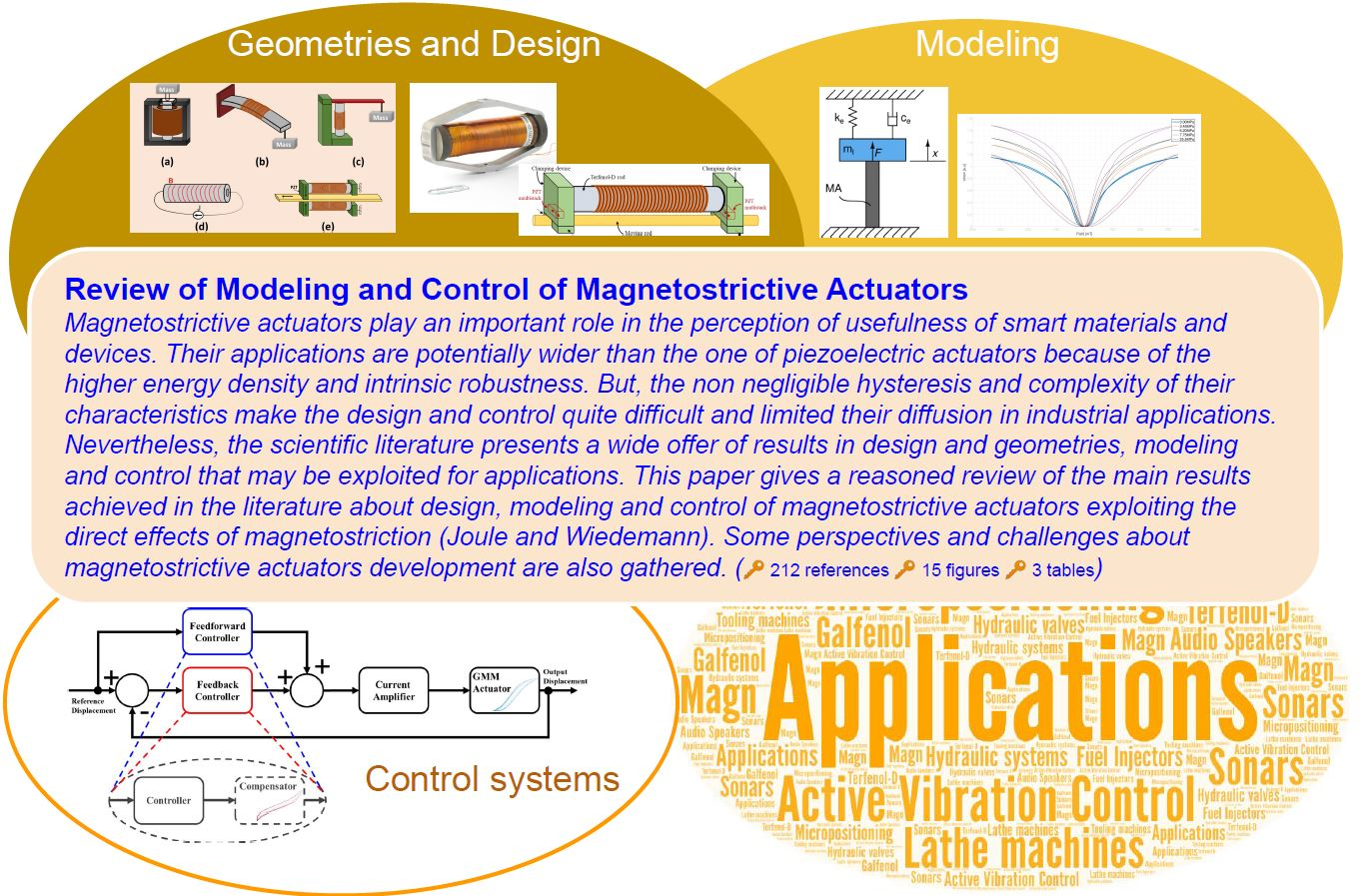
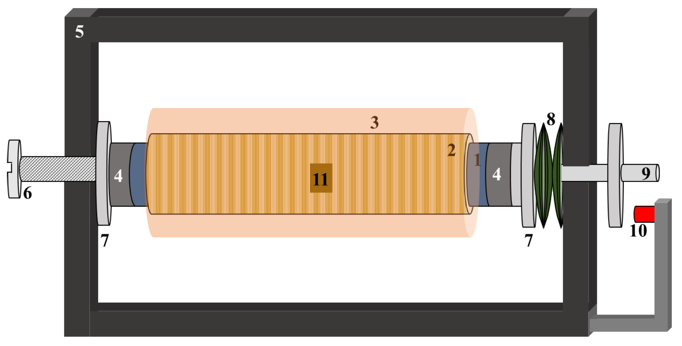
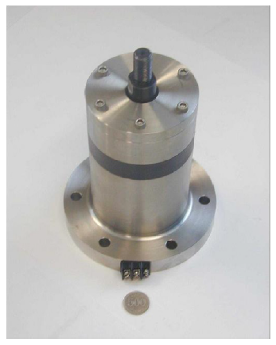
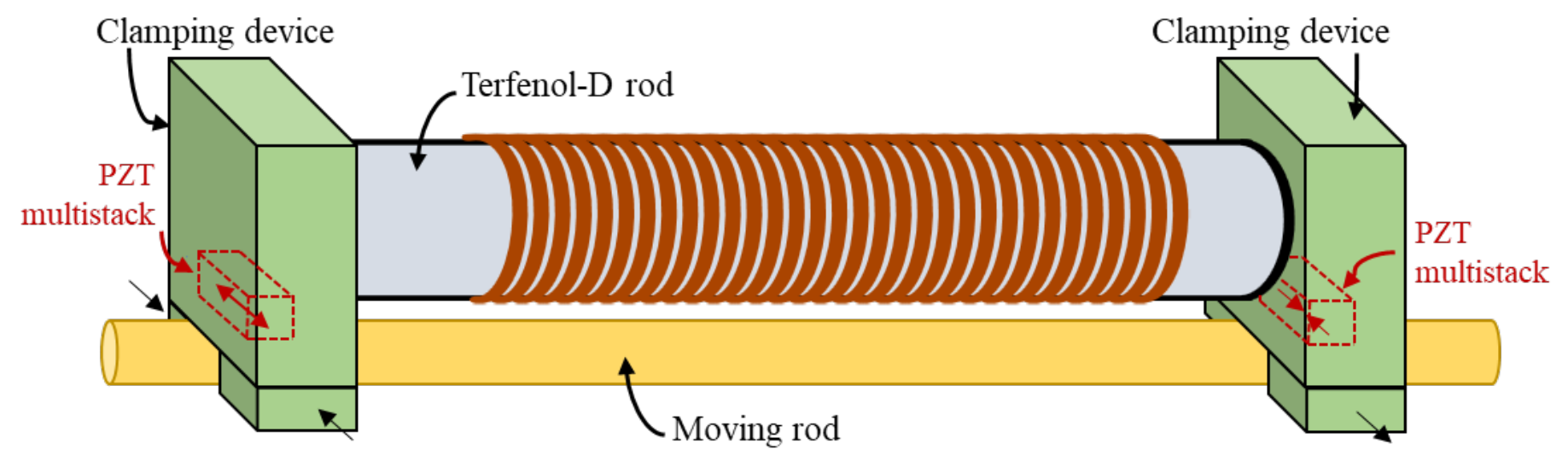
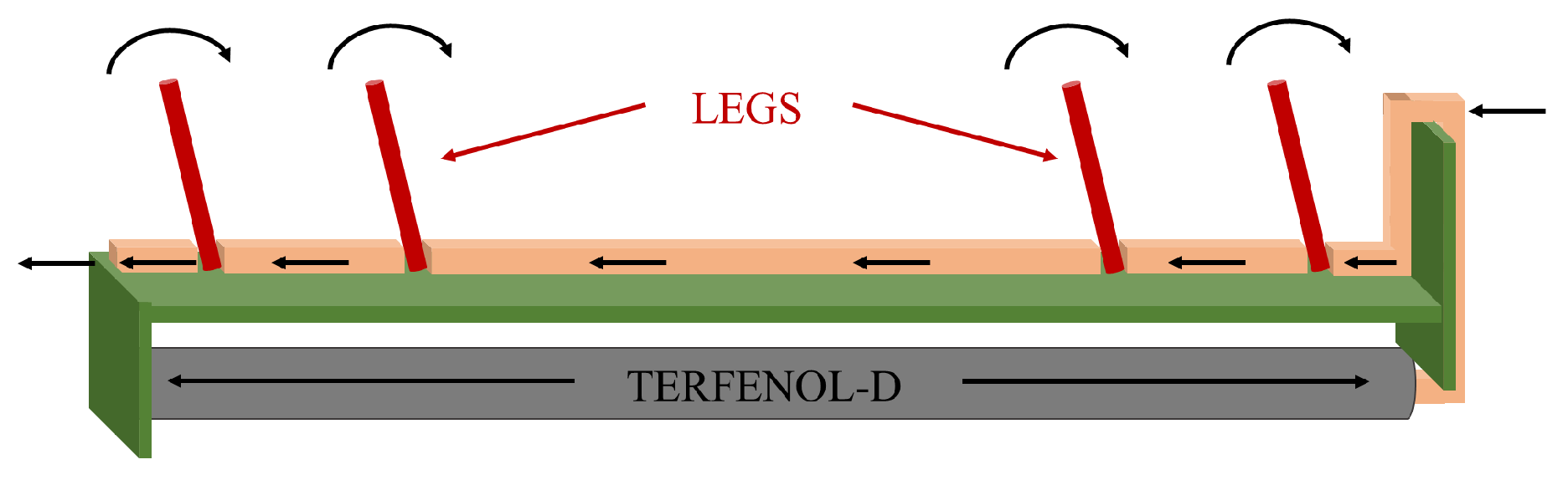
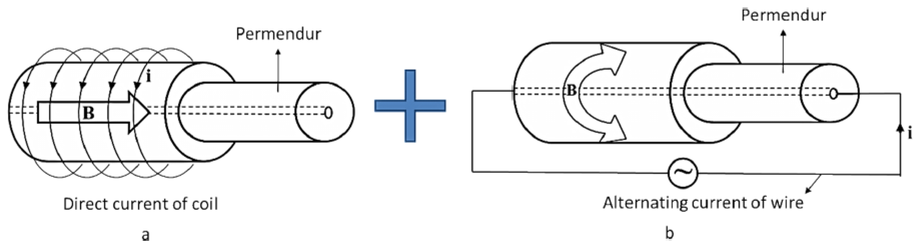
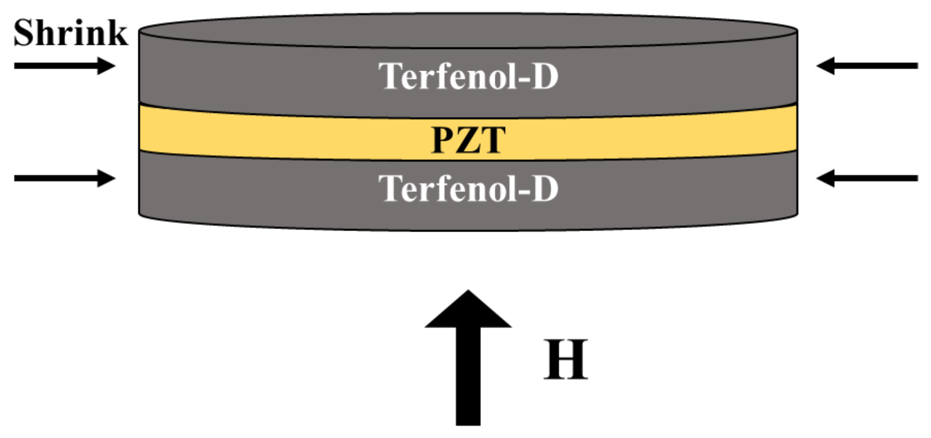
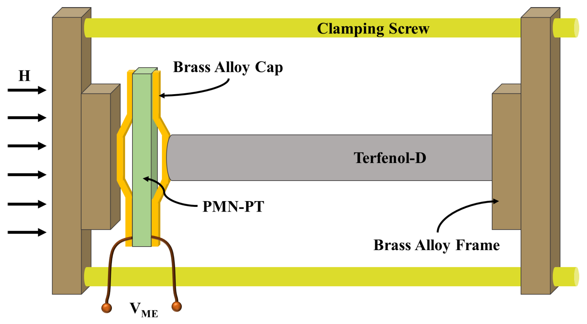
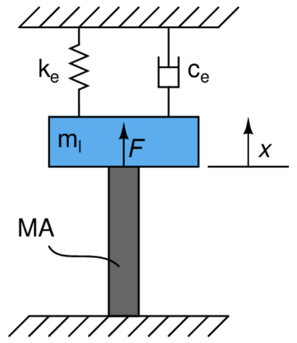
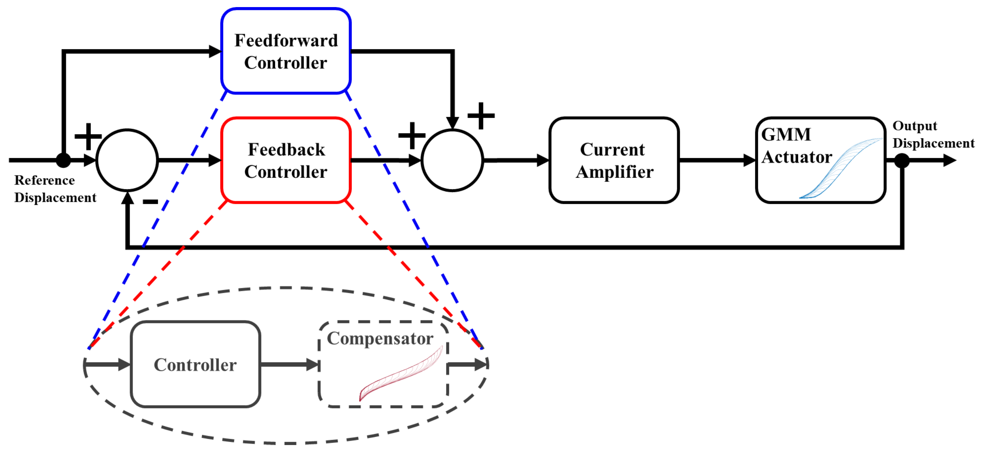
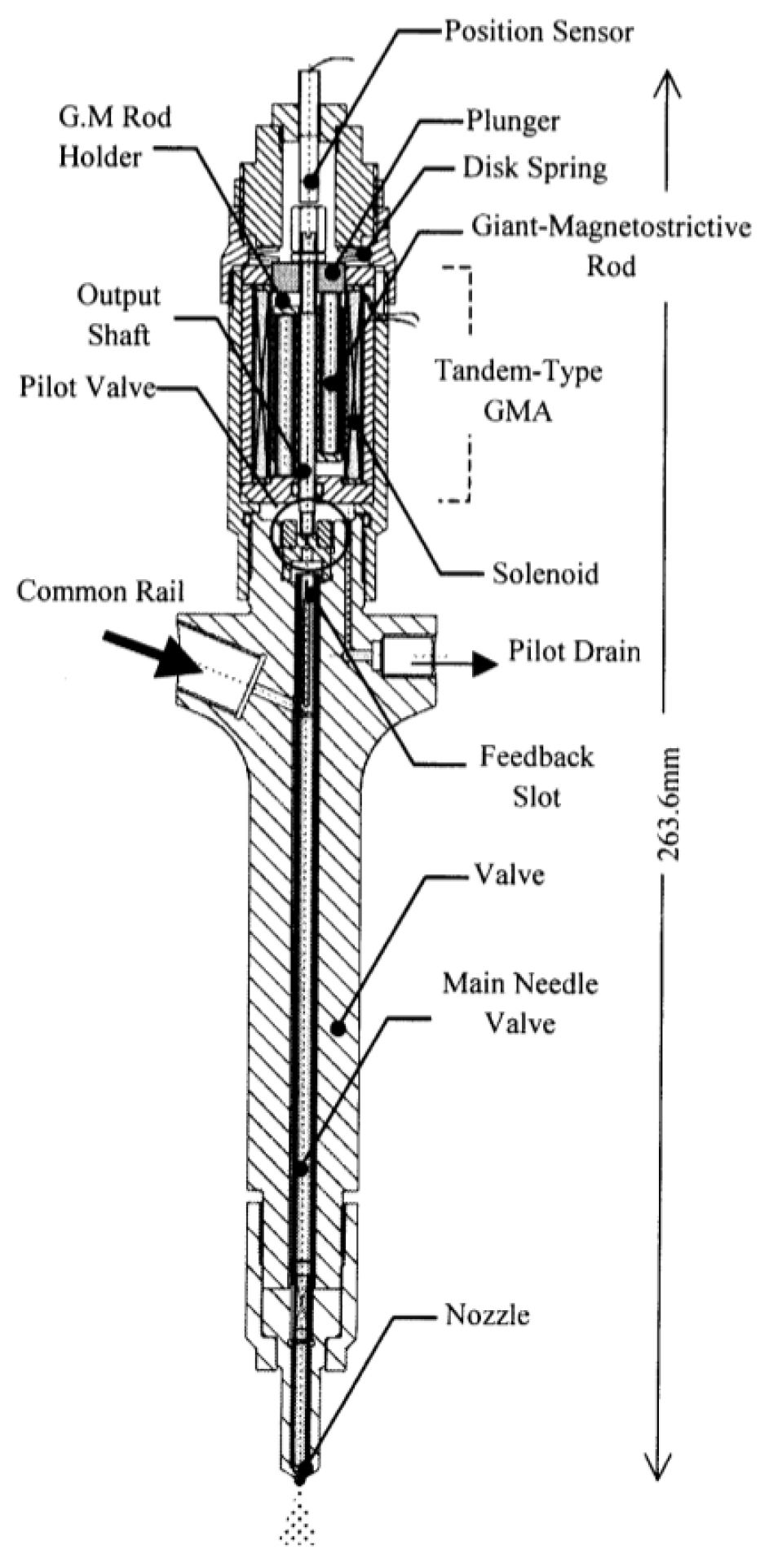
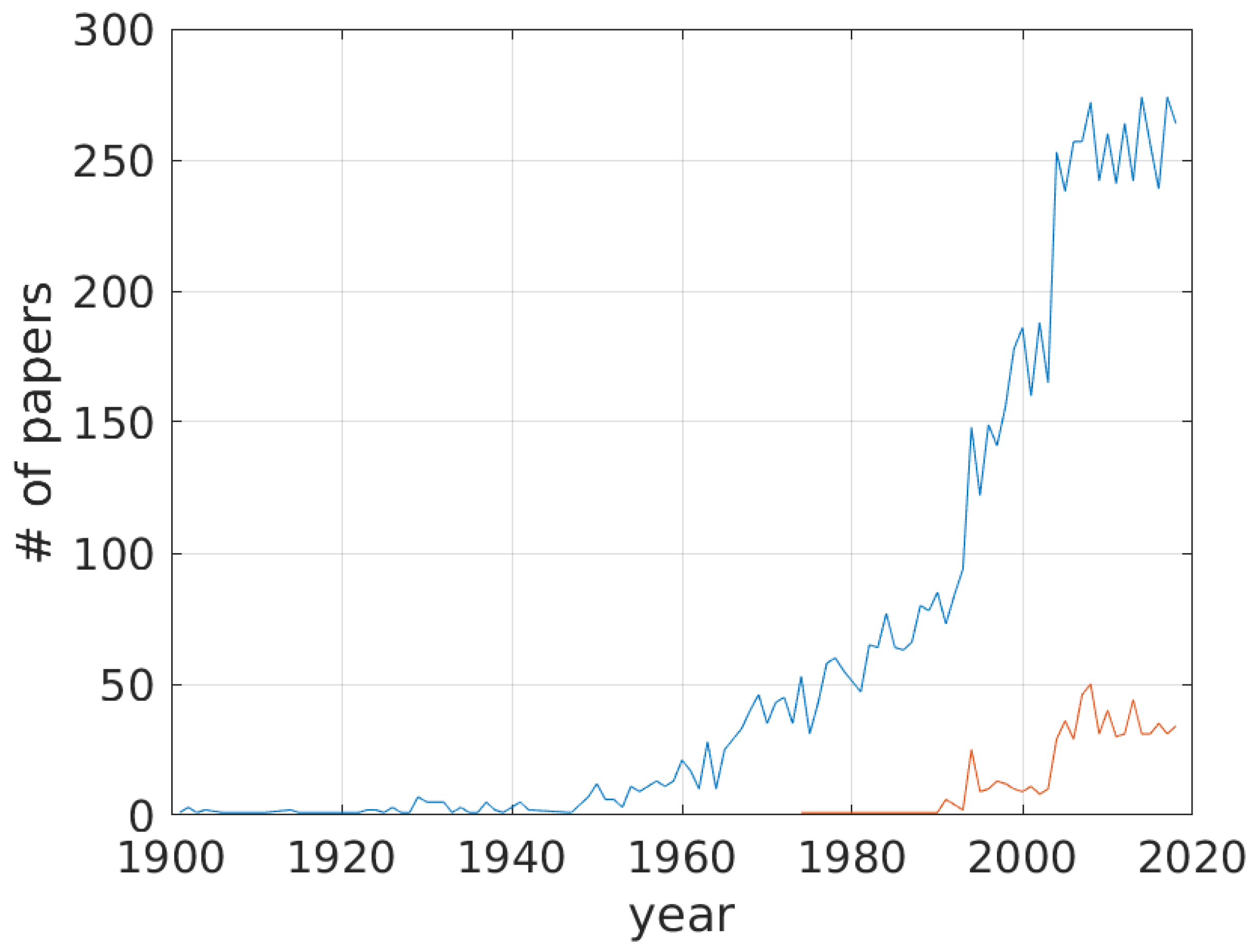
Table 1.
The magnetostrictive effects with available reviews in the literature. The sketches are simplified for an immediate visualization. H is the magnetic field, M is the magnetization, x is the longitudinal deformation, is the longitudinal stress, and are a longitudinal and a circular magnetic field respectively, green arrows show an applied or induced torque.
| Effect: | Joule (Direct) | Villari (Inverse) | Wiedemann | Matteucci |
|---|---|---|---|---|
| Application: | Actuation | Sensing/Harvesting | Actuation/Torque | Sensing |
| Sketch: |  |  |  |  |
| Reviews: | This review [9,10,11] | [12,13,14,15] | This review [5] | [5,8] |
Table 2.
Summary of the main geometrical configurations found for MA and related references.
| Linear | Cantilever | Amplified | Inchworm | Others |
|---|---|---|---|---|
| [36,47,69,70,71,72,73,74,75,76,77,78] | [29,39,79,80,81,82,83,84,85,86] | [50,87,88,89,90,91,92,93,94,95,96,97,98] | [38,40,42,43,88,89,99,100,101,102] | [103,104,105,106] |
 |  |  |  |  |
Table 3.
Main papers, found in the literature, identified according to the geometry (rows) and type of modeling (columns). 0-D is equivalent to a lumped model.
Table 3.
Main papers, found in the literature, identified according to the geometry (rows) and type of modeling (columns). 0-D is equivalent to a lumped model.
| Linear | Nonlinear | Mechanical Dynamics | Electro-Magnetic Dynamics | Hysteresis | |
|---|---|---|---|---|---|
| 0-D | [23,70,72,75,125,126,129,130] | [10,23,34,51,135,139,140] | [23,132,135] | [10,23,55,75,132,135,138,148,166] | [10,51,52,53,54,55,56,60,61,62,64,65,66,94,128,132,139,140,141,142,143,144,145,146,148,149,151,154,155,156,157,158,159,161,162,163,164,166,167,168,169,170,173,178,179,180] |
| 1-D | [23,70] | [23,57,131,134] | [10,34,64,72,128,129,130,131,139,144,145] | [61] | |
| 2-D | [23] | [23,34,60,137,138,146] | [60,137,151] | [60,136,168] | |
| 3-D | [23] | [58,59] | [94] | [62,169] |
© 2019 by the authors. Licensee MDPI, Basel, Switzerland. This article is an open access article distributed under the terms and conditions of the Creative Commons Attribution (CC BY) license (http://creativecommons.org/licenses/by/4.0/).
Share and Cite
MDPI and ACS Style
Apicella, V.; Clemente, C.S.; Davino, D.; Leone, D.; Visone, C. Review of Modeling and Control of Magnetostrictive Actuators. Actuators 2019, 8, 45. https://doi.org/10.3390/act8020045
AMA Style
Apicella V, Clemente CS, Davino D, Leone D, Visone C. Review of Modeling and Control of Magnetostrictive Actuators. Actuators. 2019; 8(2):45. https://doi.org/10.3390/act8020045
Chicago/Turabian StyleApicella, Valerio, Carmine Stefano Clemente, Daniele Davino, Damiano Leone, and Ciro Visone. 2019. "Review of Modeling and Control of Magnetostrictive Actuators" Actuators 8, no. 2: 45. https://doi.org/10.3390/act8020045
Note that from the first issue of 2016, this journal uses article numbers instead of page numbers. See further details here.