Structural-Parametric Model and Diagram of a Multilayer Electromagnetoelastic Actuator for Nanomechanics

Institute of Microdevices and Control Systems, National Research University of Electronic Technology (MIET), 124498 Moscow, Russia
Actuators 2019, 8(3), 52; https://doi.org/10.3390/act8030052
Submission received: 20 May 2019
/
Revised: 22 June 2019
/
Accepted: 24 June 2019
/
Published: 29 June 2019
Abstract
:In this work, the parametric structural schematic diagrams of a multilayer electromagnetoelastic actuator and a multilayer piezoactuator for nanomechanics were determined in contrast to the electrical equivalent circuits of a piezotransmitter and piezoreceiver, the vibration piezomotor. The decision matrix equation of the equivalent quadripole of the multilayer electromagnetoelastic actuator was used. The structural-parametric model, the parametric structural schematic diagram, and the matrix transfer function of the multilayer electromagnetoelastic actuator for nanomechanics were obtained.
1. Introduction
A multilayer actuator provides an increase in the range of movement from a few nanometers to tens of micrometers in nanomechanical systems for nanotechnology and adaptive optics. In this work, the parametric structural schematic diagrams of a multilayer electromagnetoelastic actuator and a multilayer piezoactuator are determined in contrast to the electrical equivalent circuits of a piezotransmitter and piezoreceiver, the vibration piezomotor [1,2,3,4,5,6,7,8,9,10,11,12]. An investigation of the static and dynamic characteristics of the multilayer piezoactuator was necessary for the calculation of nanomechanical systems in the scanning tunneling microscope and the atomic force microscope used for nanotechnology [7,8,9,10,11,12,13,14,15,16,17,18,19,20,21,22,23,24,25,26,27,28,29]. In this work, the solution from the matrix equation of the equivalent quadripole of the multilayer electromagnetoelastic actuator was used compared with the solution from the wave equation presented in my article [25].
Using the decision matrix equation of the equivalent quadripole of the multilayer electromagnetoelastic actuator, with an allowance for the corresponding equation for electromagnetoelasticity and the boundary conditions on its working faces, we constructed the structural-parametric model of the multilayer electromagnetoelastic actuator [8,9,14,16]. The matrix transfer function and the parametric structural schematic diagram of the multilayer electromagnetoelastic actuator were obtained from its structural-parametric model.
2. Parametric Structural Schematic Diagram of the Multilayer Electromagnetoelastic Actuator
In general, the equation for electromagnetoelasticity [11,14,16,20] has the following form:
where , , , , and represent the relative displacement, the electromagnetoelasticity coefficient (piezomodule or magnetostrictive coefficient ), the generalized control parameter (electric , magnetic , field strength or electric induction), the elastic compliance with , and the mechanical stress, respectively, and i, j, and m are indexes.
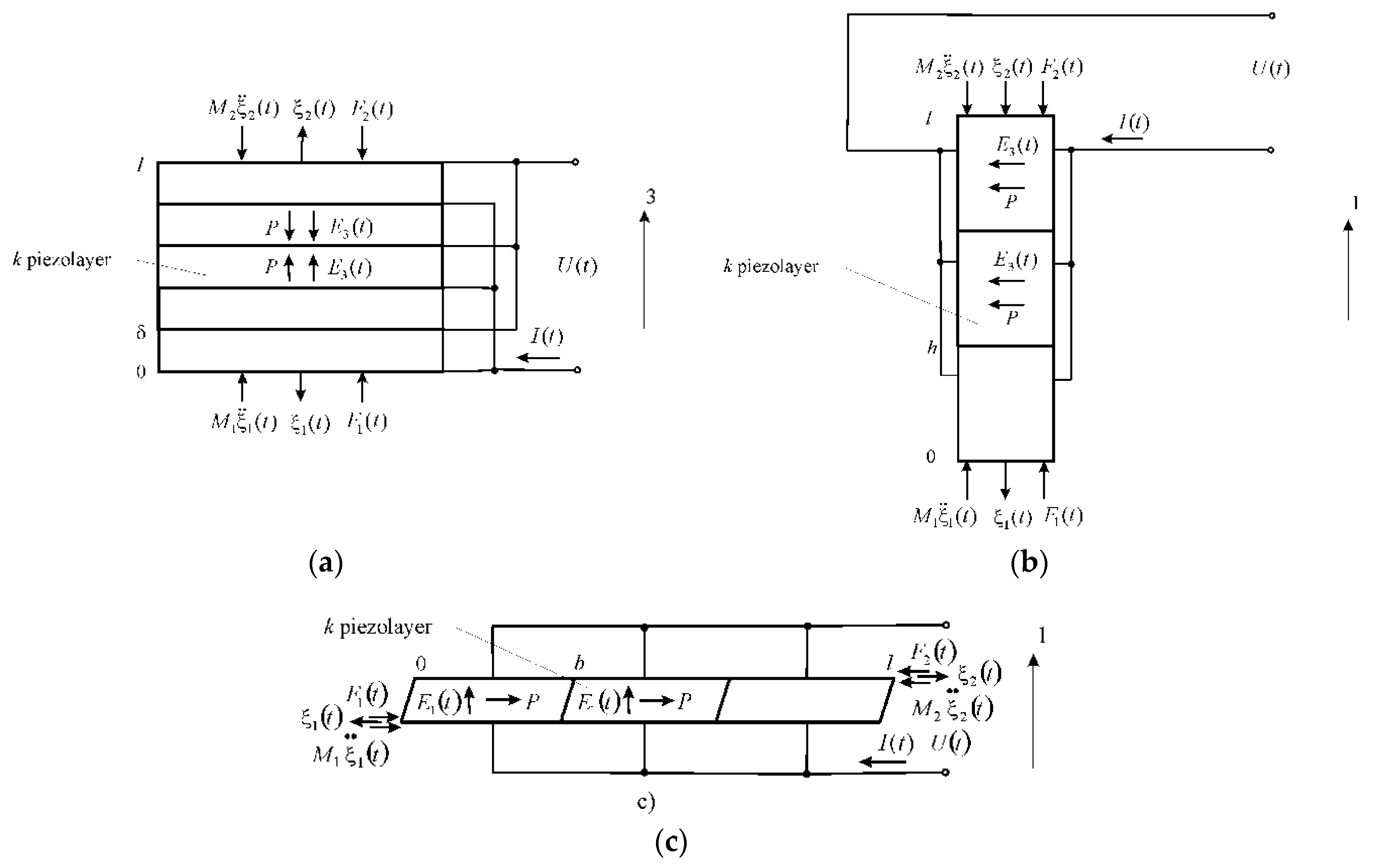
The multilayer piezoactuator in Figure 1 consists of piezolayers or piezoplates connected electrically in parallel and mechanically in series. Let us construct the structural-parametric model of the multilayer piezoactuator for the multilayer piezoactuator at the longitudinal piezoelectric effect, where , , , , and :
The Laplace transform of the force, which causes the deformation, has the following form:
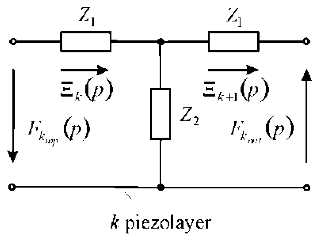
We consider the matrix equation for the Laplace transforms of the forces and the displacements [16] at the input and output ends of the k piezolayer of the multilayer piezoactuator from n piezolayers. The equivalent T-shaped quadripole of the k piezolayer is shown in Figure 2.
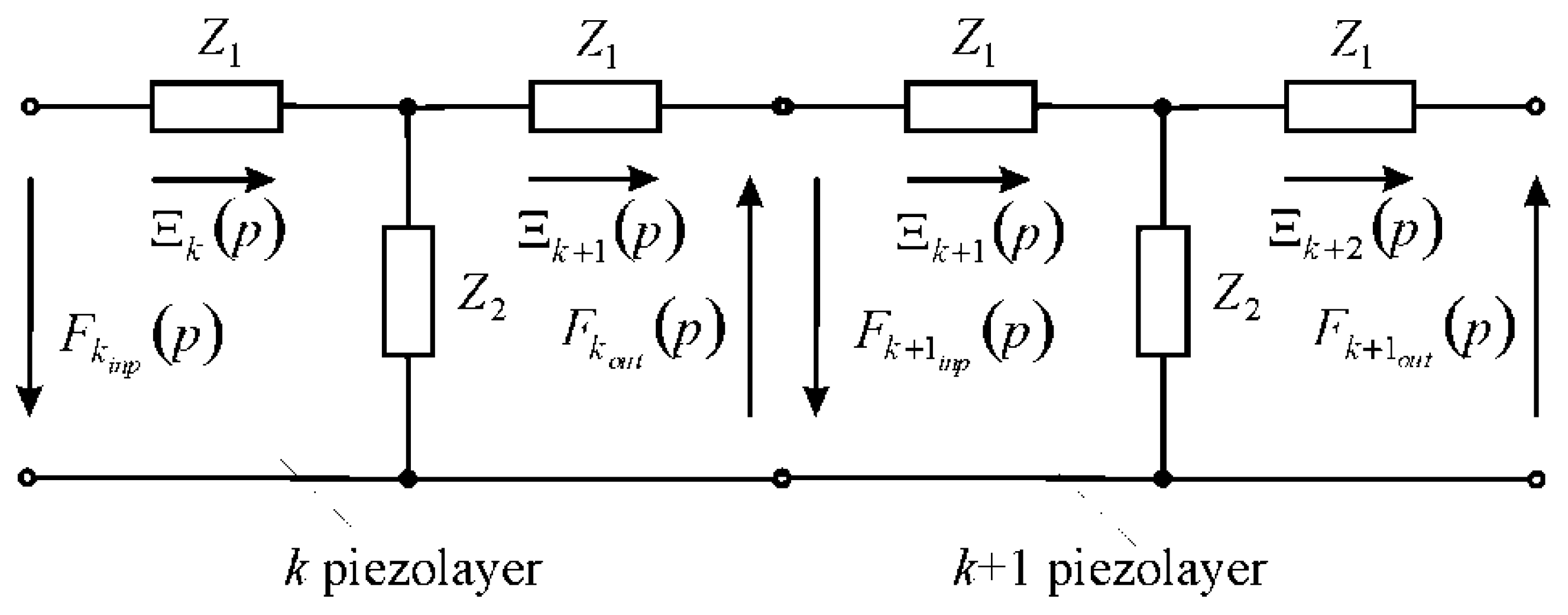
The circuit of the multilayer piezoactuator in Figure 3 is compiled from the equivalent T-shaped quadripole for the k piezolayer and the forces equations, acting on the faces of the piezolayer. Therefore, we have the Laplace transforms of the corresponding forces on the input and output faces of the k piezolayer of the multilayer piezoactuator in Figure 2 and Figure 3 in the form of the system of the equations for the equivalent T-shaped quadripole in the following form:
where , represent the resistance of the equivalent quadripole of the k piezolayer, δ is the thickness, is the coefficient of wave propagation (, and p is the Laplace operator, is the speed of sound in the piezoceramics with , is the attenuation coefficient), , are the Laplace transforms of the forces on the input and output ends of the k piezolayer, and , are the Laplace transforms of the displacements at the input and output ends of the k piezolayer.
Accordingly, we have the Laplace transforms for the following system of the equations for the k piezolayer in Figure 2 in the following form:
the matrix equation for the k piezolayer:
and the matrix in the following form:
where , , , and .
For the multilayer piezoactuator of the Laplace transform, the displacement and the force , acting on the output face of the k piezolayer in Figure 3, correspond to the Laplace transforms of the displacement and the force, acting on the input face of the k + 1 piezolayer.
The force on the output face for the k piezolayer is equal in amplitude and opposite in direction to the force on the input face for the k + 1 piezolayer:
From Equation (7), the matrix equation for the n piezolayers of the multilayer piezoactuator, we obtain the following form:
with the matrix multilayer piezoactuator for the longitudinal piezoeffect (see Figure 1a) in the following form:
The equations of the forces acting on the faces of the multilayer piezoactuator are as follows:
where and are the Laplace transforms of the mechanical stresses at two faces of the multilayer piezoactuator and is the cross-sectional area.
We have the Laplace transforms of the displacements and the forces for the first and second faces of the multilayer piezoactuator in the following form:
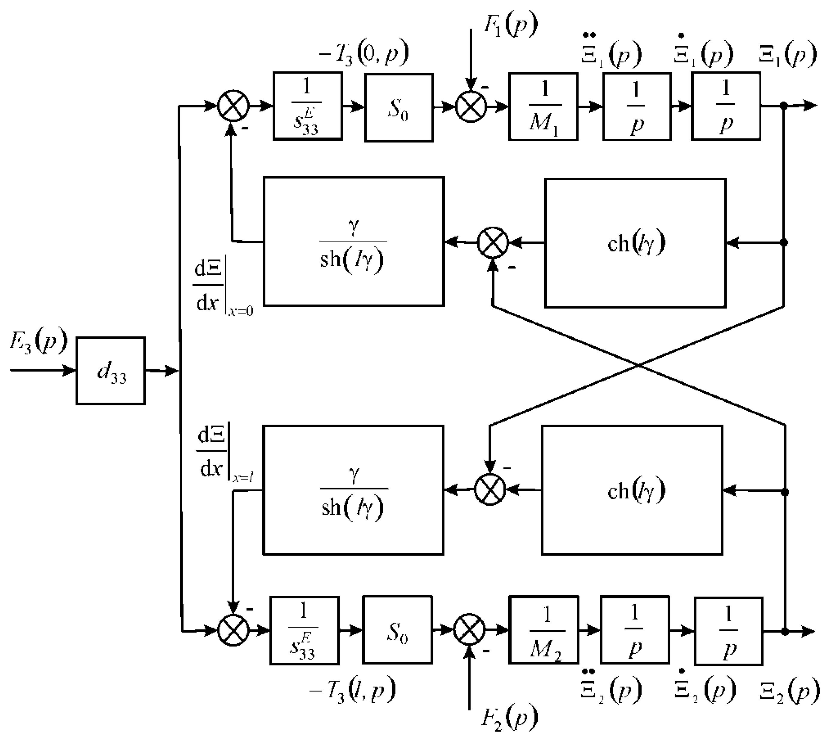
The structural-parametric model of the multilayer piezoactuator for longitudinal piezoeffect with in Figure 4 is obtained from the result analysis of the equation of the force (3) that causes deformation, the system of the equations for the equivalent quadripole of the multilayer piezoactuator (9) and (10), and the equation of the forces (11) on its faces in the following form:
where .
For the multilayer piezoactuator at the transverse piezoelectric effect, where , , , , and , we obtain the following:
The Laplace transform of the force, which causes the deformation, has the following form:
The matrix multilayer piezoactuator for the transverse piezoeffect (see Figure 1b) has the following form:
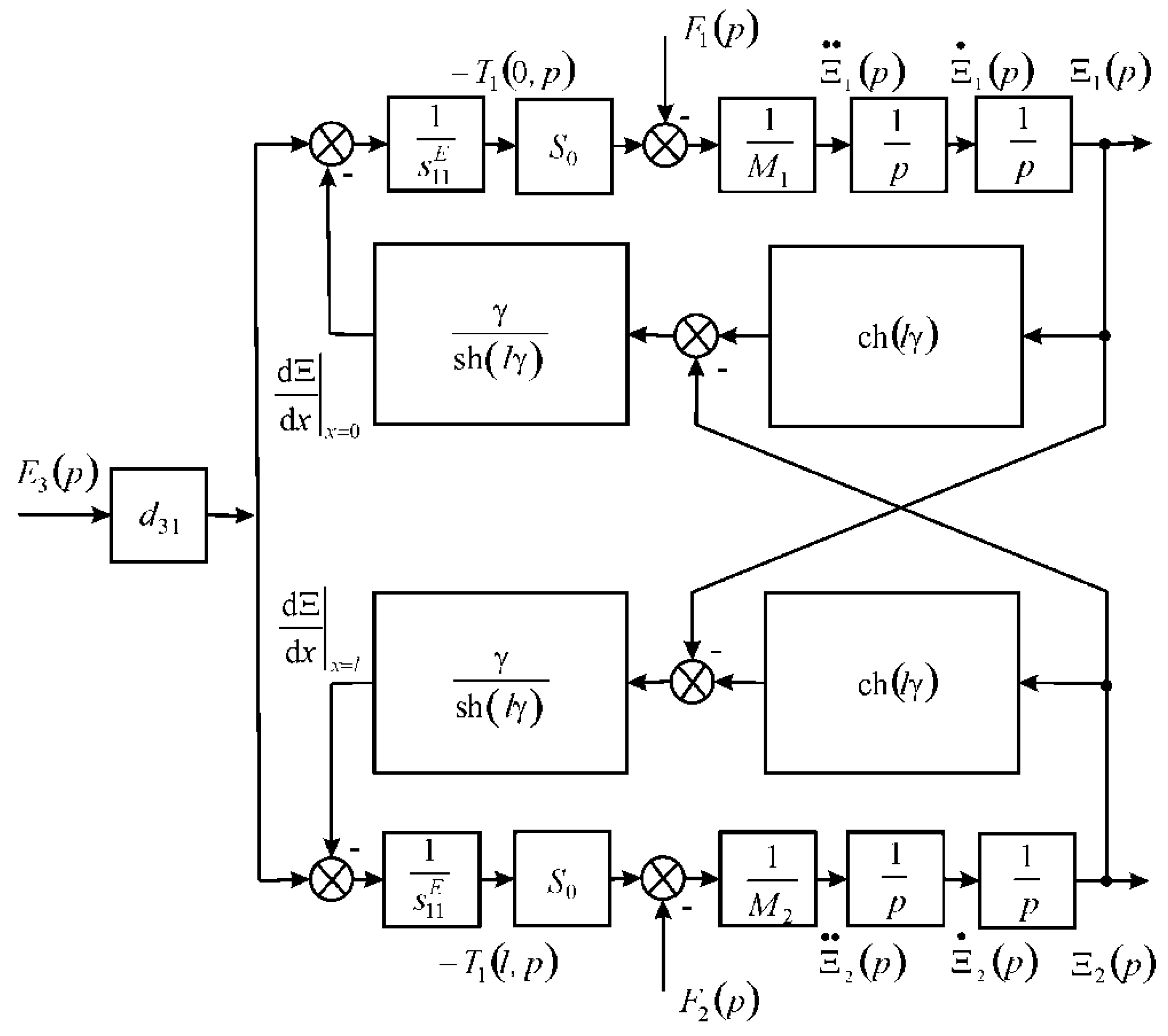
The structural-parametric model of the multilayer piezoactuator for the transverse piezoeffect in Figure 5 with length is obtained from the result analysis of Equations (11), (15) and (16) in the following form:
where .
For the multilayer piezoactuator at the shift piezoelectric effect, where , , , , and , we obtain the following:
The Laplace transform of the force, which causes the deformation, has the following form:
The matrix multilayer piezoactuator for the shift piezoeffect (see Figure 1c) has the following form:
The structural-parametric model of the multilayer piezoactuator for shift piezoeffect with length is obtained from the result analysis of Equations (11), (19) and (20) in the following form:
where .
For the multilayer magnetostrictive actuator at the longitudinal magnetostrictive effect, where , , , , and , we obtain the following:
The Laplace transform of the force, which causes the deformation, has the following form:
The matrix multilayer piezoactuator for the longitudinal magnetostrictive effect has the following form:
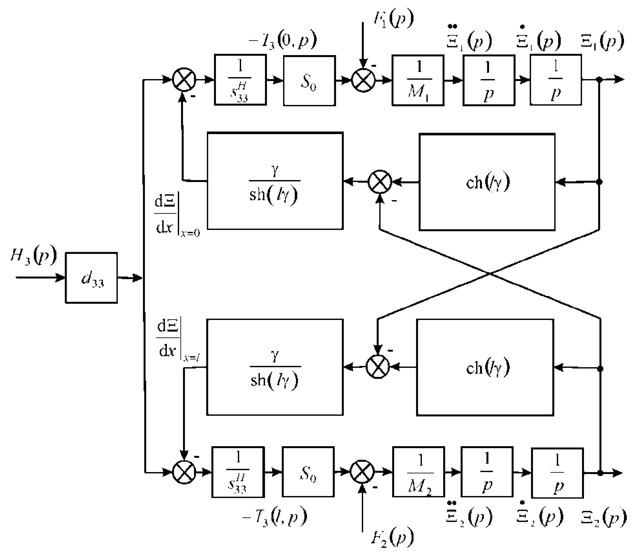
The structural-parametric model of the multilayer magnetostrictive actuator for the longitudinal magnetostrictive effect and the parametric structural schematic diagram in Figure 6 with are obtained from the result analysis of Equations (11), (23) and (24) in the following form:
where .
For the multilayer magnetostrictive actuator at the transverse magnetostrictive effect, where , , , , and , we obtain the following:
The Laplace transform of the force, which causes the deformation, has the following form:
The matrix multilayer magnetostrictive actuator for the transverse magnetostrictive effect has the following form:
The structural-parametric model of the multilayer magnetostrictive actuator for the transverse magnetostrictive effect with is obtained from Equations (11), (27) and (28) in the following form:
where .
For the multilayer magnetostrictive actuator at the shift magnetostrictive effect, where , , , , and , we obtain the following:
The Laplace transform of the force, which causes the deformation, has the following form:
The matrix multilayer magnetostrictive actuator for the shift magnetostrictive effect has the following form:
The structural-parametric model of the multilayer magnetostrictive actuator for the shift magnetostrictive effect with length is obtained from the result analysis of Equations (11), (31) and (32) in the following form:
where .
Therefore, in general, from (1) for the multilayer electromagnetoelastic actuator, the Laplace transform of the force that causes deformation has the following form:
where and is the cross-sectional area of the multilayer actuator.
Accordingly, in general, the matrix for the equivalent quadripole of the multilayer electromagnetoelastic actuator has the following form:
From Equation (35), we have the equivalent quadripole of the multilayer piezoactuator in Figure 1a–c for the longitudinal piezoeffect with length of the multilayer piezoactuator being , for the transverse piezoeffect being , and for the shift piezoeffect being , where are the thickness, the height, and the width for the k piezolayer, respectively.
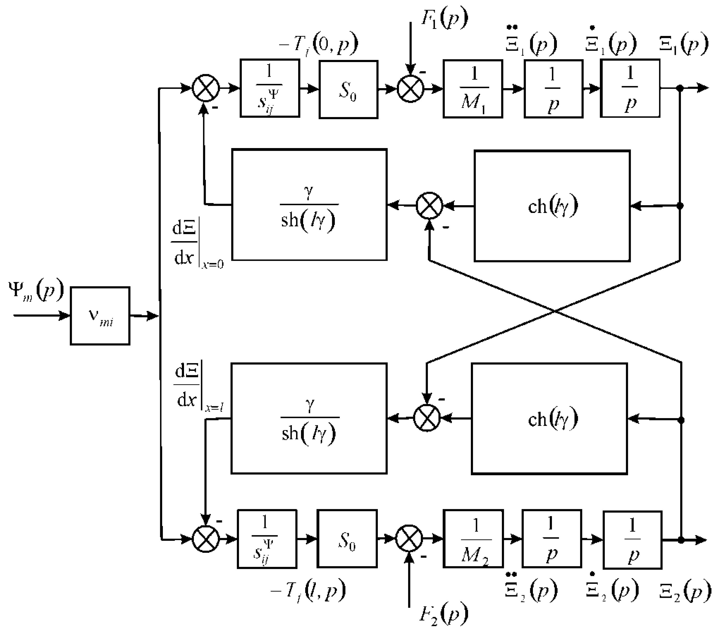
We obtain the equations for the generalized structural-parametric model and the generalized parametric structural schematic diagram in Figure 7 of the multilayer electromagnetoelastic actuator from the result analysis of the equation of the force (34) that causes deformation, the system of the equations for the equivalent quadripole (35), and the equation of the forces (11) on its faces in the following form:
where , , , , , .
3. Matrix Transfer Function of the Multilayer Electromagnetoelastic Actuator
From Equation (36), we have in general the matrix transfer function of the multilayer electromagnetoelastic actuator in the following form:
where is the matrix of the displacements, is the matrix of the control parameters, and is the matrix transfer function, where
- ,
- ,
- ,
- ,
- ,
where .
For example, for the voltage-controlled multilayer piezoactuator at the longitudinal piezoeffect, we have the following transfer functions:
where .
For the voltage-controlled multilayer piezoactuator, the static displacements of its faces at the longitudinal piezoeffect and the inertial load at , and have the following form:
where is the amplitude of the voltage, is the mass of the multilayer piezoactuator, and are the load masses. For the multilayer piezoactuator from the piezoceramics type PZT at = 4 × 10⁻¹⁰ m/V, = 8, = 100 V, = 1.5 kg and = 6 kg, we obtain the static displacements of the faces = 256 nm, = 64 nm, and = 320 nm.
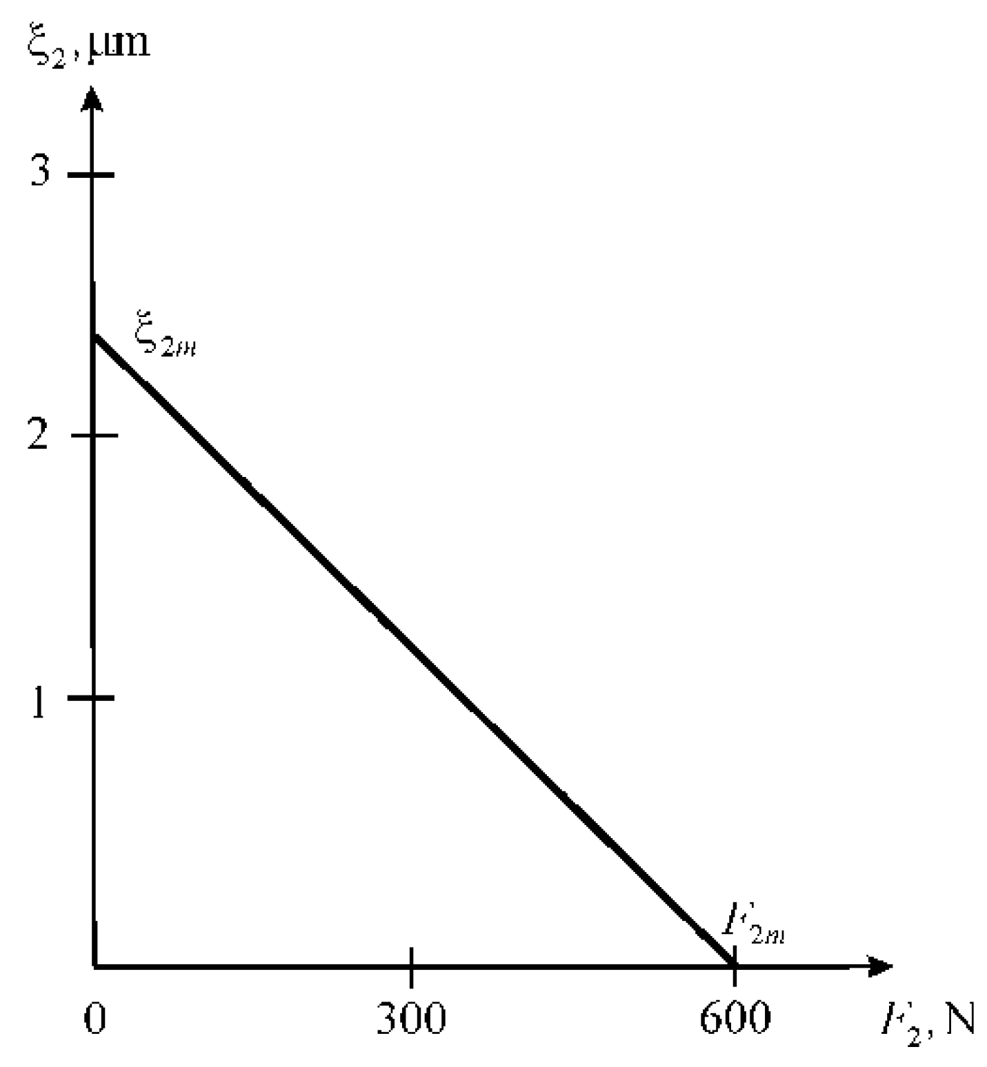
Let us consider a static characteristic multilayer piezoactuator with one fixed face at the longitudinal piezoeffect with the voltage control. In Figure 8, we have maximum displacement for and maximum force for in the following form:
For the voltage-controlled multilayer piezoactuator at the longitudinal piezoeffect from the piezoceramics type PZT with one fixed face at = 4 × 10⁻¹⁰ m/V, = 6 × 10⁻⁴ m, = 40, = 1.8 × 10⁻⁴ m2, = 3 × 10⁻¹¹ m2/N, and = 150 V, we obtain the Figure 8 values of maximum displacement = 2.4 μm and maximum force = 600 N. The measurements were made on a Universal testing machine UMM-5, Russia in the range of working loads under mechanical stresses in the multilayer piezoactuator up to 100 MPa. The discrepancy between the experimental data and the calculation results is 5%.
From Equation (38), we have the transfer function with lumped parameters of the multilayer piezoactuator for the longitudinal piezoeffect at the voltage control and the elastic-inertial load in the following form:
where and are the Laplace transforms of the displacement face and the voltage, and are the time constant and the damping coefficient, and is the rigidity piezoeffect for .
Therefore, we obtain the static displacement of the multilayer piezoactuator in the following form:
where is the steady-state value of the displacement face and is the amplitude of the voltage.
From Equation (43), the expression for the transient response of the voltage-controlled piezoactuator for the elastic-inertial load under the longitudinal piezoeffect is determined in the following form:
For the voltage-controlled multilayer piezoactuator from the piezoceramics type PZT with one fixed face for longitudinal piezoeffect and elastic-inertial load at = 4 × 10⁻¹⁰ m/V, = 10, = 60 V, = 9 kg, = 3 × 10⁷ N/m, and = 0.6 × 10⁷ N/m, the steady-state value of the displacement face = 200 nm and the time constant = 0.5 × 10⁻³ s are obtained.
4. Results and Discussion
We obtained the generalized structural-parametric model, the generalized parametric structural schematic diagram, and the matrix equation of the multilayer electromagnetoelastic actuator from the equation of the force, that causes deformation, and the matrix equation of the equivalent quadripole of the multilayer actuator, as well as the equations of the forces on its faces. From the generalized structural-parametric model of the multilayer electromagnetoelastic actuator, we obtained the structural-parametric models of the multilayer piezoelectric or magnetostrictive actuators.
The decision matrix equation of the equivalent quadripole of the multilayer electromagnetoelastic actuator was used. We derived the generalized matrix for the equivalent quadripole of the multilayer electromagnetoelastic actuator.
We obtained the structural schematic diagrams of the multilayer electromagnetoelastic actuator and the multilayer piezoactuator in contrast to the electrical equivalent circuits of the piezotransmitter and piezoreceiver, the vibration piezomotor.
The structural-parametric model and the parametric structural schematic diagrams of the multilayer piezoactuator for the longitudinal, transverse, and shift piezoelectric effects were determined from its structural-parametric models. The static and dynamic characteristics of the multilayer piezoactuator were constructed for nanomechanics.
5. Conclusions
In this work, we obtained the generalized structural-parametric model of the multilayer electromagnetoelastic actuator from the equation of the force that causes deformation, the system of the equations for the equivalent quadripole of the multilayer actuator, and the equations of the forces on its faces. We obtained the generalized matrix for the equivalent quadripole of the multilayer electromagnetoelastic actuator and the matrixes for the equivalent quadripole of the multilayer piezoelectric or magnetostrictive actuators.
We also determined the generalized parametric structural schematic diagram and the generalized matrix transfer function of the multilayer electromagnetoelastic actuator and, from this, the generalized structural-parametric model. We derived the structural schematic diagrams of the multilayer electromagnetoelastic actuator and the multilayer piezoactuator in contrast to the electrical equivalent circuits of the piezotransducer, the vibration piezomotor.
Finally, we determined the parametric structural schematic diagram and the matrix transfer function of the multilayer piezoactuator for the transverse, longitudinal, and shift piezoelectric effects for nanomechanics. From the matrix transfer function of the multilayer piezoactuator, we obtained the static and dynamic characteristics of the multilayer piezoactuator.
Funding
This research received no external funding.
Conflicts of Interest
The authors declare no conflict of interest.
References
- Schultz, J.; Ueda, J.; Asada, H. Cellular Actuators; Butterworth-Heinemann Publisher: Oxford, UK, 2017; p. 382. [Google Scholar]
- Afonin, S.M. Absolute stability conditions for a system controlling the deformation of an elecromagnetoelastic transduser. Dokl. Math. 2006, 3, 943–948. [Google Scholar] [CrossRef]
- Zhou, S.; Yao, Z. Design and optimization of a modal-independent linear ultrasonic motor. IEEE Trans. Ultrason. Ferroelectr. Freq. Control 2014, 3, 535–546. [Google Scholar] [CrossRef] [PubMed]
- Przybylski, J. Static and dynamic analysis of a flextensional transducer with an axial piezoelectric actuation. Eng. Struct. 2015, 84, 140–151. [Google Scholar] [CrossRef]
- Ueda, J.; Secord, T.; Asada, H.H. Large effective-strain piezoelectric actuators using nested cellular architecture with exponential strain amplification mechanisms. IEEE/ASME Trans. Mechatron. 2010, 15, 770–782. [Google Scholar] [CrossRef]
- Karpelson, M.; Wei, G.-Y.; Wood, R.J. Driving high voltage piezoelectric actuators in microrobotic applications. Sens. Actuators A Phys. 2012, 78–89. [Google Scholar] [CrossRef]
- Afonin, S.M. Block diagrams of a multilayer piezoelectric motor for nano- and microdisplacements based on the transverse piezoeffect. J. Comput. Syst. Sci. Int. 2015, 3, 424–439. [Google Scholar] [CrossRef]
- Afonin, S.M. Structural parametric model of a piezoelectric nanodisplacement transduser. Dokl. Phys. 2008, 3, 137–143. [Google Scholar] [CrossRef]
- Afonin, S.M. Solution of the wave equation for the control of an elecromagnetoelastic transduser. Dokl. Math. 2006, 2, 307–313. [Google Scholar] [CrossRef]
- Cady, W.G. Piezoelectricity: An Introduction to the Theory and Applications of Electromechancial Phenomena in Crystals; McGraw-Hill Book Company: New York, NY, USA; London, UK, 1946; p. 806. [Google Scholar]
- Mason, W. Physical Acoustics: Principles and Methods. Volume I. Part A. Methods and Devices; Academic Press: New York, NY, USA, 1964; Volume 1, p. 515. [Google Scholar]
- Chiatto, M.; Capuano, F.; Coppola, G.; de Luca, L. LEM characterization of synthetic jet actuators driven by piezoelectric element: A Review. Sensors 2017, 17, 1216. [Google Scholar] [CrossRef] [PubMed]
- Afonin, S.M. Structural-parametric model and transfer functions of electroelastic actuator for nano- and microdisplacement. In Piezoelectrics and Nanomaterials: Fundamentals, Developments and Applications; Chapter 9; Parinov, I.A., Ed.; Nova Science: New York, NY, USA, 2015; pp. 225–242. [Google Scholar]
- Afonin, S.M. A structural-parametric model of electroelastic actuator for nano- and microdisplacement of mechatronic system. In Advances in Nanotechnology; Chapter 8; Bartul, Z., Trenor, J., Eds.; Nova Science: New York, NY, USA, 2017; Volume 19, pp. 259–284. [Google Scholar]
- Afonin, S.M. Nano- and micro-scale piezomotors. Russ. Eng. Res. 2012, 32, 519–522. [Google Scholar] [CrossRef]
- Afonin, S.M. Generalized parametric structural model of a compound electromagnetoelastic transducer. Dokl. Phys. 2005, 2, 77–82. [Google Scholar] [CrossRef]
- Afonin, S.M. Elastic compliances and mechanical and adjusting characteristics of composite piezoelectric transducers. Mech. Solids 2007, 1, 43–49. [Google Scholar] [CrossRef]
- Afonin, S.M. Stability of strain control systems of nano- and microdisplacement piezotransducers. Mech. Solids 2014, 2, 196–207. [Google Scholar] [CrossRef]
- Afonin, S.M. Structural-parametric model electromagnetoelastic actuator nanodisplacement for mechatronics. Int. J. Phys. 2017, 1, 9–15. [Google Scholar] [CrossRef]
- Afonin, S.M. A block diagram of electromagnetoelastic actuator nanodisplacement for communications Systems. Trans. Netw. Commun. 2018, 3, 1–9. [Google Scholar] [CrossRef]
- Afonin, S.M. Electromagnetoelastic nano- and microactuators for mechatronic systems. Russ. Eng. Res. 2018, 12, 938–944. [Google Scholar] [CrossRef]
- Afonin, S.M. Structural-parametric model of piezoactuator nano- and microdisplacement for nanoscience. AASCIT J. Nanosci. 2017, 3, 12–18. [Google Scholar]
- Afonin, S.M. Wave equation and parametric structural schematic diagrams of electromagnetoelastic actuators nano- and microdisplacement. Int. J. Math. Anal. Appl. 2016, 4, 31–38. [Google Scholar]
- Afonin, S.M. Structural-parametric model electromagnetoelastic actuator nano and microdisplacement for precision engineering. Eng. Technol. 2016, 6, 110–119. [Google Scholar]
- Afonin, S.M. Structural-parametric model of electromagnetoelastic actuator for nanomechanics. Actuators 2018, 1, 6. [Google Scholar] [CrossRef]
- Afonin, S.M. Multilayer electromagnetoelastic actuator for robotics systems of nanotechnology. In Proceedings of the 2018 IEEE Conference of Russian Young Researchers in Electrical and Electronic Engineering (EIConRus), Moscow, Russia, 29 January–1 February 2018; pp. 1698–1701. [Google Scholar] [CrossRef]
- Bhushan, B. Springer Handbook of Nanotechnology; Springer: Berlin, Germany; New York, NY, USA, 2004; p. 1222. [Google Scholar]
- Uchino, K. Piezoelectric Actuator and Ultrasonic Motors; Kluwer Academic Publisher: Boston, MA, USA, 1997; p. 347. [Google Scholar]
- Nalwa, H.S. Encyclopedia of Nanoscience and Nanotechnology; American Scientific Publishers: Los Angeles, CA, USA, 2004. [Google Scholar]
Figure 1.
Kinematic schemes of the multilayer piezoactuator for (a) longitudinal, (b) transverse, and (c) shift piezoeffects, and the k piezolayer.
Figure 1.
Kinematic schemes of the multilayer piezoactuator for (a) longitudinal, (b) transverse, and (c) shift piezoeffects, and the k piezolayer.

Figure 2.
Quadripole for the k piezolayer.

Figure 3.
Circuit of the multilayer piezoactuator with quadripoles for the k and k + 1 piezolayers.

Figure 4.
Parametric structural schematic diagram of the multilayer piezoactuator for longitudinal piezoeffect with voltage control.
Figure 4.
Parametric structural schematic diagram of the multilayer piezoactuator for longitudinal piezoeffect with voltage control.

Figure 5.
Parametric structural schematic diagram of the multilayer piezoactuator for transverse piezoeffect with voltage control.
Figure 5.
Parametric structural schematic diagram of the multilayer piezoactuator for transverse piezoeffect with voltage control.

Figure 6.
Parametric structural schematic diagram of multilayer magnetostrictive actuator for longitudinal magnetostrictive effect with the magnet field strength control.
Figure 6.
Parametric structural schematic diagram of multilayer magnetostrictive actuator for longitudinal magnetostrictive effect with the magnet field strength control.

Figure 7.
Generalized parametric structural schematic diagram of the multilayer electromagnetoelastic actuator.
Figure 7.
Generalized parametric structural schematic diagram of the multilayer electromagnetoelastic actuator.

Figure 8.
Static characteristic multilayer piezoactuator for longitudinal piezoeffect.

© 2019 by the author. Licensee MDPI, Basel, Switzerland. This article is an open access article distributed under the terms and conditions of the Creative Commons Attribution (CC BY) license (http://creativecommons.org/licenses/by/4.0/).
Share and Cite
MDPI and ACS Style
Afonin, S.M. Structural-Parametric Model and Diagram of a Multilayer Electromagnetoelastic Actuator for Nanomechanics. Actuators 2019, 8, 52. https://doi.org/10.3390/act8030052
AMA Style
Afonin SM. Structural-Parametric Model and Diagram of a Multilayer Electromagnetoelastic Actuator for Nanomechanics. Actuators. 2019; 8(3):52. https://doi.org/10.3390/act8030052
Chicago/Turabian StyleAfonin, Sergey M. 2019. "Structural-Parametric Model and Diagram of a Multilayer Electromagnetoelastic Actuator for Nanomechanics" Actuators 8, no. 3: 52. https://doi.org/10.3390/act8030052
Note that from the first issue of 2016, this journal uses article numbers instead of page numbers. See further details here.