Flexible Shape-Memory Alloy-Based Actuator: Mechanical Design Optimization According to Application


Department of Systems Engineering and Automation, Carlos III University of Madrid, Leganés, 28911 Madrid, Spain
*
Author to whom correspondence should be addressed.
†
These authors contributed equally to this work.
Actuators 2019, 8(3), 63; https://doi.org/10.3390/act8030063
Submission received: 15 July 2019
/
Revised: 9 August 2019
/
Accepted: 9 August 2019
/
Published: 14 August 2019
(This article belongs to the Special Issue Actuators Based on Shape Memory Alloys)
Abstract
:New robotic applications, among others, in medical and related fields, have in recent years boosted research in the development of new actuators in the search for solutions that are lighter and more flexible than conventional actuators. Shape-Memory Alloy (SMA)-based actuators present characteristics that make them an excellent alternative in a wide variety of applications. This paper presents the design, tests (with the control description) and analysis of various configurations of actuators based on SMA wires: flexible SMA actuators, different mechanical design to multiply the displacement and different configurations for actuators with multiple SMA wires. The performance of the actuators has been analyzed using wires of different activation temperatures. The influence of the Bowden sheath of the flexible actuator has been tested, as has the thermal behavior of actuators with several wires. This work has allowed determination of the most effective configuration for the development of a flexible actuator based on SMA, from the point of view of dimensions, efficiency, and work frequency. This type of actuator has been applied in the development of soft robots and light robotic exoskeletons.

1. Introduction
In recent years, Shape Memory Alloy (SMA) materials have been considered a promising technology for the development of non-conventional actuators oriented on some specific applications. SMA-based actuators present characteristics which make them suitable to be integrated in a large variety of applications: they have a high force-to-weight ratio and noiseless operation, present a low volume (SMAs can generate about 150 times higher force compared with hydraulic actuators and 400 times higher force compared with magnetic actuators, at the same volume), and are a relatively low-cost solution compared with another actuators. In recent years, SMAs have been used in a widespread variety of applications [1], among them aerospace [2,3], the automotive industry [4,5], medical applications [6], and robotics [7].
Focusing on robotics, one of the limitations in the development of wearable robotic devices lies in the development of lightweight actuators. Thanks to their flexibility, high force-to-weight ratio, and small volume, SMA-based actuators can be considered a good actuation solution for wearable and soft robotic applications and especially for rehabilitation devices. They can be considered an alternative to conventional actuators such as DC and AC motors for robotics applications where a high force at low velocity is needed, or for pneumatic muscles if a low weight, low size, and noiseless operation is required.
Our research group has developed a new flexible SMA actuator that provides more freedom of movement and a better integration in wearable robots, especially in soft wearable robots. This actuator has been presented in previous works [8] (based on only one SMA wire) and [9]. During the design process of this system, several factors that determine the behavior of the final actuator have been considered. Not only must the characteristics of the material be considered [10]; in our case, the effect of other actuator elements (such as the Bowden sheath) modifies the behavior of the complete system.
When the SMA is proposed to be used as actuator in any robotic application, important factors must to be considered to select the most suitable configuration:
- the shape of SMA. The SMA can be wire, spring, ribbon and diaphragm, tubing;
- the temperature of activation (temperature of austenite phase). This can depend on the alloys but in robotics applications the most common are the SMAs activated at C, but the SMA wire activated at C is another possible solution.
- the force they can achieve;
- the technique to heat and cool them, which depends on the thickness of the alloy;
- the adopted control technique;
- the mechanical design of the actuator;
In [11], aspects such as material selection, shape of the active element or the comparison between serial or parallel actuation are analyzed for the design of a wire-based serial SMA actuator. The influence of a grease-filled polytetrafluoroethylene (PTFE) tube on the cooling phase of a SMA wire-based actuator is tested in [12].
In the majority of applications, the actuators based on SMA have a simple design: the two extremities of the SMA wire are crimped, one to the fixed point and another one to the system which will be moved, but different approaches to mechanical configuration design have been proposed to improve the force and total displacement of these:
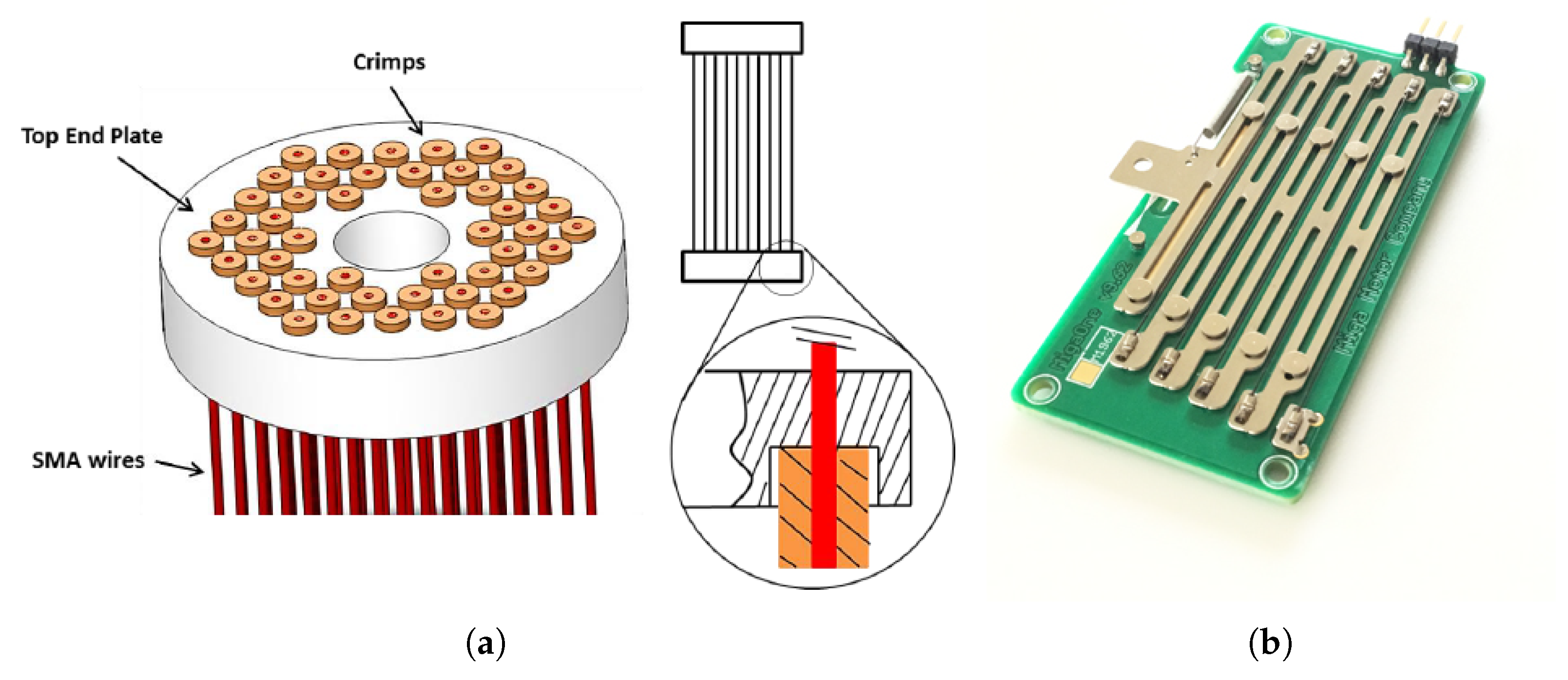
- in [13], 48 SMA wires of 0.15 mm diameter was arranged in parallel configuration between two virgin Teflon end plates (Figure 1a). This configuration can lift more than 100 lbs (approximately 444.8 N). During the experiment, some interesting non-linear characteristics, such as dry friction, saturation, and unpredictability of response for the same input, were detected. Also, the proposed configuration does not offer a flexibility advantage to the actuator.
- in [15] use the deflected flexible beams to amplify the displacement of a SMA actuator and to provide linear motion. The SMA wire is fixed eccentrically along flexible beams which, when the SMA heats, bend, causing a linear displacement of the final actuator.
- in others works, the total displacement of the SMA is increased using systems with a pulley such as in [16]. Here 2.5 m of SMA with 0.25 mm diameter was designed as a cartridge of approximately 150 × 20 × 15 mm used to obtain a total displacement of 76 mm.
In many cases, the research groups that integrate this technology of action in their systems develop their own actuators and require characterization of their operation. To use actuators based on SMAs in real applications, among which the robotics stand out, it is necessary to improve the mechanical design of the actuators. With this starting point, the work presented in this paper analyzes different configurations for a flexible actuator based on SMA approaches with different materials and different mechanical design, giving the possibility to increase the total displacement.
A flexible SMA-based actuator was presented in [8,17]. However, an analysis of the flexible actuator with multiple SMA wires in parallel (in the same Bowden or independently, with each one in one Bowden) according to the work frequency and efficiency, from the author’s knowledge was not made.
In [12] a bundled actuator was presented based on multiple SMA wires of 0.15 mm of diameter inside of PTFE tube. This configuration offered a fast working frequency (due to the small-diameter wire) but the actuator is not flexible and due to the small-diameter wires it presents a limited force (in this case 7.42 N).
Different designs of SMA-based actuator are presented in [10]. Here structures such as a simple lever mechanism with the load on one side and the actuator (spring) on the other, a scissor mechanism, and an linear-to-rotary movement mechanism are explained. All of this are rigid configurations, which, according to the applications, can be difficult to integrate.
This paper is divided into five sections. Section 2 presents the methodology. It presents the design of the actuators, the test bench used during the experiments, the control strategy, the test set-up, and the actuator configurations. Section 3 presents the results obtained with different configurations of SMA-based actuators and an analysis of this. Section 4 and Section 5 present a discussion and some conclusions.
2. Materials and Methods
2.1. SMA-Based Flexible Actuator
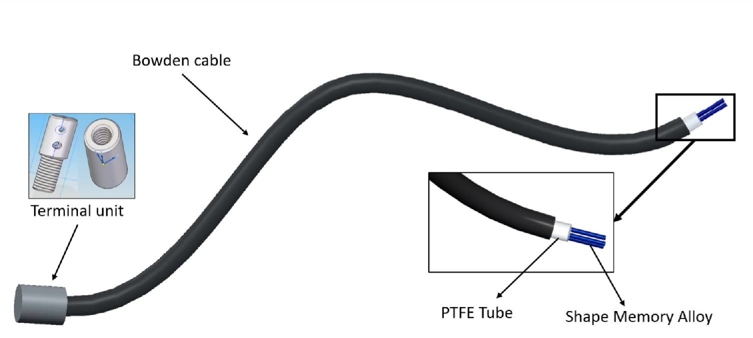
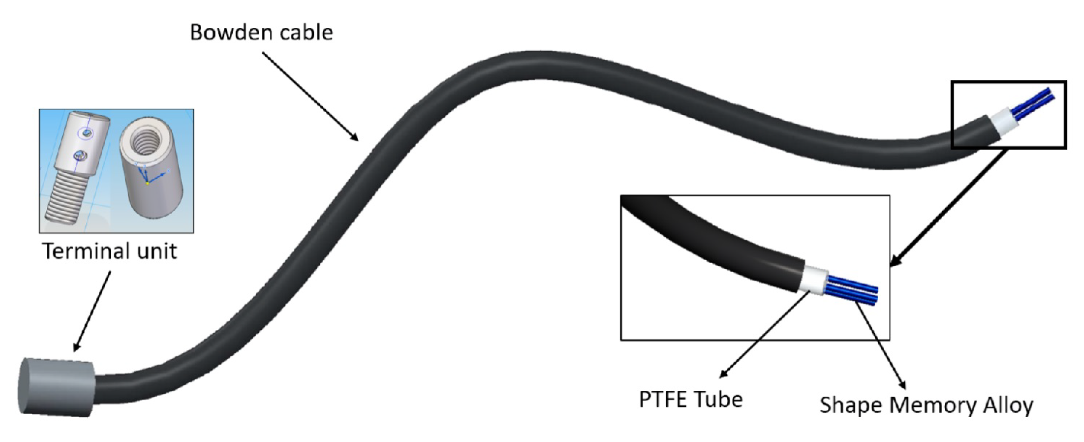
The SMA-based actuator presented in this work (Figure 2) is adapted from Villoslada et al. [8] and is composed by one or multiple SMAs wires, a Bowden cable which permits transmission of the force and helps to dissipate the heat, and PTFE tube. Additionally, to the end of the actuator are the terminal parts. All these are detailed below:
- the Bowden cable is a type of flexible tube (due to the forms of metal spiral) used to transmit mechanical force. This is covered with a protective nylon sheath. This Bowden cable help to guide the SMA actuators, transmit the force, and help to dissipate the heat which represents an advantage in the cooling stage.
- the PTFE tube is used as an electrical insulator between the Bowden cable and SMA wires. This presents certain features such as the ability to work at high temperatures, i.e., more than 250 C, and the possession of a low coefficient of friction.
- the terminal units are additionally used in the ends of the SMA wires. These are composed of two pieces that can be screwed to each other to set the tension of the SMA wires. The total SMA wire tension range adjustment is 0.01 m. These serve to connect the actuator to the actuated system in one end and, in the other one, to fix the SMA wires to the Bowden cable. Also, they serve as connectors for the power supply (using the control signal).
Thanks to the Bowden cable actuation, it is possible to bend the device. In this way, a flexible actuator is available that can be adapted to many applications, among its possible uses, that in soft robotics stands out.
In our approach, several SMA wires with different characteristics have been evaluated in terms of power consumption, cooling time, and dimensions, mounted in a simple configuration (only one SMA wire) or in parallel (in the case where various SMA wires are needed for high force). In this last case, various SMA wires can be mounted in parallel in the same Bowden cable or separately, each one in a Bowden cable. In both cases, when the SMA wires are in parallel configuration, an important characteristic is the tension of each SMA wire. Although the terminal units are used, these do not guarantee the same tension in each SMA wire. Compared to the case where only one SMA wire is controlled, in parallel configuration, various SMA wires (a sum of non-linear models with different force tensions) are controlled with a single controller. The different force tensions between SMA wires implicate that one SMA wire supports more force than other wires, and when these force differences are significant, it causes the actuator to break.
2.2. Test Bench
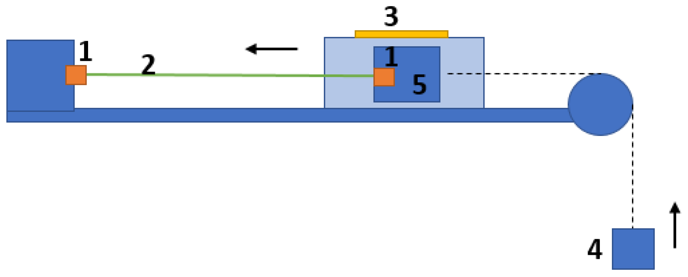
To test different configurations of the actuators, a test bench was built. The test bench allows multiple configurations for testing the SMA actuators: the SMA wire with a hanging mass attached to the non-fixed end, and the SMA wire with a bias spring attached to the non-fixed end, tests various wires in parallel configurations, adding external cooling system such air-flow and an agonistic–antagonistic actuation with two SMA actuators. A schematic diagram of the test bench part used in this work can be seen in the Figure 3, where the SMA actuator in the lineal movement can be tested. In Figure 3, 1 represents the points where the SMA actuators are attached, 2 represents the SMA actuator, 3 is the position sensor which measures the displacement of the movable part, 4 is a weight which will be moved by the actuator, and 5 is the movable part.
The method to fix the SMA wire or SMA-based flexible actuator (with the Bowden cable) is as follows: one of the ends of the SMA wire is fixed to the structure of the test bench and the other SMA ends is crimped to a movable part of the test bench. Over this movable part a magnetic strip on its top is fixed such as a part of the position sensor. When the wire contracts, the movable part is displaced, and the position sensor measures the displacement of the magnetic strip. In the movable part, a high-resistance polyethylene wire, Dyneema, from the Caperlan company was fixed, from where the dead weight or spring will be attached.
2.3. Electronic Hardware
To heat the SMA wire, which is necessary to activate its shape-memory effect and thus contract it, a controlled electric current is passed through the wire. This electric current is provided by a high-fidelity commutation circuitry, driving an extremely low resistance with a MOSFET transistor activated with a pulse width-modulated (PWM) signal from the microcontroller.
The electronic hardware used in the test bench is composed of:
- the power electronics, which is based on a MOSFET transistor (STMicroelectronics STP310N10F7, STMicroelectronics, Geneva, Switzerland), which, with the amplified PWM signal generated by the controller, opens and closes the circuit which is connected to the terminal units of the actuator.
- the controller, which is based on STM32F4 from STMicroelectronics®. This was fully programmed with Matlab/Simulink® [18]. Together with the power electronics, this can manage four distinct actuators.
- position sensors: for the linear movement, a NSE5310 with a resolution of m from amsAG company [19] was used, and for the antagonist–agonistic movement a Hall effect angular encoder (AS5045) with a resolution of 0.0879 degrees from amsAG company was used.
2.4. Control Strategy
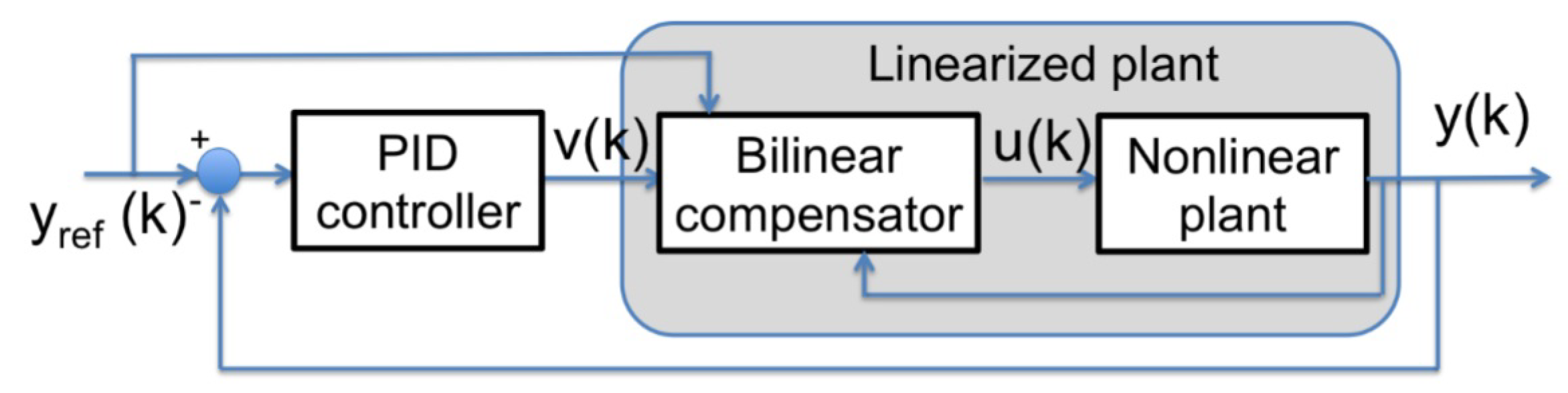
The main difficulty when controlling SMA-based materials is their saturated hysteretic behavior, which appears during martensite–austenite and austenite–martensite transformations. This introduces in the system non-linear behaviors, which makes it difficult to develop control algorithms for this type of actuator. In [20], a four-term Bilinear PID (BPID) control strategy was successfully applied to control a single SMA wire. Based on this work, a BPID controller with a bilinear compensator is proposed to control SMA actuators. The BPID controller is a combination of a standard linear PID controller cascaded with a bilinear compensator. The control scheme is shown in Figure 4. The architecture relies on the structure proposed by Martineau et al. [21]. The non-linearities of the plant limit the performance of the control loop and, applying this type of control architecture, an important advantage was obtained.
The BPID configuration represented in a continuous state-space such a single-input single-output (SISO) bilinear system is given by the following equations:
where is the state vector, is the input signal, A is a matrix of real values, b is an vector of real values, C is an vector of real values, and N is an matrix of real constants (comprising the bilinear coefficients) and is the output signal.
The discrete bilinear compensator that is introduced in the controller is:
where is the reference output at which the PID controller was tuned. This term compensates for the non-linearities of the plant. More information about how this formula is deduced can be found in [8,21].
The PID controller is used to generate the PWM signal which supplies the current to the actuator:
where is the PWM duty cycle, is the proportional gain, is the derivative gain and is the integral gain. is the error between the reference and the output.
The gains of the BPID controller were experimentally set by changing the gain values and observing the actuator response (trial and error method). The gains of the BPID are shown in Table 1.
2.5. Test Set-Up and Actuator Configurations
Different actuator configurations have been tested with the objective of choosing the adequate SMA-based actuator configuration according to the application where will be integrated. The actuators are based on wires with mm diameter (and in some cases mm), m length and all the tests are done at 20 C ambient temperature. The analysis is done according to the system response over step reference of 10,000 sensor units ( mm) and according to the control signal. The BPID parameters (Table 1) will be maintained throughout the experiments, independently of the SMA diameter, activation temperature, and actuator configuration (with Bowden cable or without Bowden cable). The position response over the SMA controller with the same , , , and gains will present a different response according to the plant dynamic (SMA actuator) where we can analyze the time response, and the controller signal giving the possibility to estimate the energy consumption of each actuator.
In the previous works, a SMA has been studied, modelling his hysteresis behavior with models based on Prandtl–Ishlinskii and Bouc–Wen, and the actuator with this controller such a black-box model based on NARX and Hammerstein–Wiener models [22,23].
However, many factors influence the performance of SMA-based actuators. In this work, some of these factors are tested:
- the performance of two types of SMA wires is studied. SMAs are highly sensitive to variations in material composition and thermomechanical treatments, and present different characteristics according the composition. In this sense, the behavior of the actuator has been compared using SMA wires at low and high activation temperature.
- the effect of the material of the Bowden cable sheath has been tested. The response of the SMA actuator with the Bowden cable and the response of the actuator without the Bowden cable have been compared.
- multiple SMA wires. If the actuator contains multiple SMA wires, it is necessary to decide between two different configurations: all SMA wires inside on single Bowden cable with PTFE tube or a Bowden cable with PTFE tube for each SMA wire. A simulation to study the thermal convection of the actuator has been performed using the Energy2D software [24].
On the other hand, the mechanical design of the actuator is one of the most important aspects on the actuator development. The actuator needs to be as compact and lightweight possible. For good operation, the SMA wire needs to be stretched such that when it begins to contract (a maximum 4% from its total length), moving the weight, it does not lose travel. In this context the Bowden cable is used, which offers the possibility to maintain the SMA wire stretch and the give the possibility of the actuator flexibility (one of the extremities is fixed to the Bowden cable) and different mechanical design was proposed to multiply the total displacement (double actuator and gearboxes presented in Section 3).
3. Results
This section presents comparison and analysis between different configurations of SMA-based actuators: with and without Bowden cable, high and low temperature, and independent or multiple SMA wires in the same Bowden cable. Three novel mechanical designs are proposed in Section 3.4, Section 3.5 and Section 3.6. With these new mechanical configurations, the total displacement or the energy consumption can be improved in some specific applications.
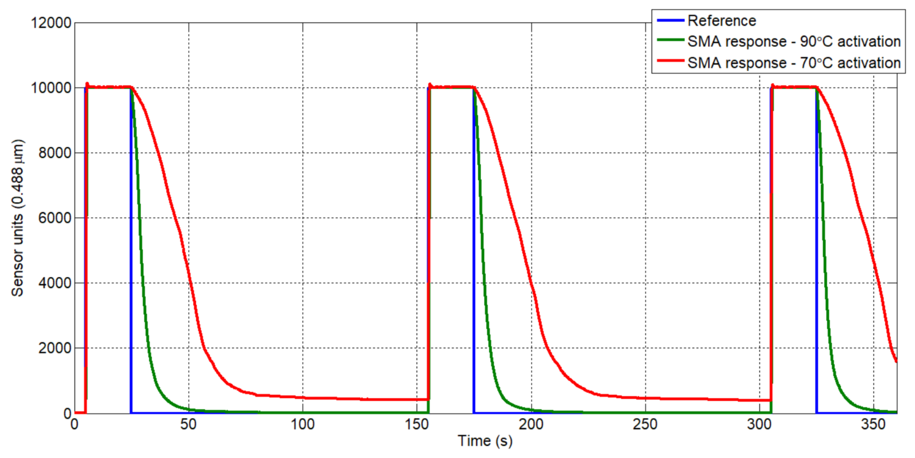
3.1. Actuator with 90 C Activation vs. Actuator with 70 C Activation
In this section, a comparison between two types of SMA wires-based actuator is presented. In the function of the ambient temperature environment, the candidate wires need to activate at more than 50 C, but the temperature difference between the ambient environment and the wire activation needs to be elevated to accelerate the heat exchange. Depending on the application, a high operating temperature can be a drawback. For example, SMA-based actuators have been used for robotic rehabilitation devices [25,26]; in these cases, a high temperature can cause incompatibilities. Between the candidate wires for the actuator are analyzed the wires with the activation temperature in 90 C (high temperature), alloys NiTi from Dynalloy Inc. Company [27], and wires with activation in 70–75 C (low temperature), alloys of NiTiCu from SAES Getters [28]. The Cu element added to the NiTi alloy, introduces a narrow hysteresis effect in the actuator behavior [29,30].
The experiment set-up is done in the SMA test bench with the wires of high and low temperature of 0.51 mm diameter. The force necessary to recuperate the initial shape in both cases is represented by one weight of 2 kg. The response of two actuators, with the same controller presented in Section 2.4, is show in the Figure 5.
As can be seen, in the cooling stage (“recuperation”) the low-temperature wire is much slower than the high-temperature wire. The thermal transfer between the wires and the ambient environment, from 90 C to ambient temperature and from 70 C to ambient temperature, affects the behavior of the actuators. In the first case, the temperature exchange is more accelerated due to the elevated temperature difference. This leads to a fast actuator “recuperation” and thus achieves set point. The low-temperature wire slows the actuator movement with approximately 20 s of delay compared with the actuator based on the high-temperature wire. Moreover, the low-temperature wire is not capable of recuperating the entire initial shape, resulting in an error presented in the permanent regime.
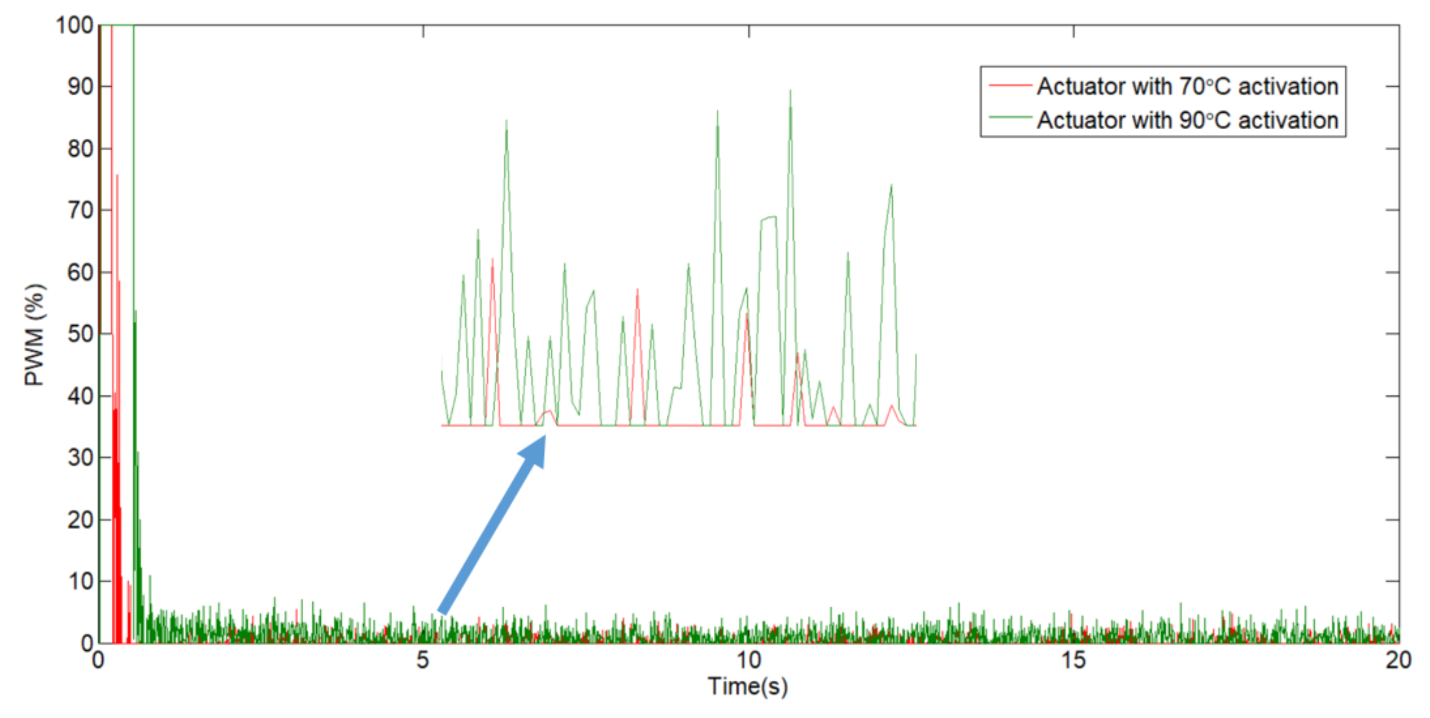
To calculate the exact power consumption, a current sensor can be placed in series with the actuator. The PWM signal is only trying to estimate the power consumption (the PWM signal is proportional to the current), but this estimation is not reliable due to the signal fluctuating. The PWM signals of the two actuators are compared in the Figure 6. The PWM signal area of the low-temperature wire is less than the area of the high-temperature wire, which implicate a lower energy consumption. This is largely due to the necessary temperature activation (lower) obtained with the Joule effect.
3.2. Simple vs. without Bowden Actuator—Activation with 90 C
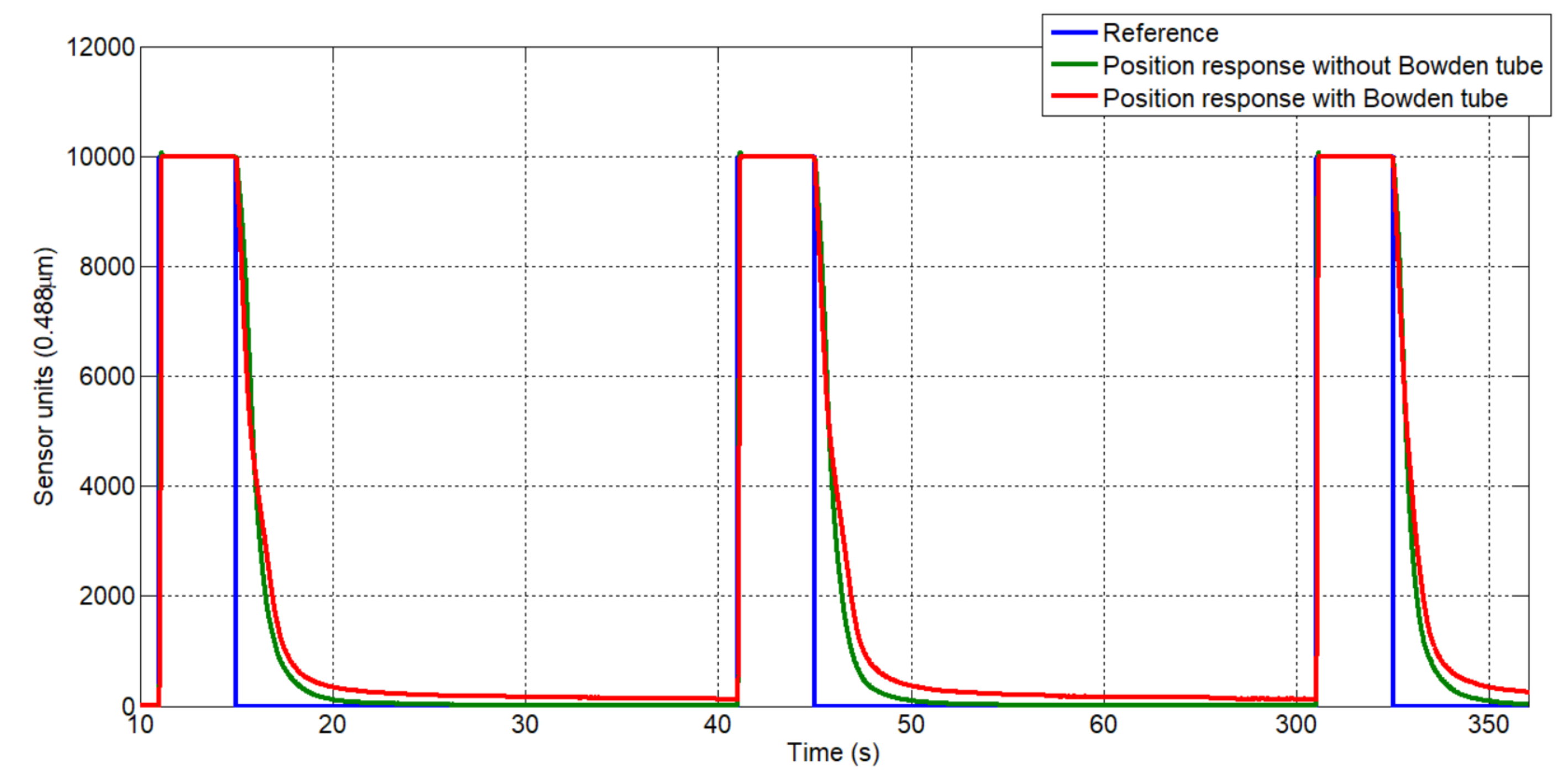
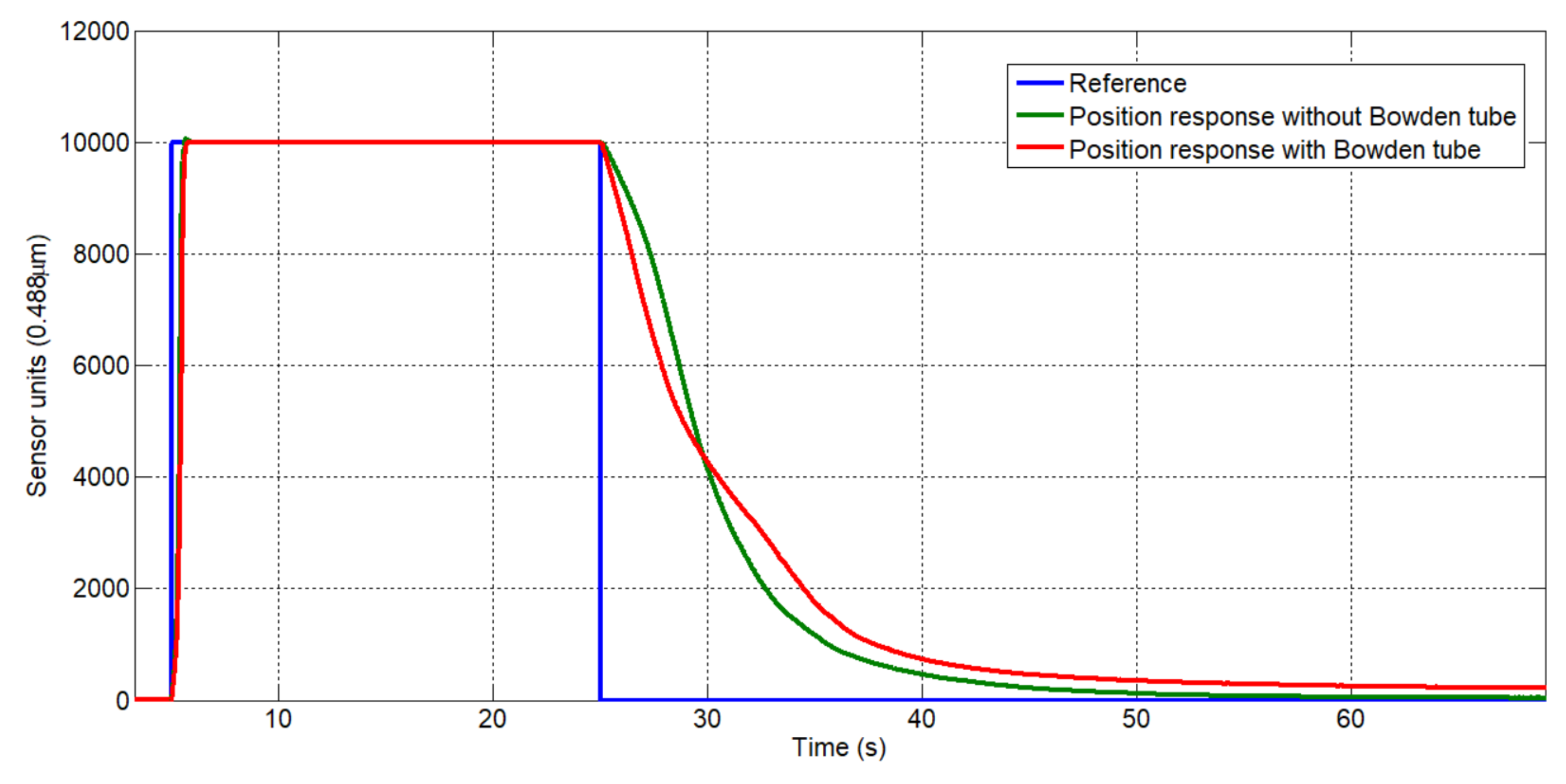
The simple actuator is based on SMA wire from the Dynalloy Inc. Company, which is introduced in the PTFE tube and everything in a Bowden cable. The diameter wire used in this experiment was 0.51 mm. In Figure 7 the response of the SMA actuator with the Bowden cable and the response of the actuator without the Bowden cable is presented, when the reference pattern is represented by a step reference with the amplitude of 10,000 units of sensor. With the same BPID controller parameters, the actuator responses are similar.
The actuator without Bowden cable in the heating stage presents a little overshoot compared with the second case when the SMA wire is introduced in the Bowden cable. This occurs due to the better heat dissipation effect when the SMA wire is in contact with the Bowden and PTFE tube. As a consequence of this effect, the actuator in the second case presents a slow response. The same effect is identified in the cooling stage, when the actuator “recuperates” the initial form. In this case, the Bowden cable helps the cooling stage of the SMA wire (Figure 8).
Figure 8 presents a zoomed part from Figure 7 to highlight the behavior of the two actuators in the heating and cooling stage. As can be seen, the Bowden cable affect in the cooling stage accelerates the actuator “recuperation”, and the heat is transmitted from the SMA wire to the Bowden cable, which aids the dissipation. This is observed in the first recuperation stage when the difference between the ambient environment and Bowden cable temperature is more elevated, and the heat exchange is more accelerated. In the second stage, when the temperature of the Bowden cable is nearer the ambient temperature, the SMA actuator without Bowden cable presents a better “recuperation”, the heat exchange going directly with the ambient environment. The Bowden cable in this stage maintains the temperature and slows the last stage of cooling for the SMA wire.
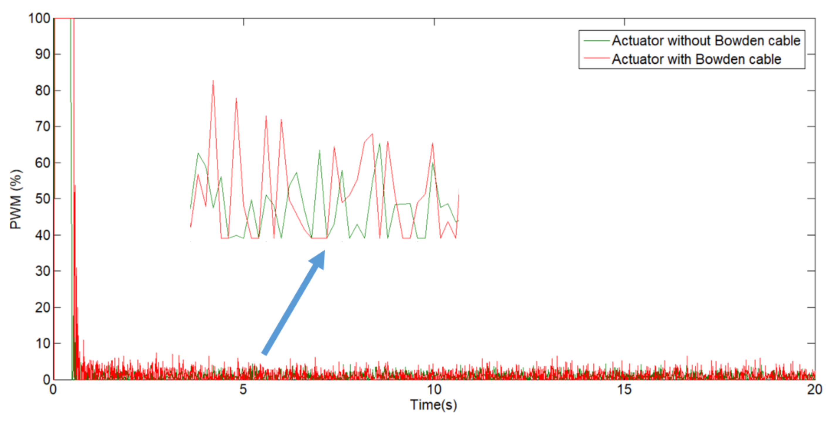
In practice, the control signal has a great importance which directly affects the dynamics of the system and, implicitly, its lifespan. A control signal that easily exceeds the system input or shows oscillating pulses between high values can cause severe damage to the system. The control signal responses of the two actuators with the same BPID controller parameters in front of the same reference (from Figure 7) can be seen in Figure 9.
Figure 9 presents the control signals of the two actuators following a step reference from 0 to 10,000 sensor units and maintaining this position for 20 s. The control signal is approximately the same with a little difference.
Depending on the area of the signals which doing with the axes system observe that the actuator with Bowden cable is little great compared without Bowden cable.
The control signal is directly proportional to the energy consumption, which means the actuator with the Bowden cable has a little more energy consumption compared to the actuator without Bowden cable.
3.3. Multiple SMA Wires Actuator
Another interesting configuration is the actuator with Bowden cable which contains multiples SMA wires. In this case, it is necessary to decide between two configurations: multiple SMA wires inside a single PTFE tube and Bowden cable or for each SMA wire independently a PTFE tube with Bowden cable. The first configuration, multiple SMA wires in parallel configuration in only one PTFE tube and Bowden cable presents some advantages compared with the second configuration:
- in only one Bowden cable, the total actuator size is more compact, the diameter being small;
- the SMAs wires are in contact, the thermal convention is better, and the power consumption is less;
- due to the thermal convention, the actuator movement is accelerated.
The disadvantage of this configuration can be observed in the cooling stage, where the heat dissipation is more slowly compared with the second configuration, which affect the actuator work frequency. This property has been analyzed in [25], and can be observed in Figure 10 where the Energy2D software [24] has been used to perform a thermal simulation of SMA actuator. The simulation was configured according to the SMA actuator parameters defining the dimensions, temperature coefficient, temperature of activation (reference temperature), thermal conductivity, specific heat, and density. In the simulation, two different configurations were analyzed: 3 SMA wires in only one Bowden cable and one SMA wire in a Bowden cable. In the first case, (Figure 10a), the 3 SMA wires have been heated for 20 s at 90 C, and cooled for 10 s (Figure 10b). In the second case, (Figure 10c,d), the process is similar but with only one SMA wire in a Bowden cable. Comparing the actuator behaviors in the cooling stage (Figure 10b,d), after 10 s, the 3 SMA wires in the same Bowden have a temperature of approximately 50 C and only one SMA wire in a Bowden cable has a temperature of approximately 30 C. At these temperatures, according to the Dynalloy datasheet [27], the actuator with three SMA wires has an approximately strain and only one wire has approximately strain, which implies that in the second case the heat is better dissipated.
According to the simulation, if the actuators are contracted at maximum force and displacement (4% of contraction) and after heating for 20 s, the external part of the Bowden cable has a temperature of approximately 60 C (Figure 10a).
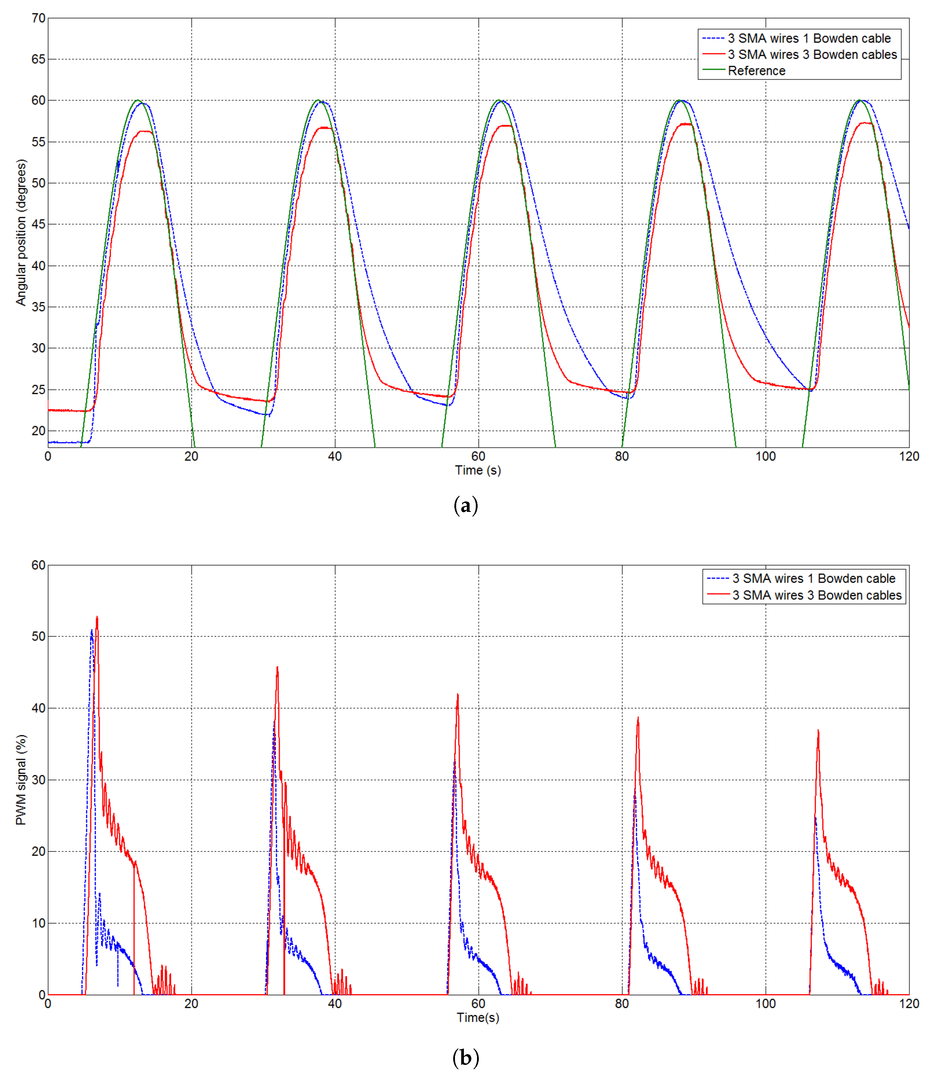
The same test with the two configurations was realized with real actuators. The results can been seen in Figure 11 where (a) presents the results of the two configurations (three SMA wires in three different Bowden cables and three SMA wires in only one Bowden cable, and (b) presents the PWM signals of the actuators. The two configurations were tested in a test bench capable of simulating the elbow joint of the human body for a person of 70 kg. The initial position of the elbow joint is 20 degrees, and the reference follows a sinusoidal pattern with a 30-degree amplitude and a 30-degree bias.
As can be seen in Figure 11a, the configuration with three Bowden cables has a slower response in the heating stage. This is caused by its better heat dissipation. This effect can also be observed in the cooling stage, where this configuration has a lower recovery time. After some cycles, the difference between both configurations in the cooling stage is more evident due to the heat accumulated in the Bowden cable.
The corresponding control signals, PWM currents, are given in Figure 11b. Although the peaks at the beginning are similar for both configurations (and the energy consumption, which is proportional to the PWM signal), the option with a single Bowden cable has a lower energy consumption during the displacement stage.
3.4. Simple vs. Double Actuator-Activation with 70 C
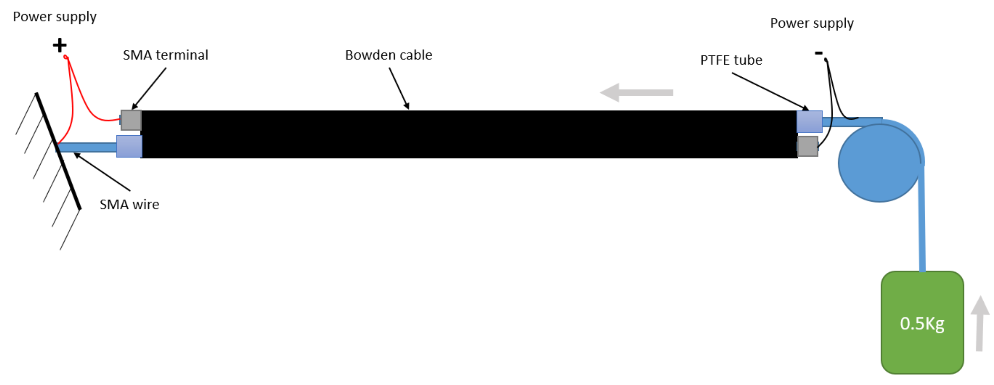
The double actuator is composed of two or more SMA wires (always an even number), each one on an individual PTFE tube and everything in one Bowden cable (Figure 12). One of the SMAs wires relates to one end to a fixed part and another end with a terminal which is fixed to the Bowden cable (SMA terminal). Another SMA relates to one end to the mobile weight, over which is actuated, and the other end is fixed to the other Bowden cable end. Both the SMA wires are connected to the power supply such as in Figure 12. Over the Joule effect, the SMAs wires contract and in the same time move the entry structure with the Bowden cable to the fixed part.
A SMA wire, in function of the Dynalloy datasheet, contracts 4% of the total length. This means, for the simple actuator, after the SMA wire is heated, the total displacement is:
and for double actuator in the same length:
where the is the total actuator length, is the length of each SMA wire from the double actuator, is the total displacement for the simple actuator, and is the total displacement resulted in the double actuator.
A simple actuator (Bowden cable with only one SMA wire) has a total displacement of 4% of the total length () according the datasheet of [27] (Equation (5)). The double actuator with a total length equal to the simple actuator () is composed of two SMA wires with dimensions of (to keep the same dimension with the simple actuator). The total displacement of the double actuator is the sum of the two SMA wire displacements: the first wire attached to a fixed part and to the Bowden terminal moves the Bowden tube, and the second one moves the mobile weight and at the same time will be displaced by the Bowden tube by the first wire. In this way, the total displacement (Equation (6)) will be .
Corresponding with Equations (5) and (6), with the same actuator length the double actuator presents a displacement of 1.9225 times more. On the other hand, the disadvantage of using this type of actuator compared with the simple actuator is to fix the extremity to a fixed structure (in the simple actuator the extremity of the SMA wire is fixed to the Bowden cable).
If the resistance of the simple actuator is , then the resistance of the double actuator can be calculated using the fowling expression:
where is the resistance of the double actuator.
The power absorbed by is:
and for double actuator:
where the is the power absorbed by the double actuator and the U is the power supply voltage. From Equations (8) and (9), it can be seen that the power absorbed by the double actuator is 2.0799 times greater than the simple actuator, but it obtains 1.9225 more displacement.
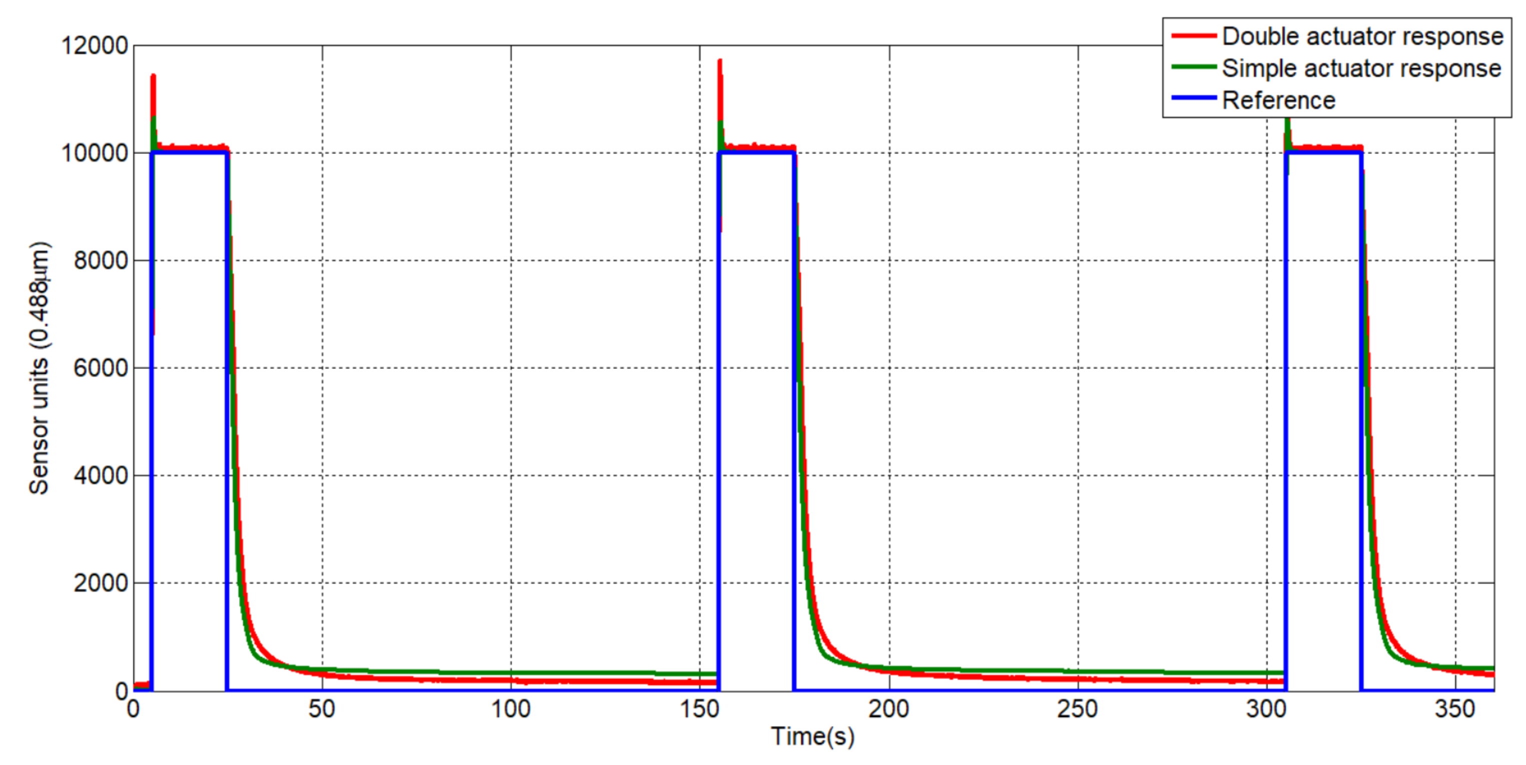
The displacement results and PWM control signal for the simple and double actuator are compared in the test bench. Due to the power electronic restrictions of the test bench presented in Section 2.2 the tests are done with 0.25 mm SMA wire diameter. The control parameters are the same presented in Section 2.4 and the length of the wires for the simple actuator is 0.2 m. For the double actuator, the wire dimensions are calculated in function of Equation (6). The recuperation force, in function of the wire diameter, is generated with 0.5 kg weight. The actuator position response to a step signal reference is presented in Figure 13.
In the heating stage, the actuator’s response is relatively similar, with the actuators presenting overshoot. Compared with the response of the actuators based on 0.51 mm SMA wire presented in the previous sections, overshoot is presented, representing a small electrical power consumption and the necessity to recalibrate the BPID controller parameters. In the first half of actuator cooling stage, the double actuator presents a small delay in the last part, due to entry in the martensite zone before the simple actuator.
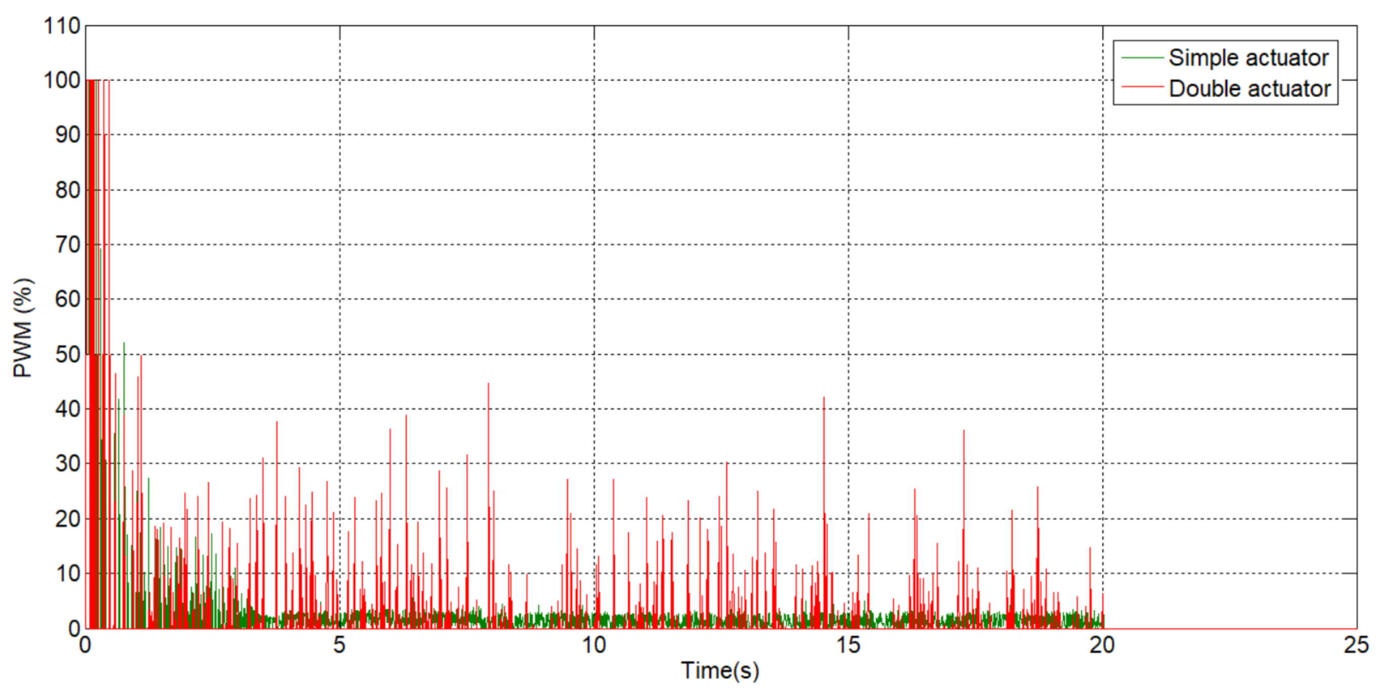
The PWM control signals of both actuators is presented in Figure 14. As can be seen, the PWM controller signal generated by the double actuator presents a relatively high peak compared with the PWM signals of the simple actuator. These high peaks can be cancelled by recalibrating the BPID controller.
From Figure 14 it is difficult to say if the simple actuator is electrically more efficient than the double actuator, due to the big differences between the generated signals by the controller. The simple actuator PWM signal presents an amplitude which oscillates in a small range during the actuation, compared with the double actuator. In this sense the average of the PWM control signals was calculated, which is 2.0696% for the simple actuator and 2.2283% for the double actuator, representing a relatively similar power consumption. However, this result depends on the BPID parameters, the desired reference and the actuation force. In this case, the PWM signal average is not reliable. Also, this signal presented in Figure 14 is not adequate for the actuator control; a signal of this type shortens the actuator life (in general, a soft signal can be used). In certain cases, it is probable that double actuators have less power consumption than simple actuators, considering that the need to heat is less in the simple actuator to reach the desired reference.
3.5. Gear Box 1:4
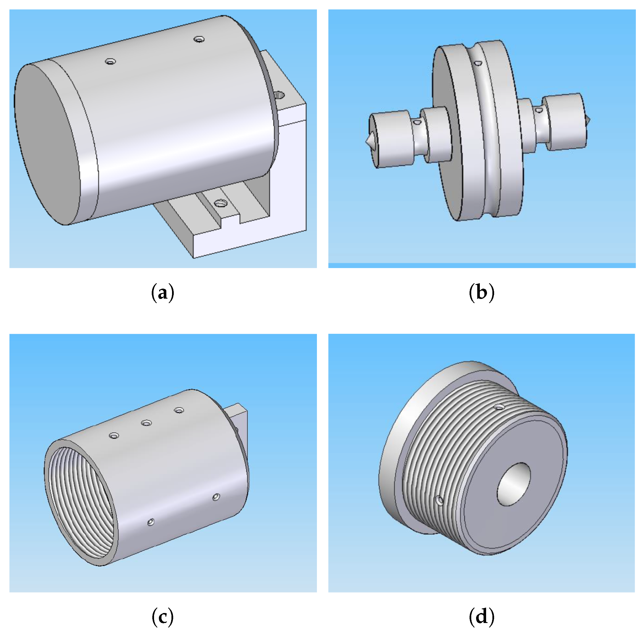
A gearbox with 1:4 relation is proposed for multiplication of the total wire displacement. The gear is designed to permit the output force of approximately 116 N, and multiply the displacement of the actuator 4 times. According to these requirements, the proposed gearbox is composed of the gear unit, the housing unit, and the cover unit Figure 15.
The gear unit is composed of three pulleys: two pulleys for the input movement where the SMA wires can be mounted (from one to five in each one) and the output movement pulley, where one cable is mounted for the output displacement. The input pulleys present a rounded channel where the SMA wires roll. It is important that the distance between the housing wall and the pulleys be less than the diameter wire, otherwise the wire goes out from the channel and can create jams. The wires relate to the pulleys with the aid of set screws. The diameter of the input pulleys is mm. The output pulley is similar to the input pulleys and presents a channel with a wire (can be nylon) which is rolled in the opposite sense and is fixed with a set screw. The diameter of this pulley is mm.
The proposed gearbox has the input pulleys with the input radio, mm, and the output pulley mm. The multiplication displacement obtained can be calculated according to the pulley’s radius . According to this relation, for 116 N output force and 0.0628 m of displacement, 12 SMA wires with lengths of 0.3875 m are necessary.
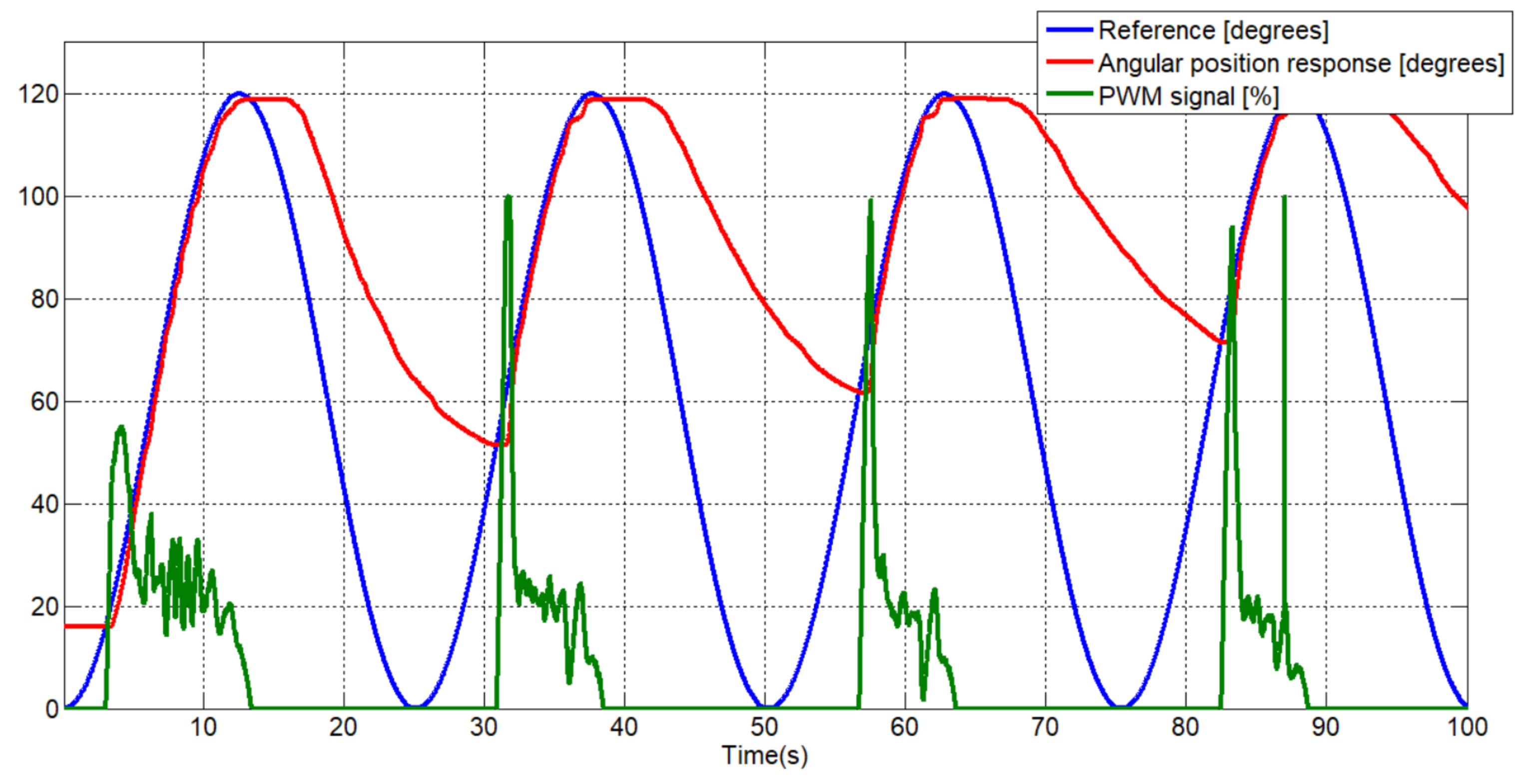
To test the gearbox, three SMA wires with the diameter of 0.51 mm were mounted in each input pulley, and a Nylon wire to the output pulley. The response of the actuator to a sine reference and the PWM control signal can be seen in the Figure 16.
The actuator response with a gearbox 1:4 in the cooling stage presents a delayed response compared with other configurations. This delayed response is due to the cooling deformation force applied to the SMA actuator, and the movement range of the SMA wires (around the martensite zone). To avoid these inconveniences, the initial position can be recuperated with more weight in the cooling stage and for the last inconvenience a possible solution is to mount long-length wires, avoiding working in the martensite zone.
3.6. Brake Gear 1:6 Actuator
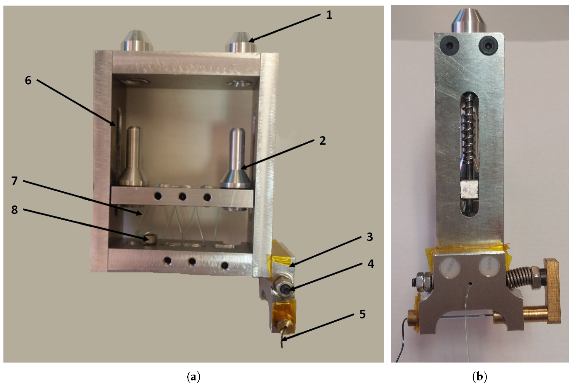
The brake gear 1:6 offers the possibility to multiply the displacement of SMA actuators six times, but it can be easily configured for different relations (less—with the actual components, higher—some components need to be fabricated). This gear presents one brake, which can be activated to maintain a fixed position or to control the initial shape recovering stage (after the SMA wires are cooled) with low power-supply consumption. Figure 17 presents the proposed actuator with the brake.
In Figure 17 the brake actuator with the output displacement multiplied 1:6 times is presented. In the left part is a front view of the actuator, where: 1—the terminal part where the SMAs wires are fixed, 2—the terminal part for the Bowden tube (this part is mobile), 3—the brake, 4—a mobile axis which presents in the middle a hole from where the output cable passes, 5—is one SMA wire which actuates the brake, 6—the axis displacement for the mobile part, 7—the output cable, and 8—the point where the output cable is fixed. The output cable gives the multiplied movement.
The SMA wires are fixed in the actuator terminal and to the other extremity to the Bowden cable. In each Bowden cable up to five SMA wires (limited according to the Bowden diameter) can be mounted, but there must be always the same number of SMAs in each Bowden cable, for the force equilibrium. In the heating stage, the SMA wires actuate over the mobile part of the actuator, producing the displacement of the output wire (nylon wire) over the pulleys. The actuator presents six pulleys, each one with a middle channel from the output wire pass. The distance between the pulley walls is less than the output wire diameter, avoiding going to and from the channel and produce jams. The output pulleys of the mobile part coincide perpendicularly with the output pulleys of the fixed part. According to this, each pulley multiplied the displacement by two. Changing the number of pulleys, the multiplication rate easy can be modified. The current configuration permits mounting 10 SMA wires which give a total force around 356 N. The output actuator force with this configuration is 59.3 N.
One of the actual limitations of the SMA-based actuators is the electrical power consumption when this is actuated by the Joule effect. The proposed actuator presents a brake which maintains a certain position, blocking the output wire. The brake can be seen in the Figure 17b. This is composed of a fixed part, attached to the actuator and electrically isolated, and a mobile part which is actuated with a SMA wire with a length of 0.025 m. The fixed part has two holes which, when the mobile part is actuated, are aligned with the hole of the mobile part and passes the output wire. Without actuation, the mobile part recuperates the position (closing the pass of the output wire) with the aid of a compressing spring. In function of this when the mobile part is not actuated by the output wire is blocked, maintaining the current position and reducing the electrical power consumption to 0. Other advantages are the possibility of cooling the actuators when maintaining a fixed position and to control the output position of the actuator in the initial shape recuperation stage with the aid of the brake.
4. Discussion
Actuators are one of the most important part from one actuated system. The most common actuators in mechatronics systems are DC motors in mobile systems due to the possibility to aliment them from the battery and due the easy ability to control them, and AC motors are preferred when the system must be easy to connect to the electrical grid (most common in the static devices). On the other hand, pneumatic systems which offer a faster response but cannot carry high force and need an air compressor, or hydraulic actuators which offer a high force but provide a rather slower system using fluids and need a compressor, were integrated in various systems.
Stepper motors are good for the position control at low velocity; instead, brushless DC motors are indicated where a high velocity is needed; in general, these are used together with the gearboxes to reduce the velocity and increase the torque.
In the development of new systems a compact mechanical design is often required, with lightweight, noiseless operation. All of this is closely related with the actuator, and in this context new solutions are being sought in emerging actuation systems such actuators based on SMA.
According to the results presented in Section 3, the SMA-based actuators can be a good candidate to replace conventional actuators in certain applications. These present a good relation force/weight, noiseless operation, have a low frequency of work (no gears are necessary) and are relatively low cost compared with other conventional actuators.
The material and the mechanical design is an important factor when a SMA-based actuator is developed for a certain application. These characteristics influence the work frequency, electrical consumption, and the total movement length; for example a SMA wire with high-temperature activation presents a faster work frequency but the power consumption is more elevated compared with a low-temperature activation SMA actuator. Furthermore, the mechanical design gives the possibility of flexibility to the actuator or to multiplicate the displacement (such as in the case of the double actuator and gear presented in Section 3), which is a good option for applications such biomedicine, the automotive industry, robotics, and soft robotics, etc. On the other hand, the majority of SMAs based on NiTi alloy only contracts 4% of the total length, which offers a limited displacement. With the objective to increase this displacement and the total force, different mechanical designs can be addressed such as presented in Section 3. Some of the principal characteristics according to the results will be detailed further:
- in applications where the total SMA-based actuator force is necessary to increase, this can be done with multiple SMA wires which can be actuated in parallel configuration. In terms of energy consumption, the multiple SMA wires in only one Bowden is more reduced than each SMA in individual Bowden. Also, the SMA wires in the same Bowden cable can be adjusted at the same tension more precisely, avoiding wire breaks. Instead, the SMA wires in separate Bowden cables offer a better heat exchange with the ambient temperature.
- the total displacement of the SMA-based actuator proposed in this work can be almost doubled (for the same actuator length) using the double actuator configuration presented in Section 3. The disadvantage of this configuration is that the two extremities of the actuator need to be fixed and permit the Bowden cable displacement.
- different mechanical designs can be combined with the SMA-based actuator to multiply the displacement (gear 1:4 and brake gear 1:6). These configurations are more complex but can multiply the total displacement of the actuator. Mainly, the brake gear 1:6 can be configured easily to multiply the displacement with different ratios, in a compact design and give the possibility to reduce drastically the power consumption when the actuator maintains the braking position in the system with a second actuator of low energy consumption.
Compared to the literature, this paper, in addition to the new configurations such as double actuator or brake actuator, presents an analysis of different configurations of SMA actuators, with the goal to provide the reader with the opportunity to choose the adequate configuration of SMA actuators according to the application in which it will be integrated. Compared with other actuators which multiply the SMA displacement, the actuator mechanical design is proposed for large forces (more than 100 N from various wires in parallel), with a compact and flexible design (less the multiplication mechanism part).
The SMA-based actuators can be considered a good alternative to the conventional actuators in applications where lightweight, noiseless operation, low speed (without gearboxes), and relatively low cost is necessary. The analysis and different mechanical configuration presented in Section 3 offer the possibility to choose the adequate configuration of the actuator based on SMA, which can be better adapted to a specific application.
5. Conclusions
Different configurations of SMA-based actuators have been proposed, tested, and analyzed with the objective to determine the most effective configuration such an alternative solutions to the conventional actuators to be integrated in different applications.
The Bowden cable configuration offers the possibility of flexibility for the actuator which easy can be integrated in applications such as robotics and soft robotics, medicine, aerospace, etc. Also, the Bowden cable offers the possibility to unite various SMA wires in parallel configuration to increase the actuation force (the SMA wires in the same Bowden cable is more electrically efficient and it is easier to adjust the same tension, but the cooling stage is slower).
The SMA thickness and activation temperature, which are defined according to the alloy percentage, define the actuator work frequency. In robotics applications, NiTi alloy with activation in C usually is used, due to the heat fast exchange with ambient temperature. More than C high activation temperature, makes the insulation process difficult and activation temperatures lower than C slow the actuator work frequency.
Different mechanical configurations have been presented to increase the electrical efficiency and the total displacement work. The brake gear 1:6 actuator offers the possibility of configuration of the multiplication ratio, and maintains the actuator in a fixed position with a low energy consumption (with the brake aid).
Author Contributions
D.B. and L.E.M. has overseen project administration and funding acquisition. D.-S.C. developed the SMA actuators and carried out the experiments. L.E.M. has collaborated in actuators development and supervised the research. D.-S.C. and D.B. wrote the manuscript. All the authors read and approved the final manuscript.
Funding
The research leading to these results has received funding from the Exoesqueleto para Diagnostico y Asistencia en Tareas de Manipulación (DPI2016-75346-R) Spanish research project and from RoboCity2030-DIH-CM, Madrid Robotics Digital Innovation Hub, S2018/NMT-4331, funded by “Programas de Actividades I+D en la Comunidad de Madrid” and cofunded by Structural Funds of the EU.
Acknowledgments
The authors like to thank to the “TERAS, ROBOTIC TECHNOLOGIES APPLIED TO HEALTH S.L.” for the interest shown in the results of this investigation.
Conflicts of Interest
The authors declare no conflict of interest.
References
- Jani, J.M.; Leary, M.; Subic, A.; Gibson, M.A. A review of shape memory alloy research, applications and opportunities. Mater. Des. (1980–2015) 2014, 56, 1078–1113. [Google Scholar] [CrossRef]
- Hartl, D.J.; Lagoudas, D.C. Aerospace applications of shape memory alloys. Proc. Inst. Mech. Eng. Part G J. Aerosp. Eng. 2007, 221, 535–552. [Google Scholar] [CrossRef] [Green Version]
- Chau, E.; Friend, C.; Allen, D.; Hora, J.; Webster, J. A technical and economic appraisal of shape memory alloys for aerospace applications. Mater. Sci. Eng. A 2006, 438, 589–592. [Google Scholar] [CrossRef]
- Butera, F.; Coda, A.; Vergani, G.; SpA, S.G. Shape memory actuators for automotive applications. In Nanotec IT Newsletter; Airi/Nanotec IT: Roma, Italy, 2007; pp. 12–16. [Google Scholar]
- Stoeckel, D. Shape memory actuators for automotive applications. Mater. Des. 1990, 11, 302–307. [Google Scholar] [CrossRef]
- Morgan, N. Medical shape memory alloy applications—The market and its products. Mater. Sci. Eng. A 2004, 378, 16–23. [Google Scholar] [CrossRef]
- Sreekumar, M.; Nagarajan, T.; Singaperumal, M.; Zoppi, M.; Molfino, R. Critical review of current trends in shape memory alloy actuators for intelligent robots. Ind. Robot. Int. J. 2007, 34, 285–294. [Google Scholar] [CrossRef]
- Villoslada, A.; Flores, A.; Copaci, D.; Blanco, D.; Moreno, L. High-displacement flexible Shape Memory Alloy actuator for soft wearable robots. Robot. Auton. Syst. 2015, 73, 91–101. [Google Scholar] [CrossRef]
- Copaci, D. Non-Linear Actuators and Simulation Tools for Rehabilitation Devices. Ph.D. Thesis, Carlos III University of Madrid, Madrid, Spain, 2017. [Google Scholar]
- Rao, A.; Srinivasa, A.R.; Reddy, J.N. Design of Shape Memory Alloy (SMA) Actuators; Springer: Berlin, Germany, 2015; Volume 3. [Google Scholar]
- Reynaerts, D.; Van Brussel, H. Design aspects of shape memory actuators. Mechatronics 1998, 8, 635–656. [Google Scholar] [CrossRef]
- Nizamani, A.M.; Daudpoto, J.; Nizamani, M.A. Development of Faster SMA Actuators. In Shape Memory Alloys: Fundamentals and Applications; IntechOpen: London, UK, 2017; p. 105. [Google Scholar]
- Mosley, M.; Mavroidis, C.; Pfeiffer, C. Design and dynamics of a shape memory alloy wire bundle actuator. In Proceedings of the ANS, 8th Topical Meeting on Robotics and Remote Systems, Pittsburgh, PA, USA, 25–29 April 1999; pp. 1–14. [Google Scholar]
- Gummin, M.A.; Donakowski, W.; Gaines, G. Shape Memory Alloy Actuators. U.S. Patent 7,256,518, 14 August 2007. [Google Scholar]
- Elwaleed, A.K.; Mohamed, N.A.; Nor, M.J.M.; Mustafa, M.M. A new concept of a linear smart actuator. Sens. Actuators A Phys. 2007, 135, 244–249. [Google Scholar] [CrossRef]
- Pittaccio, S.; Viscuso, S.; Rossini, M.; Magoni, L.; Pirovano, S.; Villa, E.; Besseghini, S.; Molteni, F. SHADE: A shape-memory-activated device promoting ankle dorsiflexion. J. Mater. Eng. Perform. 2009, 18, 824–830. [Google Scholar] [CrossRef]
- Leng, J.; Yan, X.; Zhang, X.; Huang, D.; Gao, Z. Design of a novel flexible shape memory alloy actuator with multilayer tubular structure for easy integration into a confined space. Smart Mater. Struct. 2016, 25, 025007. [Google Scholar] [CrossRef]
- Caballero, A.F.; Copaci, D.S.; Peciña, Á.V.; Rojas, D.B.; Lorente, L.M. Sistema Avanzado de Protipado Rápido para Control en la Educación en Ingeniería para grupos Multidisciplinares. Rev. Iberoam. Autom. Inform. Ind. RIAI 2016, 13, 350–362. [Google Scholar] [CrossRef]
- amsAG. amsAG. Available online: https://ams.com (accessed on 18 May 2019).
- Villoslada, Á.; Escudero, N.; Martín, F.; Flores, A.; Rivera, C.; Collado, M.; Moreno, L. Position control of a shape memory alloy actuator using a four-term bilinear PID controller. Sens. Actuators A Phys. 2015, 236, 257–272. [Google Scholar] [CrossRef] [Green Version]
- Martineau, S.; Burnham, K.; Minihan, J.; Marcroft, S.; Andrews, G.; Heeley, A. Application of a bilinear PID compensator to an industrial furnace. IFAC Proc. Vol. 2002, 35, 25–30. [Google Scholar] [CrossRef]
- Martín Clemente, A.I. Modelado y Control de Sistemas no Lineales de Tipo SMA. Ph.D. Thesis, Universidad Carlos III de Madrid, Madrid, Spain, 2013. [Google Scholar]
- Copaci, D.; Villoslada, A.; Blanco, D. Modelado y simulación de actuadores SMA con carga variable. In Proceedings of the XXXVI Jornadas de Automática, Bilbao, Spain, 2–4 September 2015. [Google Scholar]
- Xie, C. Interactive Heat Transfer Simulations for Everyone. Phys. Teach. 2012, 50, 237–240. [Google Scholar] [CrossRef]
- Copaci, D.; Martín, F.; Moreno, L.; Blanco, D. SMA Based Elbow Exoskeleton for Rehabilitation Therapy and Patient Evaluation. IEEE Access 2019, 7, 31473–31484. [Google Scholar] [CrossRef]
- Serrano, D.; Copaci, D.; Moreno, L.; Blanco, D. SMA based wrist exoskeleton for rehabilitation therapy*. In Proceedings of the 2018 IEEE/RSJ International Conference on Intelligent Robots and Systems (IROS), Madrid, Spain, 1–5 October 2018; pp. 2318–2323. [Google Scholar] [CrossRef]
- Dynalloy. Dynalloy, Inc. Makers of Dynamic Alloys. Available online: http://www.dynalloy.com/tech_data_wire.php (accessed on 18 May 2019).
- SAES Getters. Available online: http://www.memry.com/products-services/melting/nitinol-alloys (accessed on 18 May 2019).
- Nespoli, A.; Passaretti, F.; Villa, E. Phase transition and mechanical damping properties: A DMTA study of NiTiCu shape memory alloys. Intermetallics 2013, 32, 394–400. [Google Scholar] [CrossRef]
- Jiang, S.; Sun, D.; Zhang, Y.; Hu, L. Deformation Behavior and Microstructure Evolution of NiTiCu Shape Memory Alloy Subjected to Plastic Deformation at High Temperatures. Metals 2017, 7, 294. [Google Scholar] [CrossRef]
Figure 1.
Different SMA-based actuator configurations. (a) Arrangement of SMA wires on end plate [13]; (b) MigaOnev SMA linear actuator [14].

Figure 2.
Flexible SMA-based actuator.

Figure 3.
Test bench for SMA actuators

Figure 4.
BPID controller scheme BPID control scheme [8] (taken and adapted from [21]). is the reference, is the position sensor signal, is the control signal generated by the PID controller and the is the control signal rectified by the bilinear term.

Figure 5.
SMA actuator response: high temperature vs. low temperature.

Figure 6.
Actuator PWM signals with activation in 90 C respectively 70 C.

Figure 7.
SMA of 0.51 mm diameter position response with Bowden cable vs. without Bowden cable.

Figure 8.
SMA actuator with Bowden cable vs. without Bowden cable (Figure 7 enlarged).
Figure 8.
SMA actuator with Bowden cable vs. without Bowden cable (Figure 7 enlarged).

Figure 9.
Actuator PWM signals with Bowden and without Bowden cable.

Figure 10.
Simulation of thermal convection of two SMA-based actuators configuration [25] where: 1—SMA wires, 2—PTFE tube, 3—Metal part of the Bowden cable, 4—Nylon part of the Bowden cable (a) heating stage of three SMA wires actuator during 20 s, (b) cooling stage for 10 s after 20 s of heating stage, (c) heating stage of one SMA wire actuator during 20 s, (d) cooling stage for 10 s after 20 s of heating stage.

Figure 11.
Multiple SMA wires actuator. (a) SMA based actuator position response, (b) PWM signals corresponding to SMA based actuator response.
Figure 11.
Multiple SMA wires actuator. (a) SMA based actuator position response, (b) PWM signals corresponding to SMA based actuator response.

Figure 12.
Double actuator configuration.

Figure 13.
SMA double vs. simple actuators response.

Figure 14.
PWM control signal for double vs. simple actuator.

Figure 15.
Gearbox 1:4 structure components. (a) Gear 1:4; (b) Gear unit pulleys; (c) Gear housing; (d) Gear cover.
Figure 15.
Gearbox 1:4 structure components. (a) Gear 1:4; (b) Gear unit pulleys; (c) Gear housing; (d) Gear cover.

Figure 16.
SMA-based actuator with gear 1:4 response.

Figure 17.
Brake gear 1:6 actuator. (a) Front view; (b) Lateral view.


Table 1.
BPID Controller gains.
| Gain | Kp | Kd | Ki | Kb |
|---|---|---|---|---|
| Value | 0.24 | 0.018 | 0 | 1 |
© 2019 by the authors. Licensee MDPI, Basel, Switzerland. This article is an open access article distributed under the terms and conditions of the Creative Commons Attribution (CC BY) license (http://creativecommons.org/licenses/by/4.0/).
Share and Cite
MDPI and ACS Style
Copaci, D.; Blanco, D.; Moreno, L.E. Flexible Shape-Memory Alloy-Based Actuator: Mechanical Design Optimization According to Application. Actuators 2019, 8, 63. https://doi.org/10.3390/act8030063
AMA Style
Copaci D, Blanco D, Moreno LE. Flexible Shape-Memory Alloy-Based Actuator: Mechanical Design Optimization According to Application. Actuators. 2019; 8(3):63. https://doi.org/10.3390/act8030063
Chicago/Turabian StyleCopaci, Dorin, Dolores Blanco, and Luis E. Moreno. 2019. "Flexible Shape-Memory Alloy-Based Actuator: Mechanical Design Optimization According to Application" Actuators 8, no. 3: 63. https://doi.org/10.3390/act8030063
Note that from the first issue of 2016, this journal uses article numbers instead of page numbers. See further details here.