Design and Analysis of a Clutched Parallel Elastic Actuator
by
 , , , and
Bernhard Penzlin
1,* ,
,
Mustafa Enes Fincan
1,
Yinbo Li
2,
Linhong Ji
2,
Steffen Leonhardt
1 and
Chuong Ngo
1 1
Chair for Medical Information Technology, Helmholtz Institute, RWTH Aachen University, Pauwelsstr. 20, D-52074 Aachen, Germany
2
Institute of Mechanical Design, Department of Mechanical Engineering, Tsinghua University, Shuangqing Road 30, Beijing 100084, China
*
Author to whom correspondence should be addressed.
Actuators 2019, 8(3), 67; https://doi.org/10.3390/act8030067
Submission received: 24 July 2019
/
Revised: 30 August 2019
/
Accepted: 3 September 2019
/
Published: 5 September 2019
(This article belongs to the Special Issue Variable Stiffness Actuators)
Abstract
:Various actuator topologies are discussed for the purpose of powering periodic processes and particularly walking robots. The Clutched Parallel Elastic Actuator (CPEA) is proposed to reduce the energy consumption of active exoskeletons. A nonlinear model of the CPEA is presented in addition to the mechanical design. The CPEA prototype is operated with a passive load on the walking trajectory of the hip joint. The actuator is controlled with a cascaded position control and a superimposed Iterative Learning Controller (ILC). The controller was chosen to ensure comparability between active and deactivated spring operation. The application of the CPEA has the potential to increase efficiency in the design of exoskeletons.
1. Introduction
The use of compliant actuators is often associated with safe human–machine interaction, the reduction of peak torque, peak power, and energy consumption [1,2,3]. Actuators with additional elasticity activatable via a clutch, as an extension of the actuators with constant, permanently-engaged springs, are moving into focus [4]. Various approaches for using parallel elastic actuators (PEAs) have been introduced. Minimizing power consumption for the performance of periodic tasks is of great interest. A possible option for this is the addition of Parallel Elasticities (PEs). This applies generally to robots and particularly to all automated applications where a proper torque-angle profile is to be achieved. It was shown in an experiment with a Clutched PEA (CPEA) for use on a robot that the efficiency of the drive can be increased by 55%, whereby the comparison system recuperates the energy electrically [5]. The application of PEAs in prosthetics has already proven successful with prototypes. The interaction between human and machine can be improved by optimizing the stiffness and foot alignment to the walking situation [6]. Grimmer et al. showed in a simulation study that the energy consumption and the peak power are reduced by a PEA for the ankle joint over a range between 0.5 m/s and 2.6 m/s [7].
Furthermore, there are prototypes including a PE that support the knee [8]. Liu et al. developed a switching PEA, where the PE is activated in the stance phase to recycle energy and support the body weight, especially for the stance phase of robot legs during running. The actuator is designed for the knee, and it is not a motion support system for humans [9]. A PEA for the hip was also presented for force enhancement and support in industrial applications [10]. The PEAs are particularly interesting for active orthoses and exoskeletons of the lower limb, since the most important task, the upright gait, is a periodic process. It has been demonstrated simulatively that the Root Mean Squared (RMS) power consumption can be reduced by up to 61% by the insertion of PEs. At the same time, the drive torque provided by the active part of the actuator decreases by up to 66% [11]. This can result in smaller actuators and batteries. There are further independent experimental results confirming the reduction of energy consumption by PEs during gait [12,13].
A disadvantage of the PEA is that it can have a negative effect on the energy requirement in the case of a non-cyclical positioning task. This can be bypassed by the switchable deactivation of the elasticity or by a dynamic adjustment of the equilibrium point [14].
It is important for the design of an actuator to know which torques and speeds are to be assumed. Maximum torques for the knee, normalized with the subject’s weight, are set to 0.86 Nm/kg at a gait speed of 1.6 m/s [15]. The maximum normalized knee torque at gait speeds of around 1.2 m/s is 0.38 Nm/kg–0.56 Nm/kg depending on the posture. Under the same conditions, the normalized hip torque varies from 0.82–0.94 Nm/kg [16]. Actuators for hip support have been developed elsewhere [17,18,19,20,21,22,23]. Table 1 summarizes the existing design for hip actuators, including PEA, RA (Rigid Actuator), SEA (Serial Elastic Actuator), cRSEA (clutched Rigid Series Elastic Actuator), and MAACEPA. In the summary, the torque at 100% support is between 18 Nm and 68.6 Nm, and the nominal velocity is between 25 rpm and 84.7 rpm. So far, no actuator prototype has been published that is designed as a CPEA for full support in hip rehabilitation.
An actuator is presented in this paper that has been designed for the hip joint of an exoskeleton or active orthosis. The hypothesis of this paper is that energy demand and peak load values can be reduced by using a PEA at the hip. The second section of this paper presents the CPEA with its functional structure, a model, and the prototype developed. In the third section, the actuator control including cascaded and iterative learning control are explained. In the fourth section, the procedure for the experimental validation for a step response and gait trajectories of the hip is presented. Subsequently, the experimental results are discussed. The paper closes with a conclusion.
2. Mechanical Design
2.1. Technical Requirements
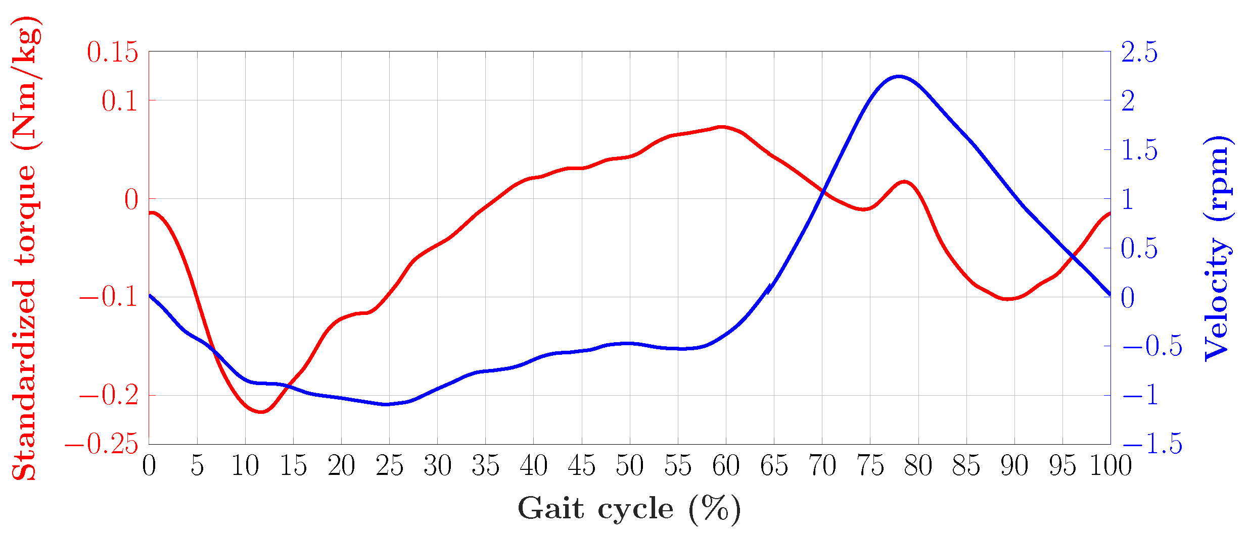
The CPEA is designed for the hip actuation of an exoskeleton or active orthosis in the sagittal plane. The hip has a range of motion from −10 extension to 30 flexion in normal gait, and the drive must, therefore, cover a range of 40. Furthermore, for the safety of the test person, the joint should be equipped with a hard stop within the physiological range of motion [24]. Visual3D was used in experiments with healthy volunteers at slow walking speeds on a treadmill. Figure 1 depicts the torque standardized to the body weight and the speed of the hip at a gait speed of 1.1 km/h, where a 0% gait cycle corresponds to the heel strike. One stride is divided into 40% swing phase and 60% stance phase. These data were recorded from a gait experiment with a healthy volunteer in the motion lab and post-processed with Visual3D. In a stride cycle at that speed, the standardized torque stays below 0.25 Nm/kg, and the maximum speed stays below 2.5 rad/s. Although the maximum torque and the maximum speed do not occur at the same time, the actuator should, therefore, provide at least 120 W of output power, assuming a body weight of 75 kg. These specifications also correspond to the values in Table 1.
The springs for gait support must be exchangeable. The design and spring selection should allow a maximum spring stiffness of at least 50 Nm/rad. Even if for a slower gait velocity, for example 1.1 km/h, lower spring rates are optimal, the larger values are potentially intended to support a faster speed or heavier subjects [11].
In contrast to knee and ankle actuators, a hip actuator does not significantly increase the mass moment of inertia during the swing phase, because it is connected to the torso. In the stance phase, the change in the mass moments of inertia of the individual limbs related to the test person’s body mass is smaller [25,26]. The mass should be kept as low as possible, although the gearbox and motor are typically responsible for almost 2 kg of actuator weight. The hip actuators are more disturbing during the swinging of the arms in comparison to the two other joints. Therefore, the actuator should be as flat as possible, since this enlarges the width of the test person. An axial length of 100 mm is desired for clinical use, to allow the user to pass through doors and walk with crutches [15].
2.2. Structure Designed
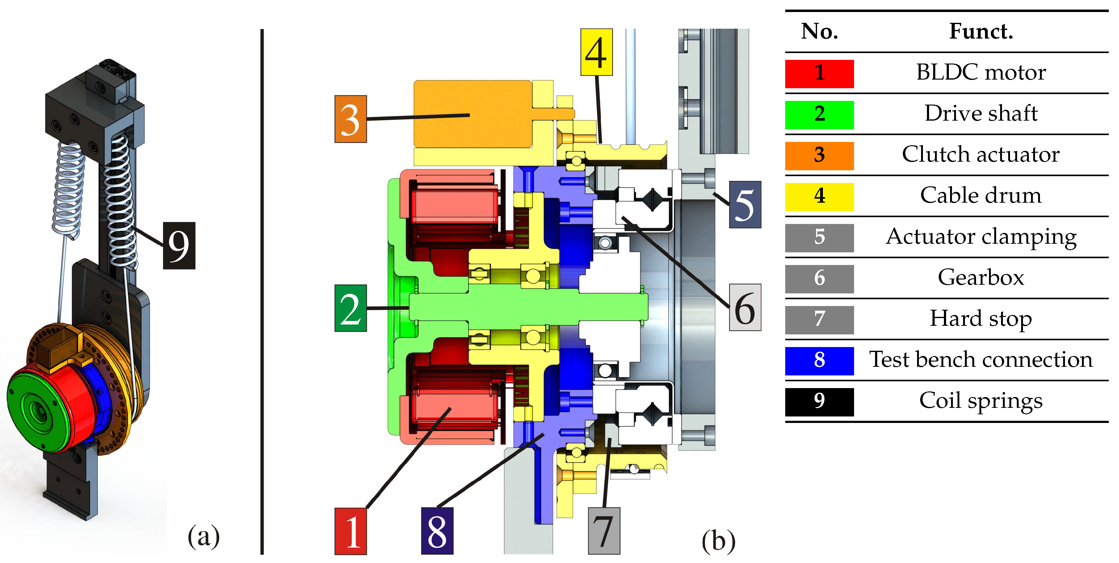
The actuator designed is shown in Figure 2. All important components are numbered consecutively and will be described in the following section. The core task of the actuator is to convert electrical energy into mechanical energy. To fulfill this task, an EC90 Flat Frameless with a 260 W (1) (Maxon Motor AG, Sachseln, Switzerland) motor was chosen. The motor torque is transmitted via the drive shaft (2) to the wave generator (input) of the Harmonic Drive gearbox. The motor can provide a torque of about 1 Nm in rated operation. The gearbox and the engine are connected via the joint connection part (8), and the test bench mount is also mounted here. The load connection (5) for the test bench is connected directly to the output of the gear unit (6). The gearbox is a Harmonic Drive HFUS-2SO with a reduction ratio of 50:1 (6) (Harmonic Drive AG, Limburg an der Lahn, Germany). The load-side crossed roller bearing can subsequently be employed directly as a joint bearing for an exoskeleton (static load rating of 22 kN, maximum axial load of 5150 N, maximum tilting torque of 515 Nm) [27]. An adjustable end position limitation (7) is integrated into the actuator. This allows a swivel range of 120 in the version for the exoskeleton. The swivel range can also be changed by replacing the end position discs. Conventional coil springs (9) with a spring rate ranging from 1.8 N/mm–11.9 N/mm were used to realize the PE. The springs are connected to the cable drum (4) with a wire cable. The springs are extended to half of their maximum length in a neutral position, as this provides the largest swivel range. The lifting armature of the bistable magnet (3) fixes the ratchet disc and the cable drum (4) in a certain position to define the zero position of the springs. A short current pulse is required to fix the springs, and no additional current is needed to maintain the fixation due to the bistable magnet.
2.3. Prototype
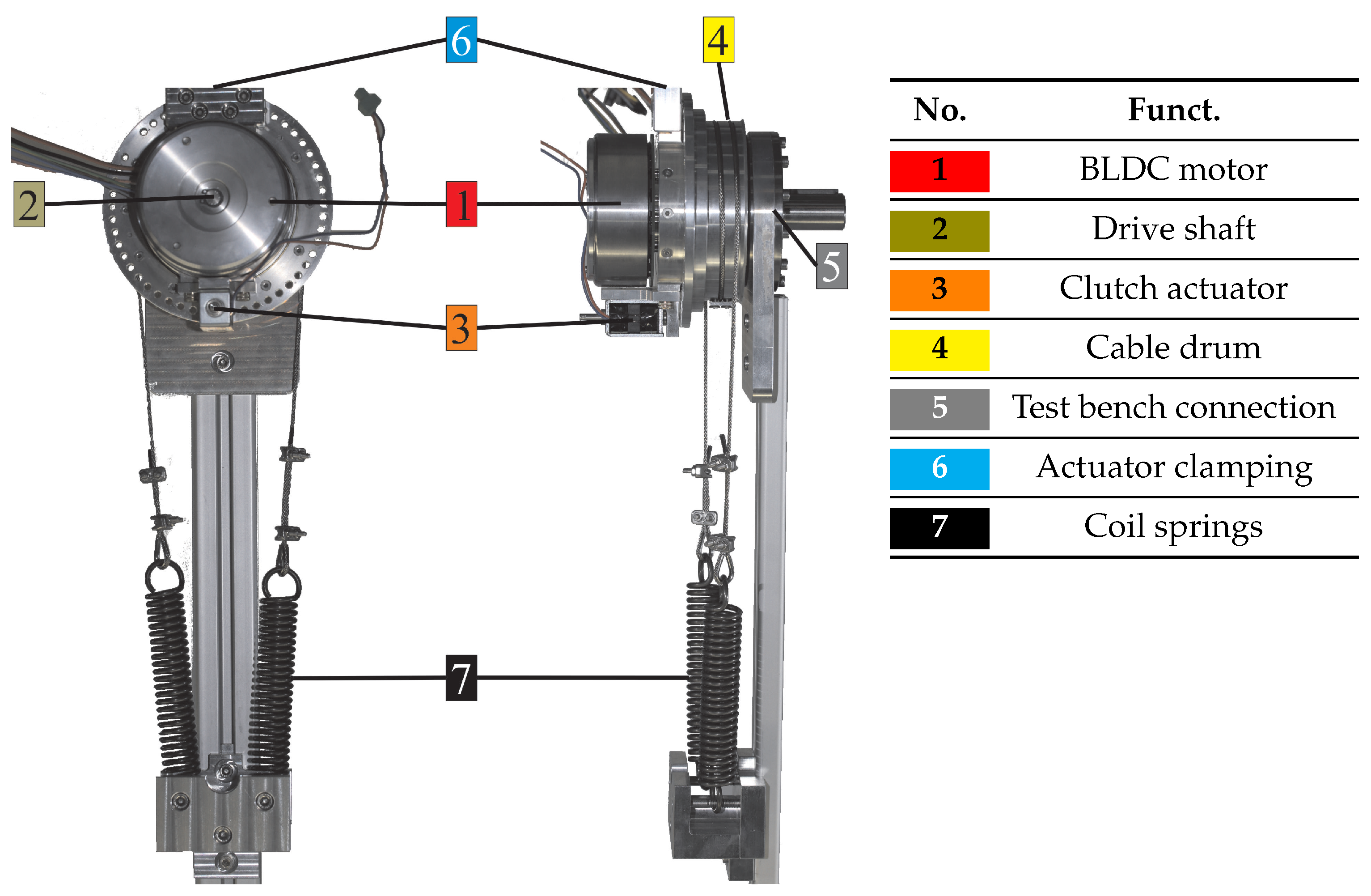
Figure 3 shows the prototype of the CPEA realized in a frontal and side view. In this configuration, a spring stiffness of about 30 Nm/rad was chosen (7). Further spring rates are conceivable, for example, when custom-made springs are used. The springs selected are from the standard product line of Gutekunst + Co. KG (Metzingen, Germany). The test bench connection is optional for connection to the test bench (5). The main components are numbered in the figure. An overview of the technical data of this CPEA is summarized in Table 2. An analytical model of the CPEA will be derived in the following subsection.
3. Modeling and Control
3.1. Modeling
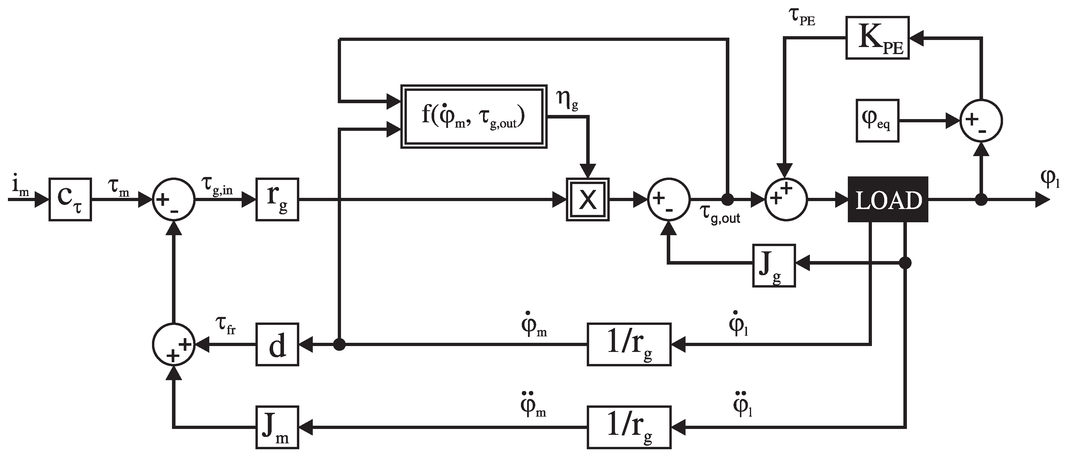
A model with all the essential components was created for the simulation of the actuator and the design of the controllers. The motor was simulated as a current controlled torque source with the motor constant and the motor current . The friction of the motor was modeled as the damping constant d multiplied by the rotational speed . is the moment of inertia of the motor. The torque on the input side of the gear unit is defined by:
The gearbox is modeled by the efficiency curves given in the data sheet. There is a function here that defines the torque efficiency . This function can be approximated according to the data of the Harmonic Drive by:
where the torque factor V is defined by:
The speed-dependent efficiency can be approached by a third order polynomial. Speed efficiency and torque efficiency, Equation (2), functions are summarized as the nonlinear function:
The coefficients were determined using data from the gearbox manufacturer [27]. The input torque was multiplied directly by the reduction ratio and then weighted according to the speed and torque-dependent efficiency. The mass moment of inertia of the gear unit was applied to the output side of the drive. The output torque of the Harmonic Drive gear unit is, thus, defined by:
The PE is represented by its linear spring rate . The equilibrium position of the spring can be set at any position . The spring is tensioned by a deflection of the load position from this equilibrium position. The spring torque is determined by:
The load is actuated by the sum of the gear output torque and the spring torque .
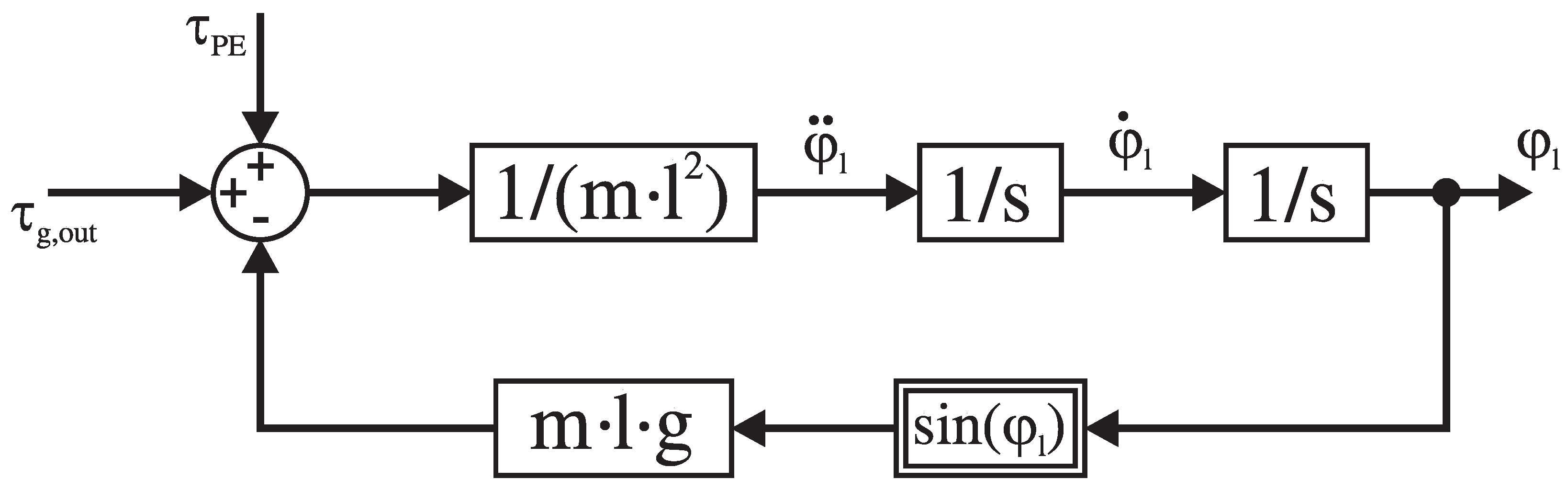
The complete model is graphically summarized as a block diagram in Figure 4, whereby the load as a black box is not specified more precisely, as it is not a fixed component of the actuator.
A pendulum with a dumbbell disc was applied as a load in the experiments. This load can be described by the differential equations:
where m is the mass of the dumbbell disk, l is the distance of the mass from the rotation axis, and g is the gravitational constant. The load position is determined by double integration of Equation (8). The passive load is represented in Figure 5 in the form of a block diagram.
All parameters of the model are summarized in Table 3.
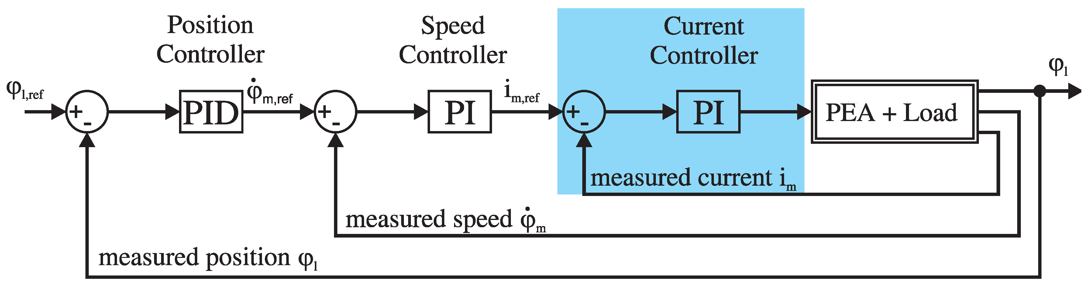
3.2. Cascaded Control
A cascaded control structure, as shown in Figure 6, was applied to control the actuator. The innermost control loop was the current controller of the brushless DC motor. The electrical parameters of the motor are decisive for the design of the controller. This Proportional-Integral (PI) current controller was implemented on the ESCON 50/8 motor control unit of the EC90 Frameless (Maxon Motor AG, Sachseln, Switzerland) and ran at a sampling rate of 53.6 kHz. The speed controller was implemented on a real-time computer (MicroLabBox (MLB), dSPACE GmbH, Paderborn, Germany) system. In contrast to the PI current controller, the connected load also determines the design of the PI speed controller. The position controller was also implemented on the MLB. The system sampling rate on the MLB was set to 10 kHz. The model shown in Figure 4 was applied for speed and position control.
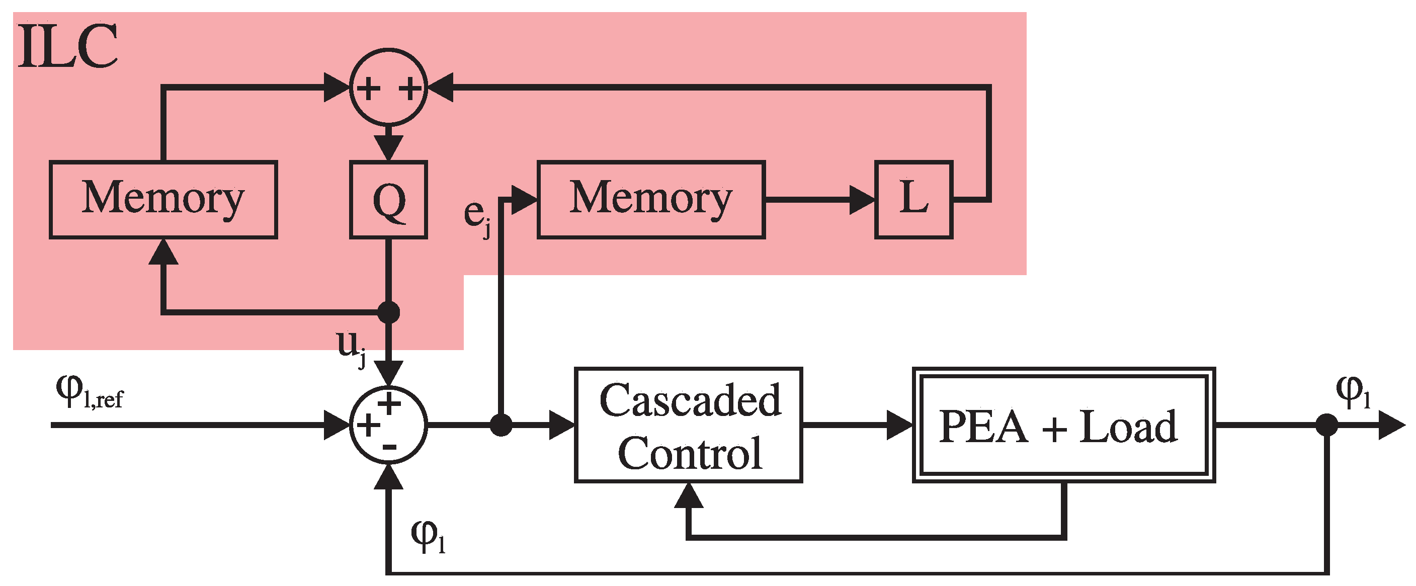
3.3. Iterative Learning Control
A superimposed controller must be implemented in addition to the cascaded control to ensure that the output trajectories match well with the reference values in any experiment. Since the human gait is a very periodic motion task, an ILC is recommended for a better trajectory matching in addition to the cascaded control [28]. The control error was recorded for each cycle and reduced step by step by using the ILC [29]. It is possible to use the serial architecture of the ILC for experimental use with the cascaded controllers implemented in the motor control unit, as shown in Figure 7.
The filters and are called the “learning function” and “Q-filter,” respectively. The ILC is defined by:
where k is the discrete time step in an iteration and is the iteration index. The controller inputs of the current and the last iteration are and , respectively. q is the forward time-shift operator, which is defined as . In our case, the learning function was selected to be:
The Q filter was neglected due to the noiseless digital encoder for the position and high inertia of the real load in the experiment. A forgetting factor can accelerate the convergence of the ILC [30]:
4. Experiments
The step response of the cascaded system was recorded to examine the actuator with cascaded control. Two minutes of gait at 1.1 m/s on the treadmill were recorded in the motion laboratory. The data regarding the optimal spring from the paper by Wang et al. [11] were confirmed by evaluating the gait data in Visual3D (C-Motion Inc., Germantown, MD, USA). As a later input of the system, the positional progression of the hip joint was determined by a Fourier synthesis. This allows a periodic and reproducible reference sequence to be generated. We recall that any periodic function can be represented by a sum of weighted and shifted cosine signals in the form:
where is the magnitude, the frequency and the phase shift. The determined parameters of the Fourier synthesis are listed in Table 4.
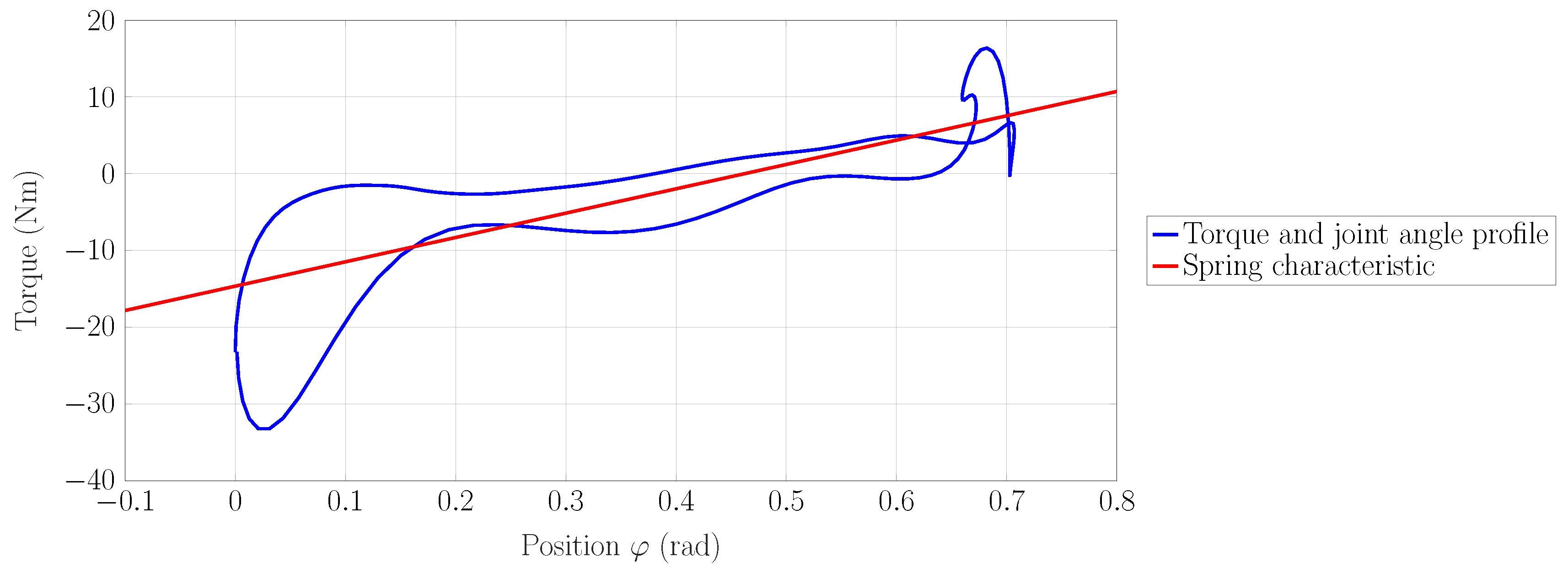
An averaged angle and torque trajectory from Visual3D measurement data was used to determine the spring and the preload angle optimally. The method of calculation was based on the procedure described by Wang et al. [11]. The torque and joint angle profile is shown in Figure 8. The joint torque of the hip in the sagittal plane is plotted over the angular position of the hip joint. To calculate the optimum spring for a complete gait cycle, the stiffness was obtained by linear regression [31]. The spring characteristic curve is defined by:
The solution to Equation (13) was determined using the Curve Fitting Tool in MATLAB. For the gait data selected, the preload angle was about 20, and the spring rate was about KNm/rad. The spring determined is inserted into the profile in Figure 8.
The torque showed a hysteresis behavior in relation to the position . Some reasons for this phenomenon can be identified. For the hip, two arcs of motion can be observed. On the one hand, for the extension in the stance phase, the maximum extension was reached right before the swing phase. On the other hand, this is the swing phase in which the hip flexes [24]. As a result, the flexion and extension of the hip required an individual dynamic model. In stance and swing phase, maximum speed was approximately 1.2 rad/s and 2.3 rad/s respectively for a velocity of 1.1 km/h. Besides, the inertial torque was dependent on the acceleration and the current mass moment of inertia, which changed significantly during a gait cycle. This justifies why the torque characteristic showed the hysteresis behavior. Even if the tendency of the spring effect was nearly evident over the entire torque and joint angle profile, it could be argued why the coefficient of determination of the approximation was only 60.6%.
Experimental Setup
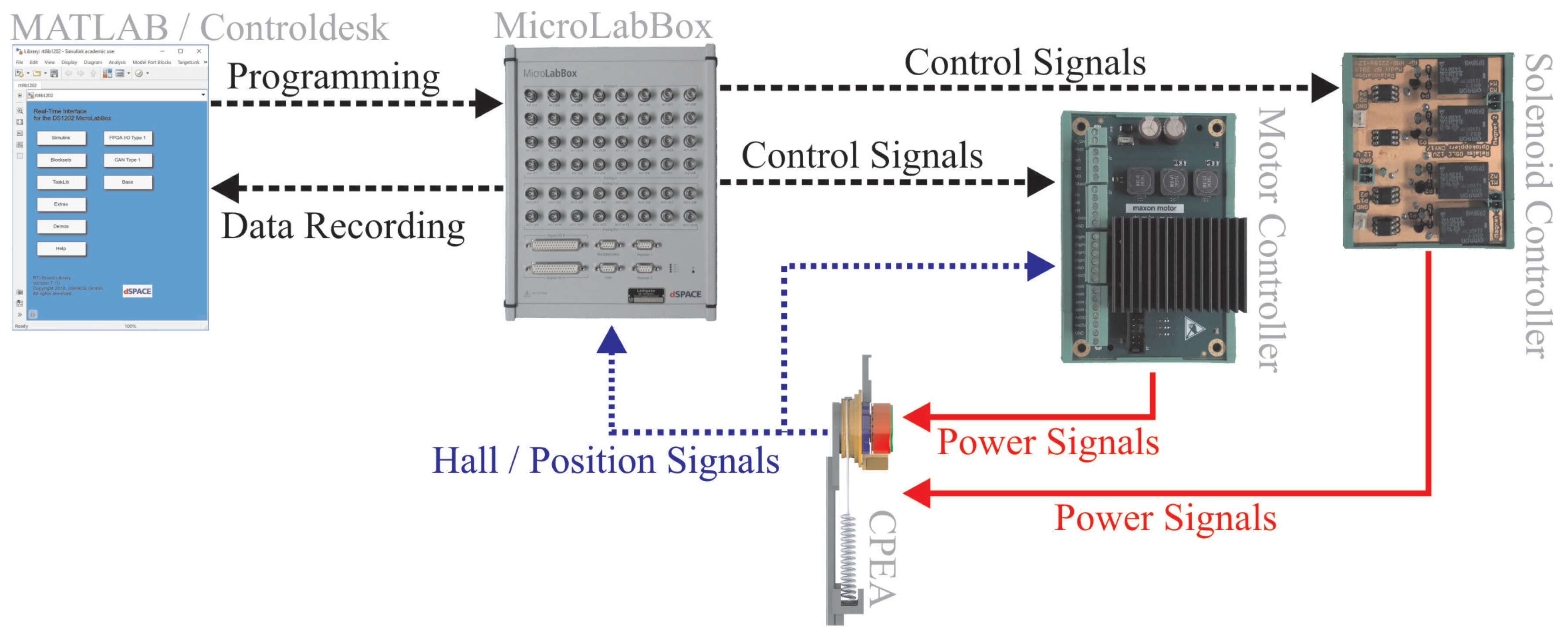
The test bench was set up according to the topology shown in Figure 9 to perform the experiments. The spring was deactivated or activated by the switching agent in the experiments; a self-made relay board was built for its control. Current and speed controllers were integrated into the motor controller. The MLB was selected to implement the superimposed position control and the ILC. The values measured were recorded via the connection between the computer and the MLB.
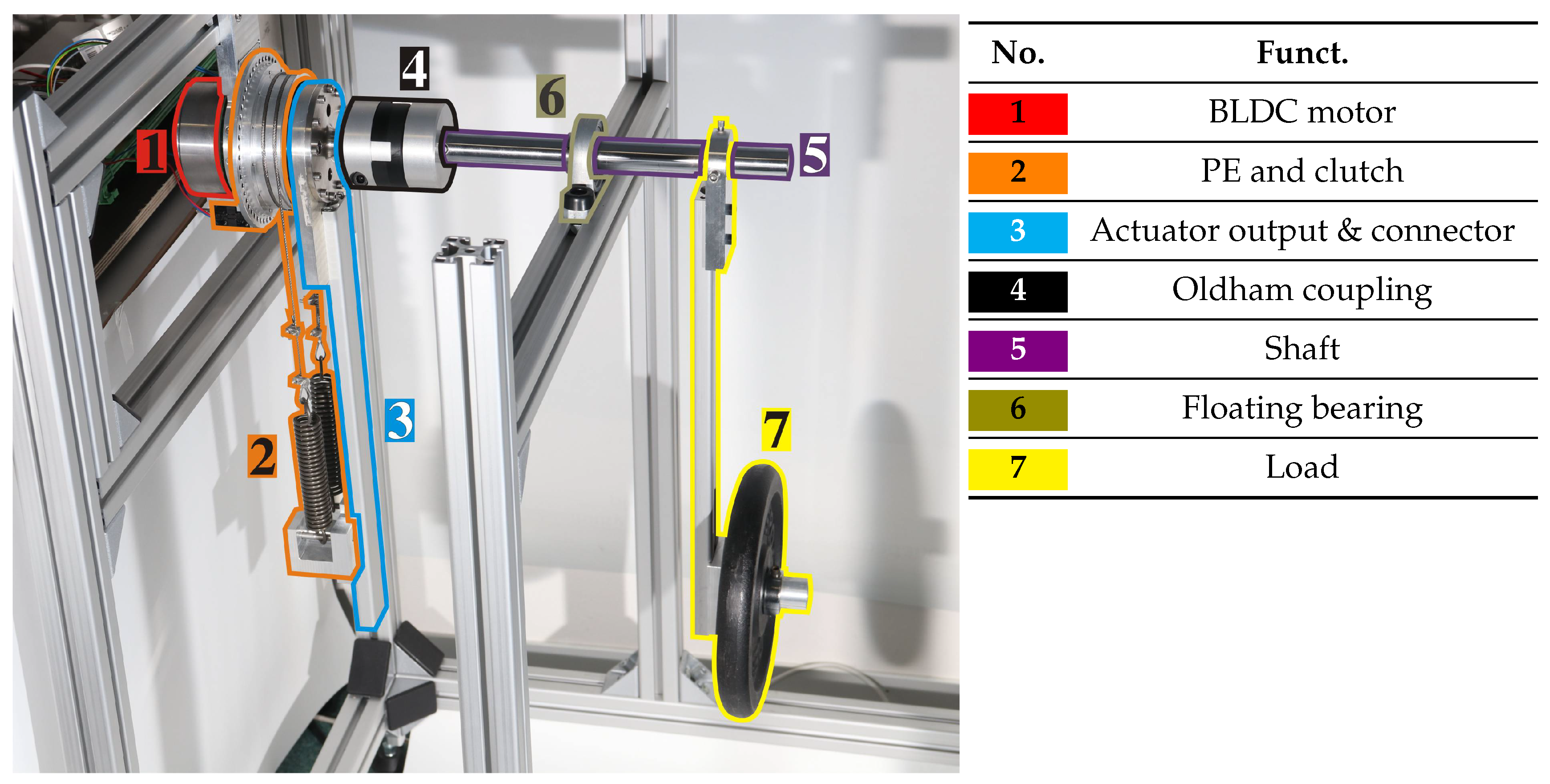
The mechanical structure of the test bench during the experiments is shown in Figure 10. The actuator CPEA (motor (1) and the PE with clutch (2)) were attached to an aluminum profile frame. Actuator output (3) and shaft (5) were connected by an Oldham coupling (4). The CPEA cross-roller bearing was supplemented by a floating bearing (6) (bearing block PBT25, Misumi, Koto, Tokyo, Japan) close to the load. During the tests, the actuator was equipped with a load pendulum (7) with a lever arm of 0.4 m and a mass of 5 kg, and the mass moment of inertia was Jmkg, an approximation of the leg in the swing phase, when the thigh and the lower leg were considered as point masses [25].
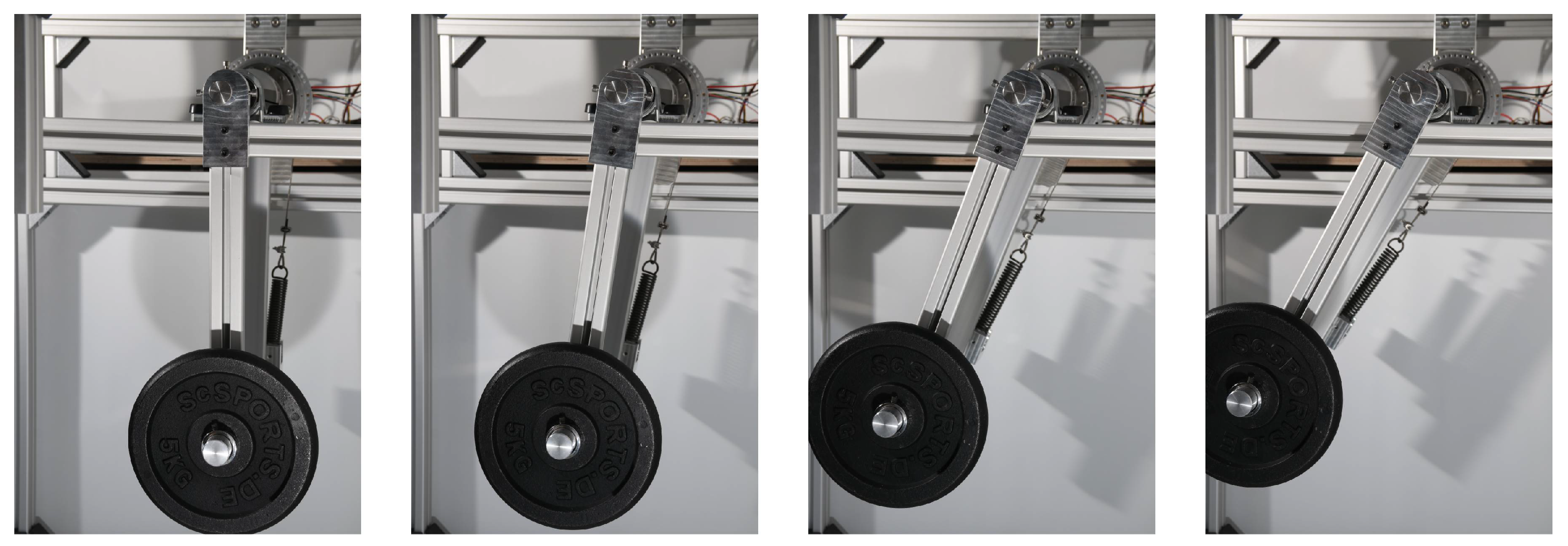
Figure 10 shows the test bench with mounted CPEA and load. Figure 11 shows the load at different positions (0, 10, 20, and 30) during the experiment. One of the two coil springs was visible at this angle, and the greatest elongation in this experiment was only about half of the maximum allowed elongation of the spring. By reducing the diameter of the cable drum of the actuator, the range of rotation would increase, so that the spring constants would decrease.
5. Results and Discussion
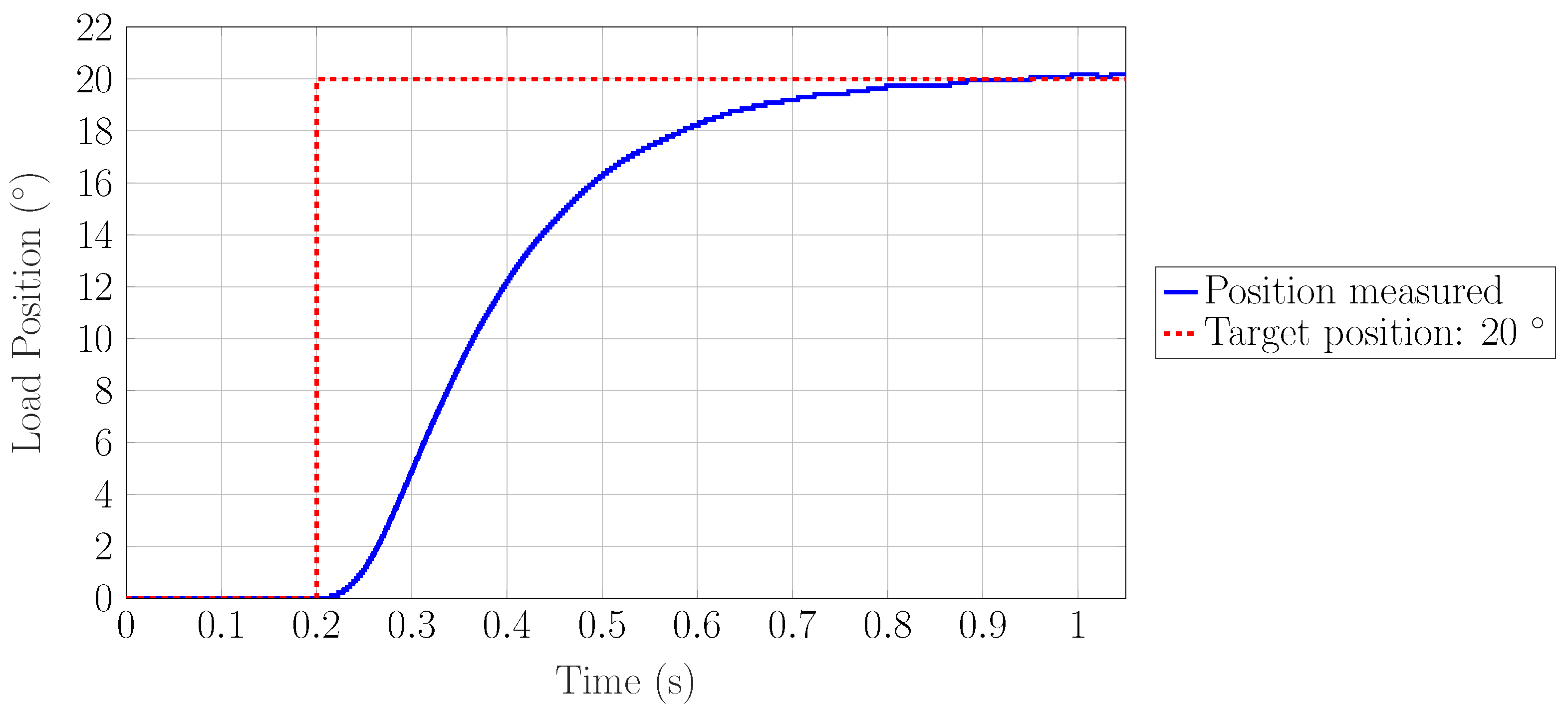
The results of the step response and the controlled operation with a hip trajectory for 1.1 m/s follow. The ILC was only applied to the gait trajectories. For the step response, the cascaded control was applied as it was not a cyclic task. First, the step response is shown in Figure 12.
The set point was reached after about 0.6 s with an input step of 20 to the cascaded controlled actuator without parallel springs. The motor allowed a 13-fold current overload at start-up, and the collusion torque of the gearbox was 98 Nm. For the safety of the gearbox, the over-current in the motor controller was limited accordingly to 8 A (twice the nominal value). The maximum torque of the motor limited the minimum response time. In the next paragraph, the experiments with reference trajectories of the hip are presented.
The angular course of the ILC-controlled actuator with PE and without elasticity was shown in this experiment, while they can hardly be separated in Figure 13. The ILC did not work in the first cycle; therefore, the control deviation was larger. Since the load is a pendulum, and thus a non-linear load (see Equation (8)), the controller was optimized for a particular operating point. Without ILC, this can lead to larger control deviations if the operating point is changed. By readjusting the controllers, a better working cascaded controller could be found especially for this task. Adaptive adaptation of the controllers would improve the disturbance transfer function in a test environment with stochastic disturbances. The ILC achieved a highly similar system response for both configurations for this input function. As can be seen from the second cycle onwards in Figure 13, the error was reduced significantly. The root mean square error (RMSE) was calculated to evaluate the improvement of the control error:
where n = 13,247 is the number of measurement samples during one gait cycle. The iterative improvement of the RMSE during experiments is listed in Table 5.
It should be noted that the angle discretization during the experiment was 0.11°. By comparing the RMS errors of both configurations, it can be shown that the angle profile can be compared with and without PE, since the motion task was executed with identical accuracy. Thus, different characteristic values for the actuator with and without PE can be compared directly.
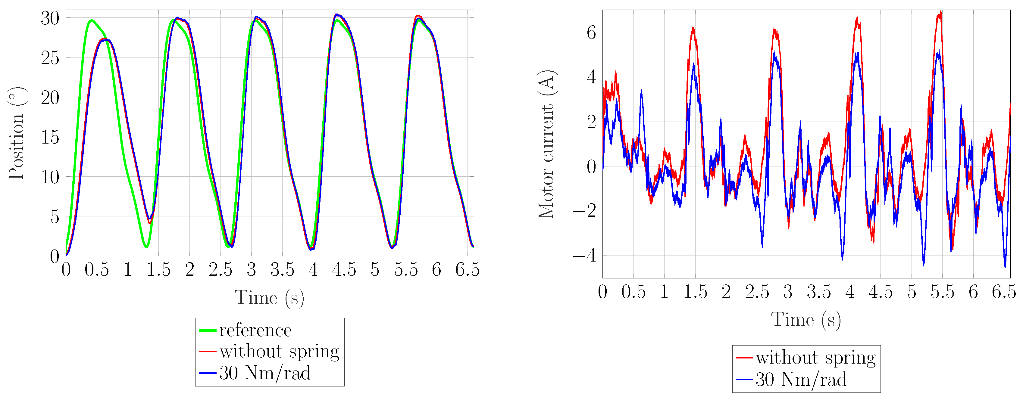
The motor current and the motor torque are important selection parameters for an electric motor. Therefore the current is the first metric of our analysis. The peak current at the reference trajectory for the hip has been reduced from 7.0 A to 5.2 A in the experiment, as shown in Figure 13.
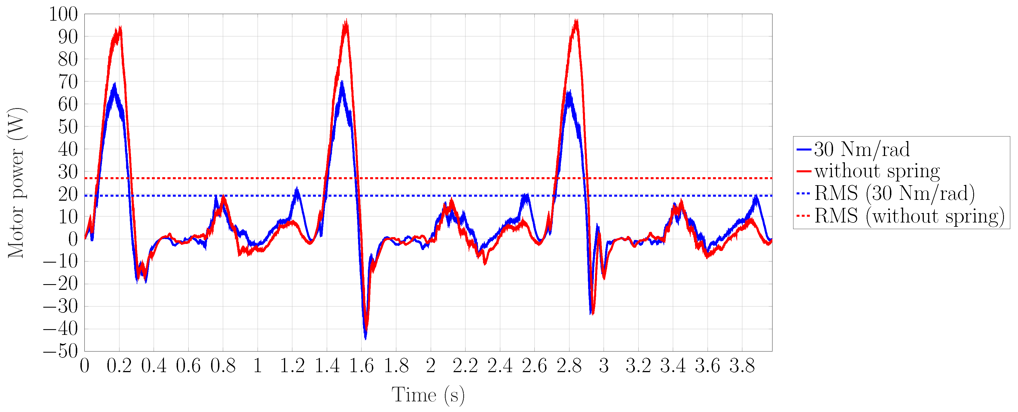
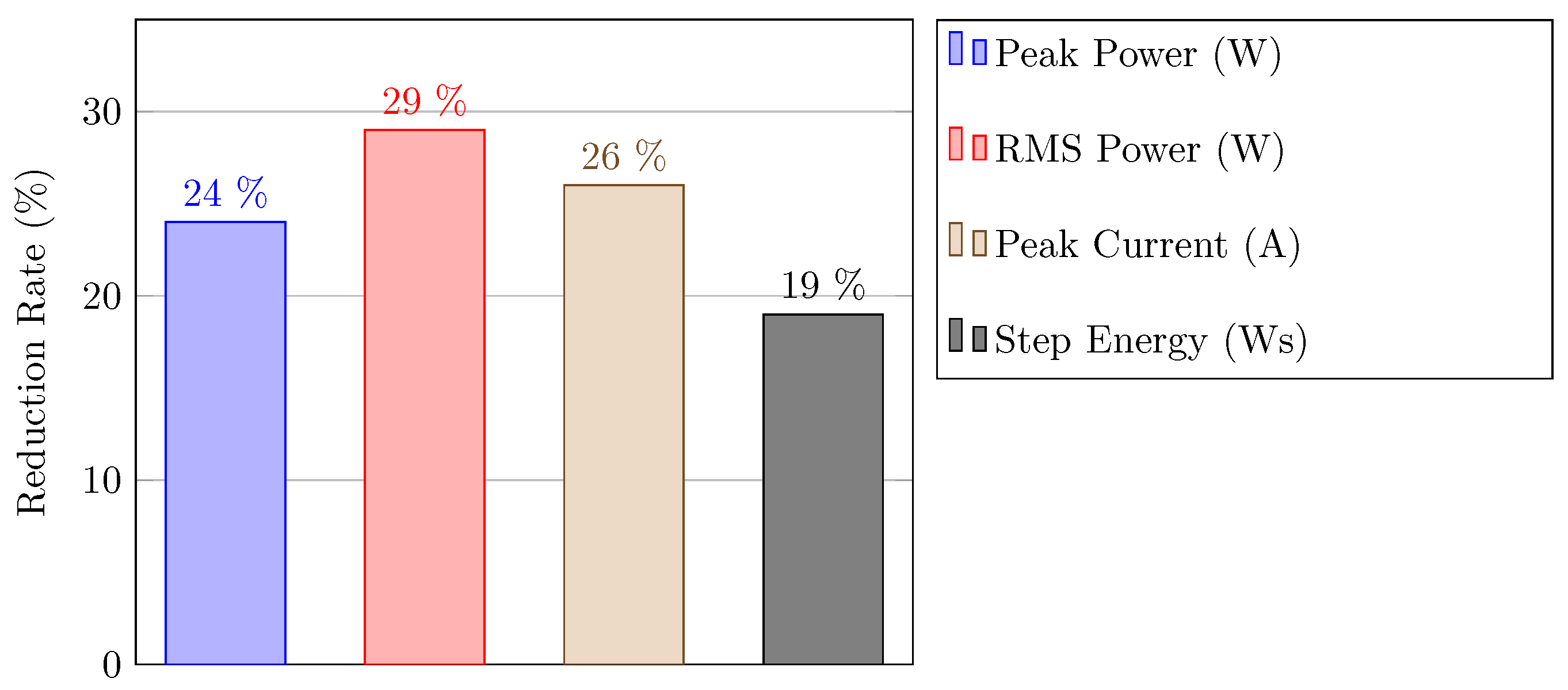
The motor power during the tests is shown in Figure 14. When dimensioning the motor, the maximum power consumption was another selection criterion. The maximum power consumption was reduced from 94.7 to 71.1 W (24%) for the hip reference trajectory. The average RMS power and the energy consumption per step were important for the dimensioning of the entire system with battery or power supply. The RMS power was reduced from 26.9 to 19.1 W (29%) by using PE. The quantity of energy per step was reduced from 18.4 to 14.9 Ws (19%). The PE in the motion tests with the hip trajectory on the test bench reduced all characteristic specification values significantly. To summarize, the relative improvements of the characteristic specification values are shown in Figure 15.
A reduction of the characteristic values was important in dimensioning the actuator, so that a smaller motor could be selected through this reduction and the gearbox could be designed smaller through the resulting reduced torques. In the long run, a portable power supply (battery) can be made smaller, potentially saving much weight in the overall design. A disadvantage that should be mentioned is that the mechanical spring with its mechanism was an extra weight compared to a rigid actuator. In our design, the additional weight due to the PE was between 380 and 690 g, depending on the spring rate desired. In order to give an impression of the component weight, the engine selected is available in a smaller configuration with about half the torque, which weighs 320 g less. This variation would at the same time reduce the axial length by 12 mm.
6. Conclusions
Our study confirmed that the CPEA reduced all characteristic specification values significantly (see Figure 15). A verification with direct human–machine interaction is still to be performed. Due to the fact that the elasticity can be deactivated, the actuator can also behave like a rigid actuator in non-periodic tasks, which excludes the disadvantages of a PEA here. The development of CPEA actuators seems promising due to the potential weight and consumption reduction for use in mobile rehabilitation robots. Development and research efforts are still needed to integrate CPEA drives into an exoskeleton and confirm the advantages of the actuator topology in studies with volunteers.
Author Contributions
Conceptualization, B.P.; data curation, B.P. and M.E.F.; formal analysis, B.P.; funding acquisition, L.J. and S.L.; investigation, B.P.; methodology, B.P.; project administration, B.P. and C.N.; resources, B.P.; software, B.P. and M.E.F.; supervision, B.P., L.J. and S.L.; validation, B.P. and M.E.F.; visualization, B.P.; writing, original draft, B.P.; writing, review and editing, B.P., Y.L. and C.N.
Funding
The research was funded by the joint Deutsche Forschungsgemeinschaft (DFG, German Research Foundation) and the National Natural Science Foundation of China (NSFC) project “Hybrid parallel compliant actuation for lower limb rehabilitation-HYPACAL” (LE 817/34-1) (NSFC 51761135121).
Conflicts of Interest
The authors declare no conflicts of interest. The funders had no role in the design of the study, in the collection, analyses, or interpretation of data, in the writing of the manuscript, nor in the decision to publish the results.
Abbreviations
The following abbreviations are used in this manuscript:
| BLDC | Brushless Direct Current |
| CPEA | Clutched Parallel Elastic Actuator |
| ILC | Iterative Learning Control |
| MACCEPA | Mechanically-Adjustable Compliance and Controllable Equilibrium Position Actuator |
| MLB | MicroLabBox |
| PE | Parallel Elasticity |
| PEA | Parallel Elastic Actuator |
| PI Controller | Proportional-Integral Controller |
| PID Controller | Proportional-Integral-Derivative Controller |
| RA | Rigid Actuator |
| RMS | Root Mean Square |
| SEA | Series Elastic Actuator |
| cRSEA | Clutched Rigid Series Elastic Actuator |
References
- Ham, R.V.; Sugar, T.G.; Vanderborght, B.; Hollander, K.W.; Lefeber, D. Compliant actuator designs. IEEE Robot. Autom. Mag. 2009, 16, 81–94. [Google Scholar] [CrossRef]
- Maciejasz, P.; Eschweiler, J.; Gerlach-Hahn, K.; Jansen-Troy, A.; Leonhardt, S. A survey on robotic devices for upper limb rehabilitation. J. Neuroeng. Rehabil. 2014, 11, 3. [Google Scholar] [CrossRef] [PubMed]
- Jafari, A.; Tsagarakis, N.G.; Vanderborght, B.; Caldwell, D.G. A novel actuator with adjustable stiffness (AwAS). In Proceedings of the IEEE/RSJ International Conference on Intelligent Robots and Systems, Taipei, Taiwan, 18–22 October 2010; pp. 4201–4206. [Google Scholar]
- Plooij, M.; Wolfslag, W.; Wisse, M. Clutched elastic actuators. IEEE-ASME Trans. Mech. 2017, 22, 739–750. [Google Scholar] [CrossRef]
- Plooij, M.; van Nunspeet, M.; Wisse, M.; Vallery, H. Design and evaluation of the Bi-directional Clutched Parallel Elastic Actuator (BIC-PEA). In Proceedings of the IEEE International Conference on Robotics and Automation (ICRA), Washington State Convention Centre, Seattle, WA, USA, 25–30 May 2015; pp. 1002–1009. [Google Scholar]
- Stuhlenmiller, F.; Schuy, J.; Beckerle, P.; Rinderknecht, S. A user-specific human-machine interaction strategy for a prosthetic shank adapter. Curr. Dir. Biomed. Eng. 2017, 3, 493–496. [Google Scholar] [CrossRef] [Green Version]
- Grimmer, M.; Eslamy, M.; Gliech, S.; Seyfarth, A. A comparison of parallel-and series elastic elements in an actuator for mimicking human ankle joint in walking and running. In Proceedings of the 2012 IEEE International Conference on Robotics and Automation, Saint Paul, MN, USA, 14–18 May 2012; pp. 2463–2470. [Google Scholar]
- Roozing, W.; Li Medrano-Cerda, Z.; Gustavo, A.; Caldwell, D.; Tsagarakis, N. Development and control of a compliant asymmetric antagonistic actuator for energy efficient mobility. IEEE-ASME Trans. Mech. 2015, 21, 1080–1091. [Google Scholar] [CrossRef]
- Liu, X.; Rossi, A.; Poulakakis, I. A Switchable Parallel Elastic Actuator and its Application to Leg Design for Running Robots. IEEE-ASME Trans. Mech. 2018, 23, 2681–2692. [Google Scholar] [CrossRef]
- Masood, J.; Ortiz, J.; Fernández, J.; Mateos, L.; Caldwell, D. Mechanical design and analysis of light weight hip joint parallel elastic actuator for industrial exoskeleton. In Proceedings of the 2016 6th IEEE International Conference on Biomedical Robotics and Biomechatronics (BioRob), Singapore, 26–29 June 2016; pp. 631–636. [Google Scholar]
- Wang, S.; Van Dijk, W.; Van der Kooij, H. Spring uses in exoskeleton actuation design. In Proceedings of the 2011 IEEE International Conference on Rehabilitation Robotics (ICORR), Zurich, Switzerland, 29 June–1 July 2011; pp. 1–6. [Google Scholar]
- Mettin, U.; La Hera, P.; Freidovich, L.; Shiriaev, A. Parallel elastic actuators as a control tool for preplanned trajectories of underactuated mechanical systems. Int. J. Robot. Res. 2010, 29, 1186–1198. [Google Scholar] [CrossRef]
- Li, Y.; Li, Z.; Penzlin, B.; Tang, Z.; Liu, Y.; Guan, X.; Ji, L.; Leonhardt, S. Design of the Clutched Variable Parallel Elastic Actuator (CVPEA) for lower Limb Exoskeletons. In Proceedings of the 41st International Conference of the IEEE Engineering in Medicine and Biology Society (EMBC), Berlin, Germany, 23–27 July 2019. accepted. [Google Scholar]
- Häufle, D.; Taylor, M.D.; Schmitt, S.; Geyer, H. A clutched parallel elastic actuator concept: Towards energy efficient powered legs in prosthetics and robotics. In Proceedings of the 4th IEEE RAS & EMBS International Conference on Biomedical Robotics and Biomechatronics (BioRob), Rome, Italy, 24–27 June 2012. [Google Scholar]
- Cestari, M.; Sanz-Merodio, D.; Arevalo, J.; Garcia, E. An adjustable compliant joint for lower-limb exoskeletons. IEEE-ASME Trans. Mech. 2015, 20, 889–898. [Google Scholar] [CrossRef]
- Lewis, C.; Sahrmann, S. Effect of posture on hip angles and moments during gait. Man. Ther. 2015, 20, 176–182. [Google Scholar] [CrossRef] [PubMed]
- Toxiri, S.; Calanca, A.; Ortiz, J.; Fiorini, P.; Caldwell, D.G. A parallel-elastic actuator for a torque-controlled back-support exoskeleton. IEEE Robot. Autom. Lett. 2017, 3, 492–499. [Google Scholar] [CrossRef]
- Brackx, B.; Geeroms, J.; Vantilt, J.; Grosu, V.; Junius, K.; Cuypers, H.; Vanderborght, B.; Lefeber, D. Design of a modular add-on compliant actuator to convert an orthosis into an assistive exoskeleton. In Proceedings of the 5th IEEE RAS/EMBS International Conference on Biomedical Robotics and Biomechatronics, Sao Paulo, Brazil, 12–15 August 2014; pp. 485–490. [Google Scholar]
- Zhang, T.; Tran, M.; Huang, H. Design and experimental verification of hip exoskeleton with balance capacities for walking assistance. IEEE-ASME Trans. Mech. 2018, 23, 274–285. [Google Scholar] [CrossRef]
- Woo, H.; Na, B.; Kong, K. Design of a compact rotary series elastic actuator for improved actuation transparency and mechanical safety. In Proceedings of the 2017 IEEE International Conference on Robotics and Automation (ICRA), Singapore, 29 May–3 June 2017; pp. 1872–1877. [Google Scholar]
- Önen, Ü.; Botsalı, F.; Kalyoncu, M.; Tınkır, M.; Yılmaz, N.; Şahin, Y. Design and actuator selection of a lower extremity exoskeleton. IEEE-ASME Trans. Mech. 2013, 19, 623–632. [Google Scholar] [CrossRef]
- Neuhaus, P.D.; Noorden, J.H.; Craig, T.J.; Torres, T.; Kirschbaum, J.; Pratt, J.E. Design and evaluation of Mina: A robotic orthosis for paraplegics. In Proceedings of the 2011 IEEE International Conference on Rehabilitation Robotics, Zurich, Switzerland, 29 June–1 July 2011; pp. 1–8. [Google Scholar]
- Lee, S.; Sankai, Y. Power assist control for leg with hal-3 based on virtual torque and impedance adjustment. In Proceedings of the IEEE International Conference on Systems, Man and Cybernetics, Yasmine Hammamet, Tunisia, 6–9 October 2002. [Google Scholar]
- Perry, J.; Burnfield, J. Gait Analysis-Normal and Pathological Function; Slack Inc.: Thorofare, NJ, USA, 2010; pp. 176–182. [Google Scholar]
- De Leva, P. Adjustments to Zatsiorsky-Seluyanov’s segment inertia parameters. J. Biomech. 1996, 29, 1223–1230. [Google Scholar] [CrossRef]
- Vallery, H.; Veneman, J.; Van Asseldonk, E.; Ekkelenkamp, R.; Buss, M.; Van Der Kooij, H. Compliant actuation of rehabilitation robots. IEEE Robot. Autom. Mag. 2008, 15, 60–69. [Google Scholar] [CrossRef] [Green Version]
- Harmonic Drive AG. Projektierungsanleitung Units HFUS-2UH/2SO/2SH; Harmonic Drive AG: Limburg an der Lahn, Germany, 2014. [Google Scholar]
- Nahrstaedt, H.; Schauer, T.; Hesse, S.; Raisch, J. Iterative Learning Control of a Gait Neuroprosthesis. Automatisierungstechnik 2008, 56, 494–501. [Google Scholar] [CrossRef]
- Bristow, D.; Tharayil, M.; Alleyne, A. A survey of iterative learning control. IEEE Control. Syst. Mag. 2006, 26, 96–114. [Google Scholar]
- Yang, H.; Li, S. PD-Type ILC Algorithm Research with Forgetting Factor for a Class of Linear Systems with Multiple Time Delays. Appl. Mech. Mater. 2012, 220, 1125–1130. [Google Scholar] [CrossRef]
- Rouse, E.J.; Gregg, R.D.; Hargrove, L.J.; Sensinger, J.W. The difference between stiffness and quasi-stiffness in the context of biomechanical modeling. IEEE Trans. Biomed. Eng. 2012, 60, 562–568. [Google Scholar] [CrossRef] [PubMed]
Figure 1.
Measurement of a healthy volunteer: standardized torque and speed of the hip during the gait at 1.1 km/h.
Figure 1.
Measurement of a healthy volunteer: standardized torque and speed of the hip during the gait at 1.1 km/h.

Figure 2.
Images of a CPEA generated by computer-animated design: (a) Actuator in configuration for the test bench integration. (b) Sectional view of the actuator (without Parallel Elasticity (PE)).
Figure 2.
Images of a CPEA generated by computer-animated design: (a) Actuator in configuration for the test bench integration. (b) Sectional view of the actuator (without Parallel Elasticity (PE)).

Figure 3.
Photo of the completed prototype with the indication of the functionalities.

Figure 4.
Block diagram of the PEA with an undefined load.

Figure 5.
Block diagram of the passive load.

Figure 6.
Cascaded control scheme. The current controller is implemented in the motor controller, which is marked with a blue area.
Figure 6.
Cascaded control scheme. The current controller is implemented in the motor controller, which is marked with a blue area.

Figure 7.
Position control consisting of an iterative learning controller (which is marked with a red area) in series with the cascaded feedback controller.
Figure 7.
Position control consisting of an iterative learning controller (which is marked with a red area) in series with the cascaded feedback controller.

Figure 8.
Measurement of a healthy volunteer: averaged torque and joint angle profile of the hip during a measured gait at 1.1 m/s and the spring characteristic determined.
Figure 8.
Measurement of a healthy volunteer: averaged torque and joint angle profile of the hip during a measured gait at 1.1 m/s and the spring characteristic determined.

Figure 9.
Schematic representation of the experimental setup.

Figure 10.
Configuration of the test bench with mounted CPEA and load.

Figure 11.
Photo sequence of the experiments. Range of motion: 0–30.

Figure 12.
Step response of the CPEA with a pendulum load.

Figure 13.
Comparison of PEA with a 30-Nm/rad spring (equilibrium position 20) and rigid actuator. Left: the position trajectory for a reference of the hip; right: the motor current associated with the trajectory.
Figure 13.
Comparison of PEA with a 30-Nm/rad spring (equilibrium position 20) and rigid actuator. Left: the position trajectory for a reference of the hip; right: the motor current associated with the trajectory.

Figure 14.
Motor power of the rigid actuator and PEA with 30Nm/rad spring (Eq. Position 20).

Figure 15.
Reduction of the characteristic values due to the parallel elasticity, in a hip-like trajectory.
Figure 15.
Reduction of the characteristic values due to the parallel elasticity, in a hip-like trajectory.


Table 1.
Overview: actuators for supporting the hip motion (* marks 30% torque support).
| Topology | Power | Rated Torque | Velocity | Spring Rate | Purpose | Ref. |
|---|---|---|---|---|---|---|
| PEA | 100 W | 28.9 Nm | 37.4 rpm | 8 Nm/rad | Industrial | [17] |
| MACCEPA | 50 W | 11.2 Nm * | 28 rpm | 28.1 to 81.4 Nm/rad | Sit-to-stand | [18] |
| SEA | 90 W | 40 Nm | 25 rpm | 123 Nm/rad | Walking | [19] |
| cRSEA | 200 W | 18.2 Nm | 84.7 rpm | Energy buffer/torque sensor | Walking | [20] |
| RA | 100 W | 34 Nm | 25 rpm | Not applicable | Walking | [21] |
| RA | 355 W | 40.5 Nm | 75 rpm | 24 kNm/rad | Walking (0.2 m/s) | [22] |
| RA | 150 W | 68.6 Nm | 36.3 rpm | Not applicable | Walking | [23] |
Table 2.
Technical data of the Clutched Parallel Elastic Actuator (CPEA).
| Specifications | Value |
|---|---|
| Nominal torque | 49.4 Nm (active only) |
| Nominal speed | 3.7 rad/s |
| No load speed | 4.4 rad/s |
| Rated motor power | 260 W (Maxon EC 90) |
| Mass | 3.1 kg (including 30 Nm/rad springs) |
| Axial length | 105 mm (including leg adapter) |
| Spring rate | 10–67 Nm/rad (Mass: 50–360 g) |
| Spring type | Steel tension springs (EN 10270-1) |
| Clutch actuator | Bistable solenoid (30 W) |
Table 3.
All parameters of the model including their name, symbol, and value.
| Name | Symbol | Value |
|---|---|---|
| Rotor inertia | 5.300 · 10 kg·m | |
| Torque constant | 0.136 Nm/A | |
| Speed constant | 7.35 rad/Vs | |
| Motor resistance | 0.29 | |
| Motor inductance | 0.369 H | |
| Damping constant (motor) | d | 1.5 Nm/rad |
| Spring rate (PE) | 30 Nm/rad | |
| Equilibrium position | 0.35 rad | |
| Nominal torque (gearbox) | 25 Nm | |
| Gearbox inertia | 1.93 kg· m | |
| Reduction ratio | 50:1 | |
| Coefficients (torque efficiency) | 1.019 | |
| −0.00765 | ||
| −0.849 | ||
| 1.758 | ||
| Coefficients (speed efficiency) | 0.8776 | |
| −0.0008136 s/rad | ||
| s/rad | ||
| s/rad | ||
| Load inertia | 0.8 kg· m | |
| Gravitational constant | g | 9.81 m/s |
| Mass of the load | m | 5 kg |
Table 4.
The first seven frequencies, amplitudes, and phase shifts of the cosine envelopes for the periodic approximation of hip movement.
Table 4.
The first seven frequencies, amplitudes, and phase shifts of the cosine envelopes for the periodic approximation of hip movement.
| Number i | 0 | 1 | 2 | 3 | 4 | 5 | 6 |
|---|---|---|---|---|---|---|---|
| Frequency | shift | Hz | Hz | Hz | Hz | Hz | Hz |
| Magnitude | |||||||
| Phase shift |
Table 5.
Iterative improvement of the RMS error of the load position achieved by the ILC.
| Iteration | 1 | 2 | 3 | 4 | 5 | 6 | 7 |
|---|---|---|---|---|---|---|---|
| RMSE |
© 2019 by the authors. Licensee MDPI, Basel, Switzerland. This article is an open access article distributed under the terms and conditions of the Creative Commons Attribution (CC BY) license (http://creativecommons.org/licenses/by/4.0/).
Share and Cite
MDPI and ACS Style
Penzlin, B.; Enes Fincan, M.; Li, Y.; Ji, L.; Leonhardt, S.; Ngo, C. Design and Analysis of a Clutched Parallel Elastic Actuator. Actuators 2019, 8, 67. https://doi.org/10.3390/act8030067
AMA Style
Penzlin B, Enes Fincan M, Li Y, Ji L, Leonhardt S, Ngo C. Design and Analysis of a Clutched Parallel Elastic Actuator. Actuators. 2019; 8(3):67. https://doi.org/10.3390/act8030067
Chicago/Turabian StylePenzlin, Bernhard, Mustafa Enes Fincan, Yinbo Li, Linhong Ji, Steffen Leonhardt, and Chuong Ngo. 2019. "Design and Analysis of a Clutched Parallel Elastic Actuator" Actuators 8, no. 3: 67. https://doi.org/10.3390/act8030067
Note that from the first issue of 2016, this journal uses article numbers instead of page numbers. See further details here.