Review of Electrothermal Actuators and Applications

Institute of Sensors, Signals and Systems, School of Engineering and Physical Sciences, Heriot-Watt University, Edinburgh EH14 4AS, UK
*
Author to whom correspondence should be addressed.
Actuators 2019, 8(4), 69; https://doi.org/10.3390/act8040069
Submission received: 31 July 2019
/
Revised: 12 September 2019
/
Accepted: 19 September 2019
/
Published: 21 September 2019
Abstract
:This paper presents a review of electrothermal micro-actuators and applications. Electrothermal micro-actuators have been a significant research interest over the last two decades, and many different designs and applications have been investigated. The electrothermal actuation method offers several advantages when compared with the other types of actuation approaches based on electrostatic and piezoelectric principles. The electrothermal method offers flexibility in the choice of materials, low-cost fabrication, and large displacement capabilities. The three main configurations of electrothermal actuators are discussed: hot-and-cold-arm, chevron, and bimorph types as well as a few other unconventional actuation approaches. Within each type, trends are outlined from the basic concept and design modifications to applications which have been investigated in order to enhance the performance or to overcome the limitations of the previous designs. It provides a grasp of the actuation methodology, design, and fabrication, and the related performance and applications in cell manipulation, micro assembly, and mechanical testing of nanomaterials, Radio Frequency (RF) switches, and optical Micro-Electro-Mechanical Systems (MEMS).
1. Introduction
The trend of rapid miniaturization in the last two decades or so has led to remarkable progress in the field of micro-electro-mechanical systems (MEMS). The MEMS devices, in comparison with the complex and bulky alternatives, can offer superior performance with low power consumption, small size, low cost, fast operation, flexibility of design, and easy integration with on-chip electronics [1,2]. One of the key aspects of MEMS design is the choice of actuation methods. Currently, five major types of actuators are widely used in MEMS [1,3]: electrothermal, electrostatic, piezoelectric, electromagnetic, and shape memory alloy (SMA) based actuators. The scope of the present review is electrothermal actuators and their applications. Electrothermal actuation is based on a balance between the thermal energy generated by an electrical current and the heat dissipation through the environment or the substrate. The three conventional types of electrothermal actuators discussed in this review are hot-and-cold-arm, chevron, and bimorph designs. For operation, the hot-and-cold-arm actuator utilizes the asymmetric thermal expansion of its parts. The chevron actuators use the total thermal expansion which is constrained in one direction. On the other hand, the bimorph actuator relies on the difference in coefficients of thermal expansion (CTE) of the structural materials.
The development of miniaturized actuators became possible with the advances in deep X-ray lithography, LIGA (German acronym for lithography, electroplating, and molding) and deep reactive ion etching (DRIE) techniques, which allowed fabrication of devices with the required high aspect ratio. Electrothermal actuators require relatively easy fabrication processes, compatible with the standard Integrated Circuits (IC) and MEMS manufacturing methods. Most of the actuators are operated in the standard IC voltage range, therefore, the electrothermal actuators can be easily integrated with the IC devices and implemented in the same fabrication flow. Sensory feedback for controlled operation is also used.
As stated previously, the electrothermal actuators possess certain advantages over the other types, which make them a valuable component for MEMS. Electrothermal actuators use comparatively low driving voltage but can produce large forces and displacements parallel or perpendicular to the substrate [1]. They do not involve electrostatic or magnetic fields for operation, therefore these devices are suitable for manipulation of biological samples [4] and electronic chips [5]. Unlike piezoresistive and SMA actuators that experience significant hysteresis [3], electrothermal actuators are easy to control. Electrothermal actuators are easily scalable in size and usually have a more compact structure than the electrostatic (utilizing large arrays of comb drives) or electromagnetic and SMA actuators (difficult to implement in small dimensions). Also, electrothermal actuators are suitable for operation in air, vacuum, dusty environment, liquid medium, or under the electron beam in SEM (scanning electron microscopy). However, these actuators tend to show low switching speed because of the large time constants of the thermal processes. Nevertheless, the possibility of high-frequency thermal actuation was also demonstrated [6]. For its advantages, the electrothermal excitation method has also become attractive for actuation in the resonance mode for microcantilever based sensing and probing applications [7]. Such MEMS resonators have shown a high-quality factor and a wide frequency tuning range. Electrothermal actuation can be easily integrated together with a piezoresistive [8,9] or piezoelectric [10] sensor for force feedback.
Many previous literature reviews were mainly focused on the comparison of the five main actuator types rather than giving a profound discussion of the electrothermal actuation techniques and applications. Moreover, these papers usually discuss the actuation principles in the context of one application, such as microgrippers [11]. The previous work [2,12] included a general description of the electrothermal actuation principles and performance characteristics. The review work in [1] was limited to U-, V-, and Z-shaped electrothermal actuators and the study in [13] investigated only the bimorph type. A comprehensive survey has been presented recently [3,14] on microgrippers, which has given a detailed comparison for a number of structures. But the survey was focused on the mechanical and electrothermal performance of microgripper structures, whereas our interest is focused on the differences in actuation strategies and a wide range of applications. An in-depth discussion of electrothermal actuators and applications was presented in [15] in 2006. The classification and analysis of all three types of actuators were based on the examples from the existing applications then. However a variety of enhancements have been developed in more recent studies, which have a qualitative impact on the performance. Therefore, the present review aims to provide a broad investigation of the operation principles, material choice, fabrication, structural design, and modifications proposed in the literature, and to compare the performance. Our review provides a discussion on a diverse range of devices and the associated applications, covering the most recent developments of the field including novel and unconventional designs with improved performance.
The paper is organized as follows: Section 2 describes the operation principle of hot-and-cold-arm type of actuators, different methods to achieve asymmetric thermal expansion, and some applications; Section 3 investigates chevron-type electrothermal actuators, traditional and novel shapes of chevrons, and their applications; Section 4 discusses the bimorph principle of actuation and some typical application fields; Section 5 presents several novel and unconventional electrothermal actuator designs reported recently; and finally Section 6 provides a summary of some key points from the review work.
2. Hot-And-Cold-Arm Actuators
The hot-and-cold-arm actuator, also referred to as “U-shaped actuator”, “heatuator”, “folded-beam actuator”, or “pseudo-bimorph actuator”, is a conventional well-established type of electrothermal actuator design. The structure is commonly composed of two or more connected beams (arms) made of homogeneous material. The principle of actuation is based on the asymmetric thermal expansion in the micro-structure.
2.1. Actuation Principle
A schematic design of the simple U-shaped thermal actuator with one “hot” (narrow) and one “cold” (wide) arm is illustrated in Figure 1a. The arms are connected in series to an electrical circuit, the current passing through the actuator generates Joule heating. Because of the different arm configurations, more heat is generated in one part than in the other, therefore producing differential thermal expansion. A bending moment is created and thus the structure shows arc-like deflection towards the cold arm.
In the given example, the difference in heating in the two arms was induced due to the different cross-sections of the structure. The narrow (hot) arm with a smaller cross-section possesses a larger electrical resistance. Therefore a higher temperature is produced and consequently a larger thermal expansion. In contrast, the wider (cold) arm has lower resistance, and additionally, the heat is dissipated through the larger surface. The flexure beam at the base of the cold arm facilitates the bending deflection. The concept of this electrothermally driven lateral actuator was introduced in the work by Guckel et al. in 1992 [17], this configuration is sometimes called “Guckel’s actuator”. Subsequently, analytical models of heat transfer and the deflection mechanism of the U-shaped electrothermal actuator have been reported in the literature. Static and transient thermal behaviors have also been investigated [18,19]. A rectangular electrothermal actuator can be represented as a series of three beams with different heat transfer characteristics. The steady-state temperature profile along the structure shows that the peak temperature is in the hot arm region, as illustrated in Figure 1b. However, some thermal expansion also occurs in the cold arm and the flexure, reducing the net expansion. Resistive heating in the material and the losses due to conduction to the substrate have a major effect for actuation [20], the heat conduction to the surroundings (air) also has an impact and should be considered [16]. Radiation losses might come into effect at very high temperatures, however, they are usually negligible (about 3 orders of magnitude lower than thermal conduction).
The actuator deflection is a function of the key geometrical parameters. The total actuator length contributes the most to the displacement. The deflection has a nonlinear dependence on the ratio between the lengths of the hot and cold arms, and on the width of the cold arm [16,20,21]. The optimal flexure size was found to be approximately 14%–18% of the total arm length. The size of the gap between arms also has an influence, a larger displacement can be achieved with a smaller gap [20].
A comprehensive analytical model developed in [20] uses a method from structural engineering to analyze the bending deflection of the U-shape actuator. An analytical expression for a common case was derived in [16] based on the axial and bending energy of the system. A few assumptions were made for simplification: (a) The cold arm is considered to be stiff, therefore, its expansion and bending is neglected, and (b) the hot arm and the flexure have equal cross-section area, A, and equal moment of inertia, I, as it is commonly the case in practice. Thus, the lateral deflection of the tip of a standard U-shape actuator can be expressed as [16]:
where a is the ratio of the flexure length to the hot arm length, r is the center to center spacing between the hot arm and the flexure, α is the coefficient of thermal expansion, ΔTnet is the net temperature difference, L is the length of the actuator, and A and I are the cross-section area and the moment of inertia of the hot arm (flexure) respectively.
For the last two decades, the hot-and-cold-arm approach gained a great interest in the field of MEMS, the “Guckel’s actuator” has undergone various modifications. However, asymmetric thermal elongation can appear not only due to the different widths of the actuator arms. It has been shown that the asymmetry can be conditioned by the difference in the arm length [22], the electrical current distribution [23,24], the doping level and hence the resistivity [23], and the external heater element (for instance, in polymer devices). Some of these strategies were described together in [15] and briefly outlined here. In the actuator with different arm lengths, the long beam is the hot arm, because it has a larger resistance and more heat is generated across this region. As a result, a larger expansion is produced in the long arm firstly due to the higher temperature, and secondly due to the larger total elongation of the long beam with respect to the short beam. Therefore, the actuation principle exhibits double benefits.
The concept of electro-thermo-compliant (ETC) actuation was introduced in [23,25]. In parallel electrical connection of two arms, the wider beam with a smaller resistance draws a larger current. Hence, the wider arm dissipates more power and performs as the “hot” arm. Another method is to decrease the resistance of the cold arm. Higher doping level introduced in one arm decreases its resistivity significantly, therefore, in series connection more heat is generated in the undoped arm [23]. Modification of resistivity was also attempted in [21,26] by depositing an additional layer of metal on top of the cold beam which conducts the heat effectively.
A significant increase in efficiency is achieved by adding another hot arm to the actuator [27,28]. In the three-beam actuator the electrical current runs only across the inner and outer hot arms. Resistive heating in the cold arm is excluded, only the parasitic effect of heat conducted through the arm towards the substrate could take place. Some negative effects might be noticed at high temperatures—unwanted touching of the hot beams and back-bending upon relaxation. Both phenomena lead to permanent plastic deformation, therefore, the actuation temperatures should be limited.
2.2. Applications of Hot-And-Cold-Arm Actuators
2.2.1. Actuators with Conventional and Modified Shapes
The electrothermal actuators have been widely studied for MEMS applications. The main application is in the field of micro- and nano-manipulation. Such tools as microgrippers and micro positioners are used for micro assembly, biological cell manipulation, and material characterization. Due to the increasing trend of miniaturization, requirements for performance and precision of these systems are constantly pushed to be higher. The research activities in micro positioners, micromanipulation, and micro assembly, have been reviewed in literature in [29,30] and [31,32,33,34] respectively.
A microgripper is an efficient tool for pick-and-place of individual particles or bio-cells [12]. The microgripper can be used as an end-effector in a robotic system, providing an automated operation. The electrothermally actuated grippers require driving voltages only in the range of several volts to produce a large output displacement, unlike electrostatic grippers which need tens to hundreds of volts and complex processing circuitry [1,3]. Also, they are easily controlled and do not require costly fabrication procedures or special materials, unlike the piezoelectric actuators.
A variety of microgripper designs investigated in the literature utilize the hot-and-cold-arm actuation approach. These structures illustrate different strategies and modifications of the actuator which are intended to enhance performance and overcome the limitations of previous designs. Some applications are shown in Figure 2.
The following configurations of the arms have been reported:
- Different arm widths: The traditional U-shape actuator with different widths of the arms were used in the microgripper [4,38]. As the structural material (SU-8) is non-conductive, an integrated metal heater structure was configured from a layer of metal deposited on the surface. The long extruded arms amplify the driving displacement effectively;
- Different arm lengths: A polysilicon microgripper based on the different arm length principle was developed in [22];
- Electro-thermo-compliant actuator: Embedded ETC actuation was demonstrated in microgrippers and a micromanipulator [23]. Other ETC structures, such as lateral motion blocks, translational expansion, and contraction blocks, were also presented in the work. Some of the structures were fabricated in the PolyMUMPs (Multi-User MEMS Process) method, a foundry process using several polysilicon structural layers;
- Meander heater: In the work of [43], a meander-shape metallic heater was embedded in the wide arm (hot arm) of the polymer microgripper. The increased total length of the heater in the meander shape is more efficient for heat generation;
- Sandwiched structure: When the metal layer is deposited on one side of the polymeric structure, the heat can produce unwanted bimorph effect. The parasitic out-of-plane displacement was reduced by incorporating a metallic heater structure between two layers of SU-8 [43];
- Inclined arms: In comparison with the straight actuator arm design in the previous example, a microgripper with oblique actuator arms provided larger displacements [44]. In [45,46], a modified U-shaped actuator with non-perpendicular joints was investigated. Inclined hot arms facilitate the in-plane movement and guide the deflection of the structure. Therefore, the output displacement of the actuator is increased. The optimal inclination angle was found to be 5°;
A novel configuration of an actuator, named “skeletal” microgripper, was recently proposed [36,49]. It also operates on the principle of non-uniform thermal expansion. The geometry is illustrated in Figure 2b. In the two symmetrical arms, the outer “cold” beam does not experience Joule heating. Parts of the inner “hot” beams are heated by the supplied current, which is then guided to the common ground through the linked central beam. Thus, mechanically constrained motion of the hot arms creates an innovative gripping mechanism. The jaws open under such an angle that allows secure capturing of objects of only a certain size range.
Fragile micro-particles require application-specific methods of handling and careful control of the temperature and force applied to the objects. This must be followed with certain trade-offs in design and operation of such micromanipulation devices. Different aspects such as gripping force [50,51], particle release [52], and the effective design parameters [53,54], were focused in the literature.
Single-cell manipulation for biological research imposes strict requirements on manipulation tools and environment. To preserve the viability of the cell, the gripping force, the operating temperature, and thermal impact on the object should be minimized. A few microgrippers from the examples above [4,35,49] were developed for bio-cell manipulation application. These structures were fabricated from the biocompatible SU-8 polymer. It is highly suitable for electrothermal actuation due to the large coefficient of thermal expansion. Microgrippers are reported to use low voltages (fractions of volts) and low actuation temperatures (<80 °C) which are sufficient to manipulate a single cell. They have a structure with long extruded arms; the temperature at the tips is therefore reduced to the level which is non-harmful to a living cell. It also reduces the electrolysis effect and bubble formation in a physiological solution.
Other recent applications of hot-and-cold-arm actuators include switching and latching mechanisms. An example of a bistable relay for power applications based on a U-shaped actuator was investigated in [26]. The different resistivities were achieved by metal coating on the cold arm. In radio frequency (RF) applications, compact MEMS switches possess advantages like high linearity, power efficiency, and better high-frequency characteristics, as compared to the other switches such as diodes and transistors [55]. A thermally-actuated switch matrix for an automated signal distribution for telecommunication network applications [37] is shown in Figure 2c. The folded polysilicon heaters are separated by an air gap below the suspended metal hot arms of each actuator. This enables electrical and thermal isolation between the arms. An RF switch for low power applications was designed in [55], which employs a three-beam latching actuator. The driving actuator in the same device is realized using two three-beam actuators linked together with a tether. The advantage of the tethered geometry is the ability to eliminate the arcing motion in order to produce purely linear deflection.
Hot-and-cold-arm actuators were also employed in optical devices, such as the optical attenuator in [56]. It represents another example of tethered U-shaped actuators which enable linear movement of a shutter. The electrothermal actuation allows increased tunable range with lower voltages compared to the other actuation types. Optical MEMS devices which integrate the optical fiber with the chip, are compact, fast, and more reliable than the large optomechanical components.
2.2.2. Bi-Directional Actuators
Most of the structures described in the previous section are only capable of uni-directional actuation. But a bi-directional actuation mechanism was also investigated in the literature. It allows a larger displacement range, improved functionality, more flexibility, and more possible applications. Different actuation modes are realized by different electrical configurations of multiple arms. The principle is described well in [57]. For an electrothermal actuator with three arms, there are four possible configurations which induce lateral deflection due to thermal expansion. The arms have separate electrical connection; different bias voltages are applied. In one case, the conduction path lies across two adjacent arms only, a floating potential appears on the third arm. This is the case of “two-hot one-cold arm” actuator. The direction of actuation is defined by which pair of arms are actuated. Alternatively, two arms can be electrically connected in parallel to each other and in series to the third arm. Therefore, the total current generates more heat in the third arm.
An RF MEMS switch application for ultra-broadband communication was implemented with a bi-directional actuator [58], as shown in Figure 3. The cascaded three-beam actuators can provide 3-state switching: “on”, “off”, and extra “deep off” state with improved isolation.
Bi-directional actuators are employed in micro- and nano-manipulation applications. An example of a microgripper with possibility of bi-directional actuation was proposed in [59]. Another three-beam microgripper, described in the previous section [39], was subsequently modified for bi-directional actuation [42]. In [60], a three-beam microgripper capable of multi-mode actuation was implemented in metal (Au). This microgripper was used in the application for pick-and-place of silicon nanowires and nanotubes. It was shown that the three-hot-beam configuration is suitable for integration with sensing capability by utilizing piezoresistive effect in the beams. In the work of [61], a conventional three-beam actuator was modified using a topology optimization technique. The new design provided significant increase in stiffness and output force, however, it required larger voltage and tip temperature to produce the same displacement. Micromechanical applications benefit from large output force and displacement of electrothermal actuators. A mechanism for multistable optical fiber switch was proposed in [24,62]. To switch between several in-plane positions, a coupled U-shaped actuator was developed. The linked structure realizes bi-directional movement without angular deflection, switching between four positions and placing the fiber in the groove. Another coupled actuator was demonstrated in the micro-positioning platform for laser targets [63]. The so-called kinematic structure with several electrothermal actuators can perform a 2 degrees-of-freedom (DOF) multimode actuation. Such an electrothermally actuated positioner with better than 5 µm accuracy is an effective, low-cost solution in harsh environment of focused laser irradiation for material characterization experiments.
2.2.3. Out-Of-Plane Actuators
Hot-and-cold-arm actuators that provide out-of-plane deflection have been demonstrated in the literature. Unlike the bimorph out-of-plane actuators, these structures are made of homogeneous material, therefore, overcoming such disadvantages of bimorphs as shear stress between layers, delamination, and reduced lifetime.
The out-of-plane actuator was proposed in [64]. It consists of four parallel beams connected at the free end with a step, and can be fabricated in a single layer deposition process. Non-coplanar arrangement of the beams provides out-of-plane deflection; the step height is a critical design parameter. The actuator delivers bi-directional deflection by actuating either the inner or outer pair of beams. This structure can perform as a resonant actuator because of the significant increase in deflection near the resonant frequency. Another example of an out-of-plane actuator is given in Figure 4. The hot and cold beams are configured in different layers one above the other. Different resistances due to different cross-sections of arms result in deflection towards the wide cold arm in the out-of-plane direction. Such actuators were used in MEMS micromirrors for endoscopic systems, based on the conventional SUMMiT V fabrication process [65].
2.3. Summary of Hot-And-Cold-Arm Actuators
Hot-and-cold-arm electrothermal actuators have been widely used in MEMS, particularly for micromanipulation, RF, optical systems, and micromechanical switching applications. The basic operating principle is the non-uniform heating in the structure; this part of the review has shown that different strategies can be involved in generating the asymmetric thermal effect. The advantage of the hot-and-cold-arm type is that the structures are made of homogeneous material and are relatively easy in fabrication. Vast design opportunities are available due to a variety of actuation methods and configurations, as well as the possibility of bi-directional actuation.
The disadvantages of this type are non-rectilinear motion, generally low output force which is in the order of µN. The parasitic heating effect in the cold arm can reduce the efficiency of the actuator. Localized high of temperature occurs in the hot arm, therefore, reliability is often associated with the thin beam structure. The adverse effects of back-bending and contact between the arms were reported. The unwanted bimorph deflection may be present in the structures composed of multiple material layers. Table 1 is a summary of the hot-and-cold-arm actuators and the applications.
3. Chevron-Type Actuators
The Chevron actuator is another widely used type of in-plane electrothermal actuators. Typically the actuator has a V-shape design, therefore, it is sometimes referred to as “V-shape actuator” or “bent-beam actuator”, but other shapes have also been presented recently. The actuation relies on the total amount of thermal expansion in the structure, not the differential expansion as it is the case in the hot-and-cold-arm actuator. The expansion is constrained to produce displacement in one linear direction.
3.1. Actuation Principle
Two equal slanted beams are connected in the apex at a certain angle, and anchored to the substrate at the other end, as shown in the schematic in Figure 5. Several actuators can be connected in parallel to the central shuttle. The symmetrical actuation beams form a single conduction path; resistive heating induces thermal expansion. The inclination of the beams facilitates the in-plane movement, so the apex (or shuttle) is pushed in the forward direction.
A comprehensive deflection model of the V-shape actuator was reported in [67]. The movement of the expanding beam is constrained on the boundaries of the beams at the joints. The bending model in Figure 5 shows that both axial forces and bending moments are acting on the beams. This behavior can be described as a lateral buckling beam-column problem, and it is non-linear by nature. Additionally, the study has shown that the heat flux through the air to the substrate contributes significantly to the thermo-mechanical solution. The analytical model [67] for the V-shape actuator involves a transcendental function:
where
and k is an unknown eigenvalue, F is external load, is average temperature rise of the beam, α is thermal expansion coefficient, L is half-length of the actuator beam, A is the cross-sectional area, θ is the tilt angle of the beam, E is modulus of elasticity, and I is the moment of inertia. The equations are solved numerically, and the determined eigenvalue k is used to calculate the tip displacement, δ, of the actuator given by:
The critical design parameters for chevron actuators are the beam length and the pre-bending angle (or offset). The displacement of the tip is proportional to the temperature increase and the beam length. Also, the displacement is inversely proportional to the beam width, but it is not related to the beam thickness. Larger displacement can be achieved with smaller inclination angles, however, there is a low critical limit for the angle below which the risk of out-of-plane buckling is high, or which might not be possible to fabricate because of insufficient process resolution. The stiffness of the actuator is influenced by the thickness. Alternatively, a large number of stacked parallel beams can also be used to increase the stiffness and the output force. However, the total number of beams is usually limited, because the performance is subjected to degradation when thermal expansion occurs in a relatively long shuttle, otherwise, the effect should be compensated by design modifications [68].
3.2. Applications of Chevron Actuators
3.2.1. V-Shape Chevron Actuators
Certain advantages of the V-shape chevron actuator in comparison with the other actuator types have been discussed in [69]. This work compared the performances of three micro-tweezers of identical size and material, driven by U-shape, V-chevron, and the third expanding-beam type of actuators. The study concluded that at a given temperature, the V-chevron structure is capable of delivering the largest gripper opening. Evidently, the chevron-type electrothermal actuators have been studied for a wide range of applications.
The chevron actuator itself produces a limited amount of lateral displacement, which can be utilized in some MEMS applications such as simple micro-switches. For more specific applications, the displacement of the chevron is amplified and guided by a mechanical amplifier. The performance of the device relies strongly on both the actuator and the amplification mechanism, for instance, in the following examples:
- Linear motion amplification: The work in [70] presented a multi-purpose 2D positioner driven with two single V-shape chevrons along perpendicular axes. Displacement of the actuator was amplified with a compliant amplification mechanism, and the output was measured with a capacitive sensor. Thus, the actuation displacement of 5 µm was amplified with a factor of 3.37;
- Lateral translation: In [71], a stack of V-shape actuators was used to drive an arm of a microgripper, the moving arm is anchored in order to translate the axial driving displacement from a chevron to the lateral displacement of the jaws. This way a relatively large gripping force can be produced, but at a small gripping range;
- Translation with high amplification: As one example, two stacks of chevron actuators are used to drive two gripper arms in [72]. The direction of actuation is translated to the gripping direction and amplified with the assisting flexures. The modeling work has shown that the microgripper could achieve a displacement amplification factor as large as 7.89.
In micromanipulation applications, it is common to use a single chevron actuator to transform the input displacement into a symmetrical movement of both arms of a microgripper. The forward movement of the shaft opens the gripper by rotation of the arms. Several studies demonstrated structures fabricated from nickel [69], silicon [73], polymer [74], and also a normally-open microgripper structure [75]. Other examples can use complex compliant structures to operate the gripper arms. For instance, a systematic procedure for design and optimization of a compliant gripping mechanism involving a rigid-body model and stiffness matrix was developed in [76]. A different way of actuating microgripper arms is the sideway positioning of a chevron [77,78]. The actuator shaft is directly pushing or pulling the jaws in the gripping direction.
Micromanipulation devices with V-shape chevron actuators have been successfully employed in a variety of applications, as illustrated in Figure 6. In [71], a microgripper was developed for pick-and-place of carbon nanotubes, which were about 100 nm in diameter. It is shown in Figure 6a that the gripper possesses a sufficiently large output force to detach a CNT (carbon nanotube) grown on a substrate and perform precise nanomanipulation. The CNT was attached to the tip of an atomic force microscopy probe, which then demonstrated improved sensitivity compared to a commercial atomic force microscopy (AFM).
Micromanipulation of biological specimens was realized with chevron-actuated grippers. Low-voltage polymer microgrippers with compliant structures were developed [76,81]. The operation is illustrated in Figure 6b, where the gripper is used to manipulate a sample of a microscale blood vessel. A multipurpose gripper jaw was capable of grasping both a vessel and a single cell much smaller in size. In [82], a silicon microgripper was used to demonstrate manipulation of a highly deformable type of bio-cell at nano-newton level of force control. Another example is a polymer microgripper for viable cell pick-and-place operation in [79], shown in Figure 6c. The viability aspects were carefully investigated in the work, including the effects of temperature, voltage, and the speed of actuation cycle. An optimized handling procedure was developed, which ensured that the cell was not damaged during manipulation, as shown in Figure 6c.
Chevron actuators are also employed in instrumentation for material property testing. The system shown in Figure 6d was used for characterization of the tensile properties of a specimen (CNT) mounted between an actuator and a sensor [80]. The electrothermal actuator brings advantages of stability and high force, although several criteria must be considered especially in the nanoscale system, such as buckling, material microstructural change due to heating and excessive heat dissipation.
RF applications are demonstrated successfully using chevron actuators. The work in [83] presented a low-loss, low-power, bi-stable RF MEMS switch with a latching mechanism. The switch does not require a continuous voltage bias to maintain the “on” state; it employs two V-chevron actuators to toggle the mechanism between the states. In [84], an RF switch for low-GHz wireless applications was designed, which was intended to replace the PIN diodes in a patch antenna.
One more possible application of chevron actuators is the vibratory MEMS gyroscope designed recently in [85]. Electrothermal actuation, compared to electrostatic actuation traditionally used in such devices, was chosen because of the larger driving displacement achieved with significantly lower driving voltage. This work reported a substantially higher gain, and potentially higher sensitivity than the previously developed non-resonant gyroscopes. Operation in the region between the resonant frequencies makes the system much less prone to environmental or fabrication variations.
3.2.2. Cascaded Chevron Actuators
While parallel stacking of V-shape chevrons increases the output force, the cascaded arrangement can significantly increase the output displacement. In a cascaded structure, the primary units are anchored to the substrate, and the secondary unit is connected to the apices of the primary units. The schematic is shown in Figure 7a. The actuation current is applied either across the primary stages only [86] or across all beams [87]. In the latter case, the primary and secondary beams bear different current densities, thus, the difference in thermal effects needs to be considered carefully. Even if the secondary chevron does not bear current, it still provides good mechanical amplification. Therefore, the total displacement produced by a cascade design is much larger than by a single actuator. The drawback of a cascaded structure is an increased risk of out-of-plane buckling, which has to be prevented by limiting the operational temperature.
Early examples of applications of the cascaded chevron actuators include rotary and rectilinear micro-engines [89]. In the rotary engine, the two orthogonal drives consist of cascaded V-chevrons. The sequences of on–off states are actuating each of the two drives, which produces rotational motion of the gear. Successful driving at 300 rpm was demonstrated, but much higher actuation speed may be possible. The rectilinear micro-engine, named ‘inchworm’ actuator, is based on a “split” cascade. In the moment of actuation a pair of opposed V-shape chevrons grips a central shank, forming a cascade, and pushes it forward in a step-by-step manner.
A microgripper utilizing cascaded V-chevron actuators was presented in [88]. Two-staged chevrons are used to push both gripper arms, as shown in Figure 7b. The actuation was demonstrated successfully, however, the polymer actuator was prone to overheating already at a low current of about 28 mA. Another example of a microgripper with cascaded actuator was reported in [90]. A stack of V-chevrons was used in both of the primary and secondary stage rather than a single chevron.
3.2.3. Other Chevron-Type Actuators
The conventional chevron actuators described above are based on V-shape slanted beams. However, novel shapes of chevron have been tested recently, such as the Z-shape and kink actuators, which have some advantageous characteristics. The Z-shape actuator was introduced in [91]. The operation principle is similar to that of the V-shape actuator, a schematic is shown in Figure 8a. The central shuttle is pushed forward as a result of thermal expansion. The Z-beam consists of two long parts (marked as L) and one short part (marked as l). By different combinations of the geometrical parameters, it is possible to obtain structures with a large range of stiffness, output force, and displacement range [92]. The analysis has shown that the Z-beams have considerably smaller stiffness than V-beams. While the V-chevron can produce large output force, the Z-chevron is capable of producing larger displacement at small beam dimensions. The Z-shape actuator was used in the concept design of microgrippers in [93]. Another application was a 2 degrees-of-freedom nanopositioner, presented in Figure 8d [94], which was fabricated in a standard MetalMUMPs process with nickel as the structural material. Unlike the V-actuators that have very high mechanical stiffness in the reverse direction, a pair of Z-actuators can be connected back-to-back to realize bi-directional motion.
The rectilinear Z-shape is easier to fabricate in small sizes since it is less prone to fabrication errors. Difficulties in the fabrication of V-shape chevrons might occur because some designs require very shallow pre-bending angles. The quality of fabrication depends on the resolution of the processes. Besides Z-shape, another design solution to prevent this problem is a kink actuator. The kink actuator consists of straight and slanted parts, as illustrated in Figure 8b [95]. The main thermal elongation occurs in the straight part, and the central kink guides deformation in the chosen direction. The critical design parameters of this actuator are arm length (AL), bent length (BL), and bending angle. Unlike the V-shape design, the kink-shape designs were reported to have constant stiffness for variable offsets. The kink actuators have higher amplification factors than the equivalent V-actuators, thus it has potential for applications that require a large output displacement.
Out-of-plane actuation is possible with chevron actuators [96,97]. A schematic of such an actuator is given in Figure 8c. The structure has a pre-bending angle (offset) in the plane perpendicular to the substrate, which facilitates deflection in the vertical direction. In the micro-switch application presented in [98], the switch is integrated with a signal line on the same chip. The parallel V-chevrons push the movable electrode on the central shaft towards the stationary electrodes on the substrate. The electrothermal switch is a good low-voltage alternative to the electrostatic switch.
3.3. Summary of Chevron Actuators
The electrothermal chevron actuator is a well-established type which has been proposed for many applications, such as micromanipulation, positioning, material testing, MEMS switches, and RF applications. In addition to the traditional V-shape design, alternative chevron based designs have emerged recently. The chevron actuators possess some distinct advantages over the hot-and-cold-arm actuators, such as rectilinear motion, no “cold” arm (no parasitic resistive heating respectively) and the possibility of stacked and cascaded structures [67]. The chevron designs can also produce a large output force (hundreds of µN and mN) and have lower driving voltages; a large displacement can also be achieved through amplification mechanisms. Novel chevron shapes allow increased design range for stiffness and bi-directional bending. One of the prominent drawbacks in the operation of chevron actuators is the out-of-plane buckling effect, which limits the actuation temperature range. Compared to the other electrothermal types, the chevron actuators usually have a large footprint, with narrow and long expanding beams, which might be a challenge in fabrication due to insufficient mask resolution and stiction problems. Some applications of chevron actuators discussed in this section are summarized in Table 2.
4. Bimorph-Type Actuators
The third conventional type of electrothermal actuators is the bimorph design. It consists of two or more layers of dissimilar materials and utilizes the difference in the coefficient of thermal expansion (CTE) for operation. The most commonly used bimorph actuator designs produce out-of-plane displacement because the different materials are deposited in layers on top of each other. Therefore the bimorph actuators are preferred in applications where in-plane actuators cannot be used. On the other hand, another range of applications can greatly benefit from the bimorph mechanisms as will be presented in Section 4.2.
4.1. Actuation Principle
The electrothermal actuators based on the bimorph effect have been widely studied for several decades, the detailed analysis was reported in the work of Timoshenko on bi-metal thermostats [99]. The deflection mechanism of a bimorph primarily depends on material properties (Young’s moduli and mismatch of CTE), the thickness ratio of the dissimilar layers and the geometrical parameters of the beam. A schematic of a simple bimorph cantilever in the actuated state is shown in Figure 9. A typical bimorph actuator consists of two layers: One material with high CTE and another material with low CTE. Upon actuation, the Joule heat will generate more expansion in the high-CTE layer and the induced strain will make the whole structure bend out-of-plane towards the low-CTE layer. Frequently, pre-bending of the beam occurs after release from the substrate because of the higher residual stress accumulated in the high-CTE layer during fabrication at elevated temperatures. Also, a separate heater structure can be embedded or attached.
Thermo-electro-mechanical models describing the behavior of the bimorph are well established and used for MEMS design and modeling. An analytical model for tip deflection and output force of a bimorph cantilever was presented in [100]. A model for an n-morph actuator (with an arbitrary number of dissimilar layers) was developed in [101]. The effect of non-uniform temperature distribution was discussed in [102]. For a constrained cantilever, such as actuators with an attached micromirror, an analytical method combining the bimorph theory and the nodal displacement method was used in [103]. In the simple case of a two-layered cantilever, the expression for the curvature due to mismatch in thermal expansion is given by:
where ΔT is the change in temperature from the ambient value, α is coefficient of thermal expansion, b is width, t is thickness, and E is Young’s modulus of each of two layers. The radius of curvature is therefore determined as:
and the deflection of the beam is expressed as:
where L is the length of the beam.
The choice of materials for bimorph actuators is large. For the layer with a requirement for high CTE, the commonly used materials are metals and polymers. The low-CTE layer is usually made of a dielectric or semiconductor material. Recently, carbon materials were introduced in actuators; for example, graphene was reported to have a negative CTE value [104]. In other studies the efficient graphene/polymer and graphene oxide/polymer-based bimorph actuators have been investigated in [104] and [105] respectively. Also, structures with complex multi-stage actuation mechanisms have been shown, such as the segmented multi-morph actuators [106].
Because of the planar deposition of structural layers, the conventional bimorph cantilevers are only capable of actuation perpendicular to the substrate. However, techniques to realize in-plane bimorph actuation have been reported. One such actuator called “vertical bimorph” was demonstrated in [107]. By angled electron-beam evaporation of aluminum, a thicker metal layer was deposited on the sidewall rather than on top of a silicon cantilever. The unwanted metal on the silicon surface was removed by isotropic etching. This concept was proved with experimental measurements. Another lateral actuator was described in [108]. Interchanging layers of metal and silicon oxide in the beam cross-section create a mismatch in thermal expansion with regards to the other homogeneous part of the beam. The structure was fabricated with a standard post-CMOS micromachining process and successful actuation was demonstrated. Finally, it was demonstrated that a traditional bimorph can be also used to induce large in-plane displacement based on the multi-segmented design [109]. The actuators were connected to a rigid beam curve in opposite directions, hence compensating the total out-of-plane deflection and generating pure translational displacement.
4.2. Applications of Bimorph Actuators
Electrothermal bimorph actuators have been used in a vast range of MEMS. A number of design techniques and applications have been discussed in [15], including various cascaded structures, RF tunable devices, and optical devices such as micromirrors and attenuators. In the present review, we focus on a few most typical applications of bimorph actuators.
One of the relevant application fields is micromanipulation. However, in-plane two-fingered microgrippers similar to the ones discussed in the previous sections are not feasible with the common bimorph design because of the out-of-plane actuation based on the planar microfabrication approach. Although an example of two-fingered bimorph microgripper was presented in [5], the actuator was fabricated from silicon with a SiO2 insulation layer and an aluminum layer on top. After fabrication, two fingers were assembled on top of each other and bonded. A novel microgripper with four contact fingers was introduced in [110], as shown in Figure 10a. The device is monolithic and using four fingers to capture an object in the center and elevate it. In the open state, the fingers curl upwards. The 4-point contact method is more stable and reliable than the traditional 2-point grip method. The structure is composed of layers of doped silicon, SiO2, and Au/Cr metallization.
A multi-finger microcage is a structure with several bimorph fingers placed in a radial configuration, which capture an object in the center when the cage is closed. Under actuation, the fingers are straightened to reach an object and the cage is closed to capture the object after the actuation of the fingers is removed. Examples of microcage were presented in [111,114], such as the one shown in Figure 10b. In all devices developed in these studies, a diamond-like carbon (DLC) layer was used. The high compressive residual stress makes the fingers curve after release, self-assembling into a normally-closed microcage. Bilayer metal/DLC and trilayer polymer/metal/DLC structures were tested. The results show that the structures with a polymer layer are more efficient and suitable for biological application. Another bimorph microcage was designed for underwater manipulation [115]. A trilayer structure was designed, where a platinum layer with low CTE was sandwiched between two high-CTE polymer (parylene) layers with different thicknesses. The device is suitable for operation in a liquid medium because of the insulating property of the polymer layers.
A wide application of bimorph actuators is in micromirror devices. Compared to other techniques of micromirror actuation (such as electrostatic, piezoelectric, and electromagnetic) the electrothermal bimorphs achieve large displacement and relatively high fill factor with low power consumption and simple fabrication process. Micromirror operation is achieved with two actuation modes: (i) tilt mode, when the mirror is rotated around the rotations axis; and (ii) piston mode, when the rotation axis shifts position vertically with respect to the mirror plane. The resulting micromirror motion can be in one mode or combined. The two-mode capability is useful for different applications. For instance, a tilting micromirror is required in scanning-mode applications: projection displays, optical switches, barcode readers, and biomedical imaging; while a piston micromirror is required in wave characteristics-related applications, such as tunable lasers, spectroscopy, and adaptive optics [116].
A simple micromirror structure [117] with two sets of parallel bimorph actuators for 2D scanning was developed for endoscopic optical coherence tomography (OCT) applications, fabricated in a post-CMOS micromachining process. However, the rotation axis is positioned on the edge of the mirror plate, therefore a large lateral shift of the mirror during actuation and a non-fixed point of reflection are the disadvantages of such structures. A micromirror actuated at four points was developed in [118]. The proposed application is optical communication network switching. By selective bending of four actuators, this configuration can realize 3D movement of the mirror plate. Still, the free-end single bimorph actuators do not eliminate the lateral shift problem. To address this issue, 3-stage, cascaded bimorph actuators with very small lateral shift were implemented in a micromirror [119]. The device was demonstrated not only by tilting, but also with a large vertical displacement range. Later in [120,121], an efficient inverted-series-connected (ISC) bimorph structure was developed. The actuator is composed of double S-shape multi-morphs with inverted segments. It eliminates both the lateral shift and angular shift on the tip of an actuator, therefore, a pure piston motion can be implemented. Rotation can be realized with the mirror center point fixed in space. The bimorph was fabricated from Al and SiO2 in a post-CMOS process, and a similar principle was also implemented in Cu/W in [122]. These materials provided a faster thermal response and higher robustness.
For some applications like endoscopic OCT (optical coherence tomography), the stringent size requirement for the micro-device is one of the key design factors. Micromirrors discussed previously have rectangular plates or rectilinear actuators with some unused chip space. A circular or elliptical light beam, as well as the shape of an endoscopic probe, defines the preference for a circular MEMS footprint. Such micromirrors with a circular plate and curved actuators were studied in [116,123]. The maximized area efficiency with non-significant loss in actuation range is highly beneficial for the application. One more significant enhancement in the state-of-the-art micromirror devices is variable focus. An example of the recently developed micromirror structure is given in Figure 10c [112], where the focal length can be adjusted with a wedged bimorph mirror plate in Figure 10d, which can change the curvature upon actuation. For optical scanning applications, it can greatly improve image resolution. The enhanced functionality is integrated into a single varifocal component which also increases the potential for a range of applications.
Other demanding applications of bimorph actuators are in various cantilever probes. The cantilever probe is a primary tool for atomic force microscopy (AFM) and scanning probe nanolithography (SPN). In AFM, the probe is actuated to vibrate close to its resonance in order to retrieve surface topology information from the force interaction between the probe and the sample in a non-contact mode. Read-out is often performed with an embedded piezoresistive sensor. It is a powerful instrument for nanometer-scale resolution imaging. SPN is a technique for the fabrication of nano-scale features. Patterning is performed in different ways, such as mechanical scratching, local heating, and field emission [124]. Probes based on electrothermal bimorphs have been used for AFM [125], SPN [124], and combined functionality systems [113,126]. For fast imaging of a large surface, an array setup is desirable. The electrothermal mechanism is beneficial for array actuation because it allows excitation of each probe at its individual frequency without interfering mechanically with other parts, unlike in piezoelectric actuation.
A single probe consisting of a large array was developed in [113] and is illustrated in Figure 10e. An integrated piezoresistor provides feedback and the AFM information is extracted from the phase shift between actuation and sensor response. The structures were fabricated from silicon and silicon oxide, with the doped regions for sensors and the aluminum layer for contacts and bimorph actuators. Electrothermally actuated probes have also been used in dip-pen nanolithography [127]. It is a technique of depositing chemical and biological material samples on a substrate. It offers nanometer resolution and flexibility of patterning. An array of 10 individually actuated bimorph probes was developed, which enhanced the throughput compared to the systems with a single probe, with demonstration of simultaneous generation of 10 different patterns.
4.3. Summary of Bimorph Actuators
Among all types of electrothermal actuators, the bimorph design has been exploited for the longest time. This section has shown that the bimorph actuators have been studied for the major fields of micromanipulation, optical devices, scanning probe microscopy, and nanolithography, as well as for tunable RF devices. The bimorph principle provides a wide range of design possibilities by means of different geometrical configurations, the use of multiple layers and their thickness ratios, large selection of materials and combinations. The post-fabrication residual stress must be taken into account and can be utilized for purpose (for self-assembly). However, non-homogeneous structures might experience shear stresses at the interface between the layers, which can decrease the lifetime of bimorph devices. The examples of bimorph actuators discussed in the section are listed in Table 3.
5. Unconventional Actuators
In the previous sections of this paper, three conventional principles of electrothermal actuation have been discussed. However, other types of electrothermal actuators that cannot be clearly classified into one of the three types have also been reported in the literature. They have certain advantages in operation to satisfy the requirements for specific applications. Nevertheless, such actuators utilize the fundamental principle of thermal expansion due to resistive heating. This section provides an overview of a few novel designs used for electrothermal actuation and their applications (Figure 11) including expanding bars, silicon-polymer stack, tweezing deflection (microspring), and combined geometry-based actuators.
5.1. Actuators Based on Expanding Bars
In such actuators, the operation relies on the thermal elongation of the actuation beams expanding in linear direction. The structure with horizontal bar actuators in a microgripper was discussed in [69,131]. The straight horizontal beams are connected to the gripper arms by flexible hinges. When heat is generated in the beams, they push the arms and induce rotational opening of the jaws. It was shown that such an actuator could achieve the largest displacement at the same power compared to the hot-and-cold-arm and chevron actuators of equal dimensions. Another structure with the horizontal actuation beam is reported in [48,128], the microgripper is shown in Figure 11a. The heat is generated efficiently in the meander heater part, the thermal expansion induces jaw opening.
5.2. Silicon-Polymer Stacked Actuators
A novel actuator design based on laterally stacked silicon and polymer structures is shown in Figure 11b [129]. The actuator was fabricated using three materials. The silicon frame of serpentine shape possesses high thermal conductivity, while the polymer layer with high CTE is constrained between silicon plates. A metal layer is used as a micro-heater. The interface with silicon structure allows effective transfer of heat to the polymer during actuation. Large in-plane expansion of the whole stack was produced, benefitting from the properties of all materials. One challenge associated with fabrication is filling the deep narrow trenches in the structure with polymer. Modified coating and baking procedures were developed for this purpose. Four forward actuators were used in the design of 2D microgrippers [132,133], which are capable of gripping and rotating the object. In [129], a lateral actuator was used in microgrippers, which exploited the principle of constrained expansion for sideway bending. Utilizing the same principle, stacks of silicon plates using polymer filling were used for a novel out-of-plane actuator in [134].
5.3. Microspring Actuators
A novel electrothermal actuator named as ‘microspring’ actuator was developed in [130]. As illustrated in Figure 11c, the actuator consists of V-shape chevrons linked together in opposite directions and constrained by a linkage bar. Therefore, the sum of deflections of each expanding chevron results in a large total ‘tweezing’ displacement in the forward direction. The microspring configuration of chevrons increases output displacement, as opposed to the stacked configuration, which increases output force. It also requires a much smaller area on the chip than a single large chevron with equal displacement. Thus, it reduces buckling and sticking problems associated with the long chevron beams. The work in [135] developed a microgripper design based on the microspring actuators.
5.4. Actuators with Combined Geometry
In [136], 2-DOF actuators were introduced in a microgripper with four DOF. A compliant mechanism with five flexure links is operated in several different modes that allow bi-directional, separate X- and Y-actuation for each arm. The device offers a greater dexterity in manipulation. The drawback of the actuator is the rapid overheating due to the excessive heat generated in the compliant sections which link the actuation beams. In [137], a ‘folded buckling mode’ actuator was designed for optical attenuator application. It consists of arrays of parallel inclined hot arms coupled with a link beam and cold arms that provide mechanical constraint to the lateral movement. Thus the tethered structure could deliver translational motion and eliminate rotational motion of the tip. Two opposed actuators provided bi-directional movement and large output force and were used to demonstrate in-plane optical fiber alignment.
Finally, a combined actuation mechanism was demonstrated in a microgripper in [46]. The device exploits three actuators simultaneously and utilizes superposition of forces for large in-plane displacement. It includes two modified U-shape actuators with inclined arms that facilitate the opening deflection of the jaws. One four-arm V-shape actuator provides forward driving force. The hybrid structure has a cold arm and unequal hot arms. Such a V-shape actuator was also utilized in a MEMS switch which was designed specifically to provide large in-plane movement amplification for a reliable contact for signal switching [138].
5.5. Summary of Actuators
The unconventional electrothermal actuators discussed in this section are summarized in Table 4.
6. Conclusions
This paper presented a review of the main principles and designs of electrothermal actuators as well as their typical applications in MEMS. The current state and some trends in the use of electrothermal actuators have been discussed. Three conventional electrothermal actuators based on hot-and-cold-arm, chevron, and bimorph designs respectively, have received a great interest over the past two decades. They can offer certain advantages over the other widely used MEMS actuators such as electrostatic and piezoelectric devices. Electrothermal actuators are preferred in applications that require simple fabrication and control techniques, low voltage operation, large output force, or compatibility with different environments. To facilitate the design and optimization work, the operation of such actuators is generally modeled as a coupled electro-thermo-mechanical problem, which can be solved by numerical simulation or analytically by means of heat transfer and deflection models.
The review outlined the evolution of electrothermal actuator designs of different types. For hot-and-hold-arm actuators, a number of advantageous modifications of the traditional actuators have been made to improve performance. It has been shown that differential thermal expansion is achieved by various geometrical (beams and heaters shape), electrical (selective doping, modified resistance), or topological (multi-mode or bi-directional operation) parameters. Hot-and-cold-arm actuators are compact, flexible in terms of design, and relatively easy in fabrication; however, they generally provide low output force. On the other hand, chevron actuators offer scalable output force and linear motion. Novel shapes of chevron actuators recently employed in MEMS are discussed, such as the Z- and kink-shape designs. It has been shown how these shapes can overcome the limitations associated with the conventional V-shape chevrons. Electrothermal bimorph actuators are discussed with a few typical applications. A large variety of material combinations, geometrical configurations including multimorph, segmented and in-plane designs, are discussed. Finally, some innovative methods of electrothermal actuation are also discussed. It is shown that the design capabilities are not limited to a standard principle, qualitative performance enhancements are possible. However, the aspect of reliability is a limiting factor for performance. For in-plane electrothermal actuators such factors are the high localization of heating and the out-of-plane deflection induced by parasitic bimorph effect or buckling due to the internal stress redistribution. For bimorph actuators reliability decreases due to the shear stress between dissimilar structural layers.
Hence, one of the main areas for future work in the field is in studies of reliability and the methods for improvement. Also, novel materials and cost-effective microfabrication methods would provide a significant opportunity for development. Electrothermal actuators are compatible with the standard IC and MEMS fabrication technologies, e.g., PolyMUMPs [23,66,95], MetalMUMPs [46,72,94], SUMMiT V [65,83], post-CMOS, SOI, and even fabrication of MEMS actuators directly on PCB [18]. Typical planar deposition techniques are used for microfabrication. At present, a wide variety of structural materials are available, new high-performance materials such as graphene, polymers, and composites are being tested in actuators. This allows actuation with low driving voltages and operating temperatures. It has been shown that the design of electrothermal actuators is a versatile field where requirements largely depend on the specific applications. As shown in this review, the electrothermal actuation methods have been studied for many potential applications such as micromanipulation, micro assembly, optical systems, biomedical applications, scanning probe microscopy, material testing, radio frequency MEMS, power applications and wireless communication networks. The combination of electrothermal actuation with compatible sensing mechanisms is a significant prospect for future research and new applications.
Author Contributions
Conceptualization, C.W. and A.P.; literature survey and draft preparation, A.P.; review and editing, C.W.
Funding
A.P. is supported by a UK EPSRC DTP studentship.
Conflicts of Interest
The authors declare no conflict of interest.
References
- Yang, S.; Xu, Q. A review on actuation and sensing techniques for MEMS-based microgrippers. J. Micro-Bio Robot. 2017, 13, 1–14. [Google Scholar] [CrossRef]
- Li, L.; Chew, Z.J. 11—Microactuators: Design and technology. In Smart Sensors and MEMS; Nihtianov, S., Luque, A., Eds.; Woodhead Publishing: Cambridge, UK, 2014; pp. 305–348. ISBN 978-0-85709-502-2. [Google Scholar]
- Dochshanov, A.; Verotti, M.; Belfiore, N.P. A comprehensive survey on microgrippers design: Operational strategy. J. Mech. Des. 2017, 139, 70801. [Google Scholar] [CrossRef]
- Chronis, N.; Lee, L.P. Electrothermally activated SU-8 microgripper for single cell manipulation in solution. J. Microelectromech. Syst. 2005, 14, 857–863. [Google Scholar] [CrossRef]
- Greitmann, G.; Buser, R.A. Tactile microgripper for automated handling of microparts. Sens. Actuators A Phys. 1996, 53, 410–415. [Google Scholar] [CrossRef]
- Rahafrooz, A.; Hajjam, A.; Pourkamali, S. Thermal actuation of high frequency micromechanical resonators. In Proceedings of the 2009 IEEE International SOI Conference, Foster City, CA, USA, 5–8 October 2009; pp. 1–2. [Google Scholar]
- Li, X.; Lee, D.-W. Integrated microcantilevers for high-resolution sensing and probing. Meas. Sci. Technol. 2011, 23, 22001. [Google Scholar] [CrossRef]
- Beardslee, L.A.; Addous, A.M.; Heinrich, S.; Josse, F.; Dufour, I.; Brand, O. Thermal excitation and piezoresistive detection of cantilever in-plane resonance modes for sensing applications. J. Microelectromech. Syst. 2010, 19, 1015–1017. [Google Scholar] [CrossRef]
- Setiono, A.; Fahrbach, M.; Xu, J.; Bertke, M.; Nyang’au, W.O.; Hamdana, G.; Wasisto, H.S.; Peiner, E. Phase optimization of thermally actuated piezoresistive resonant MEMS cantilever sensors. J. Sens. Sens. Syst. 2019, 8, 37–48. [Google Scholar] [CrossRef] [Green Version]
- Sviličić, B.; Mastropaolo, E.; Cheung, R. Piezoelectric sensing of electrothermally actuated silicon carbide MEMS resonators. Microelectron. Eng. 2014, 119, 24–27. [Google Scholar] [CrossRef] [Green Version]
- Jia, Y.; Xu, Q. MEMS microgripper actuators and sensors: The state-of-the-art survey. Recent Pat. Mech. Eng. 2013, 6, 132–142. [Google Scholar] [CrossRef]
- Ai, W.J.; Xu, Q.S. Overview of flexure-based compliant microgrippers. Adv. Robot. Res. 2014, 1, 1–19. [Google Scholar] [CrossRef]
- Pal, S.; Zhou, L.; Zhang, X.; Xie, H. Electrothermally actuated MEMS mirrors: Design, modeling, and applications. In Optical MEMS, Nanophotonics, and Their Applications; CRC Press: Boca Raton, FL, USA, 2017; pp. 173–200. [Google Scholar]
- Verotti, M.; Dochshanov, A.; Belfiore, N.P. A comprehensive survey on microgrippers design: Mechanical structure. J. Mech. Des. 2017, 139, 60801. [Google Scholar] [CrossRef]
- Geisberger, A.A.; Sarkar, N. Techniques in MEMS Microthermal Actuators and Their Applications BT—MEMS/NEMS; Springer: Boston, MA, USA, 2006; pp. 1191–1251. ISBN 978-0-387-25786-0. [Google Scholar]
- Hickey, R.; Kujath, M.; Hubbard, T. Heat transfer analysis and optimization of two-beam microelectromechanical thermal actuators. J. Vac. Sci. Technol. A Vac. Surf. Film. 2002, 20, 971–974. [Google Scholar] [CrossRef]
- Guckel, H.; Klein, J.; Christenson, T.; Skrobis, K.; Laudon, M.; Lovell, E.G. Thermo-magnetic metal flexure actuators. In Proceedings of the Technical Digest IEEE Solid-State Sensor and Actuator Workshop, Hilton Head Island, SC, USA, 22–25 June 1992; pp. 73–75. [Google Scholar]
- Enikov, E.T.; Lazarov, K. PCB-integrated metallic thermal micro-actuators. Sens. Actuators A Phys. 2003, 105, 76–82. [Google Scholar] [CrossRef]
- Butler, J.T.; Bright, V.M.; Cowan, W.D. Average power control and positioning of polysilicon thermal actuators. Sens. Actuators A Phys. 1999, 72, 88–97. [Google Scholar] [CrossRef]
- Huang, Q.-A.; Lee, N.K.S. Analysis and design of polysilicon thermal flexure actuator. J. Micromech. Microeng. 1999, 9, 64–70. [Google Scholar] [CrossRef]
- Chen, R.-S.; Kung, C.; Lee, G.-B. Analysis of the optimal dimension on the electrothermal microactuator. J. Micromech. Microeng. 2002, 12, 291–296. [Google Scholar] [CrossRef]
- Pan, C.S.; Hsu, W. An electro-thermally and laterally driven polysilicon microactuator. J. Micromech. Microeng. 1997, 7, 7–13. [Google Scholar] [CrossRef]
- Moulton, T.; Ananthasuresh, G.K. Micromechanical devices with embedded electro-thermal-compliant actuation. Sens. Actuators A Phys. 2001, 90, 38–48. [Google Scholar] [CrossRef]
- Hoffmann, M.; Kopka, P.; Voges, E. Bistable micromechanical fiber-optic switches on silicon with thermal actuators. Sens. Actuators A Phys. 1999, 78, 28–35. [Google Scholar] [CrossRef]
- Mankame, N.D.; Ananthasuresh, G.K. Comprehensive thermal modelling and characterization of an electro-thermal-compliant microactuator. J. Micromech. Microeng. 2001, 11, 452–462. [Google Scholar] [CrossRef]
- Qiu, J.; Lang, J.H.; Slocum, A.H.; Weber, A.C. A bulk-micromachined bistable relay with U-shaped thermal actuators. J. Microelectromech. Syst. 2005, 14, 1099–1109. [Google Scholar]
- Burns, D.M.; Bright, V.M. Design and performance of a double hot arm polysilicon thermal actuator. In Proceedings of the Micromachining and Microfabrication, Austin, TX, USA, 29–30 September 1997; pp. 296–307. [Google Scholar]
- Yan, D.; Khajepour, A.; Mansour, R. Modeling of two-hot-arm horizontal thermal actuator. J. Micromech. Microeng. 2003, 13, 312–322. [Google Scholar] [CrossRef]
- Hubbard, N.B.; Culpepper, M.L.; Howell, L.L. Actuators for micro positioners and nanopositioners. Appl. Mech. Rev. 2006, 59, 324–334. [Google Scholar] [CrossRef]
- Wu, Z.; Xu, Q. Survey on recent designs of compliant micro-/nano-positioning stages. Actuators 2018, 7, 5. [Google Scholar]
- Cecil, J.; Vasquez, D.; Powell, D. A review of gripping and manipulation techniques for micro-assembly applications. Int. J. Prod. Res. 2005, 43, 819–828. [Google Scholar] [CrossRef]
- Cecil, J.; Powell, D.; Vasquez, D. Assembly and manipulation of micro devices—A state of the art survey. Robot. Comput. Integr. Manuf. 2007, 23, 580–588. [Google Scholar] [CrossRef]
- Cecil, J.; Kumar, M.B.B.R.; Lu, Y.; Basallali, V. A review of micro-devices assembly techniques and technology. Int. J. Adv. Manuf. Technol. 2016, 83, 1569–1581. [Google Scholar] [CrossRef]
- Gauthier, M.; Clévy, C.; Dembélé, S.; Tamadazte, B.; Rabenorosoa, K.; Piat, N.; Lutz, P. Overview of out of plane MEMS assembly techniques. In Proceedings of the IEEE International Conference on Robotics and Automation, ICRA’11., Shanghai, China, 9–13 May 2011. [Google Scholar]
- Solano, B.; Wood, D. Design and testing of a polymeric microgripper for cell manipulation. Microelectron. Eng. 2007, 84, 1219–1222. [Google Scholar] [CrossRef]
- Somà, A.; Iamoni, S.; Voicu, R.; Müller, R.; Al-Zandi, M.H.M.; Wang, C. Design and experimental testing of an electro-thermal microgripper for cell manipulation. Microsyst. Technol. 2017, 24, 1053–1060. [Google Scholar] [CrossRef]
- Dellaert, D.; Doutreloigne, J. A thermally-actuated latching MEMS switch matrix and driver chip for an automated distribution frame. Mechatronics 2016, 40, 287–292. [Google Scholar] [CrossRef]
- Chronis, N.; Lee, L.P. Polymer MEMS-based microgripper for single cell manipulation. In Proceedings of the 17th IEEE International Conference on Micro Electro Mechanical Systems (MEMS2004), Maastricht, The Netherlands, 25–29 January 2004; pp. 17–20. [Google Scholar]
- Ivanova, K.; Ivanov, T.; Badar, A.; Volland, B.; Rangelow, I.; Ristanic, D.; Sümecz, F.; Fischer, S.; Spitzbart, M.; Brenner, W.; et al. Thermally driven microgripper as a tool for micro assembly. Microelectron. Eng. 2006, 83, 1393–1395. [Google Scholar] [CrossRef]
- Dow, A.B.A.; Jazizadeh, B.; Kherani, N.P.; Rangelow, I. Development and modeling of an electrothermally MEMS microactuator with an integrated microgripper. J. Micromech. Microeng. 2011, 21, 125026. [Google Scholar]
- Deutschinger, A.; Schmid, U.; Schneider, M.; Brenner, W.; Wanzenboeck, H.; Volland, B.; Ivanov, T.; Rangelow, I. Characterization of an electro-thermal micro gripper and tip sharpening using FIB technique. Microsyst. Technol. 2010, 16, 1901–1908. [Google Scholar] [CrossRef]
- Volland, B.E.; Ivanova, K.; Ivanov, T.; Sarov, Y.; Guliyev, E.; Persaud, A.; Zöllner, J.-P.; Klett, S.; Kostic, I.; Rangelow, I.W. Duo-action electro thermal micro gripper. Microelectron. Eng. 2007, 84, 1329–1332. [Google Scholar] [CrossRef]
- Voicu, R.; Muller, R.; Eftime, L. Design optimization for an electro-thermally actuated polymeric microgripper. In Proceedings of the Design, Test, Integration and Packaging of MEMS/MOEMS, Nice, France, 9–11 April 2008; pp. 182–186. [Google Scholar]
- Voicu, R.; Müller, R.; Eftime, L.; Tibeica, C. Design study for an electro-thermally actuator for micromanipulation. Rom. J. Inf. Sci. Technol. 2009, 12, 402–409. [Google Scholar]
- Khazaai, J.; Khir, M.H.M.; Qu, H.; Slicker, J. Design and Fabrication of a Low Power Electro-Thermal V-Shape Actuator with Large Displacement. NSTI-Nanotech 2010, 2, 681–684. [Google Scholar]
- Khazaai, J.J.; Qu, H.; Shillor, M.; Smith, L. Design and fabrication of electro-thermally activated micro gripper with large tip opening and holding force. In Proceedings of the Sensors, IEEE, Limerick, Ireland, 28–31 October 2011; pp. 1445–1448. [Google Scholar]
- Voicu, R.; Muller, R. New electro-thermally actuated micromanipulator with optimized design and FEM simulations analyses. In Proceedings of the 2013 Symposium on Design, Test, Integration and Packaging of MEMS/MOEMS (DTIP), Barcelona, Spain, 16–18 April 2013; pp. 1–6. [Google Scholar]
- Al-Zandi, M.H.M.; Wang, C.; Voicu, R.; Muller, R. Measurement and characterisation of displacement and temperature of polymer based electrothermal microgrippers. Microsyst. Technol. 2018, 24, 379–387. [Google Scholar] [CrossRef]
- Iamoni, S.; Somà, A. Design of an electro-thermally actuated cell microgripper. Microsyst. Technol. 2014, 20, 869–877. [Google Scholar] [CrossRef]
- Boudaoud, M.; Regnier, S. An overview on gripping force measurement at the micro and nano-scales using two-fingered microrobotic systems. Int. J. Adv. Robot. Syst. 2014, 11, 45. [Google Scholar] [CrossRef]
- Wei, Y.; Xu, Q. An overview of micro-force sensing techniques. Sens. Actuators A Phys. 2015, 234, 359–374. [Google Scholar] [CrossRef]
- Fantoni, G.; Porta, M. A critical review of releasing strategies in microparts handling. In Proceedings of the Fourth International Precision Assembly Seminar (IPAS’2008), Chamonix, France, 10–13 February 2008; pp. 223–234. [Google Scholar]
- Zhang, Y.; Yu, Y.; Zhang, Z.; Zhang, X. Structure and design of microgrippers: A survey. In Proceedings of the 2017 2nd International Conference on Cybernetics, Robotics and Control (CRC), Chengdu, China, 21–23 July 2017; pp. 139–143. [Google Scholar]
- Nikoobin, A.; Niaki, M.H. Deriving and analyzing the effective parameters in microgrippers performance. Sci. Iran. 2012, 19, 1554–1563. [Google Scholar] [CrossRef] [Green Version]
- Pirmoradi, E.; Mirzajani, H.; Badri Ghavifekr, H. Design and simulation of a novel electro-thermally actuated lateral RF MEMS latching switch for low power applications. Microsyst. Technol. 2015, 21, 465–475. [Google Scholar] [CrossRef]
- Chiou, J.C.; Lin, W.T. Variable optical attenuator using a thermal actuator array with dual shutters. Opt. Commun. 2004, 237, 341–350. [Google Scholar] [CrossRef]
- Bøggild, P.; Petersen, D.H.; Kjelstrup-Hansen, J.; Mølhave, K.; Andersen, K.N.; Sardan, Ö. Microfabricated tools for pick-and-place of nanoscale components. IFAC Proc. Vol. 2006, 39, 120–126. [Google Scholar] [CrossRef]
- Zhu, Y.-Q.; Han, L.; Wang, L.-F.; Tang, J.-Y.; Huang, Q.-A. A novel three-state RF MEMS switch for ultrabroadband (DC-40 GHz) applications. IEEE Electron. Device Lett. 2013, 34, 1062–1064. [Google Scholar] [CrossRef]
- Nguyen, N.-T.; Ho, S.-S.; Low, C.L.-N. A polymeric microgripper with integrated thermal actuators. J. Micromech. Microeng. 2004, 14, 969–974. [Google Scholar] [CrossRef]
- Mølhave, K.; Hansen, O. Electro-thermally actuated microgrippers with integrated force-feedback. J. Micromech. Microeng. 2005, 15, 1265–1270. [Google Scholar] [CrossRef]
- Sardan, O.; Petersen, D.H.; Mølhave, K.; Sigmund, O.; Bøggild, P. Topology optimized electrothermal polysilicon microgrippers. Microelectron. Eng. 2008, 85, 1096–1099. [Google Scholar] [CrossRef]
- Kopka, P.; Hoffmann, M.; Voges, E. Coupled U-shaped cantilever actuators for 1 × 4 and 2 × 2 optical fibre switches. J. Micromech. Microeng. 2000, 10, 260–264. [Google Scholar] [CrossRef]
- Nakic, C.; Bieker, J.; Lämmle, D.; Winterstein, T.; Schlaak, H.F.; Schaumann, G.; Abel, T. Development of an electrothermal micro positioning platform for laser targets with two degrees of freedom. In Proceedings of the Manipulation, Automation and Robotics at Small Scales (MARSS), Paris, France, 18–22 July 2016; pp. 1–5. [Google Scholar]
- Chen, W.-C.; Chu, C.-C.; Hsieh, J.; Fang, W. A reliable single-layer out-of-plane micromachined thermal actuator. Sens. Actuators A Phys. 2003, 103, 48–58. [Google Scholar] [CrossRef]
- Lara-Castro, M.; Herrera-Amaya, A.; Escarola-Rosas, M.A.; Vázquez-Toledo, M.; López-Huerta, F.; Aguilera-Cortés, L.A.; Herrera-May, A.L. Design and modeling of polysilicon electrothermal actuators for a MEMS mirror with low power consumption. Micromachines 2017, 8, 203. [Google Scholar] [CrossRef] [PubMed]
- Wang, Z.; Shen, X.; Chen, X. Design, modeling, and characterization of a MEMS electrothermal microgripper. Microsyst. Technol. 2015, 21, 2307–2314. [Google Scholar] [CrossRef]
- Enikov, E.T.; Kedar, S.S.; Lazarov, K.V. Analytical model for analysis and design of V-shaped thermal microactuators. J. Microelectromech. Syst. 2005, 14, 788–798. [Google Scholar] [CrossRef]
- Kwan, A.M.H.; Song, S.; Lu, X.; Lu, L.; Teh, Y.-K.; Teh, Y.-F.; Chong, E.W.C.; Gao, Y.; Hau, W.; Zeng, F. Improved designs for an electrothermal in-plane microactuator. J. Microelectromech. Syst. 2012, 21, 586–595. [Google Scholar] [CrossRef]
- Luo, J.K.; Flewitt, A.J.; Spearing, S.M.; Fleck, N.A.; Milne, W.I. Comparison of microtweezers based on three lateral thermal actuator configurations. J. Micromech. Microeng. 2005, 15, 1294–1302. [Google Scholar] [CrossRef] [Green Version]
- Chu, L.L.; Gianchandani, Y.B. A micromachined 2D positioner with electrothermal actuation and sub-nanometer capacitive sensing. J. Micromech. Microeng. 2003, 13, 279–285. [Google Scholar] [CrossRef]
- Andersen, K.N.; Carlson, K.; Petersen, D.H.; Molhave, K.; Eichhorn, V.; Fatikow, S.; Bøggild, P. Electrothermal microgrippers for pick-and-place operations. Microelectron. Eng. 2008, 85, 1128–1130. [Google Scholar] [CrossRef]
- Ali, N.; Shakoor, R.I.; Hassan, M.M. Design, modeling and simulation of electrothermally actuated microgripper with integrated capacitive contact sensor. In Proceedings of the Multitopic Conference (INMIC), Karachi, Pakistan, 22–24 December 2011; pp. 201–206. [Google Scholar]
- Stavrov, V.; Tomerov, E.; Hardalov, C.; Danchev, D.; Kostadinov, K.; Stavreva, G.; Apostolov, E.; Shulev, A.; Andonova, A.; Al-Wahab, M. Low voltage thermo-mechanically driven monolithic microgripper with piezoresistive feedback. In International Precision Assembly Seminar; Springer: Berlin, Heidelberg, 2010; pp. 207–214. [Google Scholar]
- Voicu, R.C.; Tibeica, C.; Müller, R.; Dinescu, A. An SU-8 micro-tweezer based on the chevron electro-thermal actuators with a large in-plane displacement. In Proceedings of the International Semiconductor Conference (CAS), Sinaia, Romania, 11–14 October 2017; pp. 105–108. [Google Scholar]
- Demaghsi, H.; Mirzajani, H.; Ghavifekr, H.B. Design and simulation of a novel metallic microgripper using vibration to release nano objects actively. Microsyst. Technol. 2014, 20, 65–72. [Google Scholar] [CrossRef]
- Chu, J.; Zhang, R.; Chen, Z. A novel SU-8 electrothermal microgripper based on the type synthesis of the kinematic chain method and the stiffness matrix method. J. Micromech. Microeng. 2011, 21, 54030. [Google Scholar] [CrossRef]
- Voicu, R.C.; Tibeica, C.; Mueller, R.; Dinescu, A.; Pustan, M.; Birleanu, C. SU-8 microgrippers based on V-shaped electrothermal actuators with implanted heaters. Rom. J. Inf. Sci. Technol. 2016, 19, 269–281. [Google Scholar]
- Shivhare, P.; Uma, G.; Umapathy, M. Design enhancement of a chevron electrothermally actuated microgripper for improved gripping performance. Microsyst. Technol. 2016, 22, 2623–2631. [Google Scholar] [CrossRef]
- Colinjivadi, K.S.; Lee, J.-B.; Draper, R. Viable cell handling with high aspect ratio polymer chopstick gripper mounted on a nano precision manipulator. Microsyst. Technol. 2008, 14, 1627–1633. [Google Scholar] [CrossRef]
- Zhu, Y.; Corigliano, A.; Espinosa, H.D. A thermal actuator for nanoscale in situ microscopy testing: Design and characterization. J. Micromech. Microeng. 2006, 16, 242–253. [Google Scholar] [CrossRef]
- Zhang, R.; Chu, J.; Wang, H.; Chen, Z. A multipurpose electrothermal microgripper for biological micro-manipulation. Microsyst. Technol. 2013, 19, 89–97. [Google Scholar] [CrossRef]
- Kim, K.; Liu, X.; Zhang, Y.; Sun, Y. Nanonewton force-controlled manipulation of biological cells using a monolithic MEMS microgripper with two-axis force feedback. J. Micromech. Microeng. 2008, 18, 55013. [Google Scholar] [CrossRef]
- Nordquist, C.D.; Baker, M.S.; Kraus, G.M.; Czaplewski, D.A.; Patrizi, G.A. Poly-silicon based latching RF MEMS switch. IEEE Microw. Wirel. Compon. Lett. 2009, 19, 380–382. [Google Scholar] [CrossRef]
- Pal, J.; Zhu, Y.; Lu, J.; Dao, D.V. A novel electrothermally actuated RF MEMS switch for wireless applications. In Proceedings of the 2013 IEEE 8th Conference on Industrial Electronics and Applications (ICIEA), Melbourne, VIC, Australia, 19–21 June 2013; pp. 1594–1598. [Google Scholar]
- Saqib, M.; Mubasher Saleem, M.; Mazhar, N.; Awan, S.; Shahbaz Khan, U. Design and analysis of a high-gain and robust multi-DOF electro-thermally actuated MEMS gyroscope. Micromachines 2018, 9, 577. [Google Scholar] [CrossRef] [PubMed]
- Que, L.; Park, J.-S.; Gianchandani, Y.B. Bent-beam electrothermal actuators-Part I: Single beam and cascaded devices. J. Microelectromech. Syst. 2001, 10, 247–254. [Google Scholar]
- Shen, X.; Chen, X. Mechanical performance of a cascaded V-shaped electrothermal actuator. Int. J. Adv. Robot. Syst. 2013, 10, 379–387. [Google Scholar] [CrossRef]
- Voicu, R.-C. Design, numerical simulation and experimental investigation of an SU-8 microgripper based on the cascaded V-shaped electrothermal actuators. J. Phys. Conf. Ser. 2016, 757, 12015. [Google Scholar] [CrossRef] [Green Version]
- Park, J.-S.; Chu, L.L.; Oliver, A.D.; Gianchandani, Y.B. Bent-beam electrothermal actuators-Part II: Linear and rotary microengines. J. Microelectromech. Syst. 2001, 10, 255–262. [Google Scholar] [CrossRef]
- Huang, S.-C.; Chen, W.-L. Design of topologically optimal microgripper. In Proceedings of the 2008 IEEE International Conference on Systems, Man and Cybernetics, Singapore, 12–15 October 2008; pp. 1694–1698. [Google Scholar]
- Guan, C.; Zhu, Y. An electrothermal microactuator with Z-shaped beams. J. Micromech. Microeng. 2010, 20, 85014. [Google Scholar] [CrossRef]
- Zhang, Z.; Yu, Y.; Liu, X.; Zhang, X. A comparison model of V-and Z-shaped electrothermal microactuators. In Proceedings of the 2015 IEEE International Conference on Mechatronics and Automation (ICMA), Beijing, China, 2–5 August 2015; pp. 1025–1030. [Google Scholar]
- Yang, S.; Xu, Q. Design of a microelectromechanical systems microgripper with integrated electrothermal actuator and force sensor. Int. J. Adv. Robot. Syst. 2016, 13. [Google Scholar] [CrossRef]
- Rakotondrabe, M.; Fowler, A.G.; Moheimani, S.O.R. Control of a novel 2-DoF MEMS nanopositioner with electrothermal actuation and sensing. IEEE Trans. Control Syst. Technol. 2014, 22, 1486–1497. [Google Scholar]
- Rawashdeh, E.; Karam, A.; Foulds, I.G. Characterization of kink actuators as compared to traditional Chevron shaped bent-beam electrothermal actuators. Micromachines 2012, 3, 542–549. [Google Scholar] [CrossRef]
- Pustan, M.; Chiorean, R.; Birleanu, C.; Dudescu, C.; Muller, R.; Baracu, A.; Voicu, R. Reliability design of thermally actuated MEMS switches based on V—Shape beams. Microsyst. Technol. 2017, 23, 3863–3871. [Google Scholar] [CrossRef]
- Varona, J.; Tecpoyotl-Torres, M.; Hamoui, A.A. Design of MEMS vertical–horizontal chevron thermal actuators. Sens. Actuators A Phys. 2009, 153, 127–130. [Google Scholar] [CrossRef]
- Pustan, M.; Birleanu, C.; Dudescu, C.; Muller, R.; Baracu, A. Integrated thermally actuated MEMS switch with the signal line for the out-of-plane actuation. In Proceedings of the 2018 Symposium on Design, Test, Integration & Packaging of MEMS and MOEMS (DTIP), Roma, Italy, 22–25 May 2018; pp. 1–4. [Google Scholar]
- Timoshenko, S. Analysis of Bi-metal thermostats. J. Opt. Soc. Am. 1925, 11, 233–255. [Google Scholar] [CrossRef]
- Chu, W.-H.; Mehregany, M.; Mullen, R. Analysis of tip deflection and force of a bimetallic cantilever microactuator. J. Micromech. Microeng. 1993, 3, 4–7. [Google Scholar] [CrossRef]
- Bühler, J.; Funk, J.; Paul, O.; Steiner, F.-P.; Baltes, H. Thermally actuated CMOS micromirrors. Sens. Actuators A Phys. 1995, 47, 572–575. [Google Scholar] [CrossRef]
- Todd, S.T.; Xie, H. An Electrothermomechanical lumped element model of an electrothermal bimorph actuator. J. Microelectromech. Syst. 2008, 17, 213–225. [Google Scholar] [CrossRef]
- Liew, L.-A.; Tuantranont, A.; Bright, V.M. Modeling of thermal actuation in a bulk-micromachined CMOS micromirror. Microelectron. J. 2000, 31, 791–801. [Google Scholar] [CrossRef]
- Zhu, S.-E.; Shabani, R.; Rho, J.; Kim, Y.; Hong, B.H.; Ahn, J.-H.; Cho, H.J. Graphene-based bimorph microactuators. Nano Lett. 2011, 11, 977–981. [Google Scholar] [CrossRef] [PubMed]
- Sang, W.; Zhao, L.; Tang, R.; Wu, Y.; Zhu, C.; Liu, J. Electrothermal actuator on graphene bilayer film. Macromol. Mater. Eng. 2017, 302, 1700239. [Google Scholar] [CrossRef]
- Sun, X.-Q.; Farmer, K.R.; Carr, W.N. A bistable microrelay based on two-segment multimorph cantilever actuators. In Proceedings of the MEMS 98. IEEE. Eleventh Annual International Workshop on Micro Electro Mechanical Systems. An Investigation of Micro Structures, Sensors, Actuators, Machines and Systems (Cat. No.98CH36176), Heidelberg, Germany, 25–29 January 1998; pp. 154–159. [Google Scholar]
- Sehr, H.; Evans, A.G.R.; Brunnschweiler, A.; Ensell, G.J.; Niblock, T.E.G. Fabrication and test of thermal vertical bimorph actuators for movement in the wafer plane. J. Micromech. Microeng. 2001, 11, 306–310. [Google Scholar] [CrossRef]
- Gilgunn, P.J.; Liu, J.; Sarkar, N.; Fedder, G.K. CMOS–MEMS lateral electrothermal actuators. J. Microelectromech. Syst. 2008, 17, 103–114. [Google Scholar] [CrossRef]
- Pal, S.; Samuelson, S.R.; Zhang, X.; Xie, H. Large in-plane displacement microactuators based on electro-thermal bimorphs with folded multiple segments. In Proceedings of the 2013 Transducers & Eurosensors XXVII: The 17th International Conference on Solid-State Sensors, Actuators and Microsystems (TRANSDUCERS & EUROSENSORS XXVII), Barcelona, Spain, 16–20 June 2013; pp. 1587–1590. [Google Scholar]
- Zheng, X.; Kim, J.; Lee, D. Design and fabrication of a novel microgripper with four-point contact fingers Design and fabrication of a novel microgripper with four-point. J. Vac. Sci. Technol. A 2011, 29, 11007. [Google Scholar] [CrossRef]
- Luo, J.K.; He, J.H.; Fu, Y.Q.; Flewitt, A.J.; Spearing, S.M.; Fleck, N.A.; Milne, W.I. Fabrication and characterization of diamond-like carbon/Ni bimorph normally closed microcages. J. Micromech. Microeng. 2005, 15, 1406–1413. [Google Scholar] [CrossRef] [Green Version]
- Morrison, J.; Imboden, M.; Little, T.D.C.; Bishop, D.J. Electrothermally actuated tip-tilt-piston micromirror with integrated varifocal capability. Opt. Express 2015, 23, 9555–9566. [Google Scholar] [CrossRef]
- Ivanova, K.; Sarov, Y.; Ivanov, T.; Frank, A.; Zöllner, J.; Bitterlich, C.; Wenzel, U.; Volland, B.E.; Klett, S.; Rangelow, I.W. Scanning proximal probes for parallel imaging and lithography. J. Vac. Sci. Technol. B Microelectron. Nanom. Struct. Process. Meas. Phenom. 2008, 26, 2367–2373. [Google Scholar] [CrossRef]
- Luo, J.K.; Huang, R.; He, J.H.; Fu, Y.Q.; Flewitt, A.J.; Spearing, S.M.; Fleck, N.A.; Milne, W.I. Modelling and fabrication of low operation temperature microcages with a polymer/metal/DLC trilayer structure. Sens. Actuators A Phys. 2006, 132, 346–353. [Google Scholar] [CrossRef]
- Zhou, J.W.L.; Chan, H.-Y.; To, T.K.H.; Lai, K.W.C.; Li, W.J. Polymer MEMS actuators for underwater micromanipulation. IEEE ASME Trans. Mechatron. 2004, 9, 334–342. [Google Scholar] [CrossRef]
- Liu, L.; Pal, S.; Xie, H. MEMS mirrors based on a curved concentric electrothermal actuator. Sens. Actuators A Phys. 2012, 188, 349–358. [Google Scholar] [CrossRef]
- Jain, A.; Kopa, A.; Pan, Y.; Fedder, G.K.; Xie, H. A two-axis electrothermal micromirror for endoscopic optical coherence tomography. IEEE J. Sel. Top. Quantum Electron. 2004, 10, 636–642. [Google Scholar] [CrossRef]
- Singh, J.; Gan, T.; Agarwal, A.; Liw, S. 3D free space thermally actuated micromirror device. Sens. Actuators A Phys. 2005, 123, 468–475. [Google Scholar] [CrossRef]
- Wu, L.; Xie, H. A large vertical displacement electrothermal bimorph microactuator with very small lateral shift. Sens. Actuators A Phys. 2008, 145, 371–379. [Google Scholar] [CrossRef]
- Todd, S.T.; Jain, A.; Qu, H.; Xie, H. A multi-degree-of-freedom micromirror utilizing inverted-series-connected bimorph actuators. J. Opt. A Pure Appl. Opt. 2006, 8, S352–S359. [Google Scholar] [CrossRef] [Green Version]
- Jia, K.; Pal, S.; Xie, H. An electrothermal tip–tilt–piston micromirror based on folded dual S-shaped bimorphs. J. Microelectromech. Syst. 2009, 18, 1004–1015. [Google Scholar]
- Zhang, X.; Li, B.; Li, X.; Xie, H. A robust, fast electrothermal micromirror with symmetric bimorph actuators made of copper/tungsten. In Proceedings of the 2015 Transducers-2015 18th International Conference on Solid-State Sensors, Actuators and Microsystems (TRANSDUCERS), Anchorage, AK, USA, 21–25 June 2015; pp. 912–915. [Google Scholar]
- Singh, J.; Teo, J.H.S.; Xu, Y.; Premachandran, C.S.; Chen, N.; Kotlanka, R.; Olivo, M.; Sheppard, C.J.R. A two axes scanning SOI MEMS micromirror for endoscopic bioimaging. J. Micromech. Microeng. 2007, 18, 25001. [Google Scholar] [CrossRef]
- Fu, J.; Chen, D.; Ye, T. Study on electrothermally actuated cantilever array for nanolithography. Sci. China Technol. Sci. 2010, 53, 1184–1189. [Google Scholar] [CrossRef]
- Pedrak, R.; Ivanov, T.; Ivanova, K.; Gotszalk, T.; Abedinov, N.; Rangelow, I.W.; Edinger, K.; Tomerov, E.; Hudek, P.; Pedrak, R.; et al. Micromachined atomic force microscopy sensor with integrated piezoresistive sensor and thermal bimorph actuator for high-speed tapping-mode atomic force microscopy phase-imaging in higher eigenmodes. J. Vac. Sci. Technol. B 2003, 21, 3102–3107. [Google Scholar] [CrossRef]
- Angelov, T.; Roeser, D.; Ivanov, T.; Gutschmidt, S.; Sattel, T.; Rangelow, I.W. Thermo-mechanical transduction suitable for high-speed scanning probe imaging and lithography. Microelectron. Eng. 2016, 154, 1–7. [Google Scholar] [CrossRef]
- Wang, X.; Bullen, D.A.; Zou, J.; Liu, C.; Mirkin, C.A.; Wang, X.; Bullen, D.A.; Zou, J.; Liu, C. Thermally actuated probe array for parallel dip-pen nanolithography. J. Vac. Sci. Technol. B 2004, 22, 2563–2567. [Google Scholar] [CrossRef]
- Voicu, R.-C.; Al Zandi, M.; Müller, R.; Wang, C. Nonlinear numerical analysis and experimental testing for an electrothermal SU-8 microgripper with reduced out-of-plane displacement. J. Phys. Conf. Ser. 2017, 922, 12006. [Google Scholar] [CrossRef]
- Duc, T.C.; Lau, G.K.; Creemer, J.F.; Sarro, P.M. Electrothermal microgripper with large jaw displacement and integrated force sensors. J. Microelectromech. Syst. 2008, 17, 1546–1555. [Google Scholar] [CrossRef]
- Luo, J.K.; Flewitt, A.J.; Spearing, S.M.; Fleck, N.A.; Milne, W.I. Modelling of Microspring Thermal Actuator. NSTI-Nanotech 2004, 1, 355–358. [Google Scholar]
- Mackay, R.E.; Le, H.R.; Keatch, R.P. Design optimisation and fabrication of SU-8 based electro-thermal micro-grippers. J. Micro Nano Mechatron. 2011, 6, 13–22. [Google Scholar] [CrossRef]
- Duc, T.C.; Lau, G.K.; Wei, J.; Sarro, P.M. 2D electro-thermal microgrippers with large clamping and rotation motion at low driving voltage. In Proceedings of the 2007 IEEE 20th International Conference on Micro Electro Mechanical Systems (MEMS), Hyogo, Japan, 21–25 January 2007; pp. 687–690. [Google Scholar]
- Duc, T.C.; Lau, G.; Sarro, P.M. Polymeric thermal microactuator with embedded silicon skeleton: Part II—Fabrication, characterization, and application for 2-DOF microgripper. J. Microelectromech. Syst. 2008, 17, 823–831. [Google Scholar]
- Wei, J.; Duc, T.C.; Lau, G.K.; Sarro, P.M. Novel electrothermal bimorph actuator for large out-of-plane displacement and force. In Proceedings of the 2008 IEEE 21st International Conference on Micro Electro Mechanical Systems, Wuhan, China, 13–17 January 2008; pp. 46–49. [Google Scholar]
- Zeman, M.J.F.; Bordatchev, E.V.; Knopf, G.K. Design, kinematic modeling and performance testing of an electro-thermally driven microgripper for micromanipulation applications. J. Micromech. Microeng. 2006, 16, 1540–1549. [Google Scholar] [CrossRef] [Green Version]
- Greminger, M.A.; Sezen, A.S.; Nelson, B.J. A four degree of freedom MEMS microgripper with novel bi-directional thermal actuators. In Proceedings of the 2005 IEEE/RSJ International Conference on Intelligent Robots and Systems, Edmonton, AB, Canada, 2–6 August 2005; pp. 2814–2819. [Google Scholar]
- Syms, R.R.A.; Zou, H.; Yao, J.; Uttamchandani, D.; Stagg, J. Scalable electrothermal MEMS actuator for optical fibre alignment. J. Micromech. Microeng. 2004, 14, 1633–1639. [Google Scholar] [CrossRef]
- Khazaai, J.J.; Haris, M.; Qu, H.; Slicker, J. Displacment amplification and latching mechanism using V-shape actuators in design of electro-thermal MEMS switches. In Proceedings of the SENSORS, 2010 IEEE, Kona, HI, USA, 1–4 November 2010; pp. 1454–1459. [Google Scholar]
Figure 1.
U-shaped hot-and-cold-arm actuator: (a) principle; (b) steady-state temperature profile along the actuator [16].
Figure 1.
U-shaped hot-and-cold-arm actuator: (a) principle; (b) steady-state temperature profile along the actuator [16].

Figure 2.
Applications of hot-and-cold-arm actuators: (a) microgripper [35]; (b) microgripper [36]; (c) switch matrix for wireless communications [37].

Figure 3.
Bi-directional hot-and-cold-arm actuators: radio frequency (RF) switch [58].
Figure 3.
Bi-directional hot-and-cold-arm actuators: radio frequency (RF) switch [58].

Figure 4.
Out-of-plane hot-and-cold-arm actuators: Micromirror [65].
Figure 4.
Out-of-plane hot-and-cold-arm actuators: Micromirror [65].

Figure 5.
V-shape actuator: geometry and loads.

Figure 6.
Applications of chevron actuators: (a) carbon nanotube (CNT) manipulation [71]; (b) blood vessel manipulation [76]; (c) cell manipulation [79]; (d) material characterization [80].

Figure 7.
Cascaded chevron actuator: (a) schematic; (b) microgrippers [88].
Figure 7.
Cascaded chevron actuator: (a) schematic; (b) microgrippers [88].

Figure 8.
Alternative shapes of chevron actuators: (a) Z-shape chevron; (b) kink-shape chevron; (c) out-of-plane chevron; (d) application of the Z-shape actuator in a nanopositioner [94].
Figure 8.
Alternative shapes of chevron actuators: (a) Z-shape chevron; (b) kink-shape chevron; (c) out-of-plane chevron; (d) application of the Z-shape actuator in a nanopositioner [94].

Figure 9.
Bimorph actuator: operation principle (a) initial state; (b) under actuation.

Figure 10.
Applications of bimorph actuators: (a) 4-finger microgripper [110]; (b) microcage [111]; (c) micromirror [112]; (d) varifocal micromirror [112] (e) scanning probe [113].

Figure 11.
Unconventional electrothermal actuation mechanisms: (a) microgripper with expanding bar actuator [128]; (b) microgripper based on silicon-polymer stack [129]; (c) microspring [130].


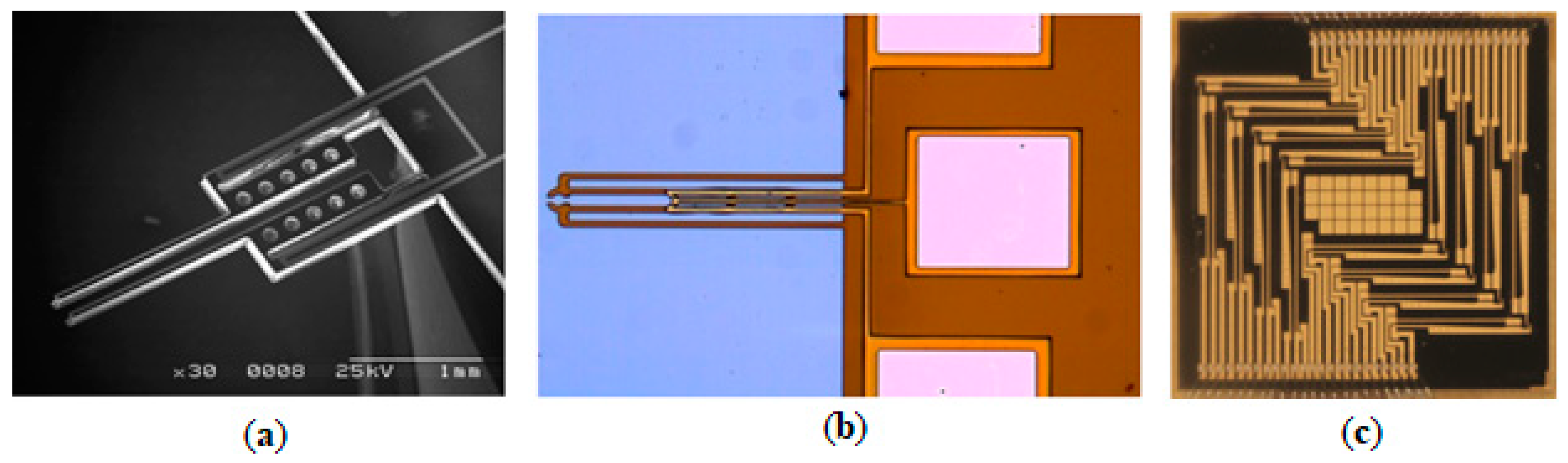
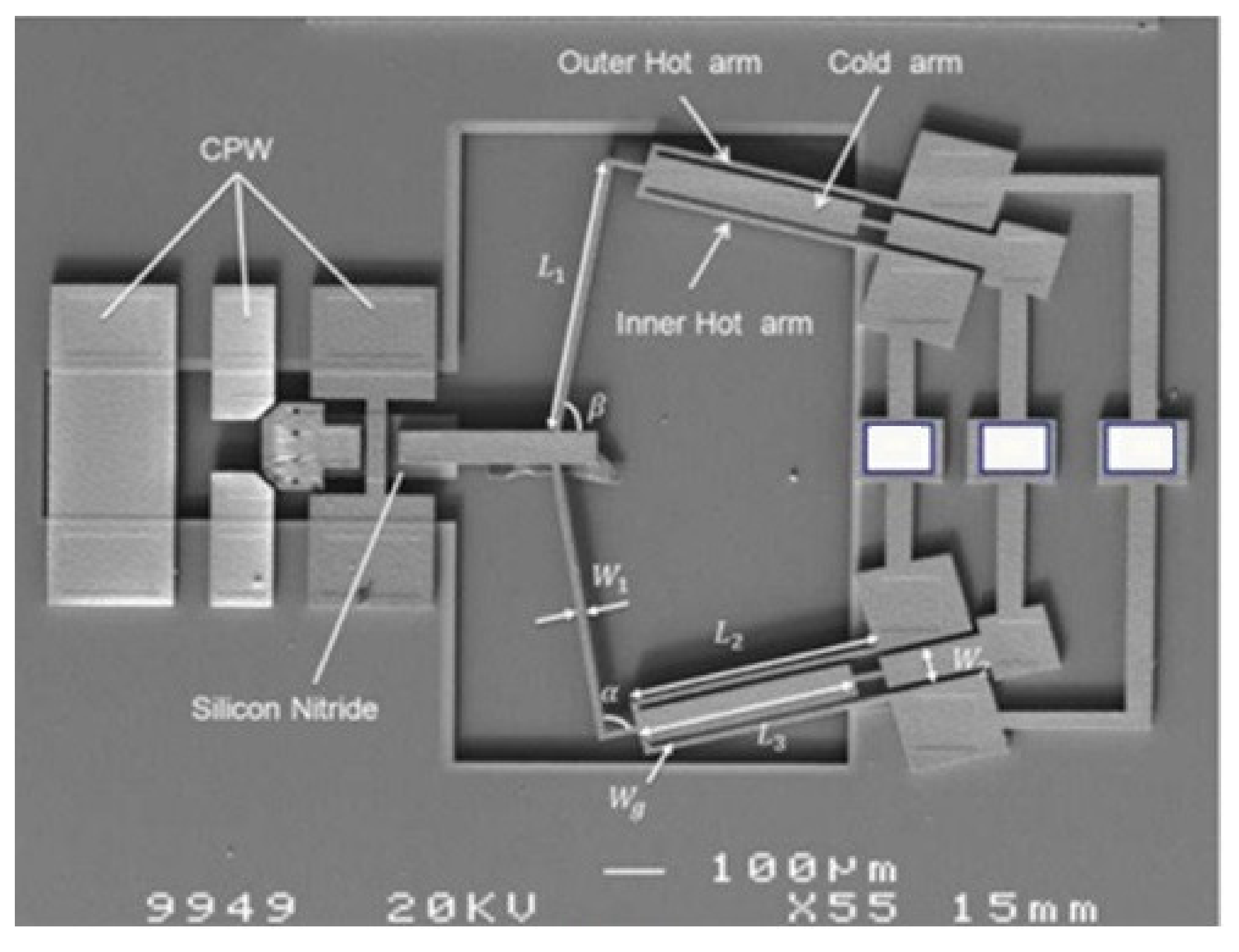
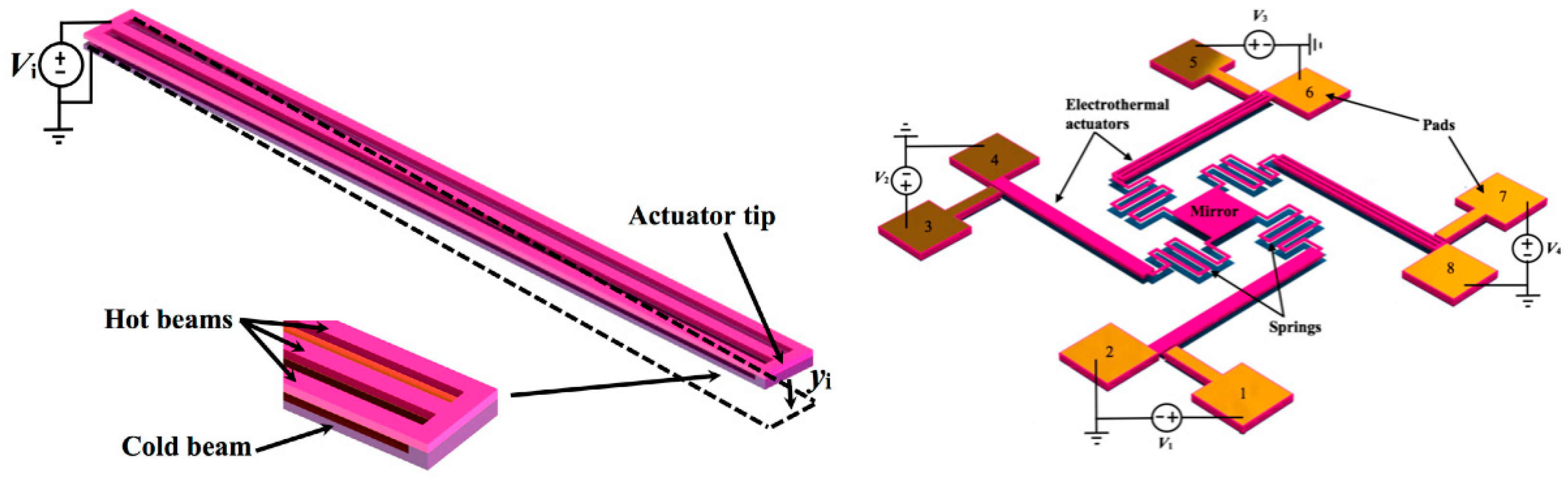
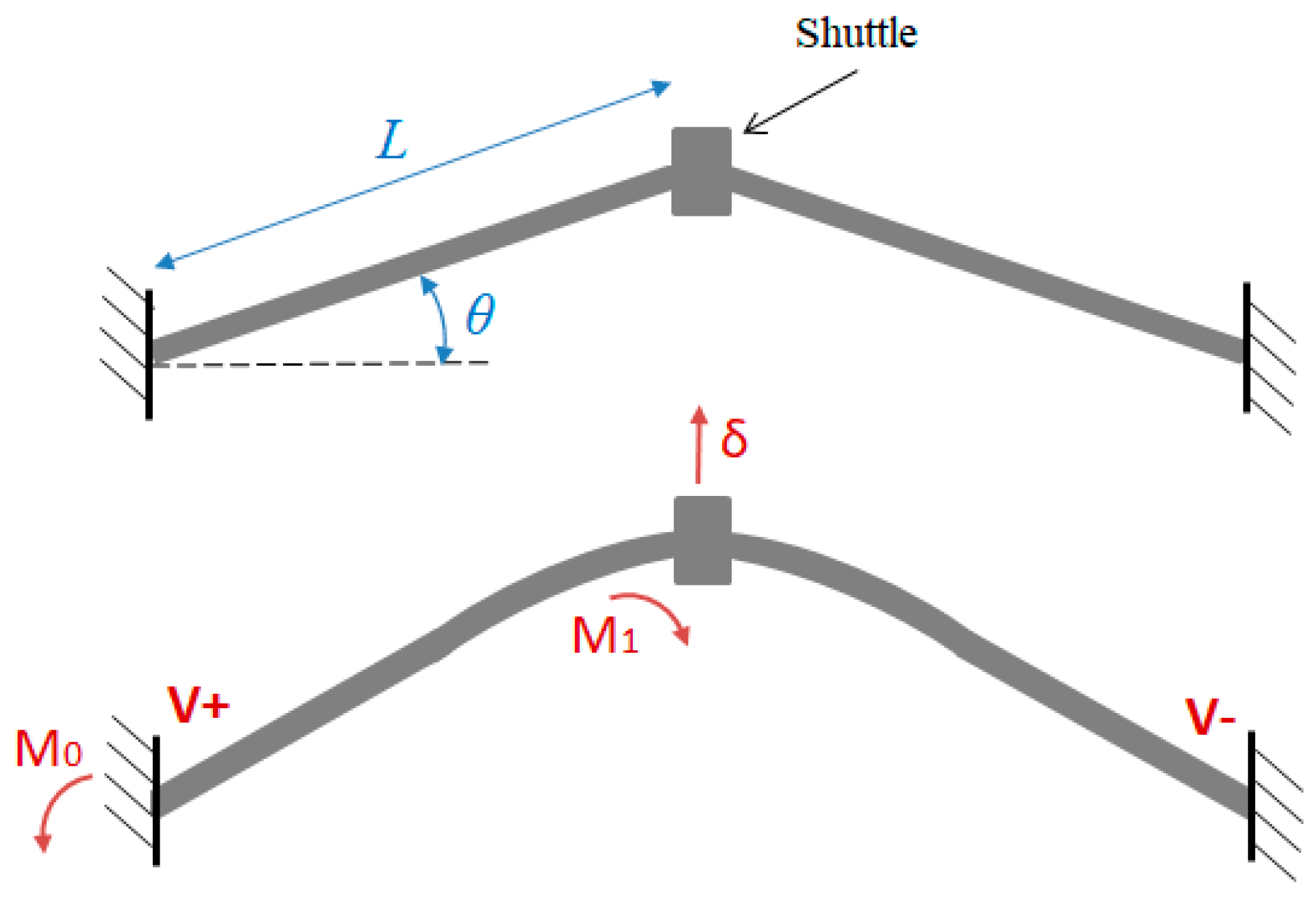
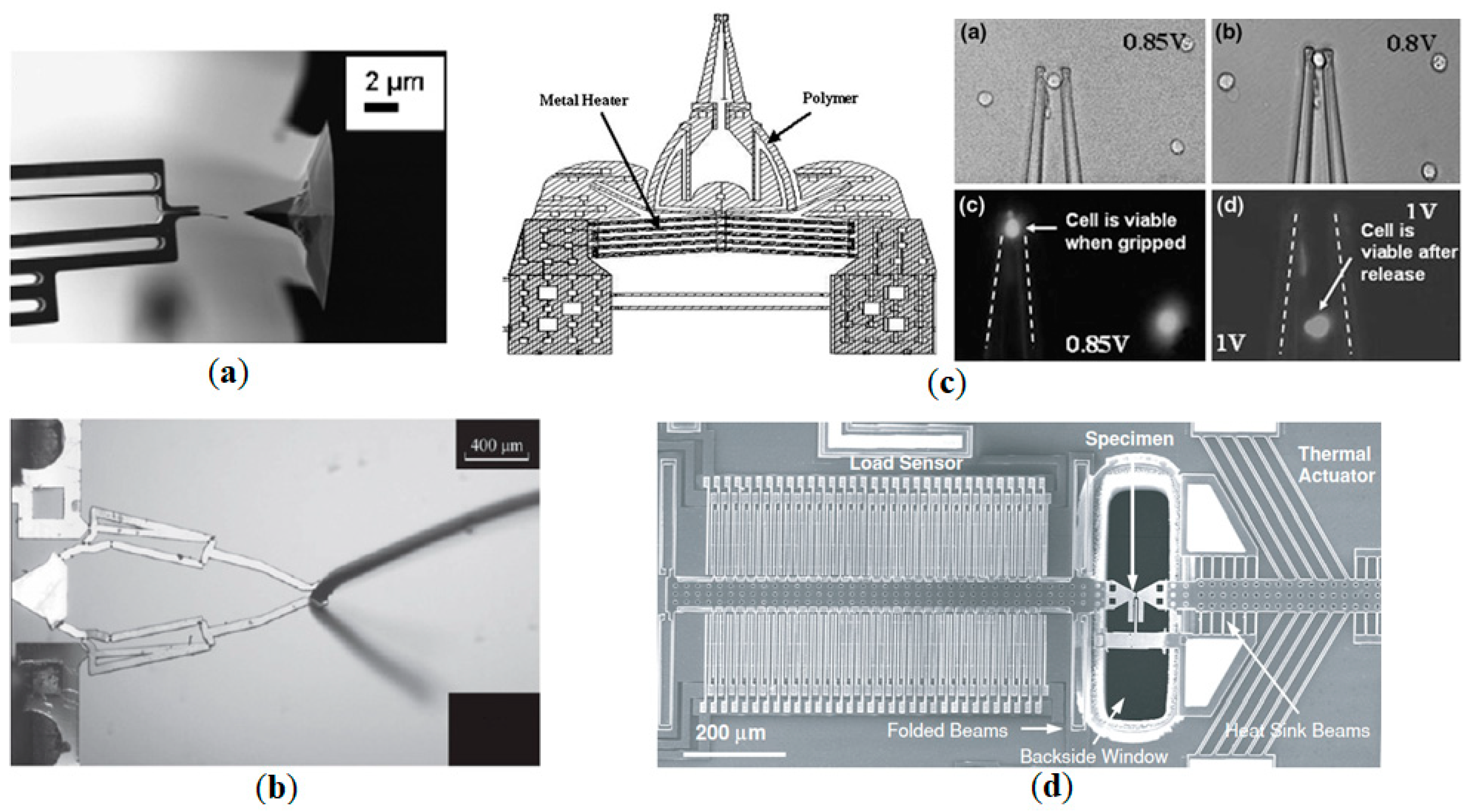
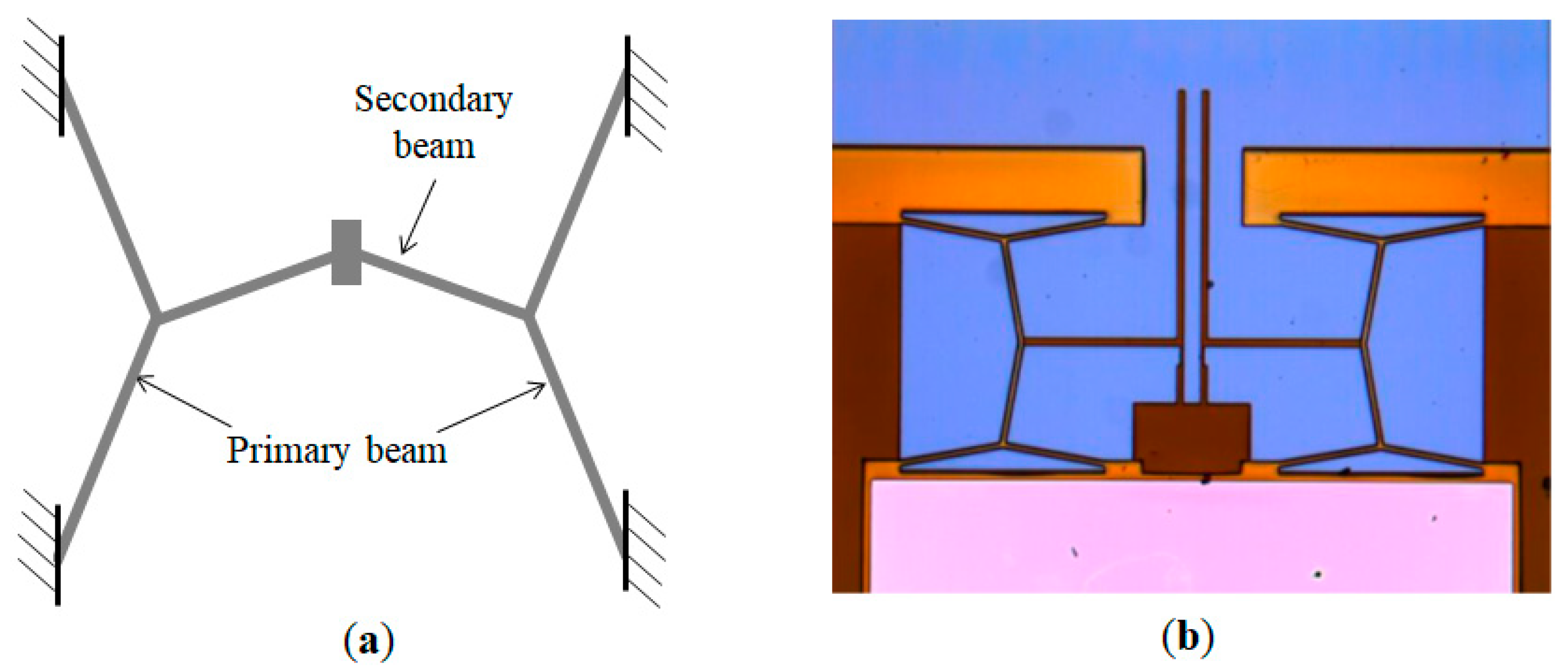
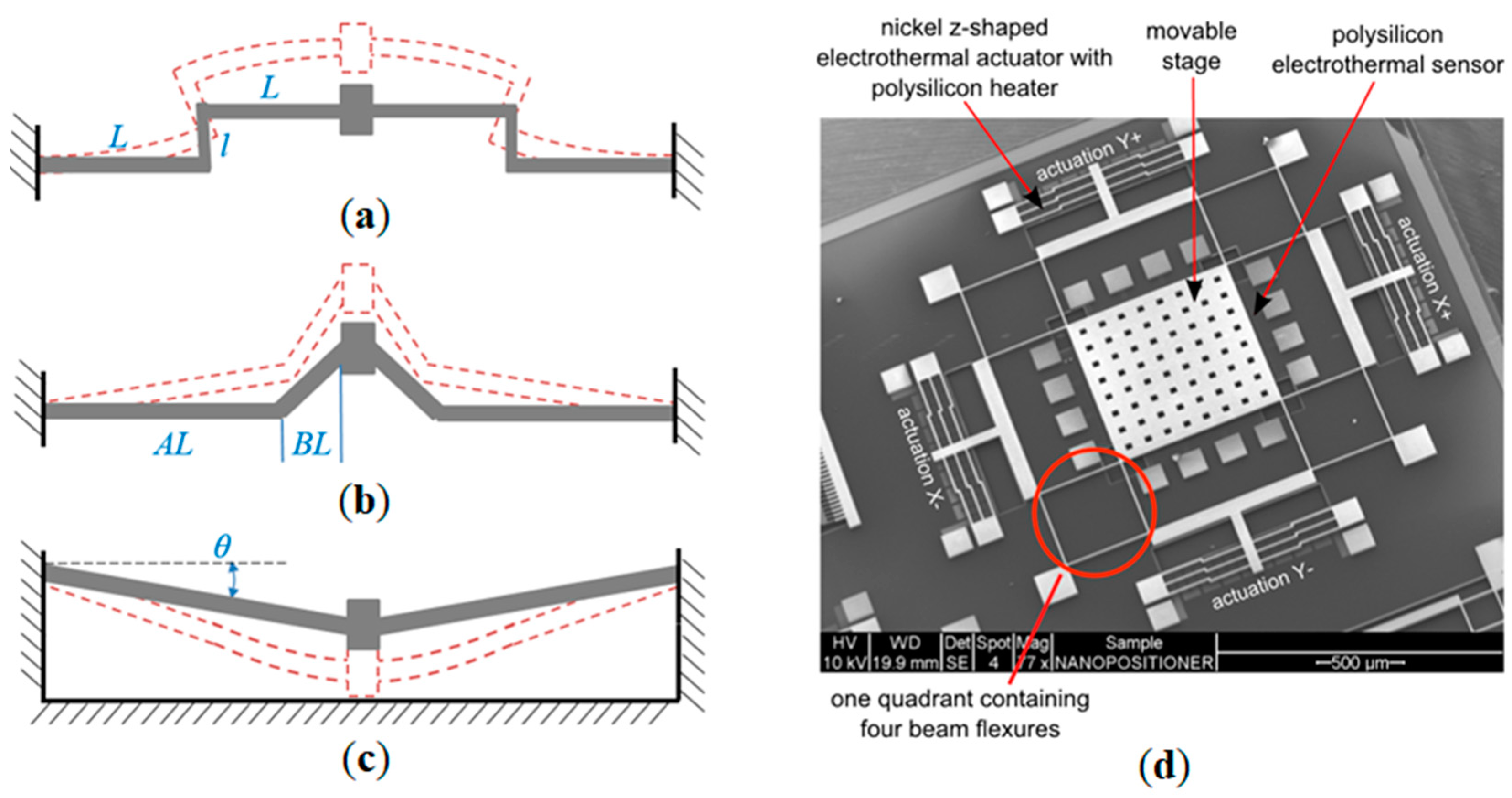
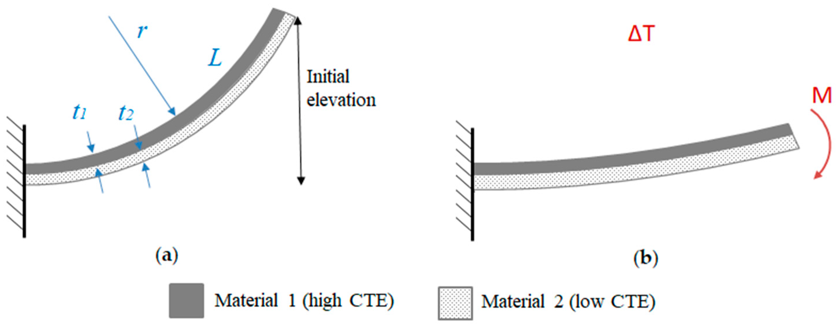
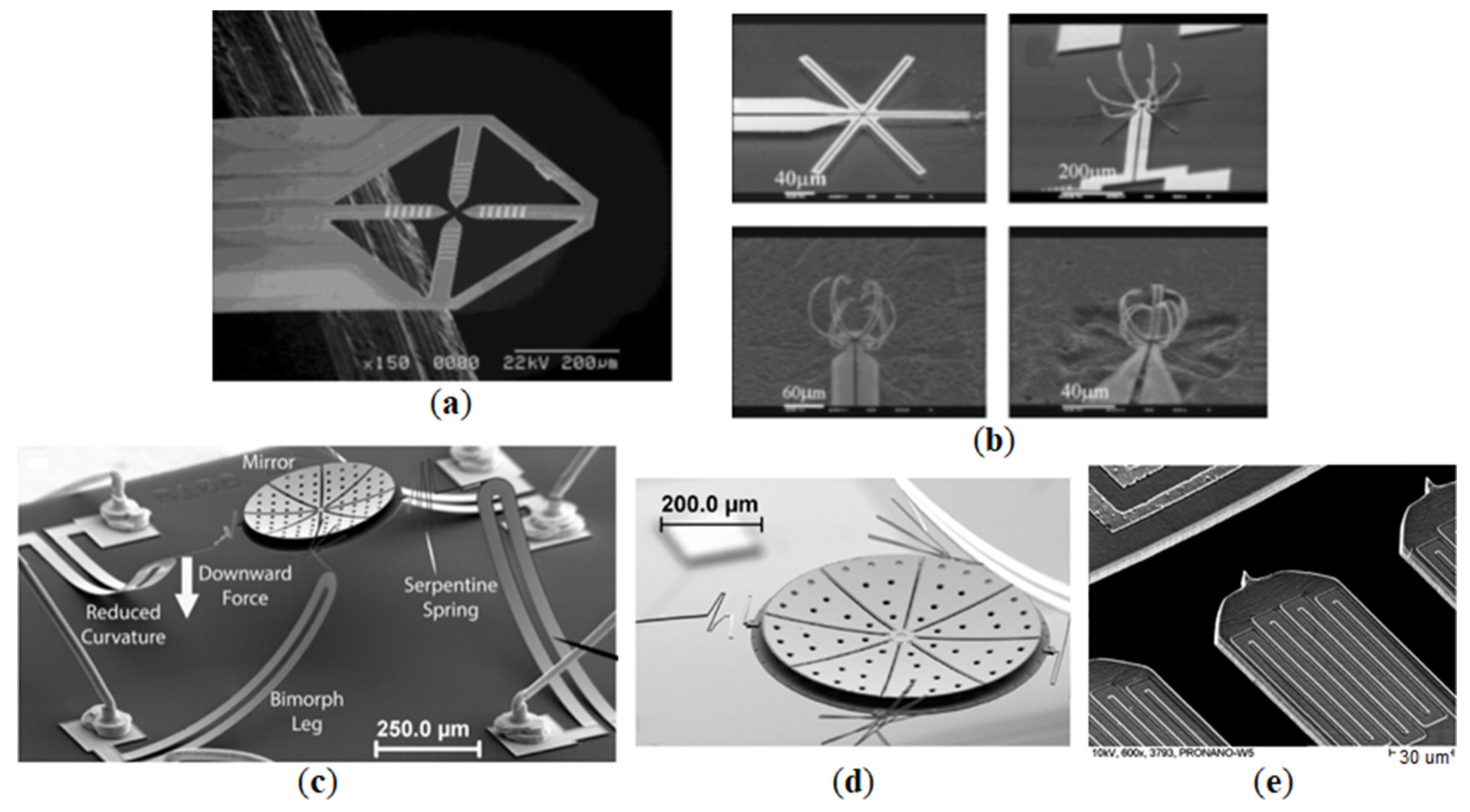
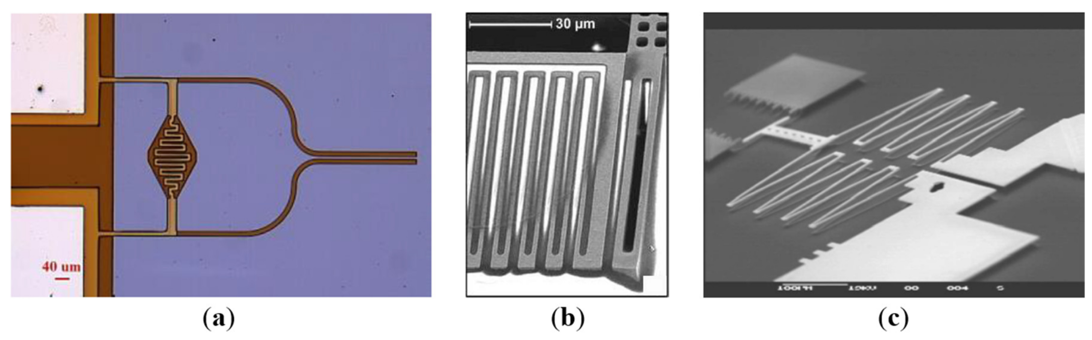
Table 1.
Summary of hot-and-cold-arm actuators and applications (x—maximum displacement demonstrated, u—corresponding driving voltage).
Table 1.
Summary of hot-and-cold-arm actuators and applications (x—maximum displacement demonstrated, u—corresponding driving voltage).
| Principle | Bi-directional | Material | x, µm | u, V | Application | Year | Figure | Ref. |
|---|---|---|---|---|---|---|---|---|
| different arm width | - | SU-8, Cr/Au | 11 | 2 | microgripper | 2004 | - | [4,38] |
| polySi | 9.1 | 14 | microgripper | 2015 | - | [66] | ||
| different arm length | - | polySi | 20 | 10 | microgripper | 1997 | - | [22] |
| ETC | - | Si (SOI) | – | – | micromanipulator | 2001 | - | [23] |
| selective doping | - | Si (SOI) | ~17 | ~8 | actuator | 2001 | - | |
| modified resistivity | - | Si, Au | 120 | 50 | bistable relay | 2005 | - | [26] |
| folded heater | - | SU-8, Au | 262 | 1.94 | microgripper | 2007 | Figure 2a | [35] |
| - | Ni, polySi | 71, 41 | 24, 20 | distribution frame | 2016 | Figure 2c | [37] | |
| meander heater | - | SU-8, Cr/Au | ~9.6 | ~0.25 | microgripper | 2008 | - | [43] |
| inclined/curved arm | - | SU-8, Cr/Au | ~14.3 | ~0.25 | microgripper | 2009 | - | [44] |
| - | Ni | – | – | actuator | 2010 | - | [46] | |
| - | SU-8, Cr/Au | 8 | 0.7 | microgripper | 2013–17 | - | [47,48] | |
| “skeletal” | - | SU-8, Cr/Au | 17–20 | 0.65 | microgripper | 2014–17 | Figure 2b | [36,49] |
| three-beam | possible | Si, Au | 5 | 5 | microgripper | 2006–11 | - | [39,40,41,42] |
| possible | SU-8, Pt/Ti | 100 | 10 | microgripper | 2004 | - | [59] | |
| yes | Au | 4 | 0.23 | microgripper | 2005 | - | [60] | |
| yes | polySi | ~4 | ~8–9 | microgripper | 2008 | - | [61] | |
| - | polySi | ~3.5 | 6 | RF latch | 2015 | - | [55] | |
| yes | MetalMUMPS | – | 0.55 | RF switch | 2013 | Figure 3 | [58] | |
| tethered | - | Si (SOI) | >20 | 5 | optical attenuator | 2004 | - | [56] |
| coupled | yes | Si, Ni | 187.2 | – (1.6 W) | opt. fiber switch | 2000 | - | [62] |
| kinematic | yes | SUEX, Al | 177.1, 119 | – (54.8 mW) | position. platform | 2016 | - | [63] |
| out-of-plane | yes | Si | 6–7 | 5 | actuator | 2003 | - | [64] |
| - | polySi | 10.3 | 2.5 | micromirror | 2017 | Figure 4 | [65] |
Table 2.
Summary of chevron actuators and applications (x—maximum displacement demonstrated, u—corresponding driving voltage).
Table 2.
Summary of chevron actuators and applications (x—maximum displacement demonstrated, u—corresponding driving voltage).
| Principle | Material | Application | x, µm | u, V | Year | Fig. | Ref. |
|---|---|---|---|---|---|---|---|
| V-shape | Si (SOI) | 2D positioner | ~19 | >14 | 2003 | - | [70] |
| Ni | microgripper | 30 ± 4 | ~1.15 (260 mA) | 2005 | - | [69] | |
| Si | microgripper | 1.5–2 | – (8 mA) | 2008 | Figure 6a | [71] | |
| Si (SOI) | microgripper | 67 | 10 | 2008 | - | [82] | |
| SU-8, Au | microgripper | 10 | <1 | 2008 | Figure 6c | [79] | |
| Si | microgripper | 6–7 | 4 | 2010 | - | [73] | |
| Ni (MUMPs) | microgripper | 79 | 0.7 | 2011 | - | [72] | |
| SU-8, Cu | microgripper | 71.5 | 0.195 | 2011–13 | Figure 6b | [76,81] | |
| Ni | microgripper | 1.13 | 0.09 | 2014 | - | [75] | |
| SU-8, Cr/Au | microgripper | 40 | – (25 mA) | 2016 | - | [77] | |
| polySi | microgripper | 19.2 | 1 | 2016 | - | [78] | |
| SU-8, Au | microgripper | 70.5 | 0.74 | 2017 | - | [74] | |
| MUMPs | MEMS material testing | ~0.8 | – (15 mA) | 2005 | Figure 6d | [80] | |
| polySi | RF switch | – | 5 | 2009 | - | [83] | |
| Ni | RF switch | 8 | 0.07 | 2013 | - | [84] | |
| Ni | MEMS gyroscope | 18.6 | 0.2 | 2018 | - | [85] | |
| cascaded | polySi | rotary micro-engine | 33.4 | 14.4 | 2001 | - | [89] |
| Ni | ‘inchworm’ micro-engine | 32–40 | 1 | 2001 | - | ||
| SU-8, Cr/Au | microgripper | 50 | – (26 mA) | 2016 | Figure 7b | [88] | |
| Ni | actuator | 18 | 1.5 | 2008 | - | [90] | |
| Z-shape | Si | microgripper | 80 | 6 | 2016 | - | [93] |
| Ni (MUMPs) | 2D nanopositioner | ±5 | ±150 | 2014 | Figure 8d | [94] | |
| kink-shape | polySi (MUMPs) | actuator | ~8 | 8 | 2012 | Figure 8b | [95] |
| out-of-plane | Al | MEMS switch | ~0.16 | – | 2018 | Figure 8c | [96,98] |
Table 3.
Summary of a typical application of bimorph actuators (x—maximum displacement demonstrated, u—corresponding driving voltage).
Table 3.
Summary of a typical application of bimorph actuators (x—maximum displacement demonstrated, u—corresponding driving voltage).
| Principle | Material | Application | x, µm/° | u, V | Year | Fig. | Ref. |
|---|---|---|---|---|---|---|---|
| Out-of-plane | Si, SiO2, Al | 2-finger microgripper | 140 | – (80 mW) | 1996 | - | [5] |
| Si, SiO2, Au/Cr | 4-finger microgripper | ~35 | 0–30 | 2011 | Figure 10a | [110] | |
| Pt, parylene | microcage | 90° | 2.5 | 2004 | - | [115] | |
| Ni, DLC | microcage | ~90° | – (<20 mW) | 2005 | Figure 10b | [111] | |
| SU-8, Al, DLC | microcage | ~80° | 3.2 (<9 mW) | 2006 | - | [114] | |
| SiO2, polySi, Al (CMOS) | micromirror (OCT) | 40°, 25° | 15, 17 | 2004 | - | [117] | |
| Si, SiO2, Al | micromirror | 10° | 0–1.4 | 2005 | - | [118] | |
| Al, polySi, SiO2 | micromirror | 56 | 3–7 | 2006 | - | [120] | |
| Si, SiO2, Al | micromirror (endoscopic) | 17° | 1.6 | 2007 | - | [123] | |
| SiO2, Pt, Al | micromirror (OCT) | 621 | 5.3 | 2008 | - | [119] | |
| SiO2, Pt, Al | micromirror | ±30°, 480 | ±4, 8 | 2009 | - | [121] | |
| SiO2, W, Al | micromirror (endoscopic) | ±11°, 227 | 0.6, 0.8 | 2012 | - | [116] | |
| Cu, W, SiO2 | micromirror | ±13°, 169 | 2.3 | 2015 | - | [122] | |
| polySi, Au | varifocal micromirror | ±40°, 300 | – (90 mW) | 2015 | Figure 10c,d | [112] | |
| Al, SiO2, Si | AFM probe | 3.6 | – (30 µW) | 2003 | - | [125] | |
| Si3N4, Cr, W | SPN probe | 16.9 | – (5.5 mA) | 2010 | - | [124] | |
| Si, SiO2, Al | AFM/SPN probe | - | 50 | 2008 | Figure 10e | [113] | |
| Al, Si, SiO2/Si3N4 | AFM/SPN probe | 10 | – (24 mW) | 2016 | - | [126] | |
| Si, Au | DPN probe | 28 | – (17.57 mW) | 2004 | - | [127] | |
| In-plane | Si, Al | actuator | 4.5 | – (3 mW) | 2001 | - | [107] |
| SiO2, Al (CMOS) | actuator | 2.1 | – | 2008 | - | [108] | |
| Al, SiO2, Pt | actuator | 135 | 3.8 | 2013 | - | [109] |
Table 4.
Summary of unconventional electrothermal actuators (x—maximum displacement demonstrated, u—corresponding driving voltage).
Table 4.
Summary of unconventional electrothermal actuators (x—maximum displacement demonstrated, u—corresponding driving voltage).
| Principle | Direction of Deflection | Material | Application | x, µm | u, V | Year | Fig. | Ref. |
|---|---|---|---|---|---|---|---|---|
| expanding beams | linear | Ni | microgripper | 60 ± 4 | ~1.15 (190mA) | 2005 | - | [69] |
| linear | SU-8, Cr/Cu | microgripper | ~100 | 0.1–0.5 | 2011 | - | [131] | |
| linear | SU-8, Cr/Au | microgripper | 11 | 0.65 | 2017 | Figure 11a | [48,128] | |
| Si/polymer stack | linear | Si, SU-8, Al | 2D microgripper | 8, 13 | 2 | 2007 | - | [132] |
| linear | Si, SU-8, Al | 2D microgripper | 17, 11 | 2.5 | 2008 | - | [133] | |
| lateral | Si, SU-8, Al | microgripper | 32 | 4.5 | 2008 | Figure 11b | [129] | |
| out-of-plane | Si, SU-8, Al | actuator | 31 | 5 | 2008 | - | [134] | |
| microspring | linear | Ni, SiO2 | actuator | 33.7 | 0.4 | 2004 | Figure 11c | [130] |
| linear | Ni | microgripper | 94.9 | 1.6 | 2006 | - | [135] | |
| X and Y DOF | 2D | Si (SOI) | microgripper | 38.4, 11.6 | ~40 | 2005 | - | [136] |
| folded buckling | lateral | Si, Cr/Au | opt. fiber alignment | 26 | ~10 | 2004 | - | [137] |
| combined | combined | Ni (MUMPs) | microgripper | 173 | 1 | 2011 | - | [46] |
| linear | polySi, Al | MEMS switch | 2.7 | 1 | 2010 | - | [138] |
© 2019 by the authors. Licensee MDPI, Basel, Switzerland. This article is an open access article distributed under the terms and conditions of the Creative Commons Attribution (CC BY) license (http://creativecommons.org/licenses/by/4.0/).
Share and Cite
MDPI and ACS Style
Potekhina, A.; Wang, C. Review of Electrothermal Actuators and Applications. Actuators 2019, 8, 69. https://doi.org/10.3390/act8040069
AMA Style
Potekhina A, Wang C. Review of Electrothermal Actuators and Applications. Actuators. 2019; 8(4):69. https://doi.org/10.3390/act8040069
Chicago/Turabian StylePotekhina, Alissa, and Changhai Wang. 2019. "Review of Electrothermal Actuators and Applications" Actuators 8, no. 4: 69. https://doi.org/10.3390/act8040069
Note that from the first issue of 2016, this journal uses article numbers instead of page numbers. See further details here.