Pneumatic Hyperelastic Actuators for Grasping Curved Organic Objects


1
Department of Mechanical and Materials Engineering, The University of Western Ontario, London, ON N6A 5B9, Canada
2
Vineland Research and Innovation Centre, Vineland Station, ON L0R 2E0, Canada
*
Author to whom correspondence should be addressed.
Actuators 2019, 8(4), 76; https://doi.org/10.3390/act8040076
Submission received: 8 July 2019
/
Revised: 17 September 2019
/
Accepted: 1 November 2019
/
Published: 5 November 2019
Abstract
:Soft robotic grippers often incorporate pneumatically-driven actuators that can elastically deform to grasp delicate, curved organic objects with minimal surface damage. The complexity of the actuator geometry and the nonlinear stress–strain behavior of the stretchable material during inflation make it difficult to predict actuator performance prior to prototype fabrication. In this work, a scalable modular elastic air-driven actuator made from polydimethylsiloxane (PDMS) is developed for a mechanically compliant robotic gripper that grasps individual horticultural plants and fungi during automated harvesting. The key geometric design parameters include the expandable surface area and wall thickness of the deformable structure used to make contact with the target object. The impact of these parameters on actuator displacement is initially explored through simulation using the Mooney–Rivlin model of hyperelastic materials. In addition, several actuator prototypes with varying expandable wall thicknesses are fabricated using a multistep soft-lithography molding process and are inserted in a closed ring assembly for experimental testing. The gripper performance is evaluated in terms of contact force, contact area with the target, and maximum payload before slippage. The viability of the gripper with PDMS actuators for horticultural harvesting applications is illustrated by gently grasping a variety of mushroom caps.
1. Introduction
Soft, mechanically compliant robotic grippers can elastically deform to grasp irregularly shaped organic objects, such as strawberries, small citrus fruits, and mushrooms. In contrast to industrial rigid robotic end effectors that apply point forces on a target, soft grippers can distribute the contact forces over a broader surface area [1], thereby minimizing contact damage to delicate surfaces and structures. Pneumatic actuation [2,3,4,5,6,7] is commonly used because air is nearly inviscid, and compressed air can be stored and dispensed at precise pressure levels. During operation, the applied pressurized air causes the inflation and deformation of one or more inner cavities (i.e., chambers) embedded in the actuators of the grasping mechanism. These air-driven, soft actuators often have complex geometries and are fabricated from hyperelastic materials, such as synthetic rubbers or silicone polymers [3], which exhibit nonlinear stress–strain properties, making it difficult to precisely predict the actuator’s behavior. The inherent nonlinearity of the elastomeric material becomes a critical design consideration when developing a soft gripper for commercial applications such as automated harvesting of small horticultural crops.
Various soft, air-driven actuators have been reported in the literature, and they are based on several complementary operating principles [2,3,4,5,6,7,8,9,10]. One of the simplest and earliest actuators is the Pneumatic Artificial Muscle (PAM), where a closed inflatable membrane is inflated with pressurized air to generate a linear and unidirectional axial force [5]. A variant of the PAM is the McKibben actuator, which surrounds the closed membrane with a braided sleeve [6,7]. When pressurized with air, the volume of the tube increases radially while the overall actuator length decreases. It is also possible to introduce a bending motion by adding an inextensible layer along the length of a McKibben actuator. Studies have shown that the bendable McKibben actuator operating under 500 kPa of air pressure can produce a contact force of approximately 42 N [7]. The PneuNet [2] is another popular bendable, soft actuator that consists of a series of air chambers connected by a long channel. To control the direction of movement or bending, the stretchable elastomeric structure has one or more surfaces bonded to an inextensible material such as paper, cloth, or fiber mesh. Although visually impressive, the bulky and ultrasoft PneuNet uses low air pressures (e.g., 72 kPa) and thus generates very small contact forces (e.g., 1.4 N) [2]. In another type of bending actuator, researchers have used a variety of wrapping fiber reinforcements, including Kevlar threads, nylon, and string [8,9]. Incorporating fiber reinforcements in semicircular tube-shaped soft actuators, Miron et al. [8] use an increased air pressure to 275 kPa and created forces in the range of 20 to 28 N.
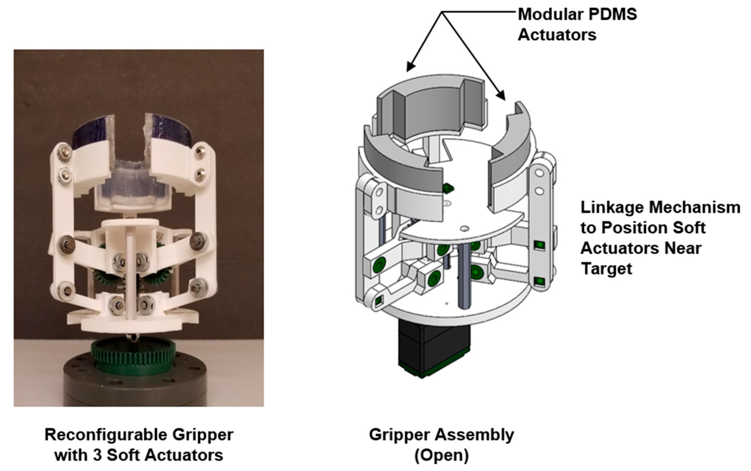
In general, pneumatically-driven expandable, soft actuators are based on the notion of stretchable elastomeric structures with inflatable air cavities that incorporate inextensible walls or surfaces that guide movement, such as active surface deformation or bending motion. Important design considerations include selecting an appropriate elastomeric material with predictable properties, developing a viable geometry for the required movement, restricting the actuator’s degrees-of-freedom (DoF) to achieve the desired contact forces, and ensuring ease of fabrication and reproducibility. The intended application also imposes constraints on the actuator design. For example, many of the biologically inspired soft, bendable actuators [2,3,4,5,6] are not suitable for horticultural applications, because the designs incorporate too many DoF and do not take into account spatial constraints imposed by the work environment. To address these practical concerns, the air-driven, soft gripper described in this paper is comprised of three modular hyperelastic polydimethylsiloxane (PDMS) actuators inserted in a closed ring assembly (Figure 1).
While a similar closed monolithic design inspired by the mouth of a sea lamprey has been described in the literature [10], the individual actuators proposed in this work have a scalable modular structure that enable multiple discrete units to be inserted in the gripper assembly or attached to the tips of discrete robotic fingers for controlled “soft touch” applications. To reduce the complexity and ensure that specific design parameters can be directly related to actuator displacement, only a single deformable surface or wall of the elastomeric air chamber is allowed to make contact with the target object. This is achieved, in part, by a rigid housing structure that restricts the material expansion along the desired working surface (Figure 1b,c). Furthermore, the selected hyperelastic material is polydimethylsiloxane (PDMS). This elastomer in its commercial form (e.g., Sylgard 184) has well-established tensile and shear properties [11,12,13,14,15], and it can be easily molded into a variety of shapes using soft-lithography and low-temperature molding processes.
Section 2 introduces the design of the modular elastic actuators embedded in the rigid gripper assembly. The discussion focuses on the key geometric dimensions and role of the selected PDMS elastomer. In addition, a COMSOL simulation study is used to relate key geometric parameters of the expandable surface to expected actuator displacement. The stress–strain behavior of the PDMS device is simulated using the Mooney–Rivlin model for hyperelastic materials [16,17]. The multistep soft lithography molding process for fabricating the soft actuators is briefly summarized in Section 3. Section 4 describes several experiments used to characterize the prototype performance. Specifically, the physical actuator displacement for three different wall thicknesses and under various applied pressures are investigated. In addition, the measured contact forces, contact area, and slip test payload are acquired for the three selected wall thicknesses. The viability of the soft gripper with PDMS actuators for horticultural harvesting applications is illustrated by gently grasping a variety of mushroom caps. Finally, important design guidelines are summarized and future work is discussed.
2. Hyperelastic Pneumatic Actuators
2.1. Geometric Design of Elastomeric Actuator
A pneumatic gripper comprised of three compact PDMS actuators (Figure 2a) was developed for grasping irregular-shaped organic objects during automated harvesting [18]. Each constituent actuator has a curved geometry (Figure 2b), with only one deformable concave wall that expands toward the center of the gripper assembly during pressurization (Figure 2c). Similar to bending actuators, the proposed design uses a strain-limiting layer to prevent unwanted deformation of the actuator’s rear surface (Figure 2c). However, there is no strain-limiting material embedded in the wall of the expandable surface. The modular single-DoF actuator is designed for functional simplicity, ease of fabrication and assembly, reliability, and repeatable performance. In addition, the design enabled a realistic model of the stress behavior to be simulated using COMSOL Multiphysics software, in order to predict the impact of the expandable wall dimensions on the gripper’s performance during air inflation.
The dimensional parameters for the actuator correspond to the inflatable chamber height and depth (), the angle of the actuator’s arc , the thickness of the outer wall attached to the rigid housing unit , and the thickness of the expandable deformable inner wall . The majority of chamber expansion will occur along the inner concave wall; therefore, it is defined as the actuator’s primary active deformable wall. When inflated with pressurized air, the freely moving expandable primary wall produces a center displacement with a predictable contact pressure . The displacement and contact pressure are dependent upon both the actuator’s chamber geometry and the applied air pressure input . The geometric parameters used to simulate and experimentally assess the performance of the proposed hyperelastic actuator are given in Table 1. Furthermore, the impact of these parameters will be evaluated over a range of low applied air pressures .
2.2. Hyperelastic Material—Polydimethylsiloxane
Pneumatically-driven soft actuators have been fabricated from a variety of commercially available silicone elastomers, like Ecoflex™ [2], DragonSkin™ [9], and premade tubes of commercial silicone [8]. Although these elastomeric materials are ultrasoft and can be molded into single and multichambered actuators, they were originally developed for cosmetic coverings on prosthetic devices or theatrical work. As a result, the manufacturers do not require precise control on the chemical composition, use ad hoc fabrication processes to create the base and curing agents, and produce an elastomer product where the material properties are often unpredictable [19] and must be experimentally characterized prior to any prototype fabrication. In contrast, polydimethylsiloxane (PDMS) is a flexible silicone-based organic polymer that is used extensively in scientific research due to its viscoelastic, thermosetting, and inert properties [11,12]. The predictable properties of PDMS make it a viable hyperelastic material for computational simulation on COMSOL Multiphysics software and enable the designer to develop a deeper understanding of the impact of geometric design parameters on actuator performance.
The PDMS material used in this research is Sylgard 184 (Sigma Aldrich) [13], which is commercially available as a monomer base and curing agent that, when mixed and thermally cured, becomes a solid elastomer. The mechanical properties of PDMS can be adjusted by varying the base/agent mixing ratio [14], curing temperature [13,15], and cure time. The established well-documented procedures for creating softer or harder PDMS elastomer structures provide control on the fabrication processes for creating functional soft hyperelastic pneumatic actuators. For the purposes of this research, a 10:1 base/curing agent mixing ratio is used with a thermal cure at ambient temperature for 48 h. An alternative elastomer comparable to PDMS, in terms of material properties, is RTV 615 Silicone [20].
2.3. Strain-Energy Function of Hyperelastic Material
The goal of the computational model is to investigate the impact of various design parameters and applied air pressure on the displacement of the expandable actuating surface . Since the stress–strain behavior of a hyperelastic material and associated structures is highly nonlinear, it is necessary to use a constitutive model for the computational simulations [16,17]. Suitable constitutive models can be derived from a strain-energy density function that represents the energy stored in the material per unit volume of the original geometry as a function of strain at that point in the material.
In this study, the Mooney–Rivlin model [16,17,21,22] was used to simulate the hyperelastic behavior of the pneumatically driven PDMS material. The generalized form of strain-energy density is given by:
where and are principal strain invariants, which are assumed to remain constant under a pure volume change. A third strain invariant is isolated as part of the elastic volume ratio , with . If the material is assumed to be incompressible then . The variables and are the shear and bulk moduli of the solid, respectively. The shear modulus value used for the COMSOL simulations is [21]. The variables and are material constants related to the distortional response [22]. As described by Holzapfel [17], the material constants are related to the shear modulus by . An approximation of can be made for rubber-like materials [16,17,23] to estimate the value of the material constants.
To satisfy both the shear moduli relation and approximation, the parameters in this study were set to and . Simulations with COMSOL Multiphysics also require the Poisson’s ratio, . Because the material is assumed to be incompressible, . However, this results in computation error and simulation failure. This was resolved by slightly modifying the Poisson’s ratio to 0.49. Separate tests were performed on standard tensile specimens to assess the mechanical properties of the PDMS material used in the prototype development. In general, the measured results were in agreement with the trends reported by Johnston et al. [13], with minor deviations arising from slight differences in the ambient curing temperature.
2.4. COMSOL Multiphysics Simulation and Analysis
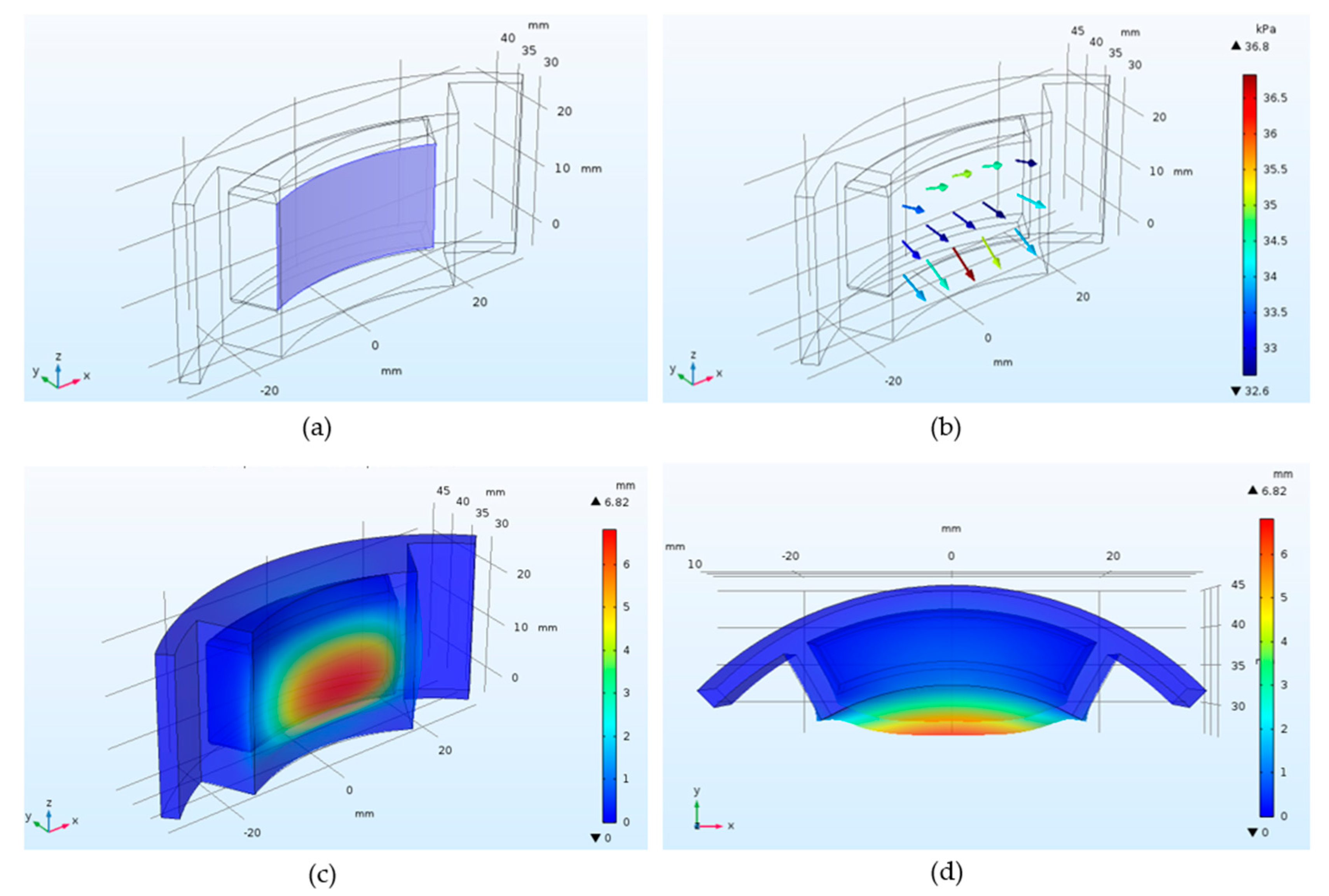
In this simulation study, the Structural Mechanics, Nonlinear Structural Materials, and Material Library modules of COMSOL Multiphysics software were used to analyze the hyperelastic properties of the PDMS device under varying conditions. In addition, SolidWorks LiveLink add-on was used to synchronize the SolidWorks CAD and finite element models with the COMSOL simulations. For the simulations, the modular actuator was modelled with a fixed constraint at the convex wall (Figure 3). Furthermore, the displacement data was solved at a point located in the center of the concave deformable wall. The total displacement at the point was determined by the components of the displacement field, and
Each simulation test started with the same initial conditions, and the structure was restricted so that the applied air pressure caused only the concave wall of the chamber to deform. In addition, the timed simulations were solved for 1 s of applied pressure. The dynamics of the hyperelastic structure during inflation were not investigated in this study.
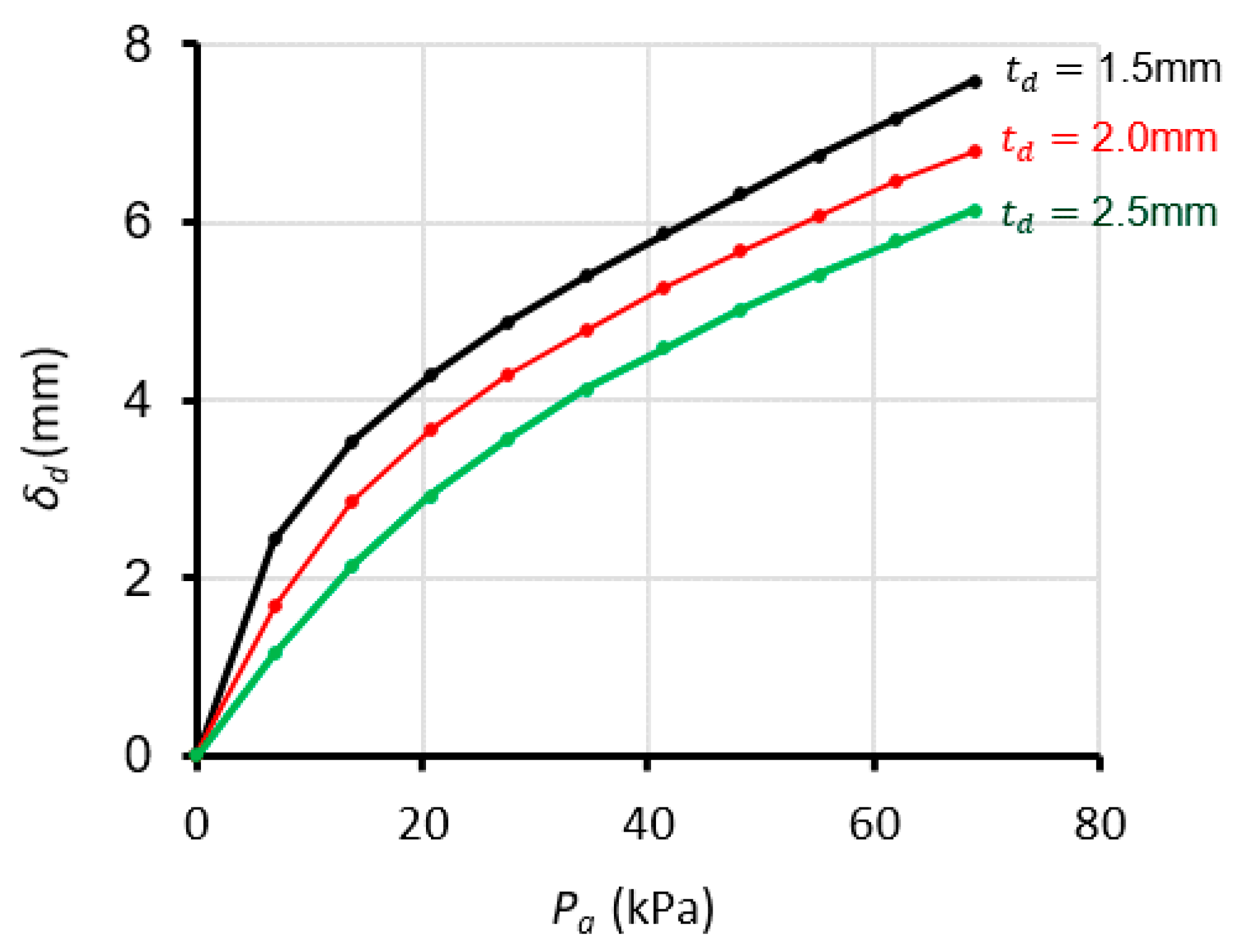
Simulations were first performed to examine the impact of applied pressure on the actuator deformation for three different wall thicknesses (i.e., ). The range of applied pressure is from 0 to 68.94 kPa (0 to 10 psi), and the expected displacement is shown in Figure 4. The results confirm that the thinnest wall exhibits the greatest displacement. Note that the rate in which the wall expands decreases at higher pressures because the PDMS structure is already stretched to near maximum.
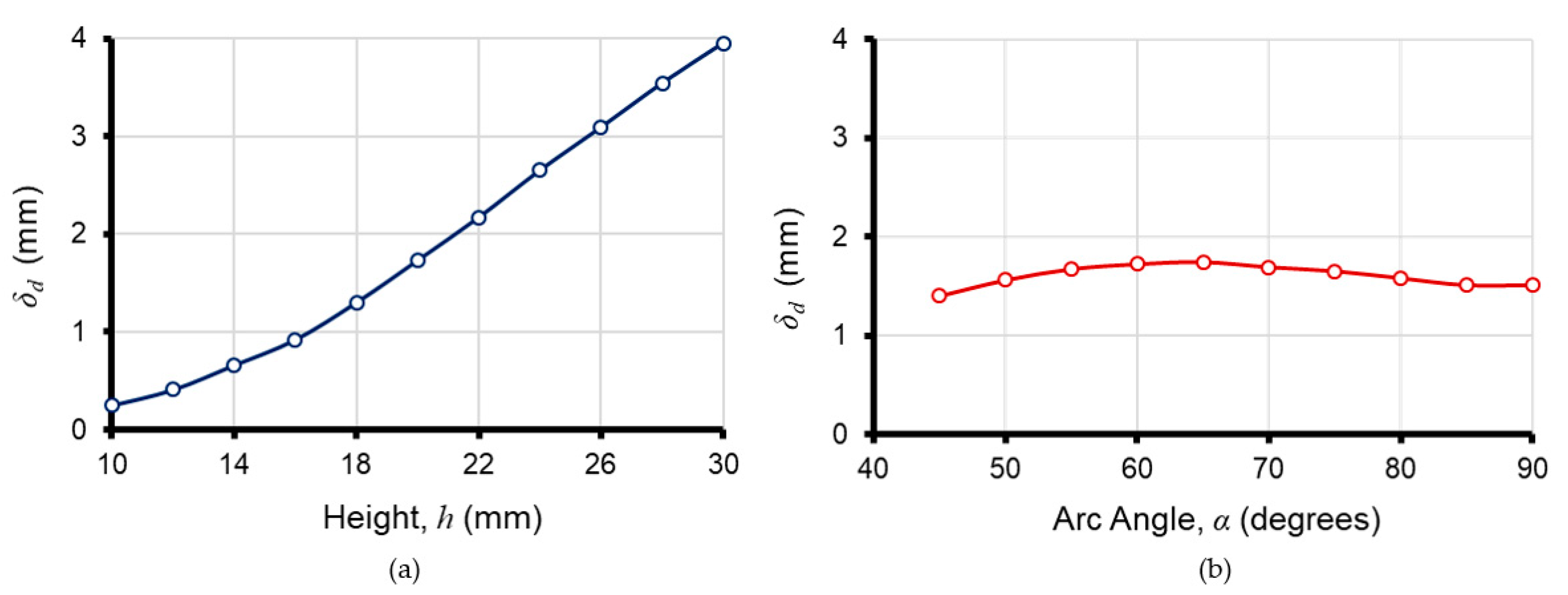
Another series of COMSOL simulations were performed to assess the impact of chamber height and actuator arc angle on the displacement of the actuating surface. These two parameters are used to define the size of the active surface when the actuator is inflated. In each case, the applied air pressure is 6.89 kPa (1 psi), and the thickness of the active wall is fixed at 2 mm. The results show a near linear change in displacement for increased actuator height (Figure 5a), while increasing the arc angle (Figure 5b) only has a minimal impact on the actuator displacement. Note that as the α increases, the active surface area of the actuator becomes bigger and modestly reduces the observed displacement when given the same internal pressure .
3. Fabrication of PDMS Actuators and Gripper Assembly
3.1. Actuator Fabrication
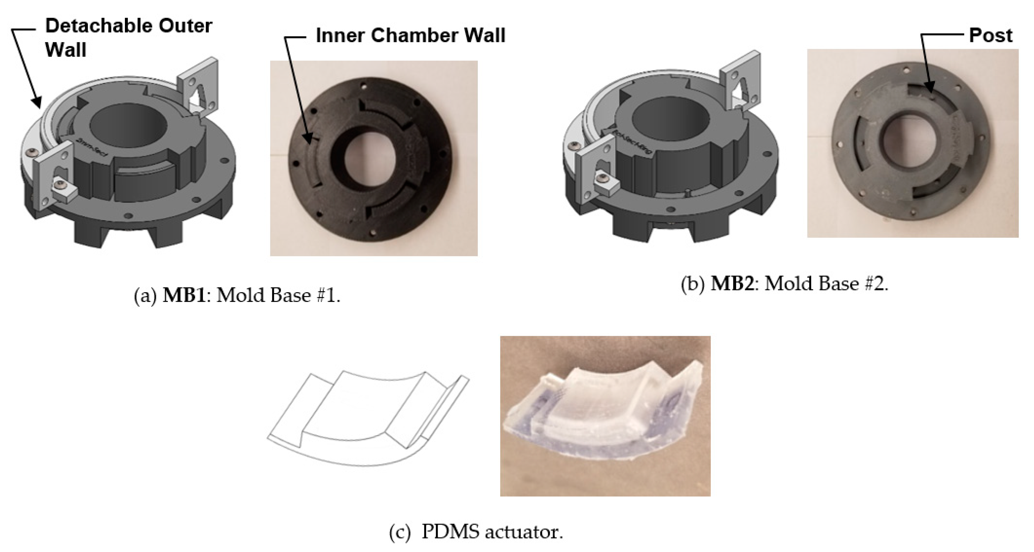
The hyperelastic PDMS actuators were fabricated using a multistep soft lithography molding process. The method requires two circular mold bases (MB1: mold base #1 and MB2: mold base #2) and a detachable outer wall, as shown in Figure 6, where each reusable mold assembly can produce up to three compact pneumatic actuators at a time. MB1 was used to form the majority of the part geometry with a single open exposed surface, while MB2 created the final surface used to close the pneumatic chamber for the actuators. The molds are designed for precise alignment during assembly and a combination of partial curing and adhesive bonding for assembling the discrete PDMS components (Figure 6c).
The key steps of the fabrication process are summarized in Figure 7. MB1 was first assembled by attaching the outer wall to the base and ensuring that there were no leaks along the joins (Figure 7a). Mixed PDMS prepolymer was then slowly poured into each of the actuator cavities (Figure 7b). Once filled, the assembly was placed in a vacuum chamber and fully degassed until no bubbles remained in the PDMS. After degassing the PDMS, the entire assembly was left to cure at ambient temperature for 48 h. Upon completion of curing, the outer walls attached to MB1 were removed, and the cured PDMS part was carefully extracted (Figure 7c). The bottom section of MB2 was then partly filled with PDMS (Figure 7d), degassed, and partially cured for 24 h. Typically, the thickness of the layer would be half the height of the post located at the center of MB2. The post forms the through-hole on the bottom PDMS layer, which becomes the air inlet for the assembled actuator. The process of partially curing allows the PDMS part to reach a solid state but remain bondable to another PDMS structure. To ensure a strong bond between the discrete molded parts, the remainder of the bottom section (slightly below the height of the central post) was filled with PDMS prepolymer and further degassed to eliminate bubbles in the polymer. The fully-cured PDMS part previously extracted from MB1 was then carefully aligned and placed over the uncured PDMS layer (Figure 7e). Light pressure was applied to the part in order to form a tight seal for the bonding process. To ensure that the assembly remained in place during the curing process, the outer walls were attached to the base of MB2. The completed MB2 assembly was then left to cure at ambient temperature for 48 h, after which it was taken apart and the finished PDMS geometry was removed (Figure 7f). Finally, a strip of synthetic fiber mesh was adhered to the convex surface of the actuator geometry with a thin coating of more prepolymer. This formed the strain-limiting, inextensible layer of the actuator. The synthetic fabric mesh allowed uncured PDMS prepolymer to seep through the fiber structure, fully bonding the layer to the PDMS geometry and preventing delamination.
3.2. Soft Gripper Assembly
Three identical actuators were simultaneously fabricated using the molding procedure described in Section 3.1 and then inserted into a 3D printed housing unit to form a circular ring-like gripper. The actuators are bonded to the housing unit with a thin layer of uncured prepolymer. The rigid ring has inlets that allow polyurethane tubing to connect to the actuators. A coupling extension connects the gripper ring to a manipulator arm. It also adds clearance between the arm and the gripper ring. All rigid structural components of the gripper housing unit and robot attachment are made of ABS (acrylonitrile butadiene styrene). The ring structure can hold the actuators of varying chamber heights and arc angles, but all experiments focused on the thickness of the expandable inner concave wall. The ABS ring weighed approximately 34 g, and each actuator weighed approximately 14 g. In total, each gripper weighed approximately 76 g.
4. Experimental Results and Discussion
A series of experiments were performed on individual PDMS actuators and the multiactuator gripper assembly. In all cases, the chamber height was fixed at and the arc angle was set at . The tests examined the actuator displacement , contact forces , contact area , and mass payload slippage for three different wall thicknesses . Finally, the viability of the proposed PDMS actuators for grasping and holding fragile objects (i.e., mushroom tops) is briefly explored. Some discrepancies will always exist between experimentally measured values and simulations, due to limitations in fabrication and in-situ measurements. In addition, experiments provide new empirical data whereas simulations do not. Rather, they produce results that are influenced by the conditions implemented within the model.
4.1. Measured Actuator Displacement
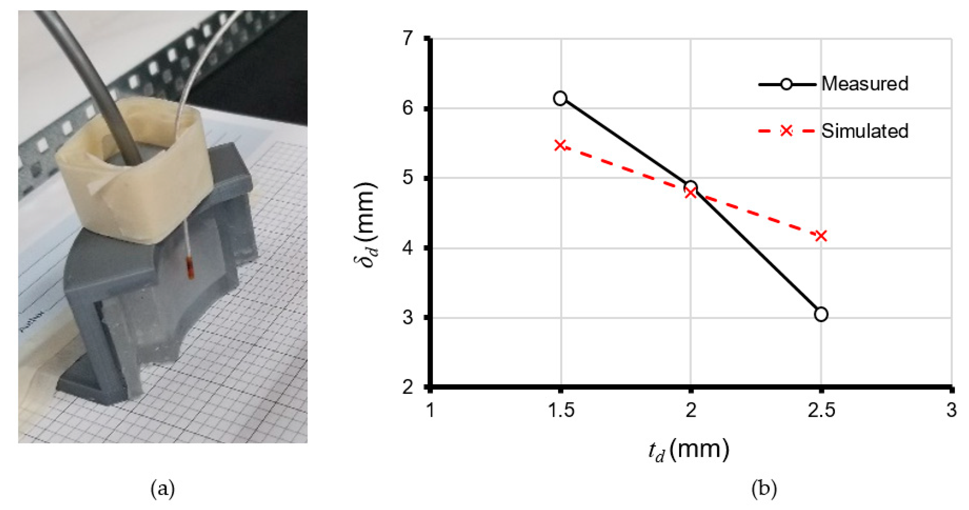
The displacement of the actuating surface was measured using a 3D Guidance TrakSTAR system [24], with an electromagnetic (EM) sensor capable of measuring 6 DOF (Figure 8a). The measurement values correspond to the distance between the sensor probe and fixed transmitter location. The displacement is, therefore, the change in distance with respect to the initial noninflated actuating surface. Figure 8b shows both the measured and COMSOL simulated displacements for the three different wall thicknesses when . Note that the measurement value is the average steady-state displacement over a 0.5 s window. The observed differences in the measured and simulated displacements are partly the result of limitations in the Mooney–Rivlin hyperelastic model, the theoretical values for the shear and bulk moduli, and the computational limitations imposed by the size of the finite element mesh used in the simulations. The smallest difference occurs at where and the largest at where . The latter case represents a ~25% error.
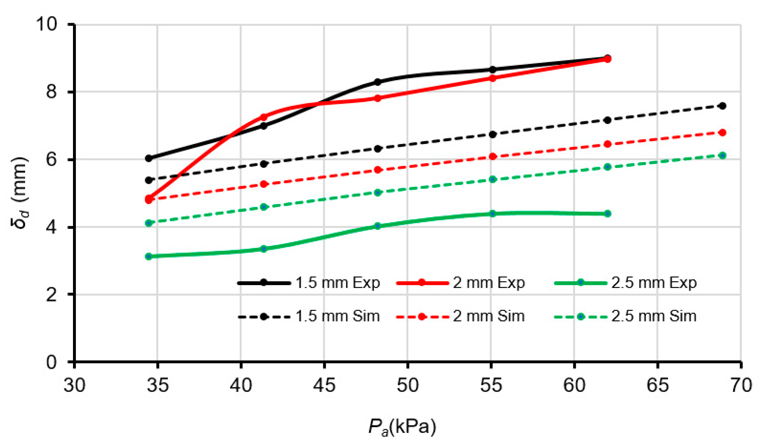
Figure 9 shows the impact of air pressure changes on the displacement of the expandable actuating wall. In these experiments was varied between 34.47 to 68.94 kPa at 6.89 kPa increments. For each , the displacement was measured by averaging three separate actuations over 10 s time trials at a sampling frequency of 120 Hz. Note that this pressure range was selected because resulted in inaccurate readings due to the limitations of the pressure regulator and gauge used in the experiments. In addition, caused a number of the fabricated actuators to prematurely rupture. The differences observed between simulated and experimental data may be due, in part, to the Mooney–Rivlin model’s inability to capture larger strains [25]. However, the simulations still illustrate the general trend of increased actuator displacement with increased air pressure.
4.2. Contact Forces and Impact of Payload
The contact force generated between the actuating surface and target object can be given by
where is the contact pressure, and is the area of contact with the target. The contact pressure for each was obtained from COMSOL simulations at . To measure the contact area when the actuator is pressurized, paint was applied to the deformable walls of the soft actuators and then the gripper assembly was used to grasp a Styrofoam sphere (dia. 60 mm). When the target was released it left an imprint of on the sphere surface that can be measured. The experiments confirm that thicker deformable walls tend to generate greater and larger (Table 2). Contact area is dependent on the geometry of the target, and organic objects like fungi are seldom identical in shape. The simplified contact force formula shown in Equation (3) allows the gripper’s behavior to be approximated.
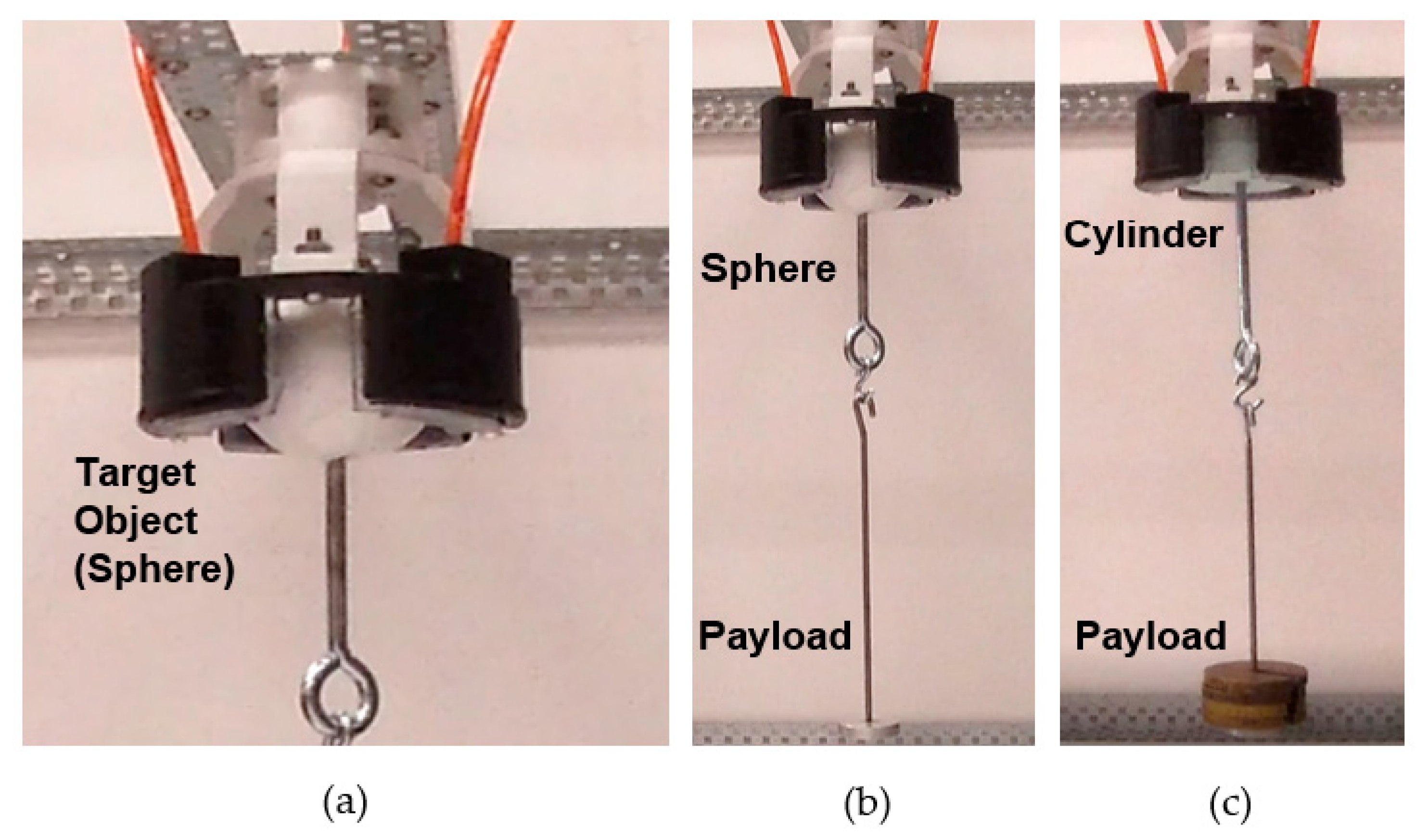
For grasping applications such as horticultural harvesting, it is also important to investigate the grip strength by measuring the payload capabilities of the pneumatic gripper with different actuator wall thicknesses. In this study, a Styrofoam sphere and cylinder with equal diameters were used as the target objects. Each target was modified by attaching a 50 g payload platform that would enable additional weights to be applied in a controlled fashion (Figure 10). This apparatus created a downward force on the grippers hold on the object and is represented as a slip test payload mass . The maximum payload of the soft pneumatic gripper (Table 2) was verified using free weights. Overall, the grippers exhibit roughly double the maximum payload capacity for cylindrical shapes over spheres. At these maximum payloads, and with similar gripper weights of about 76 g, the 1.5, 2, and 2.5 mm gripper variants have respective payload-to-weight ratios of 30, 26, and 18. These results however, appear contrary to an initial assumption that the maximum payload tests would follow the same trend as contact force experiments. The inverse relationship may be the result of changes in surface friction between the thinner inflated elastic actuator and target object. Clearly, the surface effects between the hyperelastic actuator and object need to be explored in greater detail.
4.3. Grasping Organic Objects
Automated robotic systems [18,26] are being used to harvest a wide variety of organic horticultural crops, such as delicate fruits, vegetables, and edible fungi. The proposed hyperelastic actuators and soft robotic gripper system are part of an industry driven initiative to explore the use of mechanically compliant end-effectors for gently grasping and holding mushrooms during commercial harvesting operations. Typically, these tasks are performed by traditional robotic systems that use semirigid vacuum cup grippers to twist and pull the individual mushrooms from the growing bed. Unfortunately, mushrooms are delicate fungi that can be easily bruised and damaged by excessive forces during the picking operations. In this regard, the viability of the soft gripper with PDMS actuators for horticultural harvesting applications is explored by gently grasping a variety of mushroom tops. A detailed comparative study between the proposed design and alternative approaches is beyond the scope of the current paper.
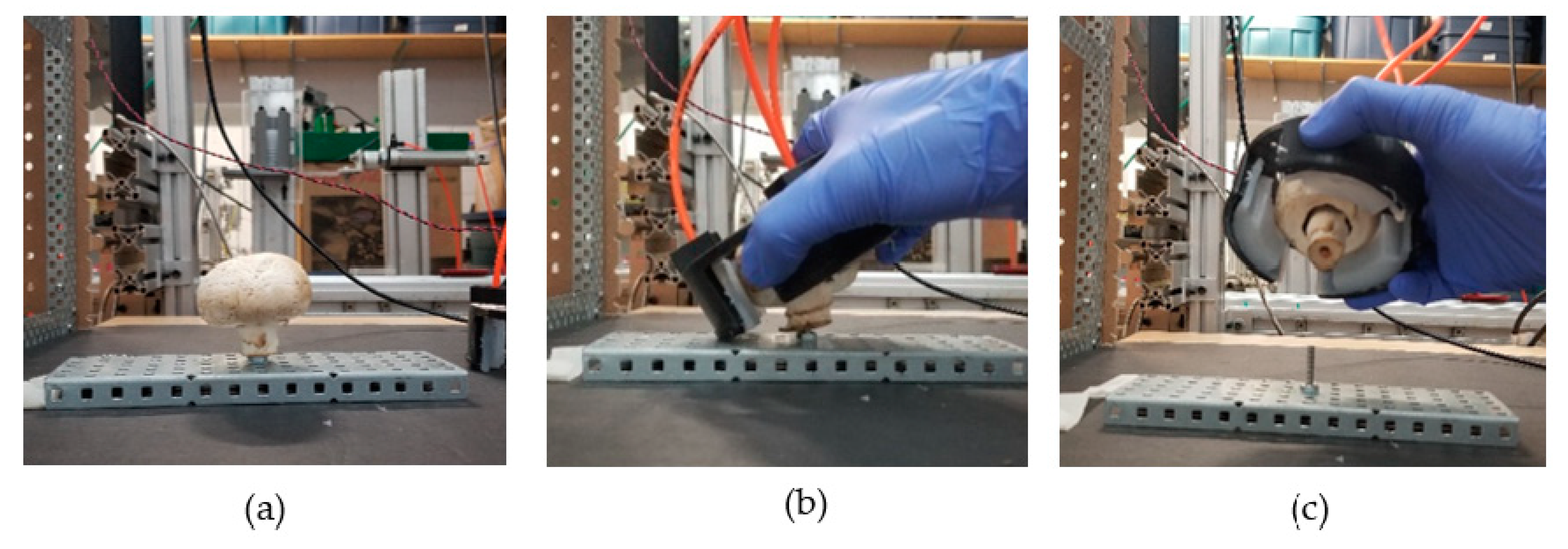
For these preliminary tests, the mushroom specimens were wedged onto a threaded bolt to simulate how they are anchored in the growing bed (Figure 11). The measures used to evaluate performance correspond to grasping success and damage inflicted. In this context, success was determined by visually inspecting the target mushroom for physical damage (or any disfigurement) after it had been grasped, pulled from the threaded rod, and held for a short period of time by the pneumatic gripper. In addition, dropping the mushroom during the procedure or being unable to make sufficient contact to lift it were considered failures.
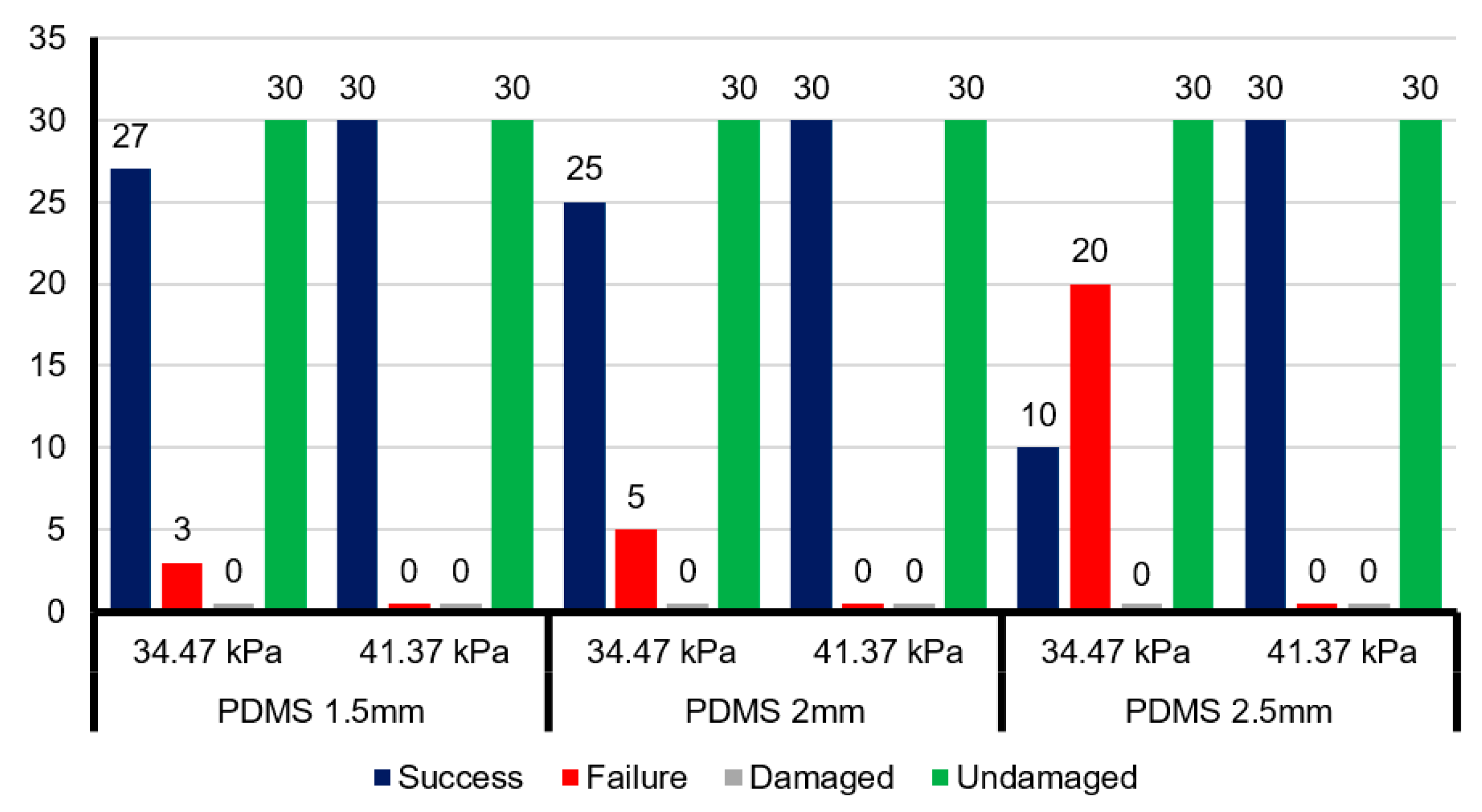
The PDMS soft actuators were assembled in three gripper assemblies with concave wall thicknesses of 1.5, 2.0, and 2.5 mm. For each gripper assembly, two sets of tests were performed with the applied air pressure equal to 34.47 kPa (5 psi) and 41.37 kPa (6 psi), respectively. A single test involved grasping, pulling, and holding 30 organic mushrooms of similar size. The experimental observations of the various soft grippers, Figure 12, indicate that PDMS actuators with performed well for both the grasp-and-hold (success/failure) and minimal infliction of surface damage (damaged/undamaged). In contrast, the gripper with soft actuators that had a wall thickness of failed 2/3rd of the grasp-and-hold tests but still did not produce any significant surface damage on the target mushroom.
Similar tests were also performed using a commercially available vacuum cup gripper for grasping these types of mushrooms. A maximum harvesting success of 37.5% was recorded, with a minimum 0% recorded grasping success for the cups tested. A maximum damage rate of 100% was observed, with a minimum of 12.5%. These cups were provided by the sponsor of the industry-driven project, Vineland Research and Innovation Centre Inc., and are proven to be poorly-suited for a mushroom harvesting application. The proposed soft pneumatic gripper at was found to have a higher grasping success rate and inflicted less surface damage on the test mushrooms. The maximum harvesting success for the PDMS grippers was recorded as 100%, and in each case the damage rate was 0%. For reference, performance indicators for various harvesting systems list a recorded harvest success rate of 75% and a damage rate of 5% [18]. Thus, the soft PDMS gripper may be a viable replacement for conventional vacuum cup grippers in terms of grasping success and damage inflicted.
4.4. Discussion
These initial experimental tests confirm that a soft robotic gripper incorporating pneumatically-driven hyperelastic PDMS actuators can successfully grasp and hold light weight delicate objects. In addition, the compact gripper geometry was not affected by gravity in the same manner as the longer soft actuator designs (e.g., PneuNet [2]), thereby making it suitable for attachment to conventional robotic manipulators with spherical wrists. Furthermore, the COMSOL simulations and experimental tests on the fabricated prototypes suggest that the current gripper design could be easily modified and adapted for a variety of applications, including harvesting horticultural produce. For example, the thickness of the actuator’s deforming wall could be adjusted for different target loads or target geometries. In addition, the actuator height can be changed for different target sizes or to change the number of active actuators in the gripper assembly (i.e., more than three). Modifying the arc of the actuator had minimal impact on the performance, but this parameter can be adjusted to accommodate more or fewer actuators in an assembly. By increasing the number discrete actuators in a larger gripper assembly, it would be possible to increase the number of contact points and grasp larger organic objects. The scalable modular design also permits multiple discrete units to be attached to the tips of discrete robotic fingers for controlled “soft touch” applications (Figure 13). Application dependent design guidelines are summarized in Table 3.
5. Conclusions
A scalable modular pneumatic actuator made from PDMS was developed for a soft robotic gripper that can grasp and hold delicate, curved organic objects, such as small fruits and edible fungi. The key design parameters were related to the size of the expandable surface area (h,α) and thickness of the deformable wall structure that makes contact with the target object. The impact of these parameters on actuator displacement were initially explored through COMSOL simulation using the simplified Mooney–Rivlin model of hyperelastic materials. These simple simulations were then used to identify appropriate dimensional parameters for the physical prototype. The actuator prototypes were fabricated using a soft lithography modeling process and inserted into a closed ring gripper assembly for experimental testing. A closed ring configuration was used for the gripper housing in order to constrain the experiments and more clearly relate actuator displacement to measured contact forces, contact areas, and maximum payload capacity prior to slippage. The initial results demonstrated that increasing the thickness of the expanding actuator wall allows the gripper to apply greater contact forces over a broader surface area. However, contrary to expectation, the slip tests showed that the thinnest wall exhibited almost double the payload capacity over the thickest . The results suggest that further studies are required to better understand the contact forces, including friction, between the hyperelastic material and target object. Finally, the viability of the soft gripper for horticultural harvesting applications was illustrated by gently grasping a variety of mushroom tops and monitoring the inflicted surface damage.
The investigative study reported in this paper also showed the limitations of the current computational modeling approach. Specifically, a more realistic hyperelastic material model and comprehensive finite element mesh need to be developed in order to improve the simulation accuracy. In addition, more complex simulations could be performed to model the contact and interaction between the soft grippers and a delicate target structure like the mushroom cap. This would require verified material properties for the various target organic objects.
Author Contributions
A.G., G.K.K. and M.K. established the project goals and conceived the hardware design. A.G. and G.K.K. developed the experiments and wrote the paper. A.G. created the mathematical models and performed both the COMSOL simulations and experimental tests. G.K.K. and M.K. contributed materials and resources for this research.
Funding
This research was funded, in part, by a Mitacs Accelerate Internship grant and Natural Sciences and Engineering Research Council of Canada (NSERC) Discovery Grant (Number: RGPIN/05858-2014.).
Acknowledgments
The authors wish to acknowledge the support of Gideon Avigad at Vineland Research and Innovation Centre, Lincoln, Ontario, Canada.
Conflicts of Interest
The authors declare no conflict of interest.
References
- Shintake, J.; Cacucciolo, V.; Floreano, D.; Shea, H. Soft Robotic Grippers. Adv. Mater. 2018, 30, 1707035. [Google Scholar] [CrossRef] [PubMed]
- Mosadegh, B.; Polygerinos, P.; Keplinger, C.; Wennstedt, S.; Shepherd, R.F.; Gupta, U.; Shim, J.; Bertoldi, K.; Walsh, C.J.; Whitesides, G.M. Pneumatic Networks for Soft Robotics that Actuate Rapidly. Adv. Funct. Mater. 2014, 24, 2163–2170. [Google Scholar] [CrossRef]
- Shepherd, R.F.; Ilievski, F.; Choi, W.; Morin, S.A.; Stokes, A.A.; Mazzeo, A.D.; Chen, X.; Wang, M.; Whitesides, G.M. Multigait soft robot. Proc. Natl. Acad. Sci. USA 2011, 108, 20400–20403. [Google Scholar] [CrossRef] [PubMed] [Green Version]
- Ilievski, F.; Mazzeo, A.D.; Shepherd, R.F.; Chen, X.; Whitesides, G.M. Soft Robotics for Chemists. Angew. Chem. Int. Ed. 2011, 50, 1890–1895. [Google Scholar] [CrossRef] [PubMed]
- Daerden, F.; Lefeber, D. Pneumatic artificial muscles: Actuators for robotics and automation. Eur. J. Mech. Environ. Eng. 2002, 47, 11–21. [Google Scholar]
- Antonelli, M.G.; Beomonte Zobel, P.; Durante, F.; Raparelli, T. Numerical modelling and experimental validation of a McKibben pneumatic muscle actuator. J. Intell. Mater. Syst. Struct. 2017, 28, 2737–2748. [Google Scholar] [CrossRef]
- Al-Fahaam, H.; Davis, S.; Nefti-Meziani, S. The design and mathematical modelling of novel extensor bending pneumatic artificial muscles (EBPAMs) for soft exoskeletons. Robot. Auton. Syst. 2018, 99, 63–74. [Google Scholar] [CrossRef]
- Miron, G.; Bédard, B.; Plante, J.-S. Sleeved Bending Actuators for Soft Grippers: A Durable Solution for High Force-to-Weight Applications. Actuators 2018, 7, 40. [Google Scholar] [CrossRef]
- Galloway, K.C.; Polygerinos, P.; Walsh, C.J.; Wood, R.J. Mechanically programmable bend radius for fiber-reinforced soft actuators. In Proceedings of the 2013 16th International Conference on Advanced Robotics (ICAR), Montevideo, Uruguay, 25–29 November 2013; pp. 1–6. [Google Scholar]
- Pedro, P.; Ananda, C.; Rafael, P.B.; Carlos, A.R.; Alexandre, B.C. Closed structure soft robotic gripper. In Proceedings of the 2018 IEEE International Conference on Soft Robotics (RoboSoft), Livorno, Italy, 24–28 April 2018; Volume 2, pp. 66–70. [Google Scholar]
- Friend, J.; Yeo, L. Fabrication of microfluidic devices using polydimethylsiloxane. Biomicrofluidics 2010, 4, 026502. [Google Scholar] [CrossRef] [PubMed] [Green Version]
- Fujii, T. PDMS-based microfluidic devices for biomedical applications. Microelectron. Eng. 2002, 61–62, 907–914. [Google Scholar] [CrossRef]
- Johnston, I.D.; McCluskey, D.K.; Tan, C.K.L.; Tracey, M.C. Mechanical characterization of bulk Sylgard 184 for microfluidics and microengineering. J. Micromech. Microeng. 2014, 24, 035017. [Google Scholar] [CrossRef]
- Kim, T.K.; Kim, J.K.; Jeong, O.C. Measurement of nonlinear mechanical properties of PDMS elastomer. Microelectron. Eng. 2011, 88, 1982–1985. [Google Scholar] [CrossRef]
- Nunes, L.C.S. Mechanical characterization of hyperelastic polydimethylsiloxane by simple shear test. Mater. Sci. Eng. A 2011, 528, 1799–1804. [Google Scholar] [CrossRef]
- Mooney, M. A Theory of Large Elastic Deformation. J. Appl. Phys. 1940, 11, 582–592. [Google Scholar] [CrossRef]
- Holzapfel, G.A. Some Forms of Strain-energy Functions. In Nonlinear Solid Mechanics: A Continuum Approach for Engineering; John WIley & Sons, LTD: Hoboken, NJ, USA, 2010; p. 238. [Google Scholar]
- Wouter Bac, C.; van Henten, E.J.; Hemming, J.; Edan, Y. Harvesting Robots for High-value Crops: State-of-the-art Review and Challenges Ahead. J. Field Robot. 2014, 31, 888–911. [Google Scholar]
- Mao, G.; Li, T.; Zou, Z.; Qu, S.; Shi, M. Prestretch effect on snap-through instability of short-length tubular elastomeric balloons under inflation. Int. J. Solids Struct. 2014, 51, 2109–2115. [Google Scholar] [CrossRef] [Green Version]
- Momentive RTV615 Technical Data Sheet 2015, HCD-10333, pp. 1–6. Available online: https://www.curbellplastics.com/Research-Solutions/Technical-Resources/Technical-Resources/RTV615-655-and-656-Data-Sheet (accessed on 5 November 2019).
- Karimi, S. Three Dimensional Numerical Simulation, Design and Structural Optimization of Pneumatically Actuated Cell Stretching Device; Tampere University of Technology: Tampere, Finland, 2015. [Google Scholar]
- Jadhav, A.N.; Bahulikar, S.R.; Sapate, N.H. Comparative Study of Variation of Mooney- Rivlin Hyperelastic Material Models under Uniaxial Tensile Loading. Int. J. Adv. Res. Innov. Ideas Educ. 2016, 2, 212–216. [Google Scholar]
- Anand, L. Moderate deformations in extension-torsion of incompressible isotropic elastic materials. J. Mech. Phys. Solids 1986, 34, 293–304. [Google Scholar] [CrossRef]
- Ascension Technology Corporation. 3D Guidance TrakSTAR User Guide; Ascension Technology Corporation: Shelburne, Vermont, 2014. [Google Scholar]
- Shahzad, M.; Kamran, A.; Siddiqui, M.Z.; Farhan, M. Mechanical Characterization and FE Modelling of a Hyperelastic Material. Mater. Res. 2015, 18, 918–924. [Google Scholar] [CrossRef] [Green Version]
- Tillett, N.D. Robotic Manipulators in Horticulture: A Review. J. Agric. Eng. Res. 1993, 55, 89–105. [Google Scholar] [CrossRef]
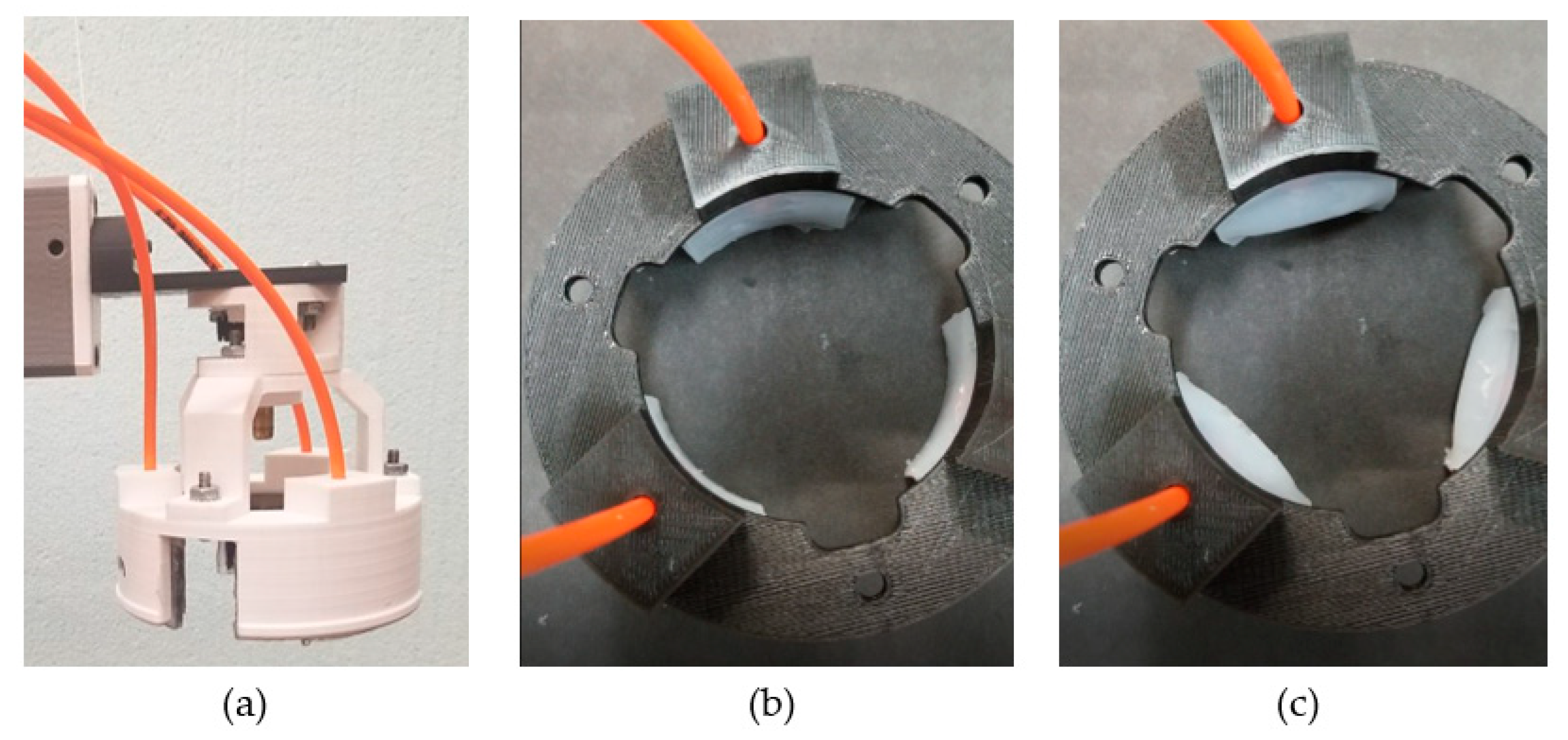
Figure 1.
(a) Robotic end-effector with the elastomeric actuators inserted into gripper assembly (colored white). Top view of gripper ring in (b) deflated state and (c) moderate inflated state.
Figure 1.
(a) Robotic end-effector with the elastomeric actuators inserted into gripper assembly (colored white). Top view of gripper ring in (b) deflated state and (c) moderate inflated state.

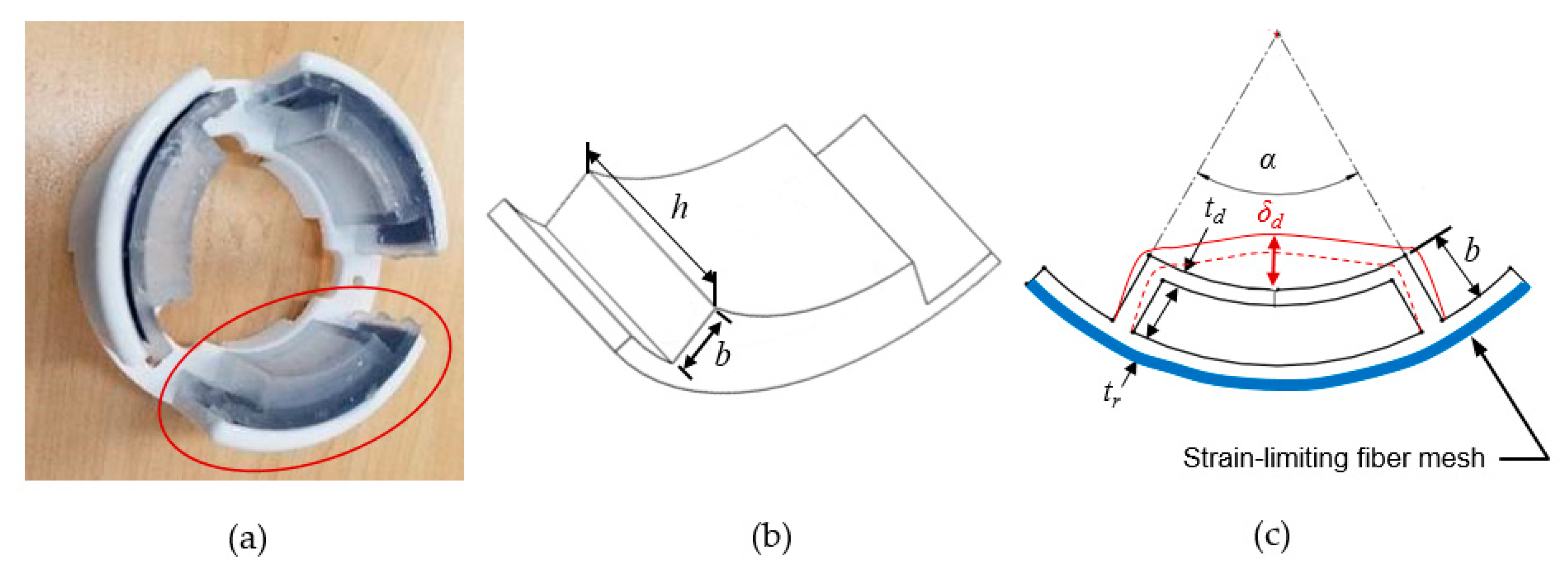
Figure 2.
(a) Bottom view of a closed ring gripper assembly comprised of three modular pneumatic actuators. (b) Outside geometry of the actuator’s pneumatic chamber. (c) Internal structure of the chamber walls, location of the strain-limiting fiber mesh (blue), and the impact of inflation on the active deformable wall (red). Note that the deformation is for visualization purposes only.

Figure 3.
(a) Wireframe of single actuator with deformable surface highlighted in blue; (b) normal vectors on the expanding surface; (c) simulated model showing expansion of the principal active wall; and (d) top view of simulated model of single actuator with expansion of the principle active wall.

Figure 4.
Displacement values at varying applied pressures for different thicknesses .

Figure 5.
Displacement as a function of both (a) actuator height (h) and (b) arc angle (α) for and .
Figure 5.
Displacement as a function of both (a) actuator height (h) and (b) arc angle (α) for and .

Figure 6.
Three-dimensional CAD models and photographs of (a) MB1: mold base 1; (b) MB2: mold base #2; and (c) single molded polydimethylsiloxane (PDMS) actuator.
Figure 6.
Three-dimensional CAD models and photographs of (a) MB1: mold base 1; (b) MB2: mold base #2; and (c) single molded polydimethylsiloxane (PDMS) actuator.

Figure 7.
The PDMS actuator fabrication process. (a) Assembly of outer walls on the base for MB1; (b) pour PDMS prepolymer in mold cavity; (c) extract PDMS part from disassembled mold; (d) fill bottom of base cavity of MB2 with partially-cured PDMS and then uncured prepolymer; (e) align and secure PDMS part on partially-cured layer; and (f) disassemble mold to remove completed actuator with a single air inlet through-hole to chamber.

Figure 8.
(a) Experimental setup for measuring actuator displacement. (b) Measured and simulated displacements for three expandable wall thicknesses .
Figure 8.
(a) Experimental setup for measuring actuator displacement. (b) Measured and simulated displacements for three expandable wall thicknesses .

Figure 9.
Comparison of experimental and simulation data for wall displacement at different input pressures .
Figure 9.
Comparison of experimental and simulation data for wall displacement at different input pressures .

Figure 10.
Experimental setup for payload tests. (a) Close-up of spherical target held in gripper; (b) sphere target for payload test; and (c) cylindrical target for payload test.
Figure 10.
Experimental setup for payload tests. (a) Close-up of spherical target held in gripper; (b) sphere target for payload test; and (c) cylindrical target for payload test.

Figure 11.
Experimental setup and manual test procedure. (a) Organic test object (i.e., mushroom) embedded on threaded rod; (b) gripper placed over mushroom; (c) gripper lifting mushroom from threaded rod.
Figure 11.
Experimental setup and manual test procedure. (a) Organic test object (i.e., mushroom) embedded on threaded rod; (b) gripper placed over mushroom; (c) gripper lifting mushroom from threaded rod.

Figure 12.
Results of grasp-and-hold experiments (success/failure) and observed damage to mushroom surfaces during the tests (damaged/undamaged).
Figure 12.
Results of grasp-and-hold experiments (success/failure) and observed damage to mushroom surfaces during the tests (damaged/undamaged).

Figure 13.
Air-driven hyperelastic actuators at the tip of discrete robotic fingers for soft touch applications developed at Western University.
Figure 13.
Air-driven hyperelastic actuators at the tip of discrete robotic fingers for soft touch applications developed at Western University.


Table 1.
Key design parameters and range of values for analysis.
| Parameter | Range of Values |
|---|---|
| Wall thickness, | 1.5 mm, 2 mm, 2.5 mm |
| Actuator chamber height, | 10–30 mm; increments of 2 mm |
| Actuator arc angle, | ; increments of |
| Applied air pressure, | 6.89–68.94 kPa (1–10 psi) |
Table 2.
Contact force and slip test results for varying wall thicknesses. Test object is a foam sphere unless stated otherwise in brackets.
Table 2.
Contact force and slip test results for varying wall thicknesses. Test object is a foam sphere unless stated otherwise in brackets.
| Slip Test Payload | ||||
|---|---|---|---|---|
| 1.5 mm | 37 kPa | 424.4 mm2 | 15.7 N | 1.175 kg 2.3 kg (cylinder) |
| 2 mm | 36.8 kPa | 498.5 mm2 | 18.4 N | 0.875 kg 1.975 kg (cylinder) |
| 2.5 mm | 35.5 kPa | 542.3 mm2 | 19.3 N | 0.675 kg 1.375 kg (cylinder) |
Table 3.
Summary of design guidelines.
| Target Condition | Performance Requirement | Design Adjustment |
|---|---|---|
| Heavier Target | Increased Maximum Payload | Decrease |
| Larger Target | Greater | Increase both ; Increase Number of Actuators |
| Flat Target Geometry | Adapt to Different Target Shape | Reduce Number of Actuators (i.e., only two) |
© 2019 by the authors. Licensee MDPI, Basel, Switzerland. This article is an open access article distributed under the terms and conditions of the Creative Commons Attribution (CC BY) license (http://creativecommons.org/licenses/by/4.0/).
Share and Cite
MDPI and ACS Style
Galley, A.; Knopf, G.K.; Kashkoush, M. Pneumatic Hyperelastic Actuators for Grasping Curved Organic Objects. Actuators 2019, 8, 76. https://doi.org/10.3390/act8040076
AMA Style
Galley A, Knopf GK, Kashkoush M. Pneumatic Hyperelastic Actuators for Grasping Curved Organic Objects. Actuators. 2019; 8(4):76. https://doi.org/10.3390/act8040076
Chicago/Turabian StyleGalley, Alexandre, George K. Knopf, and Mohamed Kashkoush. 2019. "Pneumatic Hyperelastic Actuators for Grasping Curved Organic Objects" Actuators 8, no. 4: 76. https://doi.org/10.3390/act8040076
Note that from the first issue of 2016, this journal uses article numbers instead of page numbers. See further details here.